

Super Circuits DMR8CD-3, DVQ4CD-3, DMR16CD-3 User Manual

Volume
1
DVQ4CD-3 DMR8CD-3
DMR16CD-3
User Guide

SUPER/CIRCUITS
DVQ-4CD-3, DMR8-CD3, DMR16CD3/ USER
MANUAL
© SUPER/CIRCUITS
11000 NORTH MOPAC EXPRESSWAY
SUITE 300
Austin, TX 78759
Phone 800-335-9777 • Fax 866-2567-9777
Please read instructions thoroughly before operation and retain it for future referenc e
The product specifications and information may be updated without notification.
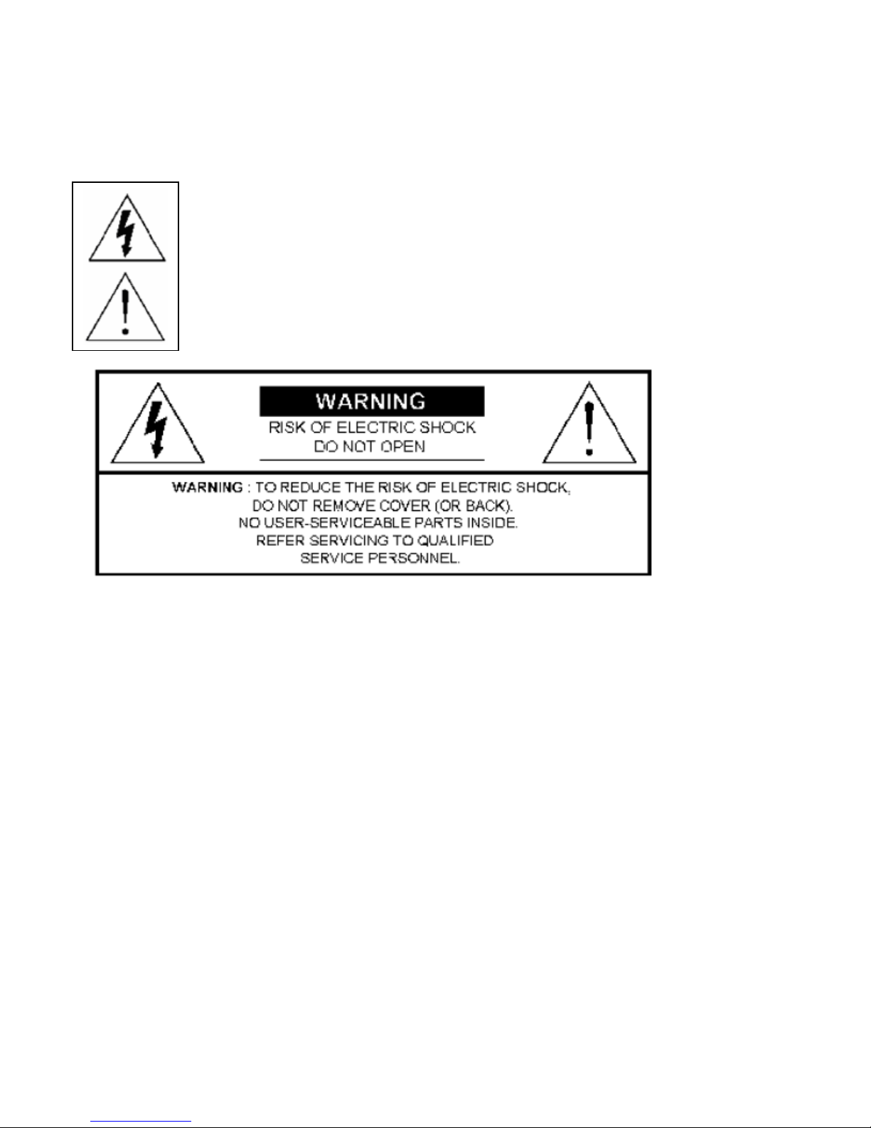
RISK OF EL ECTRIC SHOCK. WARNING: TO REDUCE THE RISK OF ELECTRIC SHOCK, DO NOT
REMOVE COVER (OR BACK). NON SERVICEABLE PARTS INSIDE PLEASE REFER SERVICING TO
QUALIFIED SERVICE PERSONNEL
All the safety and operating instructions should be read before operation. Improper
operation may cause permanent damage.
The lightning flash with arrowhead symbol, within an equilateral triangle, is intended to alert the user to
the presence of uninsulated "dangerous voltage" within the product's enclosure that ma y be of sufficient
magnitude to constitute a risk of electric shock to persons.
The exclamation point within an equilateral triangle is intended to alert the user to the presence of
important operating and maintenance-(servicing) instructions in the literature accompanying the
appliance.
• Use provided adapter.
• Handle equipment with care.
• Do not expose this equipment to open sunlight.
• Do not spill liquid on equipment. Do not use this equipment near water.
• Please power down the unit before unplugging.
• Do not Power on & off quickly (Give unit 15 to 30 seconds when powering off & on).
• Service and Installation should be made by a qualified service technician.
• For your safety, unplug the power before moving, installing, or replacing components.
• Make sure all the power cable and wires are properly installed before operating.
• Avoid dramatic temperature changes, dust, and humidity.
• Operating temperature ranges are from 5C~40C. (41 to 104 degree Fahrenheit.)
• Keep this unit in a well-ventilated place and away from any heat-generating objects.
• Do not block the fan and vent areas.

Table of Contents
Date: 2007/12/02 VER: 1
PRODUCT OVERVIEW………………………………………………………….…...6
Features…………………………………………………………………………………………….……. 6
Package Includes…………………………………………………………………………………….…..6
Front & Rear Panel Description
• Front Panel Introduction……………………………………………………………………..…8
• Rear panel Introduction………………………………………………………………….…....11
Getting Started………………………………………………………………….…...14
Installation Guide……………………………………………………………………………….……….14
• DVR and Camera Installation……………………………………………………….…….…16
• DVR and Monitor Installation……………………………………………………….………..17
Basic Menu Setup………………………………………………………………...…18
Getting Started with Basic Menu Setup………………………………………………………….…...18
• System Menu……………………………………………………………………………….…20
• Factory Default………………………………………………………………………….…….20
• Clear HDD……………………………………………………………………………….…….21
• Time/ Date Setup………………………………………………………………………… .….23
• Record In Motion………………………………………………………………………….…..24
Advance Menu Setup……………………………………………………………....31
System Menu…………………………………………………………………………………………....31
• Display Setup……………………………………………………………………………….….32
• Monitor Setup………………………………………………………………………………..…34
• Configuration…………………………………………………………………………………...35
• HDD Management……………………………………………………………………………..36
o Time/ Date Setup………………………………………………………………….…37
o Camera Setup…………………………………………………………………….….38
• Motion Setup…………………………………………………………….….40
• Interval Setup……………………………………………………………....46
o Alarm Setup……………………………………………………………………….….47
o Event Popup Setup……………………………………………………………….…47
o Buzzer Setup………………………………………………………………………...48
o Password Setup……………………………………………………………..…...….48
o System Information……………………………………………………………….…49
• Record Setup……………………………………………………………………………....….50
o Record Configuration………………………………………………………………..50
• Overwrite………………………………………………………….……..….50
• Multiplex…………………………………………………………….………50
• Quality……………………………………………………………………….51
• Resolution………………………………………………………………..…51
…………..………………………………………………………...….8
4

• Record in Alarm………………………………………………………….....51
• Record in Motion……………………………………………………..….….51
• Continuous Record……………………………………………………...….51
• Schedule Setup……………………………………………………………………………..…52
• Holiday Setup……………………………………………………….…………..…….….……54
• CD Backup………………………………………………………………………….…….....…54
o CD/ DVD Backup………………………………………………………………….…55
o CD/ DVD Backup Player Software Installation…………………………………...56
• External Devices……………………………………………………………………….….…..60
o TCP/IP Setup…………………………………………………………………..…….60
o RS232C Setup……………………………………………………………………….62
o PANTILT Setup………………………………………………………………………63
o SPOT Setup……………………………………………………………………..…..64
o AUDIO…………………………………………………………………………….….65
• Factory Default……………………………………………………………………………..…66
• LANGUAGE ……………………………………………………………………………….…..67
Advance Hardware Installations
SPOT………………………………………………………………………………………………....68
LOOP……………………………………………………………………………………………..….69
Sensor and Alarm Installation…………………………………………………………………..…70
Serial Port Setup……………………………………………………………………………….…...71
PTZ Camera Installation and Operations……………………………………………………...…73
Microphone and Speaker Installation………………………………………………………….…75
HDD Installation……………………………………………………………………………….……76
………………………………………………………..…...68
Operation…………………………………………………………………………..…77
Display Configuration……………………………………………………………..………….……77
Screen Switch……………………………………………………………………………….….….79
PIP View……………………………………………………………………………………….……79
Freeze View………………………………………………………………………… ………….…..79
View in Sequence………………………………………………………………………………….80
Zoom View………………………………………………………………………………………….80
Key Lock………………………………………………………………………………………….…81
Switch Audio Channel……………………………………………………………… ………….….81
Record………………………………………………………………………………………………82
Playback………………………………………………………………………………………….…83
Search Mode……………………………………………………………………………………….84
Network and Client Software………………………………………………….….88
Network Introduction………………………………………………………………………………88
• Network Installation and Setup…………………………………………………………88
Installing Network Software……………………………………………………………………….94
Dynamic IP Settings…………………………………………………………………………...…101
Remote Live View VIA IE Browser…………………………………………………………..…107
Web Network Backup…………………………………………………………………………....109
Specifications………………………………………………………………………114
Appendix 1 Record Time Table……………………………………….……..….116
Appendix 2 System Configuration………………………………………..……118
Appendix 3 Play Only Mode………………………………………………..……118
5

Chapter
1
Product Overview
1. Features
DVQ 4 records 120 frames per second max using lowest resolution.
DMR8/16 records 480 frames per second max using lowest resolution.
Remote viewable via 10/100 Ethernet
Easily backup hard drive data to DVR-R burner
Selectable motion detection recording
Instant search by time, alarm events, etc.
2 internal hard drive bays
Password protection
Jog/Shuttle dial allows frame by frame review
On-screen setup menu, title, and system timer.
Time/Date stamp
Time lapse and real-time recording.
2. Package Includes
• DVQ or DMR unit × 1
• Power Supply × 1
• Power Cable × 1
• Remote Controller × 1
• Manual × 1
• Software CD-R × 1
• Accessories × 1
• Battery × 2
6

Ca t
DVR-1 CD Manual
REMOTE Power cord Power Supply
Package
NOTE: Check the package to make sure that you receive all accessories which include the
components shown above.
7
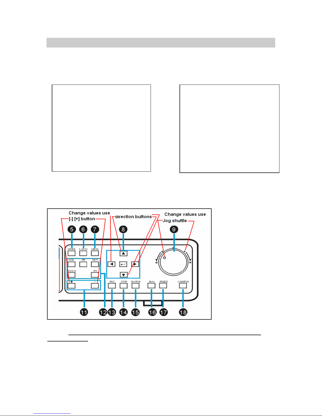
Front & Rear Panel Description
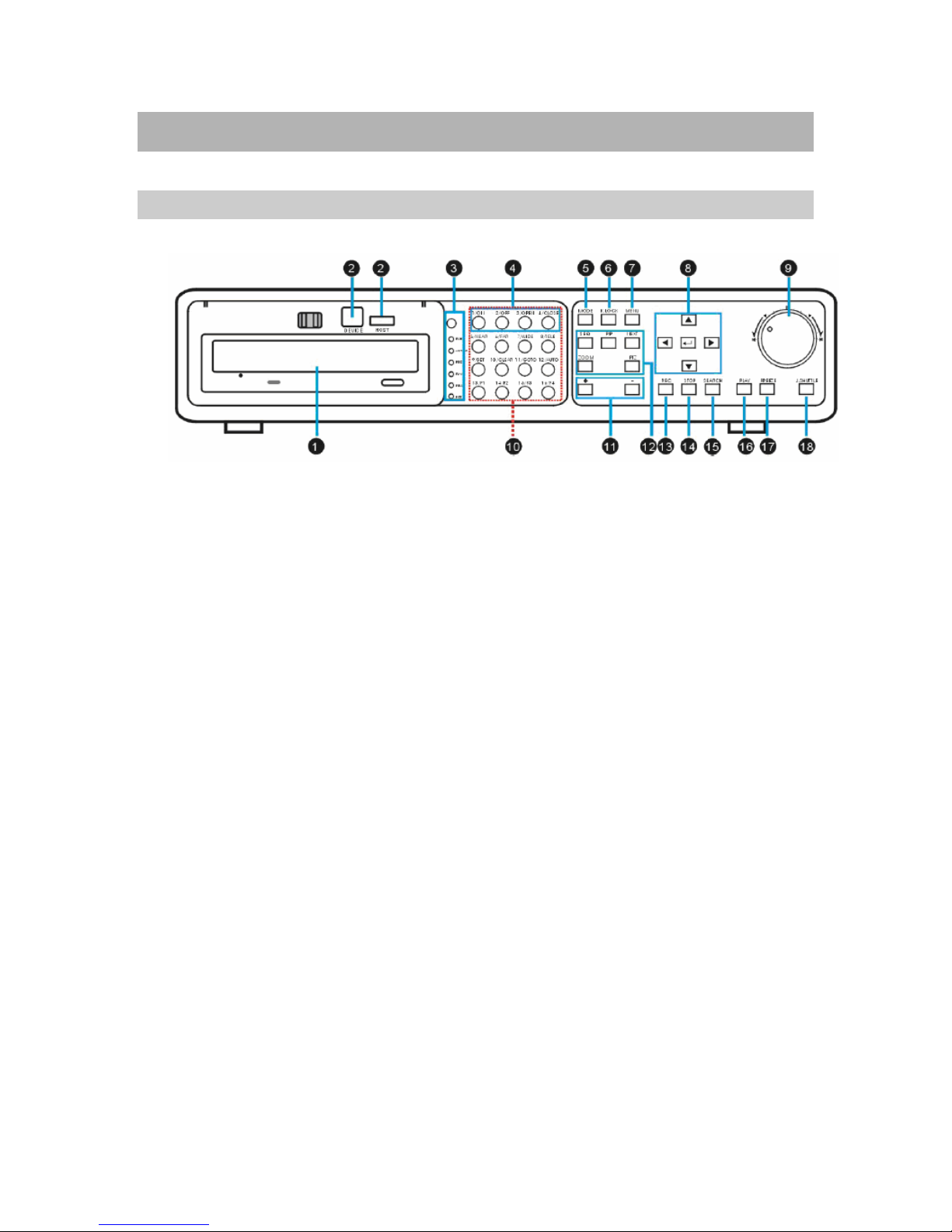
Front Panel Introduction
**Special NOTE for line items 6 and 19**
1. DVD+R burner
• Built-in DVD+R burner.
2. USB Port
• Used to connect PC to DVR for firmware upgrade.
• USB memory stick backup.
3. IR Receiver & LED Lamps
• IR Remote Controller Receiver.
• DVR Status LED.
o RUN- Flashes when picture by picture play through J. Shuttle.
o ACTIVE- On when the J. Shuttle is ready for use.
o REC- On while recording and flashes at stand-by mode.
o PLAY- On while playback.
o FULL- On when HDD storage is full.
o NET- On when the DVR is connected remotely.
4. 1~16 Channel Button
• Select channel for full screen display.
5. MODE
• Switch to full or split screen display.
6. **K.LOCK**
• Security lock out to help prevent unwanted DVR access. DO NOT PUSH THIS BUTTON
unless you know what your password is. Default password is blank (_______), press the
“ENTER key” to confirm password. See your “PASSWORD SETUP” to change your
password.
7. MENU
• Enter the menu set up.
8

8. Arrow Keys & ENTER
• Directions- Navigate the menu.
• ENTER- Confirm the selected options.
9. Jog Shuttle
• Use inner Jog shuttle control for frame by frame image display. Turn clockwise for
forward and turn counter-clockwise for reverse.
• Use outer Jog shuttle control for fast forward and fast reverse.
P.1 Appear
10. PTZ
• Press the PTZ buttons to control the PTZ camera directly.
11. [ + / - ]
• Adjust set-up value.
• Control screen display channel.
12. Control
• SEQ/AUDIO - Press for AUDIO. Press and hold for 3 seconds to enter SEQ mode.
• SEQ -Full screen sequencing/ PIP screen sequencing.
• AUDIO - Press to play the audio, and press again to switch audio channels.
• PIP – Press PIP to enter the Picture in Picture mode.
• NEXT –
o Go to the next PTZ command in PTZ mode.
o Switch from full screen display to split screen display.
• ZOOM - Press ZOOM key to enlarge specific picture area.
13. REC
• Press to activate continuous record. Record settings used for recording are Super fine
quality and Best resolution.
14. STOP
• Stop record.
• Stop playback and return to the live mode.
15. SEARCH
• Enter search options. (Percentage, date / time, or the event list).
16. PLAY
• Play recorded video.
17. FREEZE
• Freeze in full screen or split screen
18. J.SHUTTLE Button
• Activate the Jog Shuttle and press again to deactivate
19. **ENTER KEY**. Enter your selections for MENU entries.
9

10
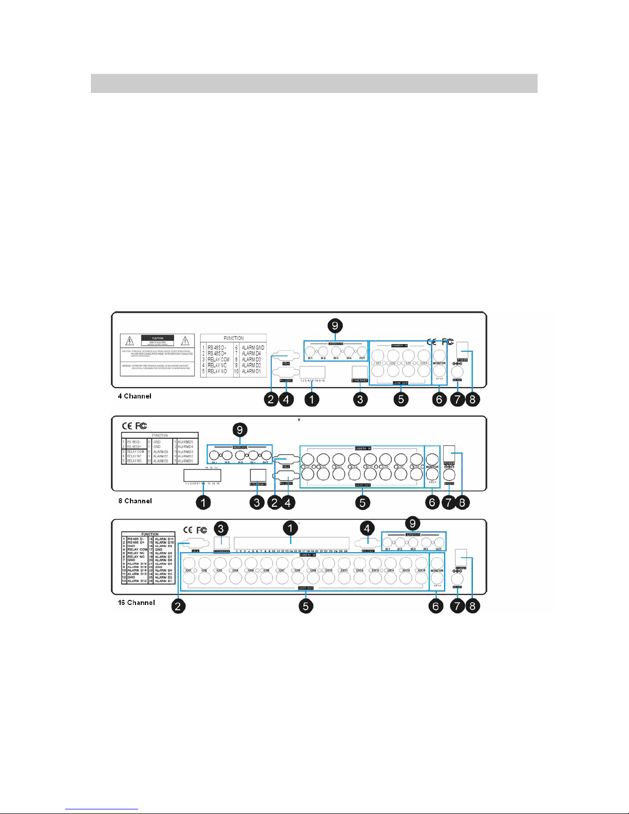
BACK PANEL INTRODUCTION
1. RS485, Relay Output, Sensor Input
• RS485, for connection to PTZ cameras.
• 16 sensor inputs and 1 relay output.
2. VGA Output
• Connection to a VGA monitor or TFT LCD.
11

3. ETHERNET
• LAN connection.
4. RS-232C
• Use to connect to PC or other serial control devices.
5. 1~16 Camera Input/ LOOP Output
• CAMERA IN- channels 1~16 camera input.
• LOOP- channels 1~16 camera video out.
6. Monitor / SPOT Output
• MONITOR - Connection to main monitor.
• SPOT- Alarm or motion triggered monitor output display.
7. Power Input
• DC power input (DC12V)
8. Power Switch
• Power ON/OFF
9. Audio Input/Output
• 1 ~ 4 Audio input channels/ 1 Audio output channel.
IR remote controller introduction
1. MENU
• Enter menu or exit
2. Split /OSD
• 4S: 4 split screen
• 9S: 9 split screen
• 16S: 16 split screen
• AUDIO: Press to play the audio, press again to
go to the next audio channel.
3. 1~16 Channel
• Switch channel in live or playback.
4. Control function
• FRZ - Freeze screen display
• SEQ - Display screen sequence
• ZOOM - Press ZOOM key to enlarge specific
picture area. Use the direction buttons to guide
ZOOM target.
• PIP- Picture in Picture. Enter PIP mode in full
screen
5. Mode/PT
• MODE- Multi-screen display
• P/T- Enter the PTZ camera control mode
12

6. SEARCH/-/+/NEXT
• SEARCH - Open the search window in playback
• [-]/[+] – Adjust options in set-up
• NEXT- Go to the next PTZ command in PTZ mode. / Go to the next channel in full screen
display/ Go to next page in split screen display.
7. Rec
• Continuous Record.
8. Stop
• Stop the record and return to previous record setting.
• Stop playback and return to the LIVE mode.
9. Functions
• PLAY - Play recorded video.
• PAUSE - Pause playback.
• REW - Fast rewind, press again to adjust speed.
• FF - Fast forward, press again to adjust speed.
• STEP - Play frame by frame.
• SLOW - Slow motion playback, press again to adjust speed.
10. ENTER
• Select option.
11. Direction
• Navigate the menu.
13

Chapter
2
GETTING ST ARTED
Installation Guide
Camera and Monitor Installation
This manual has been carefully written to help you assemble and configure your digital video
recorder system for optimal performance. It’s easy to setup your digital video recorder just follow
the instructions on pages 14 through 30 for your basic setup. If you have any comments
questions about this manual, please feel free to call us at 800-335-9777.
1. Remove your monitor from the box for testing your cameras and cables. You can use a TV
set with a video input if you don’t have a monitor. Plug your monitor into a 110-120 AC power
source. Do not mistake the antenna input on the TV for a VIDEO INPUT. Monitors and TV’s
have video inputs clearly marked. The TV RCA input will look some what like the image
below (labeled VIDEO INPUT). This type of input connector is called an RCA female input
jack.
2. Remove your cameras and camera power supplies from the box. Make sure you’re using
power supplies that have a REGULATED POWER SUPPLY 12 VOLT OUTPUT (very
important). Most power supplies have a label on the back that will tell you the type of output
the power supply is capable of producing. If there is no label, DO NOT USE THE POWER
SUPPLY.
14

NOTE: Un-regulated power supplies are very common and will damage your cameras.
3. Connect each one of your cameras to your regulated power supply and cable assembly.
Most cable assemblies are 100 ft long or more. You will see all types of cable configurations
here is one example of a cable option below.
4. Test each component of your video system prior to installation. Connect each camera
directly to the video monitor, using a new power adapter and cable for each camera. This will
test each component of your video system and confirm proper function prior to installation.
15
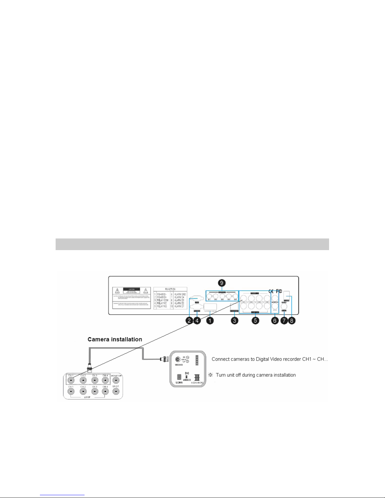
5. Connect the digital video recorder to cameras.
DVR and Camera Installation
16
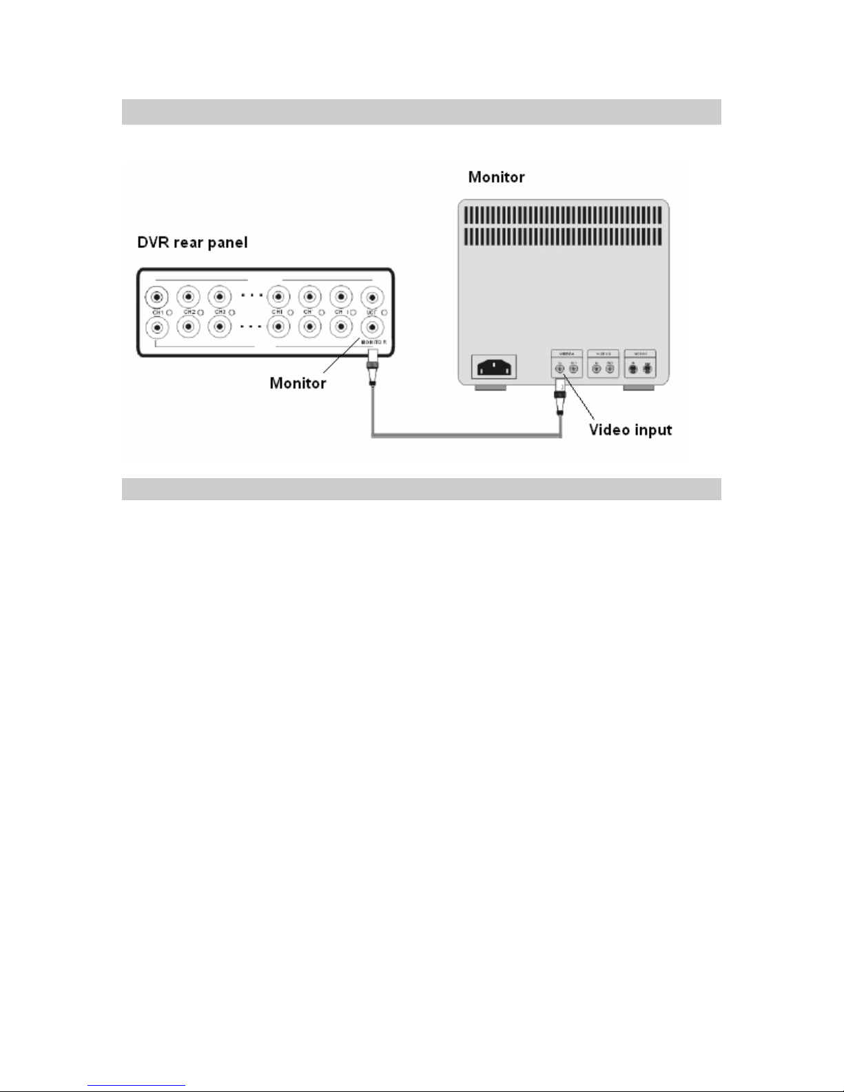
DVR and Monitor Installation
DVR system diagram
17

Chapter
3
BASIC MENU SETUP
GETTING STARTED with the BASIC MENU
SETUP
In this section we will cover basic menu settings to get you started and operational right away.
Connect the AC Power Cord with Power Adapter and plug into an electrical AC outlet. Power
switch is on the rear panel, turn the switch on. It will take approximately 5 to 15 seconds for the
system to completely finish initializing.
Caution: Only use 100~240VAC 50~60HZ / 12VDC 8A or 5A power supply.
18

Before operating the digital video recorder you will need to set up the SYSTEM MENU within the
DVR.
Go into the MENU and run the FACTORY DEFAULT, CLEAR HARD DRIVE and change the
SYSTEM TIME.
1. FACTORY DEFAULT
2. CLEAR HARD DRIVE
3. SYSTEM TIME
BASIC MENU SETUP
1. Press the MENU key on the front panel to login.
2. Use CH. SELECTORS 1 ~ 16 to key in the password.
3. Press ENTER to confirm and you will enter the
Menu system.
NOTE: You don’t have a password in the
system, if this is your first install. Your
password is blank or “(___________) “, do not
enter a password at this time, and hit the >
ENTER key.
19
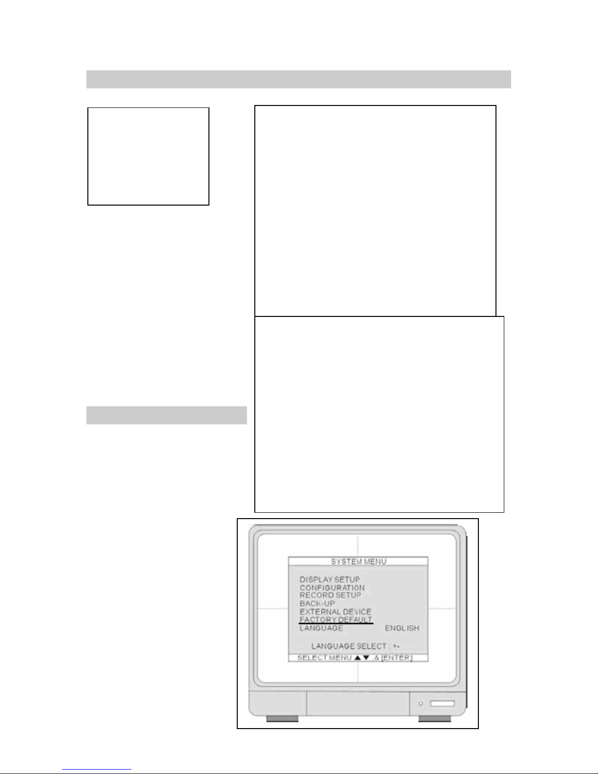
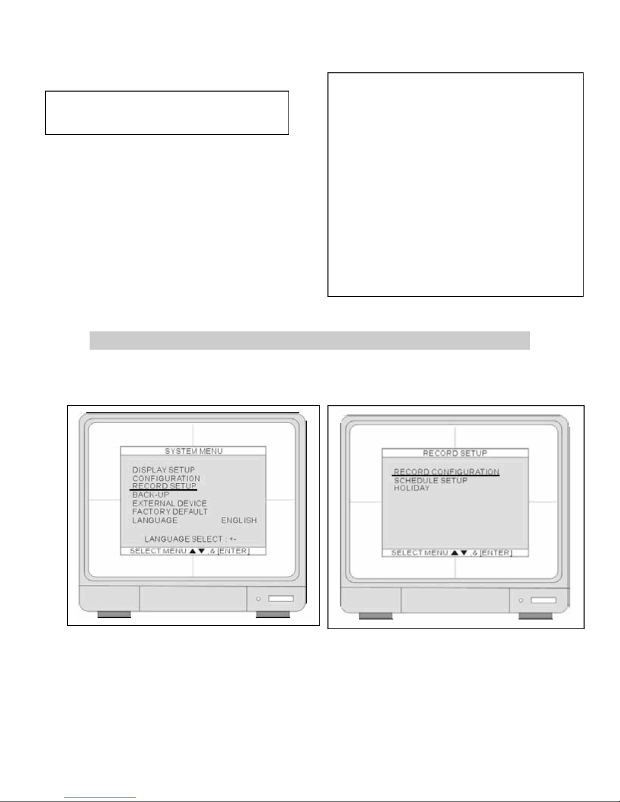
SYSTEM MENU
1. DISPLAY SETUP
2. CONFIGURATION
3. RECORD SETUP
4. BACK-UP
5. EXTERNAL DEVICE
6. FACTORY DEFAULT
7. LANGUAGE
.4 Set
CH
AP
Up
FACTORY DEFAULT
4. Press UP and DOWN
arrow keys and hit the
ENTER key for selection.
Move the cursor to
FACTORY DEFAULT and
hit the ENTER key.
20
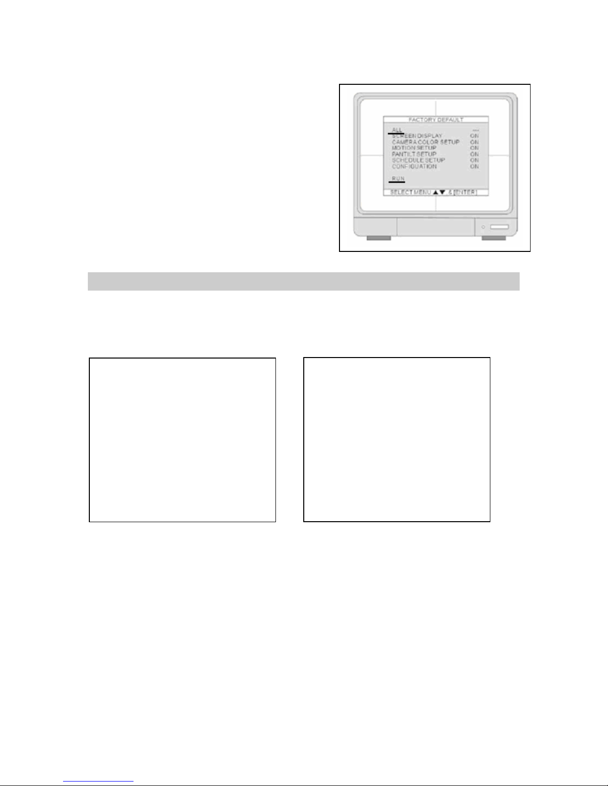
5. Move the cursor to ALL and hit the ENTER key to
turn all FACTORY Defaults ON. Move the cursor
to RUN and press the ENTER key to execute the
Factory Default. All options will turn to OFF.
6. Hit MENU Key to exit.
7. Let’s CLEAR the HDD.
CLEAR HDD
In the SYSTEM MENU select CONFIGURATION and hit the ENTER key. Go to HDD
MANAGEMENT and hit the ENTER key.
21
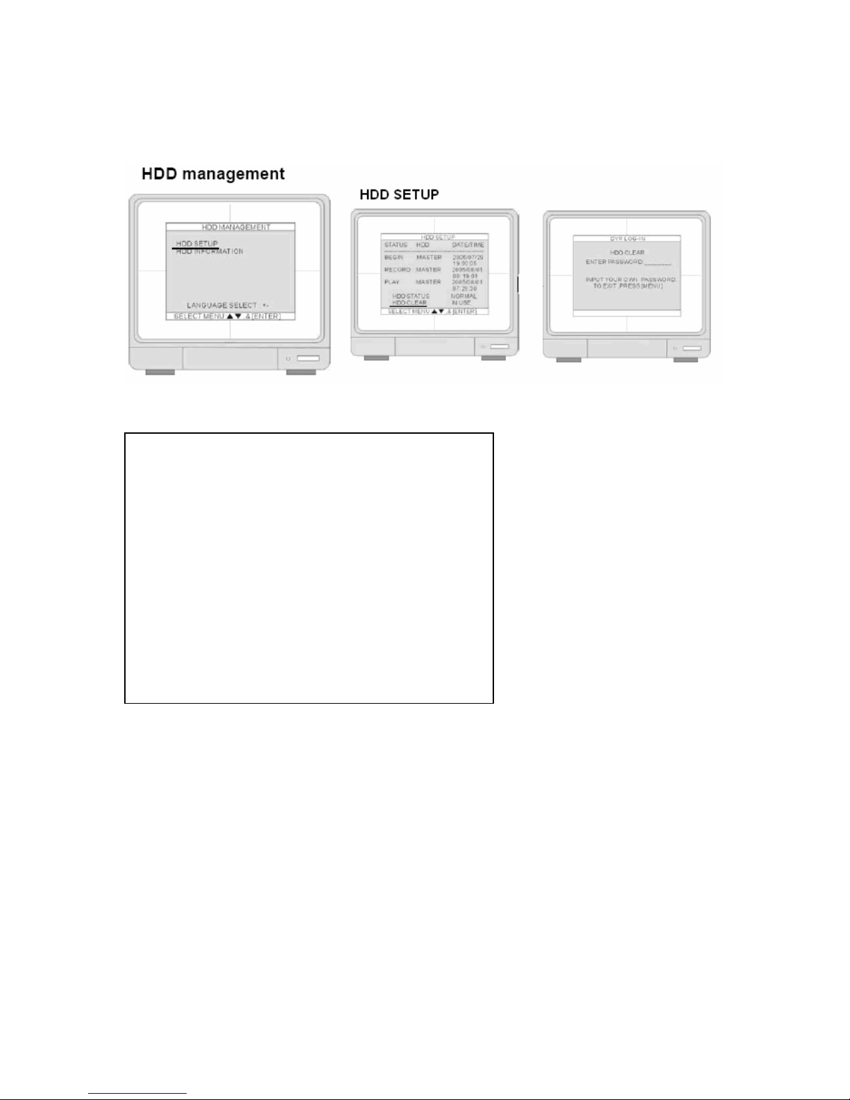
8. Select HDD SETUP hit the ENTER key, move the cursor to HDD CLEAR and hit the ENTER
key. Enter a password, which at this time is blank (_________), just hit the ENTER key
again. HHD CLEAR will show EMPTY.
9. Hit the MENU Key twice to exit to CONFIGURATION MENU.
10. Go to TIME/ DATE SETUP.
22
TIME/ DATE SETUP
11. From the main SYSTEM MENU select CONFIGURATION, go to TIME/DATE SETUP hit
the ENTER key.
12. The date and time set by the manufacturer maybe different from your time zone. It is very
important to set up the system date and time before the DVR starts recording. Set the date
and time by using direction buttons and [-] [+] button or Jog shuttle.
NOTE:
playback errors.
DO NOT change the date and time after the recording starts it may and cause
23
• Date format- Asia/American/European
Time format- 12 hours/24 hours
Month format- English/Numeric
13. Use American, 12 hours/24 hours is
optional, use English.
14. Move on to MOTION SETUP. Exit
TIME/DATE SETUP and go to SYSTEM
MENU.
RECORD IN MOTION
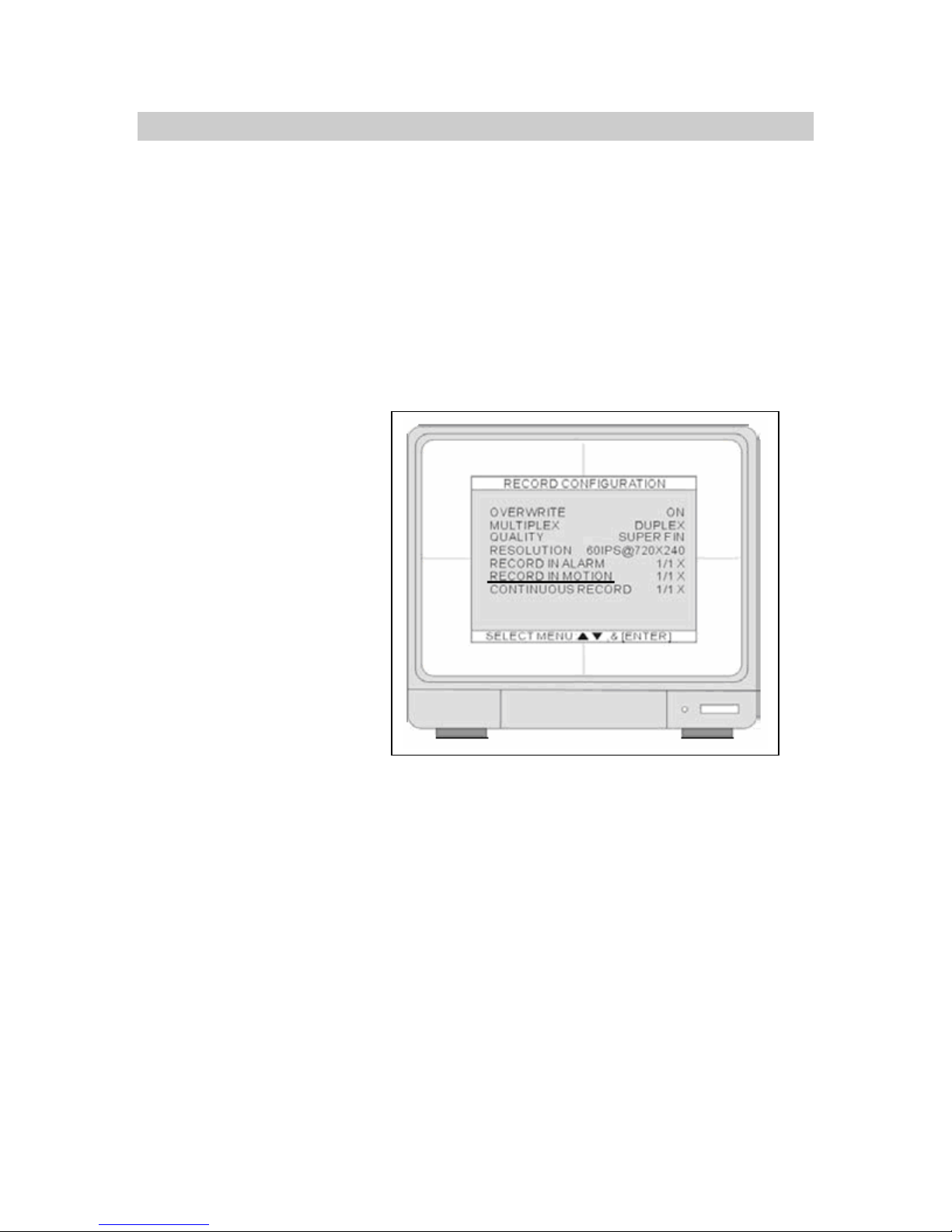
15. Under SYSTEM MENU select REORD SETUP and hit the ENTER key. Select RECORD
CONFIGURATION.
24
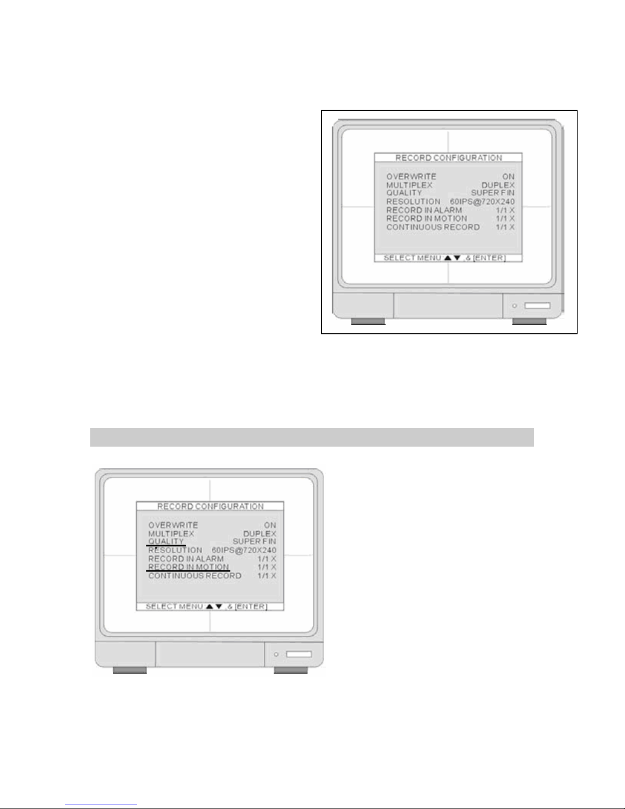
Use the UP and DOWN arrow keys to select an item. Use the [+] and [-] keys to change the
value.
16. Set OVERWRITE to ON. When the hard
drive is full, the system will overwrite the
earliest recorded data. If the DVR has two
hard drives, the overwriting starts from
the Master drive. For this exercise,
leave OVERWRITE in the ON position.
17. Set MUTIPLEX to DUPLEX, this will allow
record and remote connection
simultaneously. The DVR stops recording
while the DVR enters playback. Leave in
DUPLEX mode.
18. Move on to QUALITY and RECORD IN MOTION.
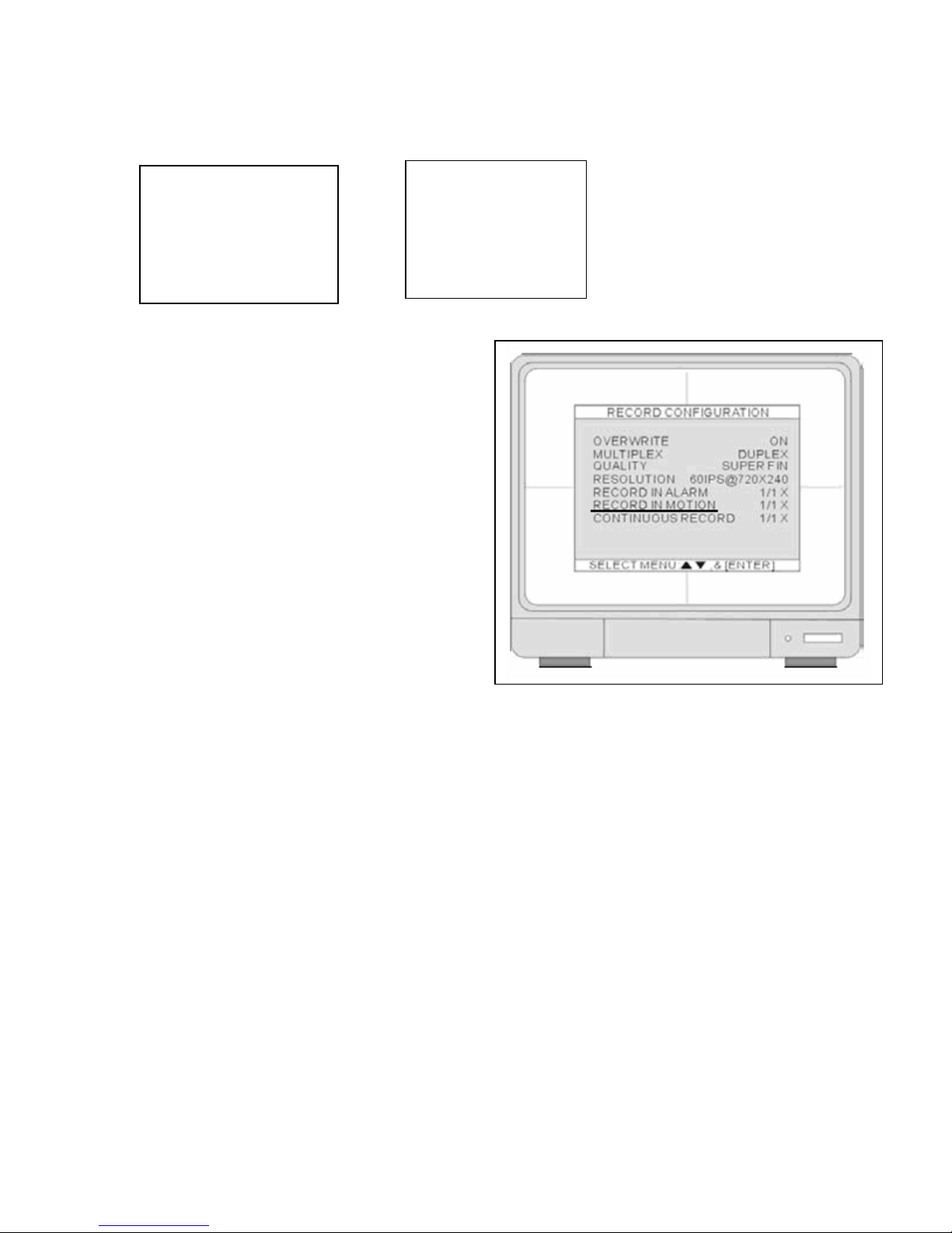
QUALITY & RECORD IN MOTION
Review the charts below they will help you decide what options to go with for QUALITY and
RECORD IN MOTION settings.
25
The QUALITY mode has 5 options. Option names can be different depending on DVR version.
4, 8, 16 CHANNEL DMR.
1. HYPER
2. SUPER
3. HIGH
4. MID
5. LOW
The RECORD IN MOTION mode has different
parameters to choose from 1/1, 1/2, 1/3, 1/4… to
1/999. The higher the denominator the longer
period you can record. The recording speed is
expressed in fractions. The 1/ 1 record setting
will record at full recording speed. The 1 / 2
record setting will record at half of the recording
speed. The 1 /3 record setting will record at one
third of the recording speed.
QUALITY features provide different levels of
quality depending on your application.
Sometimes we are willing to give up on video
quality to get more hours out of our digital video
recorder. IPS is IMAGES PER SECOND or the
number of pictures your digital video recorder will
take in 1 second. A good example of IPS is to
imagine taking 30 pictures with a digital camera
of some one walking across a room. If you laid
out the 30 pictures, what you will have is a
smooth flowing sequence of pictures of someone crossing a room. If you take out every other
picture, you have 12 pictures and you would have a snap shot picture affect. A 12 picture
sequence or 12 images a second is not considered real time video. 30 to 15 image s per second
is considered real time and 12 to 1 images a second will reduce the real time affect.
Here is an example to further explain the charts below; for this exercise Lets say we are using a 4
channel DVR and want to record for 7 days. If we look at the chart we have four choices;
1. 8.4 days
2. 7.5 days
3. 7.2 days
4. 9 days
5. 10.8 days
8, 16 CHANNEL DMR.
1. SUPER FINE
2. FINE
3. ENHANCED
4. NORMAL
5. BASIC
26

If you like high quality video, then your choice would be 7.2 with a QUALITY at HYPER and an
IPS set at 1/4. If you would like a better flowing video (closer to real time) then your choice would
be 8.4 with QUALITY at LOW and an IPS set at 1/2.
4 Ch
IPS 1/3
This testing was done with a 250G HDD and data is expressed in days. This data is a rough
estimate to get you close to your time target. Do a test run of your QUALITY and RECORD IN
MOTION settings and review your results.
¾ NOTE:“TEST YOUR SETTINGS BEFORE FINAL INSTALL”
4 Ch
IPS 1/3
8 Ch
IPS 1/3
16 Ch
IPS 1/3
IPS Low Mid High Super Hyper
Low Mid High Super Hyper
Low Mid High Super Hyper
Low Mid High Super Hyper
1/1
1/2
1/4
1/5
1/6
1/1
1/2
1/4
1/5
1/6
1/1
1/2
1/4
1/5
1/6
1/1
1/2
1/4
1/5
1/6
8.4
12.6 9.4
16.8 12.6 10.1 8.4
25.2 18.9 15.1 12.6
12.6 9.4 7.5 6.3 5.4
16.8 12.6 10.1 8.4 7.2
25.2 18.9 15.1 12.6 10.8
10.5 7.9 6.3 5.2 4.5
12.6 9.4 7.5 6.3 5.4
QUALITY
4.2 3.1 2.5 2.1 1.8
6.3 5 4.2 3.6
7.5
21 15.8 12.6 10.5
QUALITY
4.2 3.1 2.5 2.1 1.8
8.4 6.3 5 4.2 3.6
21 15.8 12.6 10.5 9
QUALITY
2.1 1.5 1.2 1 0.9
4.2 3.1 2.5 2.1 1.8
6.3 4.7 3.7 3.1 2.7
8.4 6.3 5 4.2 3.6
QUALITY
1 0.75 0.6 0.5 0.45
2.1 1.55 1.25 1 0.9
3.1 2.3 1.87 1.5 1.3
4.2 3.1 2.5 2.1 1.8
5.2 3.9 3.1 2.6 2.2
6.3 4.7 3.7 3.1 2.7
6.3 5.4
7.2
9
10.8
27
EXTENDING YOUR RECORDING TIME
We can extend the recording time by introducing a larger hard drive or increasing the RECORD
IN MOTION parameters - 1/1, 1/2, 1/3, 1/4… to 1/999. The higher the denominator the longer
period you can record.
NOTE: You are not limited to the tables above; remember increasing the lower number or
denominator will get you 1 day to months of recording time. To start find the nearest date you
would like, for example lets take the 16 channel DVR and I’m looking for 30 days. You would
start by looking at LOW QUALITY and an IPS of 1/6. Take the 6.3 days, divide 30 days by 6.3
and this will give us 4.76. Multiply 4.76 by the denominator 6 and this will give us 28.57, take it to
the nearest whole number. Enter an IPS of 1/29 and LOW QUALITY to get you in the ball park of
30 days. Remember to do a test run.
18. Select how many days you would like and enter the values.
19. Exit by hitting MENU once
and go into SCHEDULE
SETUP.
28
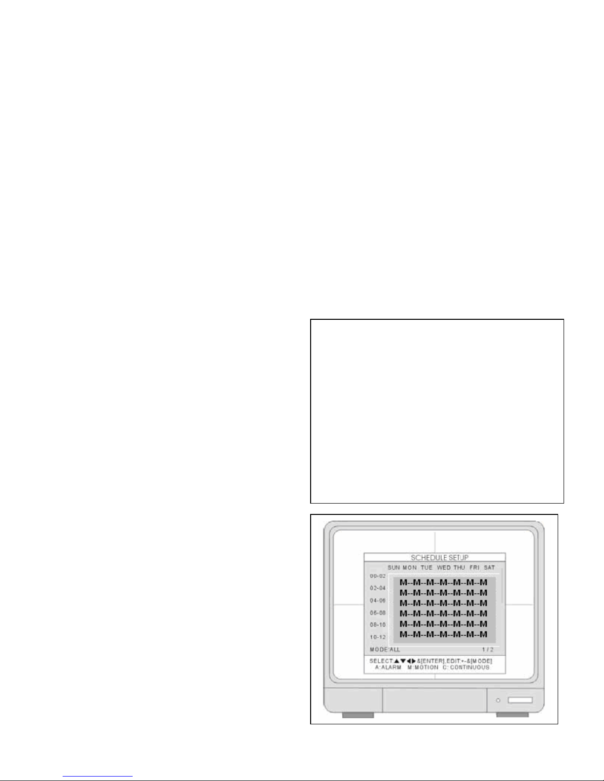
SCHEDULE SETUP
20. Hit the ENTER key.
21. Hit the “–“ minus key.
Your monitor screen should look like this,
showing all M’s indicating motion detection.
22. If not press the MODE key.
29
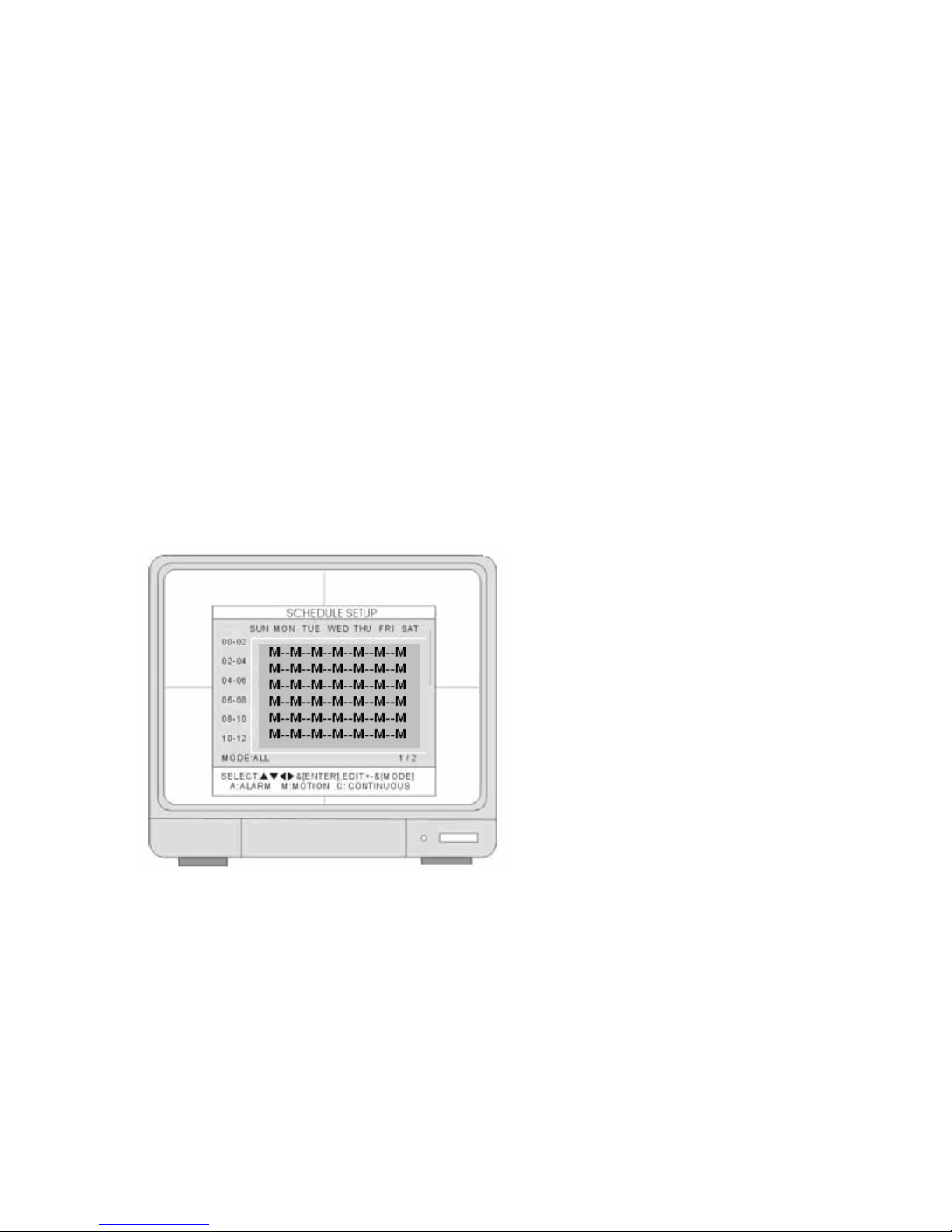
• MODE: Press MODE to select an editing mode. Continue till you see “MODE: ALL” at
bottom of screen, then press [+] and [-] to select a recording mode M.
23. Continue to press MENU to exit all menus at this time. We are done for now and your
system should be up and running. The letter M will display on your monitor indicating you
are recording in motion. Exit MENU and turn the DVR off for about 20 seconds.
THIS CONCLUDES BASIC SETUP AND YOU SHOULD BE OPERATIONAL. PLEASE
CONTIUNE READING THE USER MANUAL FOR FURTHER OPTIMAL CONFIGURATION
SETTINGS. IF YOU HAVE ANY QUESTIONS PLEASE CONTACT OUR TECHNICAL
SUPPORT GROUP AT 800-335-9777.
30
 Loading...