

Page 1
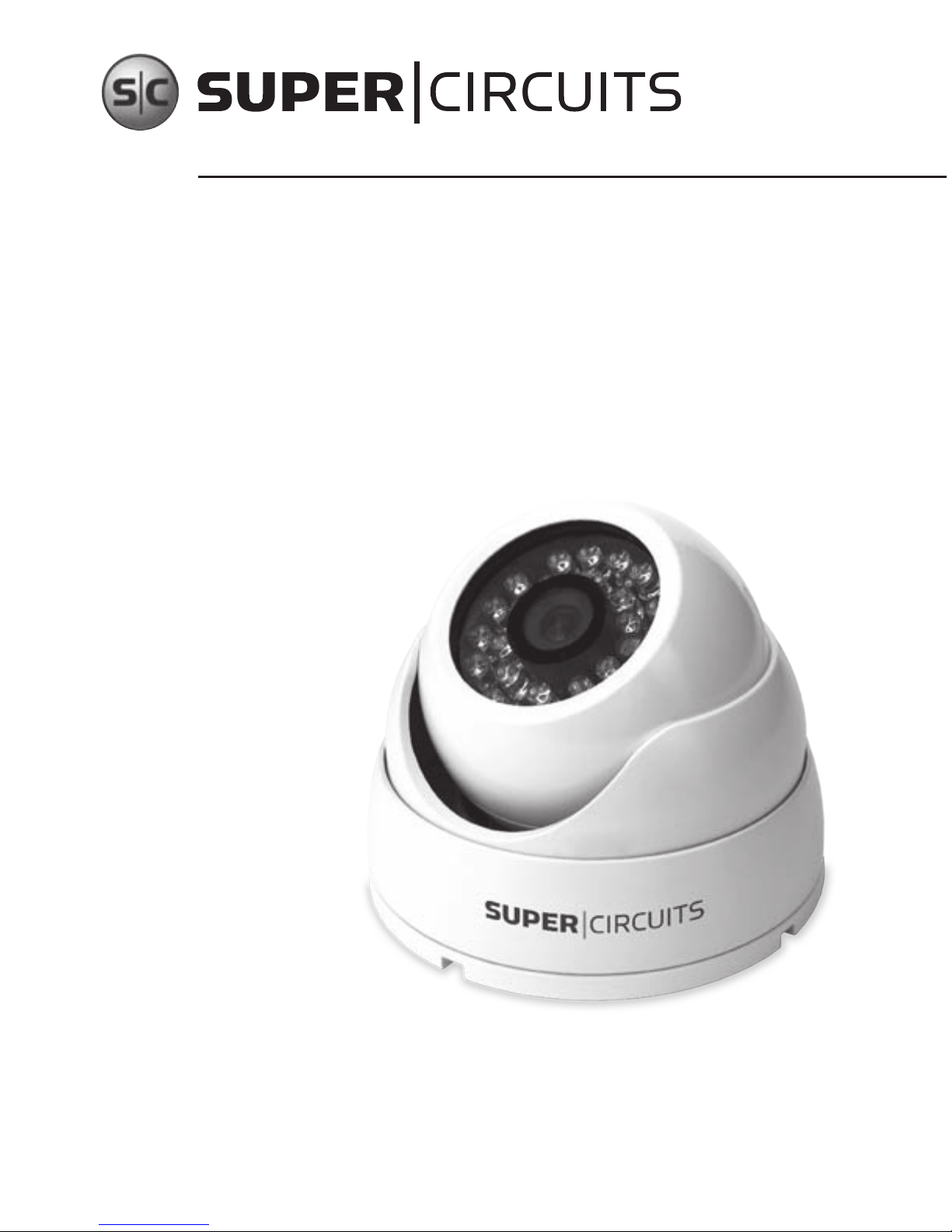
Infrared Dome CCD
Camera User Manual
Products: CD33-2, CD33VF-2, CD33VFHR-2,
CD33VFW-2, CD33W-2, CD33WHR-2
Please read this manual before installing and using this camera and always follow instructions for proper use.
Please le this manual away for future reference.
CD33-2_CM
8/9/12
Page 2

LEGAL NOTICE
Supercircuits products are designed to meet safety and performance
standards with the use of specic Supercircuits authorized accessories.
Supercircuits disclaims liability associated with the use of non-Supercircuits
authorized accessories.
The recording, transmission, or broadcast of any person’s voice without their
consent or a court order is strictly prohibited by law.
Supercircuits makes no representations concerning the legality of certain
product applications such as the making, transmission, or recording of video
and/or audio signals of others without their knowledge and/or consent. We
encourage you to check and comply with all applicable local, state, and federal
laws and regulations before engaging in any form of surveillance or any
transmission of radio frequencies.
No part of this document may be reproduced or distributed in any form or by any
means without the express written permission of Supercircuits, Inc.
© 2010, 2012 Supercircuits, Inc. All rights reserved.
Supercircuits, Inc., 1.800.335.9777 | Fax: 1.866.267.9777
11000 N. Mopac Expressway, Building 300, Austin, TX 78759
For Sales/Support, please contact your supplier.
www.supercircuits.com
WARNING
RISK OF ELECTRIC SHOCK. DO NOT OPEN.
To reduce the risk of electric shock, do not
remove cover (or back). No user serviceable
parts inside. Refer servicing to qualied
service personnel.
Page 3
iii
Infrared Dome CCD Camera User Manual
WARNINGS & CAUTIONS
WARNING
!
Do not use the camera if fumes, smoke or a strange odor is emitted
from the unit, or if it seems to not function correctly. Disconnect the
power source immediately and consult your supplier.
CAUTION
Always follow the instructions in the installation guide when
applying power. Fire and equipment damage can occur if power
is applied incorrectly. For the correct power supply, refer to the
specication sheet.
CAUTION
Do not install or operate in small, unventilated areas. Heat build up
can signicantly reduce the performance and operating life of the
product and may cause a re.
CAUTION
To prevent damage, do not drop the camera or
subject it to strong shock or vibration.
CAUTION
If installed close to a TV, radio transmitter, magnet, electric motor
transformer or audio speakers the magnetic eld generated may
interfere with or distort
the image.
Page 4
iv
www.supercircuits.com
WARNINGS & CAUTIONS
CAUTION
Whether or not the camera is used outdoors, never point it toward
the sun. Use caution when operating the camera in the vicinity of spot
lights or other bright lights and light reecting objects.
CAUTION
Do not use the camera in extreme environments where high
temperatures or high humidity exists. Use the camera under
conditions where temperatures are between -4°F ~ 122°F (-20°C ~
50°C), and humidity is below 85%.
Page 5

v
Infrared Dome CCD Camera User Manual
TABLE OF CONTENTS
Table of Contents
SECTION 1 Features . . . . . . . . . . . . . . . . . . . . . . . . . . . . . . . . . . . . . . . . . . 1
1.1 Camera components . . . . . . . . . . . . . . . . . . . . . . . . . . . . 2
1.2 Camera connections . . . . . . . . . . . . . . . . . . . . . . . . . . . . 3
SECTION 2 Installation . . . . . . . . . . . . . . . . . . . . . . . . . . . . . . . . . . . . . . . 4
2.1 What’s in the box . . . . . . . . . . . . . . . . . . . . . . . . . . . . . . . 4
2.2 Tools you need . . . . . . . . . . . . . . . . . . . . . . . . . . . . . . . . . 4
2.3 Installation instructions . . . . . . . . . . . . . . . . . . . . . . . . . 5
SECTION 3 Aiming the Camera . . . . . . . . . . . . . . . . . . . . . . . . . . . . . . . 11
SECTION 4 Cleaning . . . . . . . . . . . . . . . . . . . . . . . . . . . . . . . . . . . . . . . . 12
SECTION 5 Specications . . . . . . . . . . . . . . . . . . . . . . . . . . . . . . . . . . . . 13
SECTION 6 Troubleshooting . . . . . . . . . . . . . . . . . . . . . . . . . . . . . . . . . . 15
Tables
Table 1. Specications for
CD33W-2, CD33-2, CD33WHR-2 cameras . . . . . . . . . . . . . . . . . . . . . . . . . . . . . . . 13
Table 2. Specications for
CD33VF-2, CD33VFHR-2, CD33VFW-2 cameras . . . . . . . . . . . . . . . . . . . . . . . . . . 14
Page 6

1
www.supercircuits.com
SECTION 1: FEATURES
SECTION 1
Features
The CD33-2 series weatherproof, vandal resistant turret dome cameras are ideal for exterior
locations where surveillance in low-light environments is required. These cameras include:
• Advanced image sensors for greater picture clarity
• Precision lenses to achieve the perfect view
• The ability to see in the dark with built-in IR array
• A turret design for increased vandal resistance
Page 7
2
Infrared Dome CCD Camera User Manual
SECTION 1: FEATURES
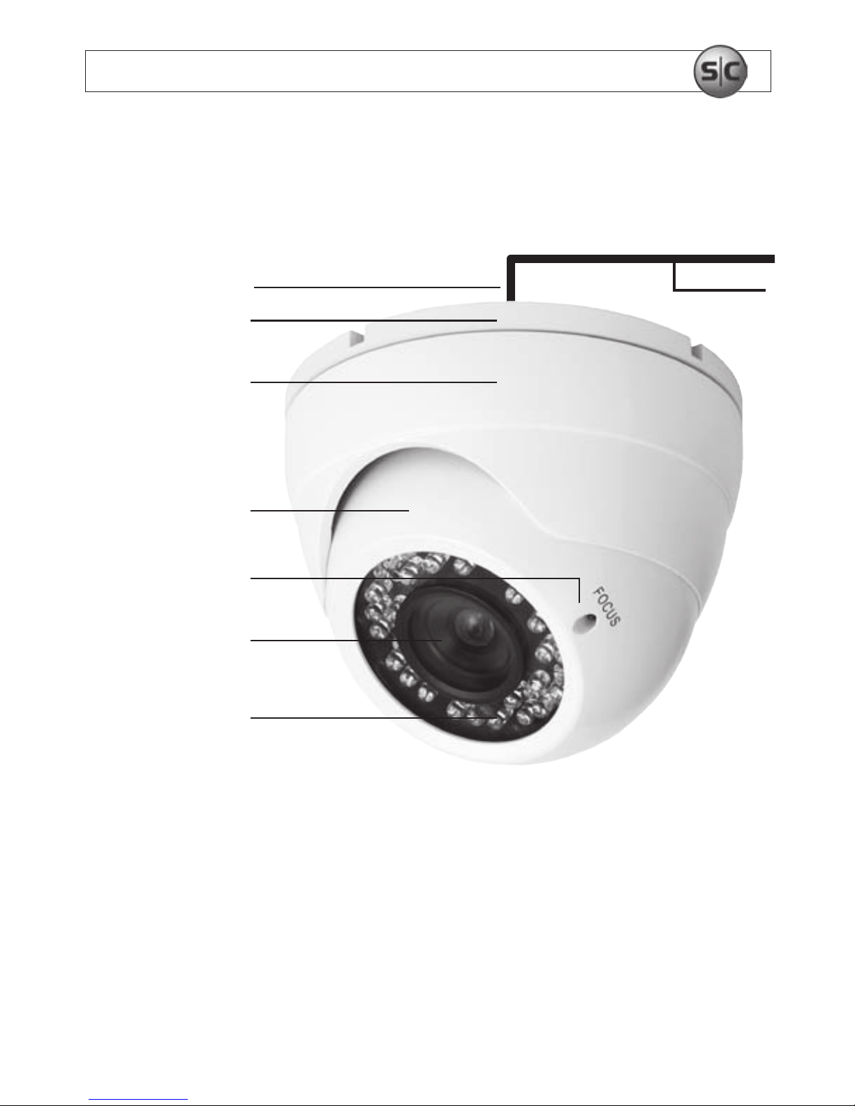
1.1 Camera components
Drop Cable
Video 75 Ohm
12 V DC
Base
Housing Bezel
Turret Style
Camera Housing
Focus Adjust
(VF Models)
Camera Lens
IR LEDs
Page 8
3
www.supercircuits.com
SECTION 1: FEATURES
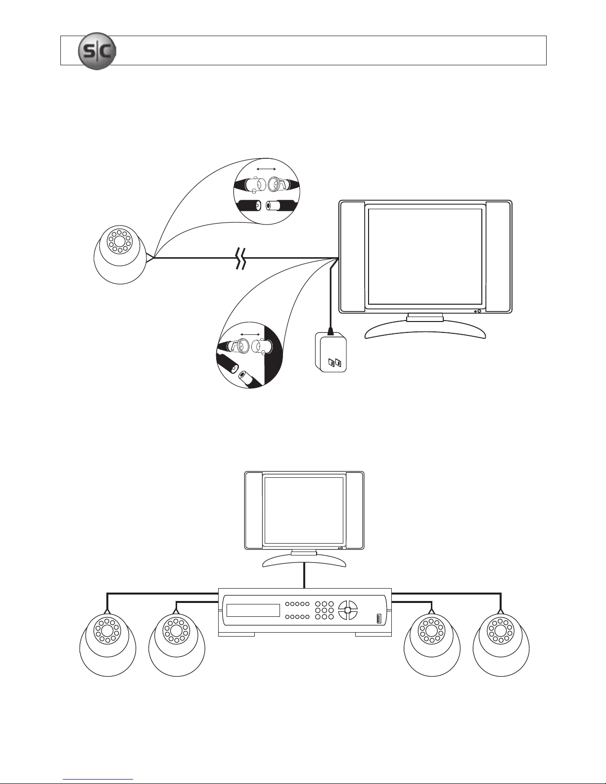
1.2 Camera connections
Single camera with monitor (above);
Multiple camera system with DVR and monitor (below)
Connect
Connect
Page 9

4
Infrared Dome CCD Camera User Manual
SECTION 2: INSTALLATION
SECTION 2
Installation
2.1 What’s in the box
The camera package contains:
• Camera assembly
• Instruction manual
• Hardware kit, including four 1" screws and four wall inserts
2.2 Tools you need
To install the camera, you will need:
• Phillips #2 screwdriver
• Small blade screwdriver (for adjusting VF model cameras)
Depending on how the camera is mounted, you may also need:
• Hammer
• Drill with 3/32" and 3/16" drill bits
• 3/4" hole saw
Page 10
5
www.supercircuits.com
SECTION 2: INSTALLATION
2.3 Installation instructions
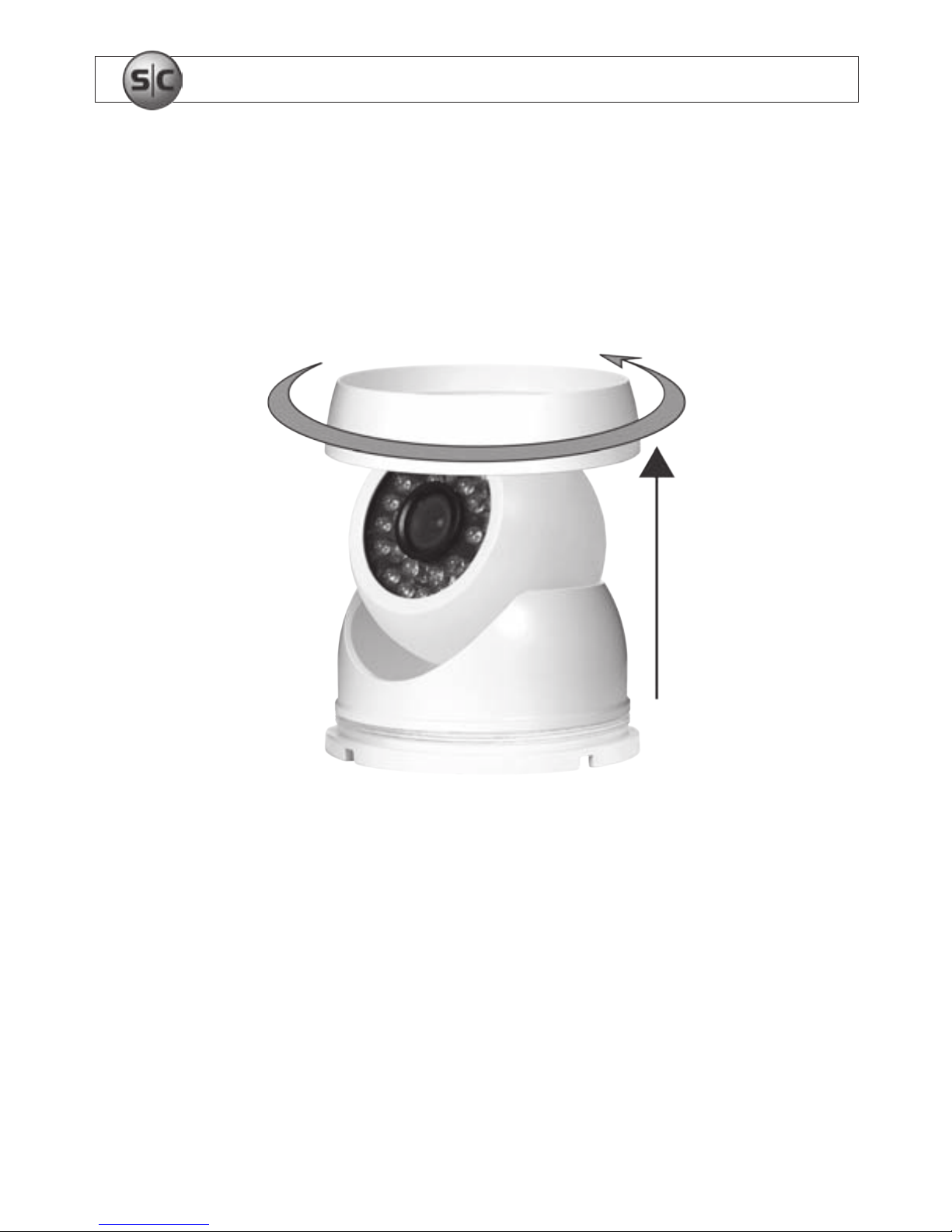
1. Separate the base from the rest of the camera assembly by unscrewing the housing
bezel.
Removal of housing bezel
2. Determine where the camera will be mounted.
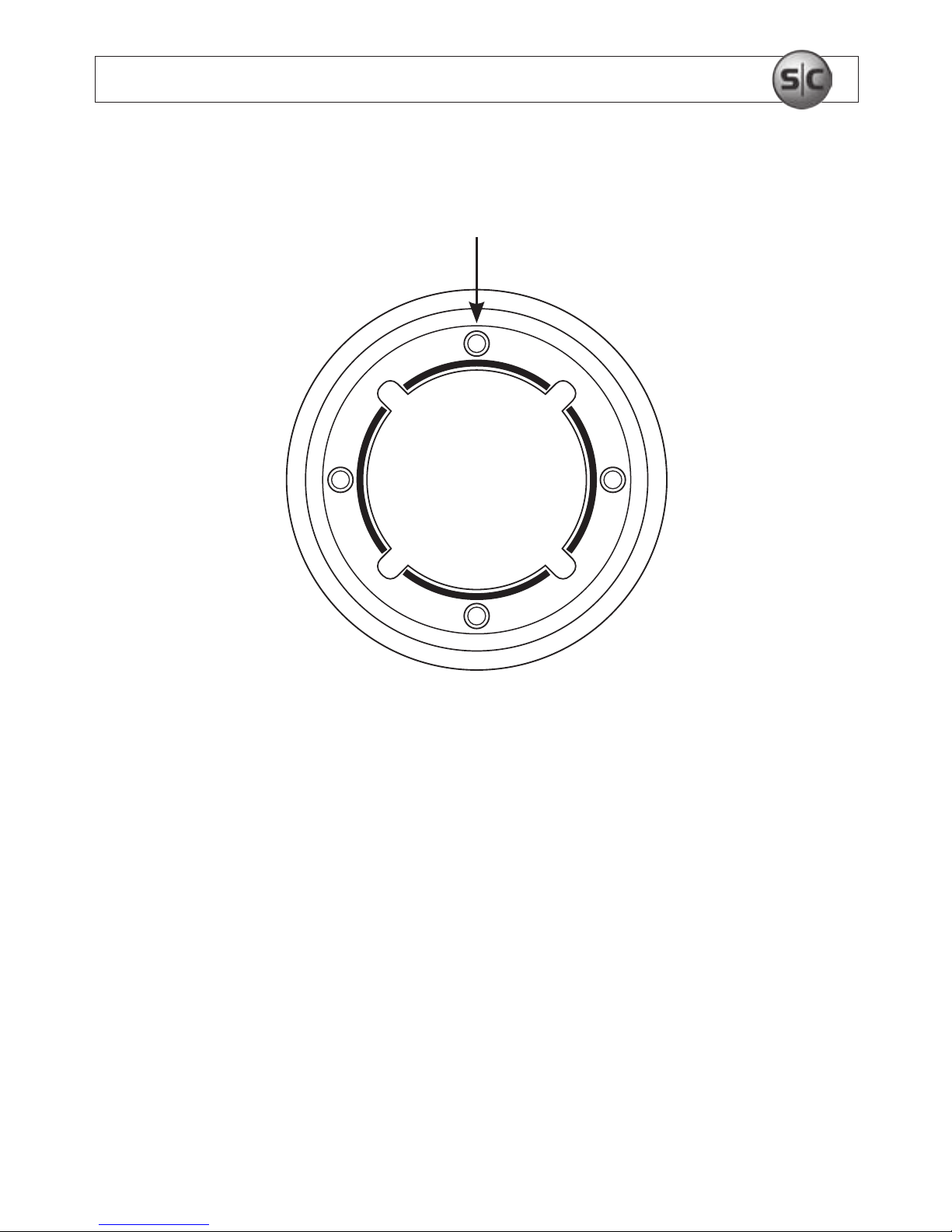
3. Using the base as a template, mark the location of the four mounting screw holes.
Page 11
6
Infrared Dome CCD Camera User Manual
SECTION 2: INSTALLATION
Camera base
4. Drill mounting screw holes into the mounting surface.
a. If the mounting surface is a soft material, such as a drywall, use a 3/16" bit to
drill the mounting holes. Use a hammer to tap the wall inserts provided into
each hole until they are ush with the surface.
OR (continued on next page)
Mounting Screw
Holes
Page 12
7
www.supercircuits.com
SECTION 2: INSTALLATION
b. If the mounting surface is a very soft material, such as ceiling tile, place a wood
block behind the tile. Screws longer than 1" may be required. Drill holes for the
mounting screws through the surface and into the wood block.
OR
c. If mounting the camera on a harder surface, such as wood, drill the mounting
screw holes with a 3/32" bit.
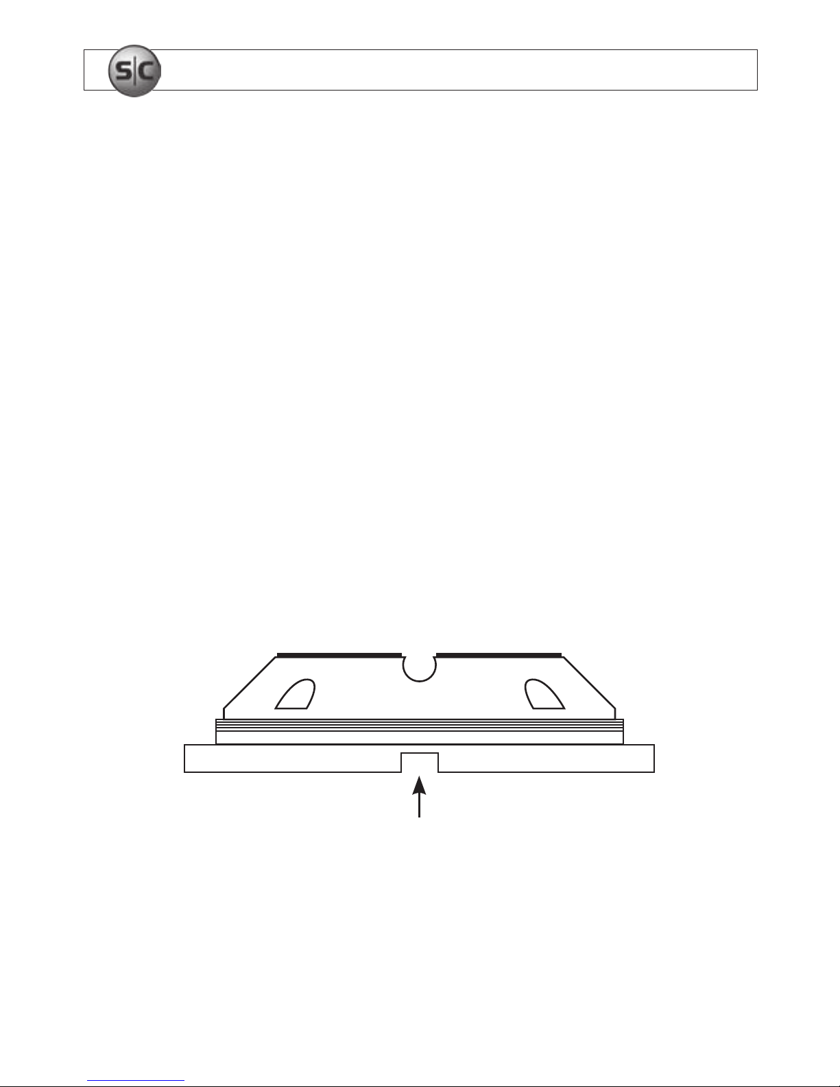
5. Determine the cable routing. If the cable is to be routed through a hole in the
mounting location within the coverage of the base, perform the following steps. If
the cable will be routed through a cable guide in the base, skip to step 9.
Cable Guide
in Base
Page 13
8
Infrared Dome CCD Camera User Manual
SECTION 2: INSTALLATION
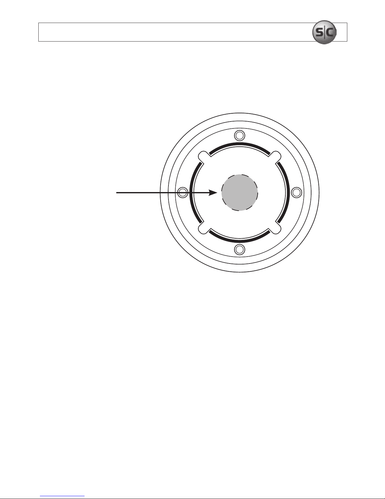
6. Drill a 3/4" hole through the mounting surface at the center
of the base.
7. Use a #2 Phillips screwdriver to mount the base with the
provided screws.
8. With the camera in the camera housing, route the drop cable through the 3/4" hole
until the camera housing is tted onto the base. Place the housing bezel over the
camera housing and screw it onto the base until the camera and camera housing are
held in place. Skip to step 12.
3/4" Cable
Routing Hole
Page 14
9
www.supercircuits.com
SECTION 2: INSTALLATION
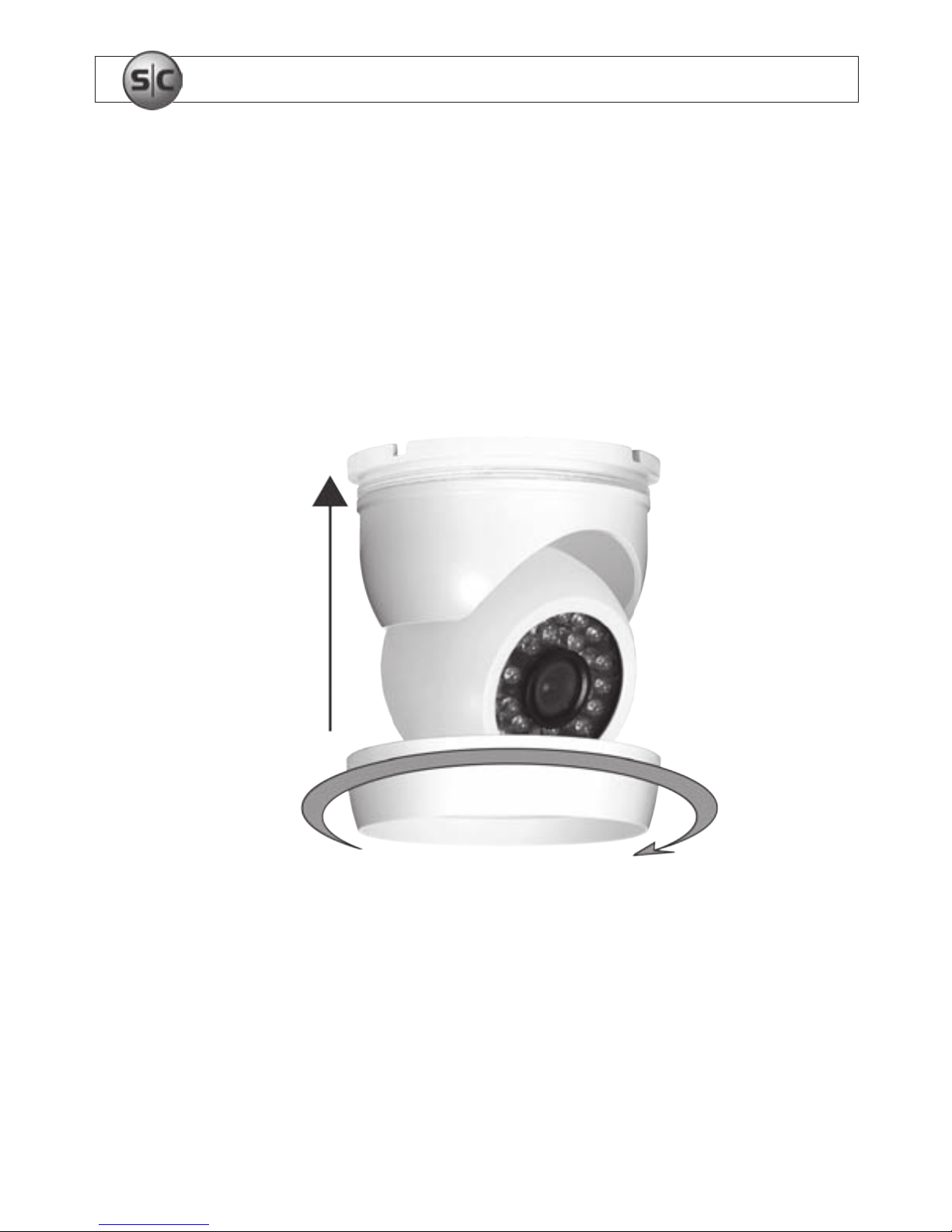
9. Set the camera on the base with the camera cable pressed into one of the cable
guides of the base. Allow some slack in the cable within the base to allow for
camera positioning later.
10. Use a #2 Phillips screwdriver to mount the base with the
provided screws.
Tighten housing bezel
Page 15
10
Infrared Dome CCD Camera User Manual
SECTION 2: INSTALLATION
11. Without allowing the camera to hang by the drop cable, place the camera housing
with the housing bezel over the camera and t it onto the base. Screw the housing
bezel onto the base until the camera and camera housing are held in place.
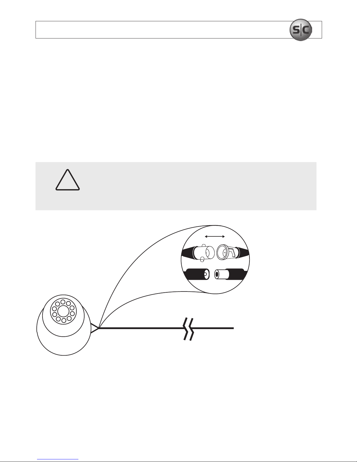
12. Attach the BNC video/power cable to the camera cable
as required.
CAUTION
Notice that power connectors on the BNC video/power cable are
dierent at each end!
Cable attachment
Connect
To DVR/Monitor
and Power
To DVR/Monitor
and Power
Page 16

11
www.supercircuits.com
SECTION 3: AIMING THE CAMERA
SECTION 3
Aiming the Camera
1. Connect the video cable from the camera to (a test monitor or to) the BNC input on
the DVR.
2. Connect the DC12V adapter to the camera.
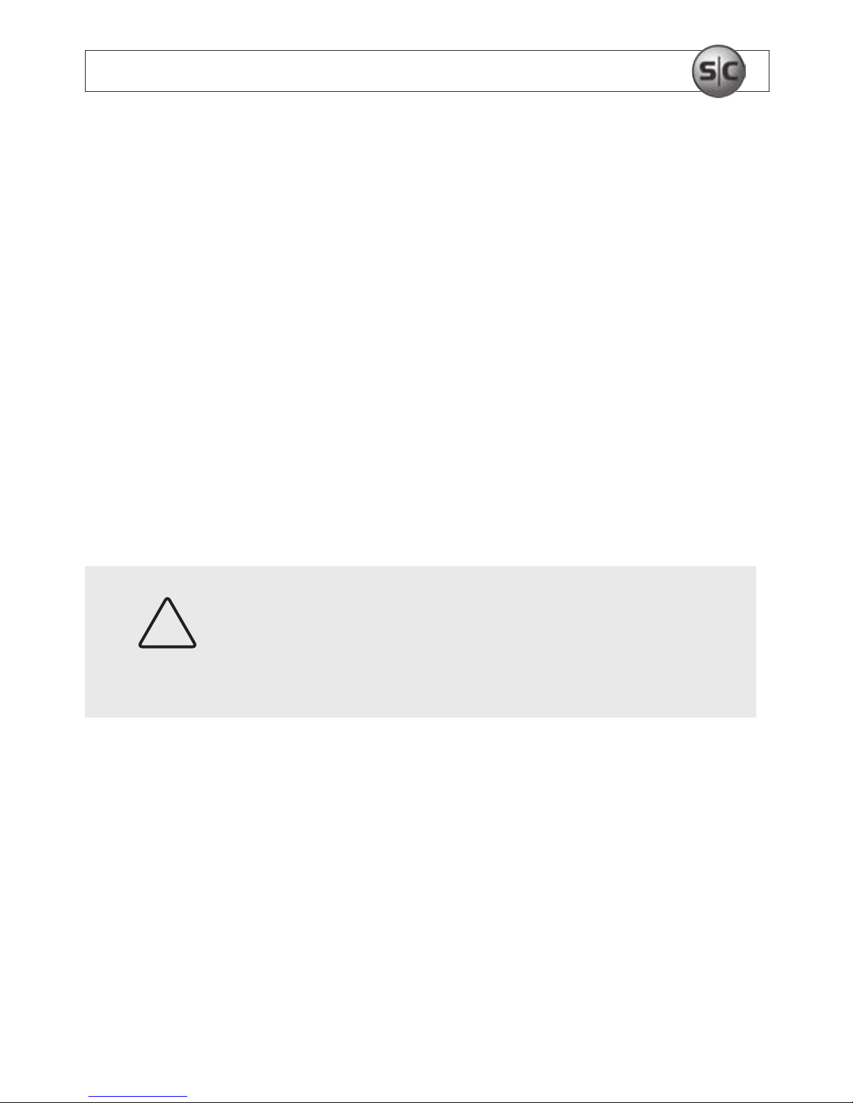
3. Loosen the housing bezel until the housing can be rotated on
the base.
4. While observing the video from the camera, rotate the camera housing and/or tilt
the camera within the housing to point it at your surveillance target.
5. Tighten the housing bezel to hold the camera in place.
6. If you have a CD33VF-2, CD33VFW-2, or CD33VFHR-2 camera, use a small blade
screwdriver to adjust the focus and zoom if necessary.
Page 17
12
Infrared Dome CCD Camera User Manual
SECTION 4: CLEANING
SECTION 4
Cleaning
Clean the camera lens and IR lamp shield with an approved glass cleaning solution and a
lint free cloth.
• Dust can be removed from the unit by wiping it with a soft damp cloth. To remove stains,
gently rub the surface with a soft cloth moistened with a mild detergent solution, then rinse
and dry it with a soft cloth.
• Remove all foreign particles, such as plastic or rubber materials, attached to the camera
housing. These may cause damage to the surface over time.
CAUTION
Do not use benzene, thinner or other chemical products on the
camera assembly; these may dissolve the paint and promote
damage of the surfaces. Before using any chemical product, read
the accompanying instructions carefully.
Page 18
13
www.supercircuits.com
SECTION 5: SPECIFICATIONS
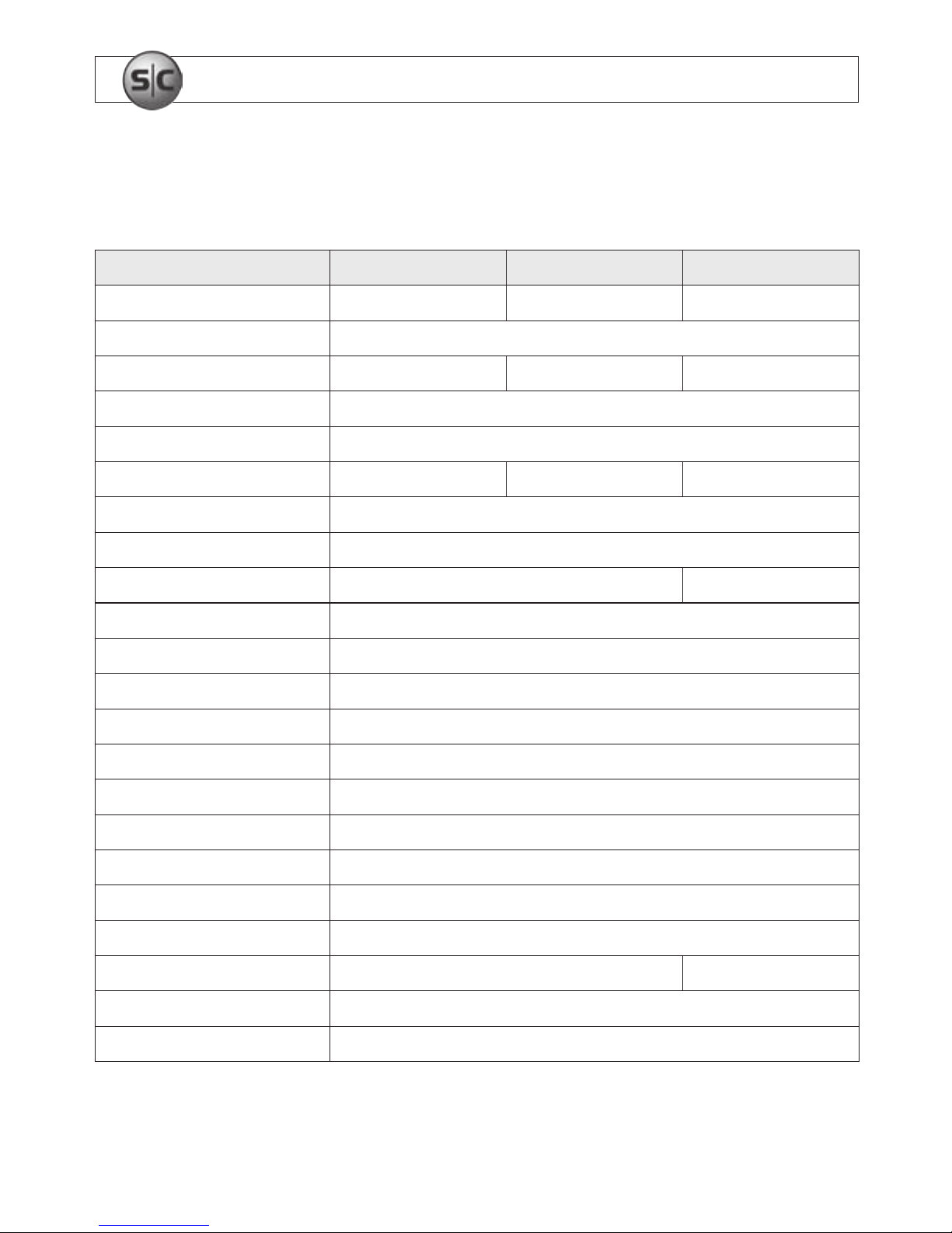
Table 1. Specications for CD33W-2, CD33-2, CD33WHR-2 cameras
Model CD33W-2 CD33-2 CD33WHR-2
Image Sensor 1/4" Sharp CCD 1/4" Sharp CCD 1/3" SONY CCD
TV system NTSC
CCD total pixels 537 (H) x 505 (V) 537 (H) x 505 (V) 811 (H) x 508 (V)
Scanning system 525 Lines, 60 elds/s
SYNC system Internal
Horizontal resolution 420 TV lines 420 TV lines 540 TV line
Minimum illumination 0 lux / F2.0 (LED on)
Lens Standard 3.6 mm lens
IR range 50 ft (15.24 m) 65 ft (19.81 m)
Infrared status Under 10 lux by CDS Auto Control
B.L.C. control Auto
White balance Auto
Gain control Auto
Electronic shutter 1/60 ~ 1/120,000 s
S/N ratio >48 dB (AGC o)
Gamma correction >0.45
Video output 1.0 Vp-p / 75
Operating temp. -4 °F ~ 122 °F (-20 °C ~ 50 ° C)
Operating humidity Below 85% RH
Power supply 12 Vdc (±10%) 230 mA 12 Vdc 320 mA
Dimensions 3.7 in (D) x 3.25 in (H) (94 mm (D) x 68.5 mm (H))
Weight-Net (g) Approx. 1 lb (450 g)
Page 19
14
Infrared Dome CCD Camera User Manual
SECTION 5: SPECIFICATIONS
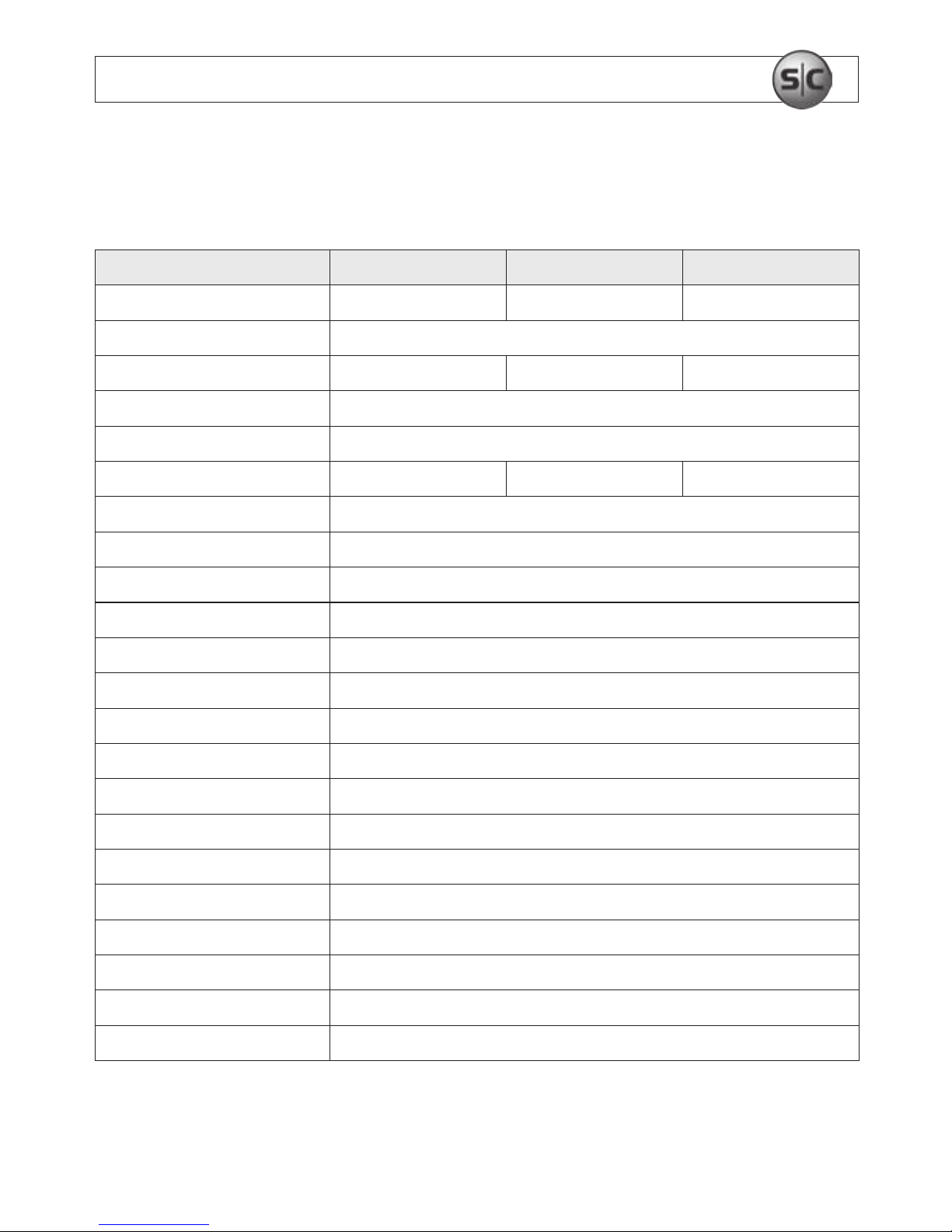
Table 2. Specications for CD33VF-2, CD33VFHR-2, CD33VFW cameras
Model CD33VFW-2 CD33VF-2 CD33VFHR-2
Image Sensor 1/3" SONY CCD 1/3" SONY CCD 1/3" SONY CCD
TV system NTSC
CCD total pixels 537 (H) x 505 (V) 537 (H) x 505 (V) 811 (H) x 508 (V)
Scanning system 525 Lines, 60 elds/s
SYNC system Internal
Horizontal resolution 420 TV lines 420 TV lines 540 TV lines
Minimum illumination 0 lux / F2.0 (LED on)
Lens 4 ~ 9 mm varifocal lens
IR range 90 ft (27.43 m)
Infrared status Under 10 lux by CDS Auto Control
B.L.C. control Auto
White balance Auto
Gain control Auto
Electronic shutter 1/60 ~ 1/120,000 s
S/N ratio >48 dB (AGC o)
Gamma correction >0.45
Video output 1.0 Vp-p / 75
Operating temp. -4 °F ~ 122 °F (-20 °C ~ 50 °C)
Operating humidity < 85% RH
Power supply 12 Vdc (±10%) 320 mA
Dimensions 4.69 in (D) x 3.25 in (H) (119 mm (D) x 68.5 mm (H))
Weight-Net (g) Approx. 3 lb (1361 g)
Page 20

15
www.supercircuits.com
SECTION 6: TROUBLESHOOTING
SECTION 6
Troubleshooting
Before sending the camera for repair, please check below to make sure that the camera is
installed correctly. If it still does not perform adequately, please consult your supplier.
1. No picture on the monitor screen.
a. Check that all connected devices are powered on.
b. Conrm that the voltage is correct.
c. Conrm that the power supply provides enough current
to power the camera.
d. Check that all video cables are correctly connected.
2. The picture is not clear.
a. Check that your monitor is correctly adjusted.
b. Conrm that the glass in front of the lens is clean.
If there is dust, dirt or ngerprints on the glass, the image
quality will be aected. To clean the glass use a soft, dry
and non-abrasive cloth or a commercially available lens cleaning set.
c. Correctly adjust the focus (varifocal models only.)
Page 21
16
Infrared Dome CCD Camera User Manual
SECTION 6: TROUBLESHOOTING
3. The picture has interference.
a. The camera may be close to a high voltage source,
such as a power generator.
b. The BNC cable is not terminated properly.
c. The video cables are not connected properly.
CAUTION
This camera is a precision instrument and when treated with care,
will provide years of satisfactory performance. If a problem does
occur, do not open the camera to make repairs. Servicing should
always be referred to your supplier.
Page 22

Page 23

Page 24

 Loading...