

Super Circuits AVSI-12 Setup And User Manual
AVSI-12 Interview Room System
Setup and User Guide
PLEASE READ THIS MANUAL BEFORE USING YOUR SYSTEM, and always follow the
instructions for safety and proper use. Save this manual for future reference.
AVSI-12_SM
170322

CAUTION
Operate this system onl y in environments where the temperature and h umidity is within the recommend ed range. Operation in
temperatures or at hum idity levels outside the recommen ded range may cause electric shock and sh orten the life of the produc t.
Refer to the specicati ons for each system component fo r more information.
LEGAL NOTICE
Supercircuits products are designed to meet safety and performance standards with the use of specic
Supercircuits authorized accessories. Supercircuits disclaims liability associated with the use of non-Supercircuits
authorized accessories.
The recording, transmission, or broadcast of any person’s voice without their consent or a cour t order is strictly
prohibited by law.
Supercircuits makes no representations concerning the legalit y of certain product applications such as the
making, transmission, or recording of video and/or audio signals of others without their knowledge and/or
consent. We encourage you to check and comply with all applicable local, state, and federal laws and regulations
before engaging in any form of surveillance or any transmission of radio frequencies.
Microsoft, Windows, and Internet Explorer are either registered trademarks or trademarks of Microsoft Corporation in
the United States and/or other countries. Android is a trademark of Google Inc. Use of this trademark is subject to
Google Permissions. Apple, iPhone, iPod to uch, and iPad are registered trademarks of Apple Inc.
Other trademark s and trade names may be used in this document to refer to either the entities claiming the marks
and names or their products. Supercircuits, Inc. disclaims any proprietary interest in trademarks and trade names
other than its own.
No part of this document may be reproduced or distributed in any form or by any means without the express written
permission of Supercircuits, Inc.
© 2017 Observint Technologies. All rights reserved.
11000 N. Mopac E xpressway, Building 300, Austin, TX 78759
For Sales and Support, please contact Supercircuits.
ii
www.Observint.com

PRELIMINARY
TABLE OF CONTENTS
Table of Contents
SECTION 1 Systems Overview ...................................................................1
1.1 System components ..................................................................2
1.2 Optional equipment ..................................................................6
1.3 Optional camera .....................................................................7
SECTION 2 Getting Started ..................................................................... 9
2.1 Unpacking the equipment .............................................................9
2.2 What you need ......................................................................9
SECTION 3 System Setup ......................................................................10
3.1 Install the recorder hardware .........................................................10
3.2 Mount and wire the AVSI switch .......................................................11
3.3 Connect the CAB-SWITCH cable to the recorder alarm terminals and to 12 Vdc power ..........13
3.3.1 Test the AVSI switch .............................................................15
3.4 Connect the speakers to the recorder ...................................................16
3.5 Install the ALI-TS1012R camera and PA3 microphone .....................................16
3.6 Powering on the system for the rst time ..............................................18
SECTION 4 Test/Use the Interview Room System ................................................. 31
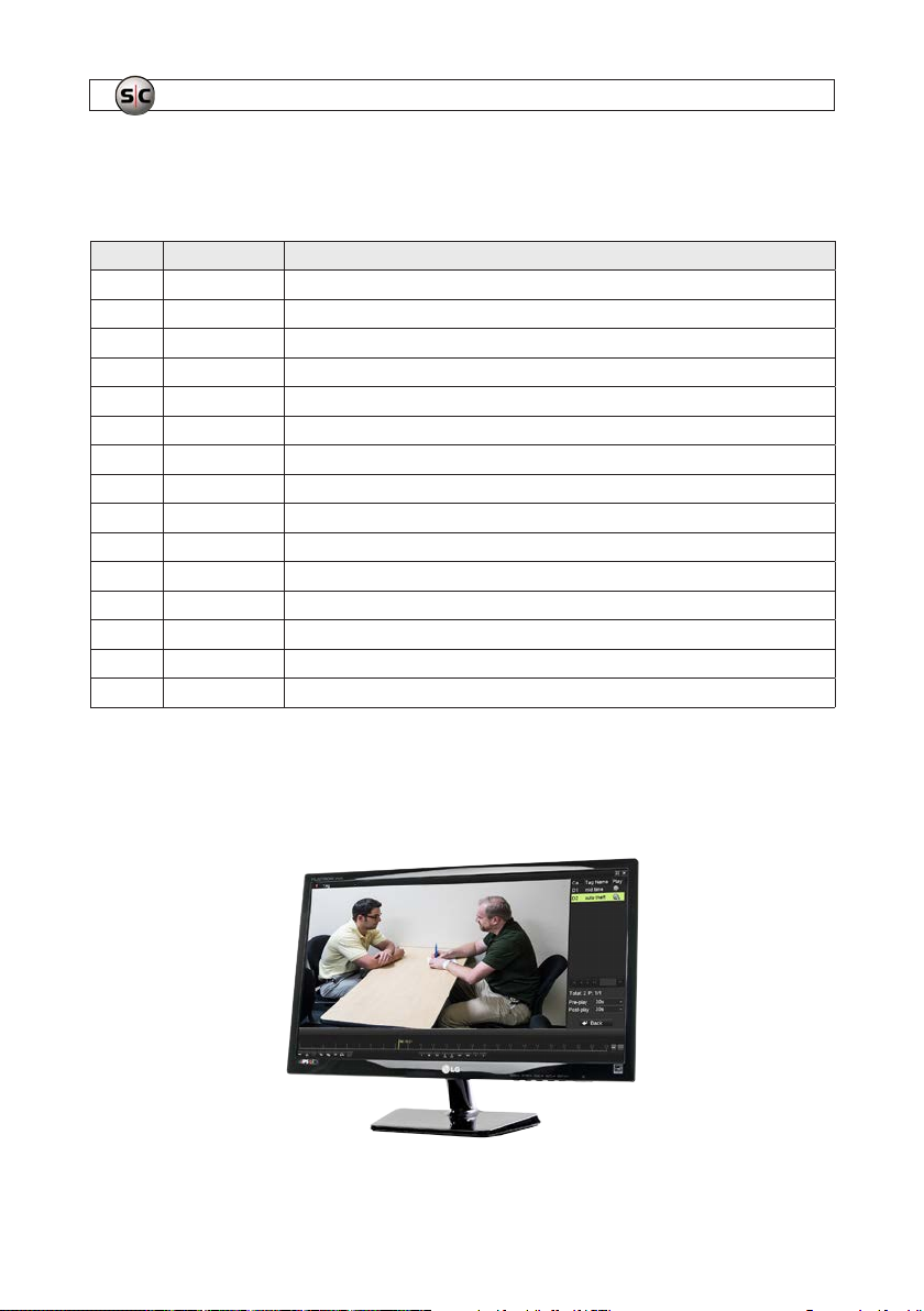
4.1 Playback recorded video .............................................................32
4.2 Tagging recorded video ..............................................................36
4.2.1 Search for and Playback a Tag ....................................................38
4.3 Export recorded video ...............................................................39
4.3.1 Export video during playback .....................................................39
4.3.2 Using the Export menu to locate and export video les ...............................43
4.4 Manual recording ...................................................................50
SECTION 5 Advanced Recorder Features ......................................................... 51
5.1 User Management ..................................................................51
5.2 Network Setup .....................................................................52
5.3 Remote Access ......................................................................52
5.4 System Maintenance ................................................................53
iiiAVSI-12 Interview Room System Setup and User Guide

NOTES
iv
www.Observint.com
SECTION 1: SYSTEM OVERVIEW
SECTION 1
Systems Overview
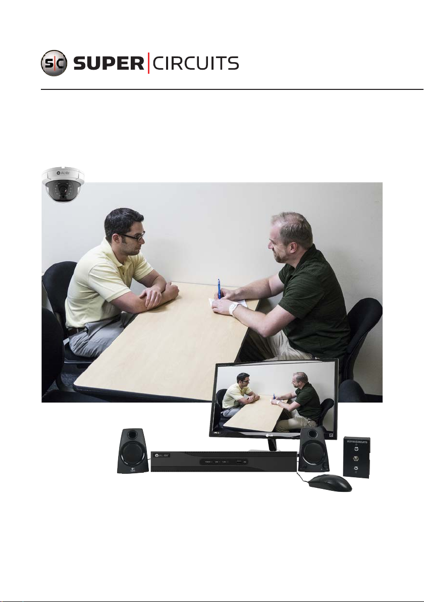
The AVSI-12 Interview Room sys tem is a premium quality scalable vide o and audio digital recording system ideally suited for indoor
installation in rooms where inter views or interrogations occur. The digital recording system allows you to searc h and playback live
video and audio, and export re cordings locally or download them remotely. Additionally, you can expand the system to monitor and
record up to 4 interview rooms simult aneously.
The Interview Room System is pre congured to record the video received on (A1) Camera 01 (Video In 1) and the audio on Audio
In (1) when the AVSI switch is on. When this happens, the Live View display for channel 1 is expanded to full screen.
The recorder can b e networked on a LAN and congured for remote access, providing live view, playback , download and manual
recording capabilities.
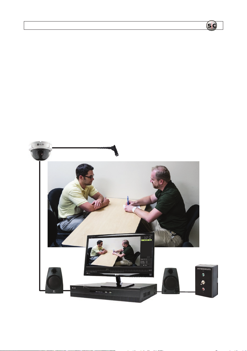
ALI -TS1012R camera
PA3 microphone
AVSI-SPEAKER
speakers
ALI-QVR4008H recorder
AVSI-12 System Components
23LGL ED2
monitor
AVSI -SW1
switch
1AVSI-12 Interview Room Switch Systems Setup Guide
SECTION 1: SYSTEM OVERVIEW
1.1 System components
The interview room system components include:
Quantity SKU Description
1 23LGLE D2 LG™ 23” 1080 p Full-HD Wide screen Commer cial Grade LED M onitor
1 ALI-QVR4008H1TB Alibi 4 000 series 8 -channel HD -TVI Hybrid+ se curity DVR
1 ALI -TS1012R HD-TVI 2M P indoor dome ca mera
1 AUDIOADAPTER Mono audi o 3.5mm female to RCA m ale adapter
1 AVSI-SPEAKER Powered stereo speaker set
1 AVSI-STEREO Adapter cable
1 AVSI-SW1 AVSI system c ontrol switc h
1 CAB-SWITCH 4 -wire cable
1 CON-5 Female RCA to female RCA adapter
1 DC12-1000R 12 Vdc 1A power a dapter
1 DC12-2000R 12 Vdc 2A po wer adapter
1 EX T65 65 ft Vid eo/Audio/Power ex tension cable
1 FEMALE-POW Female power lead
1 PA3 Super high gain micro audio system microphone
1 YPOWER Single female to dual power adapter
23LGLED2 Monitor
This 23 inch (23 in diagonal) LED monitor deliver s 1920 x 1080 (1080p) full-HD video resolution and features a non-glare 16:9
aspect ratio and 178° × 178° viewing angle.
2
www.Observint.com
SECTION 1: SYSTEM OVERVIEW
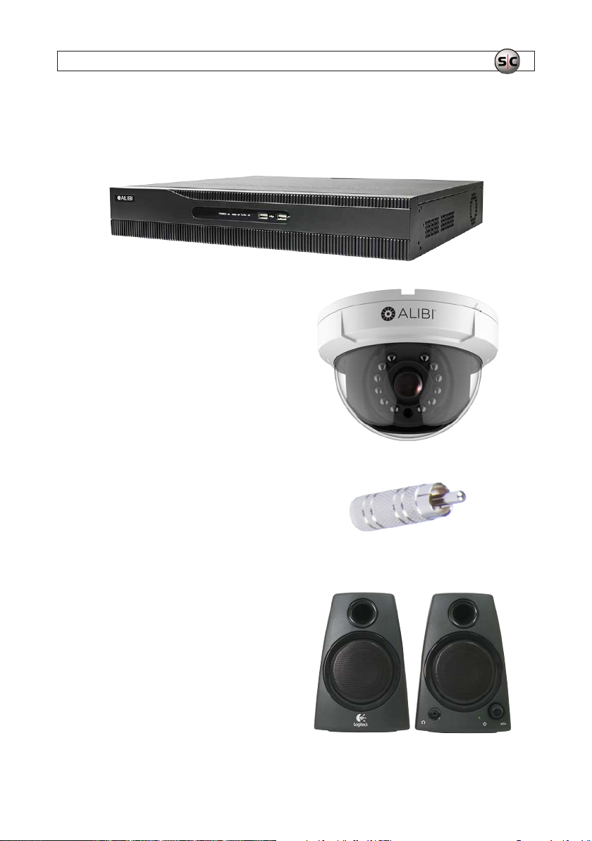
ALI-QVR4008H1TB Recorder
The Alibi ALI-QVR4008H hybrid+ digital video recorder supp orts 1080p HD-TVI, analog and IP c ameras and includes a precongured 1TB HDD. It can be contain up to two HDDs, each with a capaci ty of 8TB for a maximum system c apacity of 16TB.
ALI-TS1012R Camera
The ALIBI ALI-TS1012R HD-TVI 2MP indoor dome camera
include a new generation sensor wi th high sensitivity and
advanced circuit design technology. It feature low image
distort ion and low noise which makes them suitable for
surveillance and image processing systems.
AUDIOADAPTER
Converts 3.5 mm plug go RCA male.
AVSI-SPEAKER Speakers
The AVSI-SPEAKER is a high quality computer compatible
powered stere o speaker set. It connects to t he audio out jack on
the back of the ALI -QVR4008H recorder.
3AVSI-12 Interview Room System Setup and User Guide
SECTION 1: SYSTEM OVERVIEW
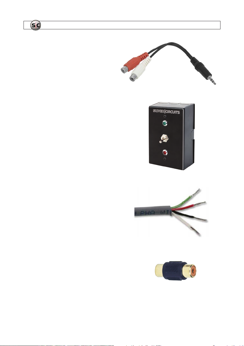
AVSI-STEREO adapter cable
RCA audio lef t and right to 3.5 mm stereo connec tor adapter
cable.
AVSI-SW1 system contro l switch
The AVSI-SW is a simple ush-mountable interview ro om switch
assembly that can be used to start and stop recording equipment
with a single toggle of the switch. The switch is designed to t into
a 1-gang electrical box. All ter minations to the switch are on the
inside on the back of t he box.
CAB-SWITCH cable
T00 ft 4-wire shielded cable for 12 Vdc power and switch interdevice wiring.
CON-5 adapter
The CON-5 is a female RCA to female RCA adapter.
4
www.Observint.com
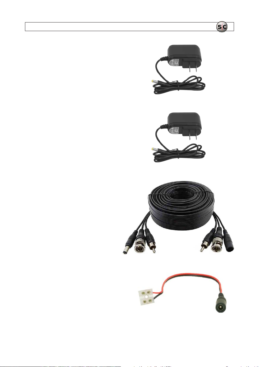
DC12-1000R 12 Vdc power adapter
The DC12-1000R is a re gulated 12 Vdc 1 amp (1000 mA)
power adapter. This power adapter is used to power the
AVSI-SW1 switch.
DC12-2000R 12 Vdc power adapter
The DC12-1000R is a re gulated 12 Vdc 2 amp (2000 mA)
power adapter. This power adapter is used with the YPOWER
splitter to power the camera and the microphone.
EXT65 65 ft Video/Audio/Power extension cable
The EXT65 features:
• 65 ft Video, Audio & Power Cable
• HD-TVI, HD-SDI, AHD, HD-CVI, 960H and HD AVS
• BNC Video Connection, RCA Audio Connection
• 2.1 x 5.5mm Power Connector (Standard)
SECTION 1: SYSTEM OVERVIEW
FEMALE-POW Power cable
EZ-Connect power cable with plug for use with t he
DC12-1000R power adapter.
5AVSI-12 Interview Room System Setup and User Guide
SECTION 1: SYSTEM OVERVIEW
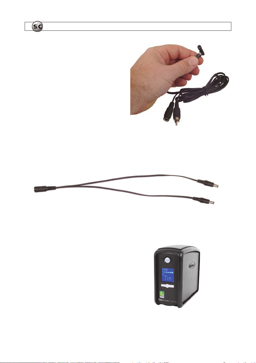
PA3 Super high gain micro audio system microphone
The PA3 high gain super mini preamp and microphone is one of
the smallest and best in the world. The built-in preamp feat ures
low noise, high gain and auto level adjustment by on-board IC,
and line level output. This microphone comes with a six foot
microphone lead plug and play cable with RC A connections. It
weighs under 1/2 ounce and provide s a line level output.
YPOWER Single female to dual male power adapter
The YPOWER adapter is used to split power on t he EXT65 video/audio/power extension cable to the camera and mic rophone. Power
on the cable is provided by the DC12-2000R power adapter at the re corder end.
1.2 Optional equipment
UPS-1000 Uninterruptible power supply (UPS)
The highly recommended UPS-1000 features 890 /1080
Joules of surge prote ction, and provides bat tery backup during
power outages. It includes automatic voltage regulation
for inconsistent utilit y power, automatically increasing or
decreasing input voltage to a consistent 110 Vac ~ 120 Vac
output. Integrate d batteries provide power when the incoming
voltage drops below 90 Vac or increases above 140 Vac.
The UPS is used to distribute p ower to the recorder, monitor,
AVSI switch, camera and audio base station.
6
www.Observint.com
SECTION 1: SYSTEM OVERVIEW
1.3 Optional camera
You can upgrade your sys tem to include any of the following cameras:
SKU Description
ALI-TP and AL I-TS series came ras A LI-TP and ALI-TS came ras oer a wide r ange of turret , bullet and dome c ameras compat ible with the AVSI-12 sys tem.
ALI -CC1 Covert c amera - Alibi 2.2 Me gapixel 1080p H D-TVI 40’ IR Wi de Angle Corner M ount Securi ty Camera
ALI- CC2 Covert camera - A libi 2.2 Megapix el 1080p HD-TVI 9 40 nm 40’ IR PIR S ensor Color Hid den Camera
ALI -CC4 Cover t camera - Alib i 2.4 Megapixel 1080 p HD-TVI, AHD, CVB S Smoke Detec tor Securit y Camera
ALI- CC5 Covert camera - A libi 2.4 Megapixel 10 80p HD-TVI, AHD, C VBS Wall Clock Sec urity Came ra
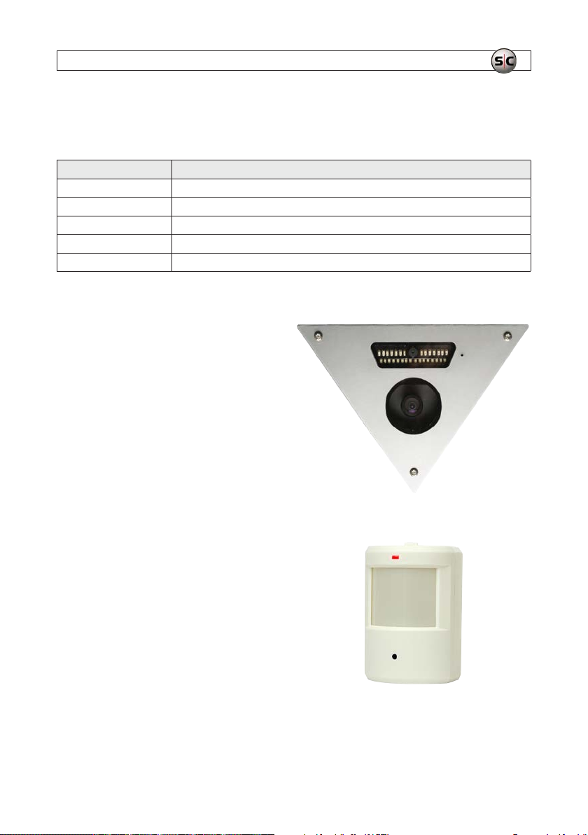
ALI-CC1
The Alibi 2.2 Megapixel 1080p HD-TVI 4 0’ IR Wide Angle Corner
Mount Security Camera c aptures sharp, detailed full-HD video.
This camera feat ures a 2.9 mm wide angle megapixel lens to
capture a wide view of larger areas.
The wide angle corner mount camera is id eal for monitoring
entryways, or anywhere a commanding view of an entire room is
required to be vie wed, and activity recorded.
ALI-CC2
Capture high resolution cover t video day and night with the
ALI-CC2 Alibi 2.2 Me gapixel 1080p HD-TVI 940 nm 40" IR PIR
Sensor Hidden Camera. This camer a features a 3.7 mm wide angle
megapixel lens to capture a wide view of larger areas.
The hidden camera is ideal for monitoring hallways, entr yways,
open areas, interview rooms or any where a commanding view of
an entire room is required to be viewed, and activity recorde d.
7AVSI-10 Interview Room Systems Setup Guide
SECTION 1: SYSTEM OVERVIEW
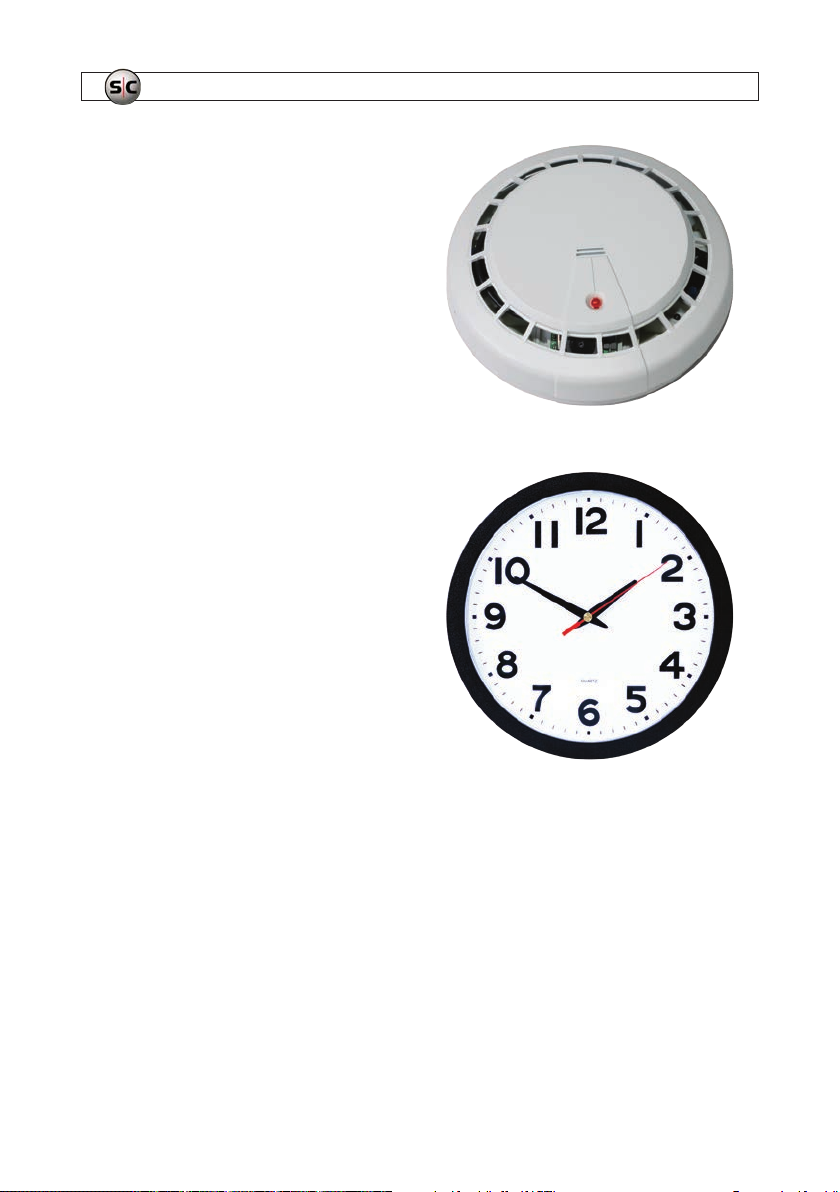
ALI-CC4
This covert smoke detector camera is equipped with a 2.4MP Sony
Progressive Sc an Sensor that delivers clear, crisp 1080p video at
30 fps. Additional features inc lude D-WDR (Digital Wide Dy namic
Range) and 3D- and 2D-DNR (Digital Noise Reduction) that further
contribute to it s exceptional quality images, even in low-light
conditions.
When used alone, the 4.3 mm wide angle lens in this camera
oers a 90 -degree Field of View, or you can achieve a f ull
360-de gree view when you add up to 3 additional cameras (ALICC4XC) within the smoke detector.
ALI-CC5
This covert wall clo ck is an unexpected sur veillance solution with a
hidden camera that’s nearly undetec table, which makes it perfect
for any residential, school, warehouse or oce application.
The day/night wall clock incorporates DWDR (Digital Wide
Dynamic Range) and 2D- and 3D-DNR (Digital Noise Reduc tion)
as well as high-resolution day/night 2.4MP Sony Progressive Scan
Sensor to produce e xceptional quality images – 1080p @ 30 f ps.
The 4.3 mm wide angle lens provides a 90 -degree eld of view.
8
www.Observint.com

SECTION 2: GETTING STARTED
SECTION 2
Getting Started
2.1 Unpacking the equipment
Remove the equipment from its p ackaging and place it on a at, clean surf ace. Inspect each item. If any visible damage is present,
contact your supplier for a replacement . Verif y that your order is complete. Within your order you should nd one of each of the
following:
• 23LGLED2: LG™ 23” 1080p Full-HD widescreen commercial grade LED monitor
• ALI-QVR4008H1TB: Alibi 4000 serie s 8-channel HD-TVI Hybrid+ security DVR
• ALI-TS1012R: HD-TVI 2MP indoor dome camera
• AUDIOADAPTER: Mono audio 3.5mm female to RC A male adapter
• AVSI-SPEAKER: Powered stereo speaker set
• AVSI-STEREO: Adapter cable
• AVSI-SW1: AVSI system control switch
• CAB-SWITCH: 4-wire cable
• CON-5: Female RCA to female RCA adapter
• DC12-1000R: 12 Vdc 1A power adapter
• DC12-2000R: 12 Vdc 2A power adapter
• EX T65: 65 ft Video/Audio/Power extension cable
• FEMALE-POW: Female power lead
• PA3: Super high gain micro audio s ystem microphone
• YPOWER: Single female to dual power adapter
NOTE
This system may be ship ped in several cartons.
2.2 What you need
• #2 Phillips screw driver
• Thin blade screwdriver
• 5/64” hex wrench
• Wire stripping tool (to strip 22 ga wire)
• Tools for installing the c amera and microphone
9AVSI-12 Interview Room System Setup and User Guide
SECTION 3: SYSTEM SETUP
SECTION 3
System Setup
The basic Inter view Room System system includes an ALI-QVR4 008H Alibi HD-TVI digital vide o recorder, an HD-TVI 1080p high
denition camera, a hi-gain microphone and speakers.
3.1 Install the recorder hardware
Installing the recorder hardware includes the ALI- QVR4008H HD-TVI re corder and the 23LGLED2 monitor. A uninterruptible power
supply (UPS), not provided, is s trongly recommended. When ins talling this equipment, refer to the ALI- QVR400 0H 8/16-Channel
AHD, HD-TVI, Analog and IP Camera Recorder Quick Setup Guide and documentation provided with the monitor and other
system components for more information.
NOTE
Powering the intervi ew room system through a 1000 VA uninterrupt ible power supply (UPS) is strongly recommen ded. A UPS is
not provided.
1. Place the ALI-QVR4 008H unit in a secure location that is within cable distance to t he interview room(s) you are monitoring,
and in a location that has restricted access . Using the cables provide:
— Cab le (EXT65) between the recorder and the camera and mic rophone is 65 feet. (Longer cable s are available. The
ALI-TS1012R camera can be e xtended with a cable leng th up to 1600 feet.
— Cab le (CAB-SWITCH) bet ween the recorder and the swi tch is 100 fe et.
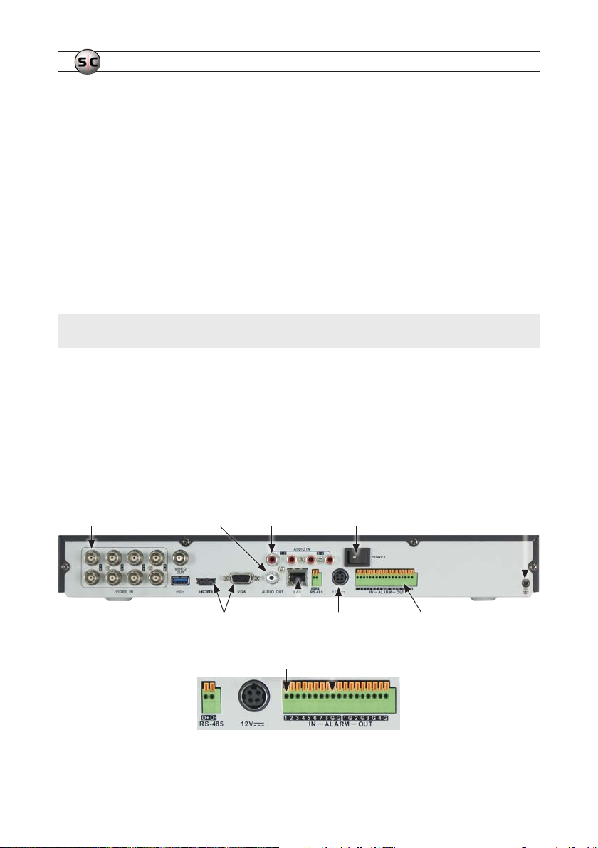
2. Become familiar with t he back panel of the ALI-QVR4008H recorder. The connection points for the devices included in this
interview room system are shown in the images below.
VIDEO IN CH 1
for camera
AUDIO OUT
to speakers
HDMI/ VGA
to monitor
AUDIO IN CH 1 input
from microphone
12 VDC Plug for
LAN
power adapter
ALARM IN 1 GROUND (G)
Power
switch
Ground
terminal
Alarm Terminations
(See image below)
10
www.Observint.com
SECTION 3: SYSTEM SETUP
3. Connect a ground c able to the ground terminal on the back of t he recorder. Follow local electrical codes to ensure the
recorder is properly grounded.
4. Plug the mouse provide d into the USB port on either the f ront or back of the recorder.
5. Position the monitor in an appropriate viewing location and connect it to the recorder using either the VGA or HDMI interface.
A VGA cable is provided with the 23LGLED2 monitor, but the HDMI interface provides the be st performance.
6. NOTE: Do not power on the recorder or monitor at this time. The power switch on t he recorder is located on the back panel
near the 12V power adapter input.
7. If the recorder will be accessible across a local LAN, connect it to a L AN at this time.
NOTE
Do not power on the recorder or moni tor at this time. The power switch on the recorder is located o n the back panel near the
power plug.
3.2 Mount and wire the AVSI switch
The AVSI switch is used to s tart and stop recorder. Find the best location to locate the switch. NOTE: A 100 f t CAB-SWITCH cable
provided is use d to connect the switch to the re corder.
1. Route the CAB -SWITCH cable between the re corder and the location where the AVSI switch will be mounted.
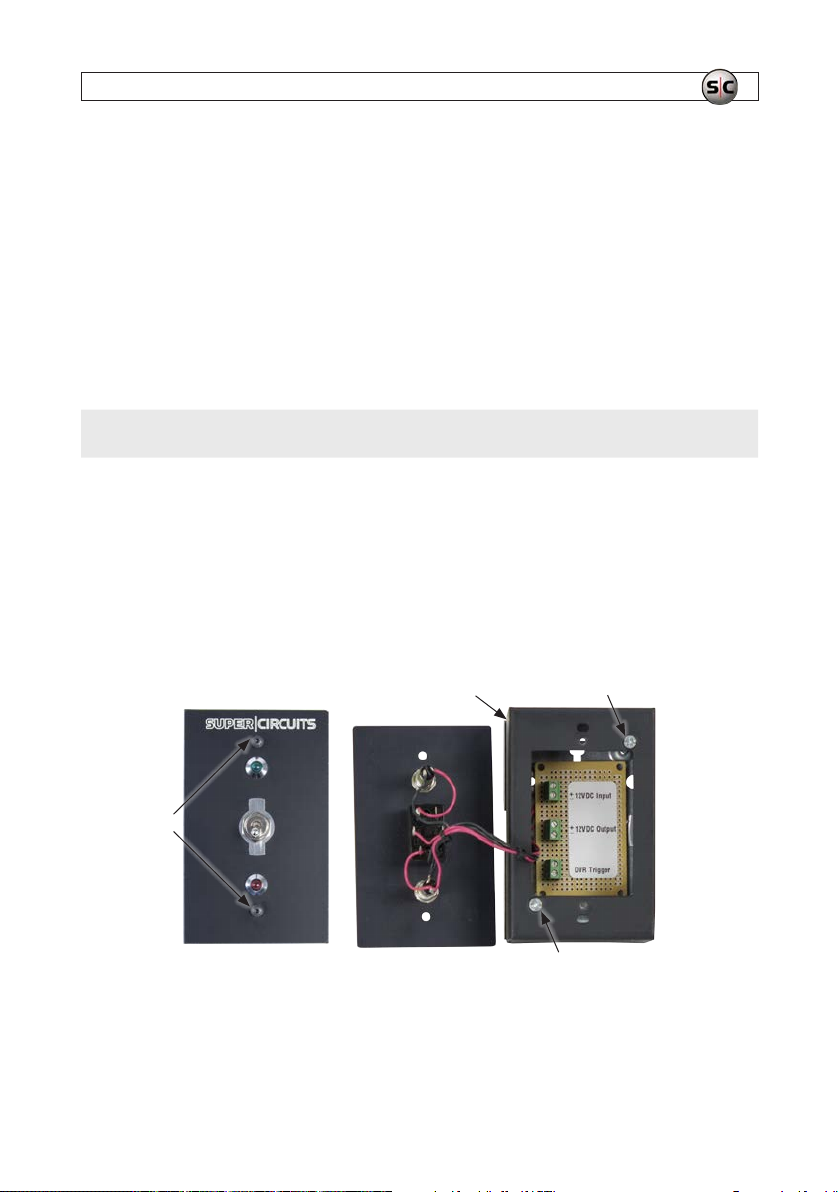
2. Carefully remove the cover screws of the AVSI switch wi th a 5/64” hex wrench, then set the cover aside.
Box Screw
Cover
screws
Screw
3. Remove the two screws securing the box to the bac king plate (see above) using a Phillips screwdriver, then set it aside.
11AVSI-12 Interview Room System Setup and User Guide

SECTION 3: SYSTEM SETUP
Knockouts
Knockouts
4. Remove a knockout from the box or back ing plate for cable routing (see above).
5. Anchor the backing plate to the AVSI switch mounting location with appropriate f asteners (not provided). Several screw
holes are provide d in the backing plate. Use at least two fastener s.
6. Connect the CAB -SWITCH cable to the switch as follow s:
a. Route the CAB-SWITCH cable f rom the mounting location to the recorder back panel.
b. Remove about 2” of insulating sheath from the end of the cable.
Insulating sheath
removed here
CAB-SWITCH
cable
c. Unravel the red -black pair from the green-white pair, then strip 1/4” of insulation from each of the four wire s using a
22 gauge wire stripping tool.
d. Using a 1/8” wide blade screwdriver, loosen the f our screw-down terminals on the backing plate board for the 12V DC
Input and DVR Trigger.
e. Insert wires into the four terminal one at a time as follows. For each, screw in the terminal screw until the wire cannot
be pulled out easily.
12
www.Observint.com

SECTION 3: SYSTEM SETUP
i. Secure the red wire into the 12VDC Input “+” terminal.
ii. Secure the black wire into the 12VDC Input “–” terminal.
iii. Secure the white wire into either terminal of the DVR Trigger.
iv. Secure the green wire into the other terminal of the DVR Trigger.
7. Re-attach the box to the b acking plate with the cables rou ted through the knockout and the 12VDC Output cable connector
contained within the box. Use the t wo Phillips screws removed earlier. See the photo below.
Arrange the cables within the box so they are packed along the lef t side as shown above, then reattach the AVSI switch cover
using the two hex screws removed earlier.
3.3 Connect the CAB-SWITCH cable to the recorder alarm ter-
minals and to 12 Vdc power
At the back panel of the recorder, do the following:
1. Remove about 2” of insulating sheath from the end of the CAB -SWITCH cable.
2. Unravel the red and black pair f rom the green and white pair, then strip 1/4” of insulation from each of the four wires using a
22 gauge wire stripping tool.
13AVSI-12 Interview Room System Setup and User Guide

SECTION 3: SYSTEM SETUP
3. At the alar m terminations, push and hold in the orange button associated wi th the ALARM IN 1 terminal, insert the
CAB-SWITCH cable green wire all the way in, and then release the orange button. Tug on the wire to ensure that is securely
attached.
ALARM IN (1)
Back of recorder
Ground (G)
To AVSI switch
CAB-SWITCH cable
4. Push and hold in the orange button ass ociated with one if the G (ground) terminals, insert the CAB-SWITCH cable white
wire all the way in, and then release the orange bu tton. Tug on the wire to ensure that is securely attache d.
5. Connect the C AB-SWITCH cable red and black wires to a FEMALE-POW power cable screw-down terminals, pairing the
red wire to the red w ire of the power cable, and the black wire to the black wire of the power c able. See the photo below.
14
14
www.Observint.com
 Loading...