

Page 1
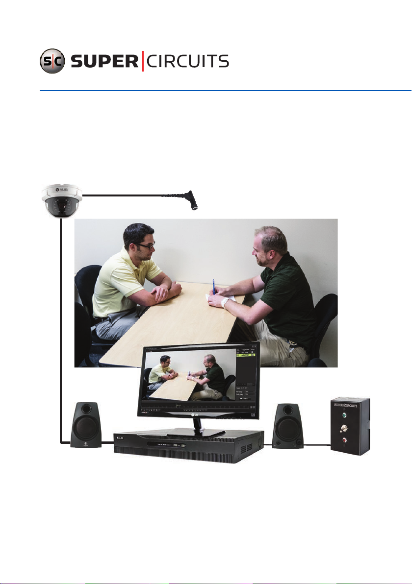
AVSI-11 Interview Room System
Setup and User Guide
PLEASE READ THIS MANUAL BEFORE USING YOUR SYSTEM, and always follow the
instructions for safety and proper use. Save this manual for future reference.
AVSI-11_SM
170613
Page 2
CAUTION
LEGAL NOTICE
Operate this system onl y in environments where the temperature and h umidity is within the recommend ed range. Operation in
temperatures or at hum idity levels outside the recommen ded range may cause electric shock and sh orten the life of the produc t.
Refer to the specicati ons for each system component fo r more information.
Supercircuits
products are designed to meet safety and performance standards with the use of specic
Supercurcuits authorized accessories. Supercircuits disclaims liability associated with the use of non-Supercircuit s
authorized accessories.
The recording, transmission, or broadcast of any person’s voice without their consent or a court order is strictly
prohibited by law.
Supercircuits makes no representations concerning the legality of cer tain product applications such as the making,
transmission, or recording of video and/or audio signals of others without their knowledge and/or consent. We
encourage you to check and comply with all applicable local, state, and federal laws and regulations before
engaging in any form of sur veillance or any transmission of radio frequencies.
Alibi and the Alibi logo are trademarks of Observint Technologies.
Microsoft, Windows, and Internet Explorer are either registered trademarks or trademark s of Microsoft Corporation in
the United States and/or other countries. Android is a trademark of Google Inc. Use of this trademark is subject to
Google Permissions. Apple, iPhone, iPod to uch, and iPad are registered trademarks of Apple Inc.
Other trademarks and trade names may be used in this document to refer to either the entities claiming the marks
and names or their products.
than its own.
No part of this document may be repro duced or distributed in any form or by any means without the express written
permission of
Supercircuits.
Supercircuits disclaims any proprietary interest in trademarks and trade names other
© 2017 by Supercircuits. All Rights Reserved.
11000 N. Mopac Expressway, Building 300, Austin, TX 78759
For Sales and Support, contact your distributor.
ii
www.Supercircuits.com
Page 3

Table of Contents
SECTION 1 Systems Overview ...................................................................1
1.1 System components ..................................................................2
1.2 Recommended options ...............................................................7
1.3 Camera options ......................................................................7
SECTION 2 Getting Started: Unpacking Your System ...............................................9
2.1 Unpacking the equipment .............................................................9
2.2 What you need ......................................................................9
SECTION 3 System Setup ......................................................................10
3.1 Install the recorder hardware .........................................................10
3.2 Mount and wire the AVSI switch .......................................................11
3.3 Connect the 4-wire cable to the recorder alarm terminals and to 12 Vdc power ...............13
3.3.1 Test the AVSI switch .............................................................15
3.4 Install the camera and microphone ....................................................16
3.5 Powering on the system for the rst time ..............................................18
SECTION 4 Test/Use the Interview Room System ................................................. 31
4.1 Playback recorded video .............................................................32
4.2 Tagging recorded video ..............................................................36
4.2.1 Search for and Playback a Tag ....................................................37
4.3 Export recorded video ...............................................................39
4.3.1 Export video during playback .....................................................39
4.3.2 Using the Export menu to locate and export video les ...............................43
4.4 Manual recording ...................................................................50
SECTION 5 Advanced Recorder Features ......................................................... 51
5.1 User Management ..................................................................51
5.2 Network Setup .....................................................................52
5.3 Remote Access ......................................................................52
5.4 System Maintenance ................................................................53
APPENDIX A Conguration Setup for Interview Room System ........................................54
iiiAVSI-11 Interview Room System Setup and User Guide
Page 4

NOTES
iv
www.Supercircuits.com
Page 5
SECTION 1: SYSTEM OVERVIEW
SECTION 1
Systems Overview
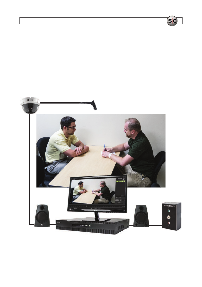
The AVSI-11 Interview Room system is a premium quality scalable video and audio digital recording system ideally sui ted for indoor
installation in rooms where interviews or interrogations occur. Recording c an be started and stopped with one s witch, or manually
at the recorder. The digit al recording system allows you to search and playback live video and audio, and expor t recordings locally or
download them remotely. Additionally, you can expand the system to moni tor and record up to 4 interview rooms simultaneously.
The recorder can b e networked on a LAN and congured for remote access, providing live view, playback, download and manual
recording capabilities from a Microsof t® Windows® computer.
Dome camera Microphone
Interview room
Speakers
Monitor
Video recorder
Record control switch
AVSI-11 System Components
1AVSI-11 Interview Room Switch Systems Setup Guide
Page 6
SECTION 1: SYSTEM OVERVIEW
1.1 System components
The interview room system components include:
Quantity Description
1 23” 1080 p Full-HD Wide screen Commerc ial Grade LED Mo nitor
1 Alibi 16- Channel 1080p/ 960H HD-TVI/Anal og/IP Hybri d+ Real-Time Secu rity digit al video record er
1 Alibi Vanda l proof Outdoo r Dome Secur ity Camera
1 Mono aud io 3.5mm female to RC A male adapter
1 Powered stereo speaker set
1 Power adapter cable
1 Wall swit ch for star ting and stopin g recording (even t recording).
1 100’ 4 -conducto r 22 ga. bulk cable (gre en, white, red, b lack)
1 Female RCA to female RCA adapter
1 12 Vdc 1A regulated p ower adapter
1 12 Vdc 2A regula ted power adapte r
1 65 ft Vi deo/Audio/Power ex tension cab le
1 Female power lead
1 1TB SATA Hard Drive
1 Super high gain micro audio system microphone
1 Single female to dual male power adapter
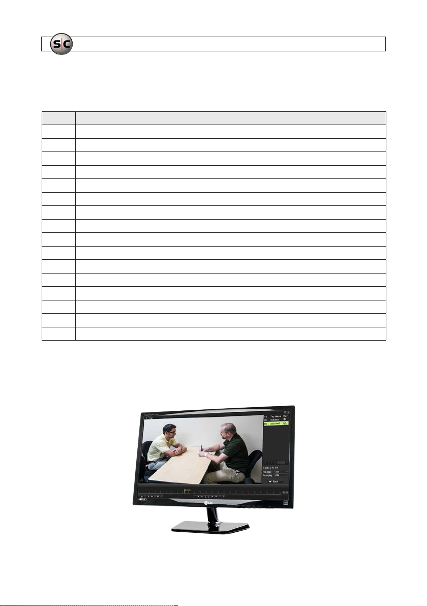
23" Monitor
This 23 inch (23 in diagonal) LED monitor deliver s 1920 x 1080 (1080p) full-HD video resolution and f eatures a non-glare 16:9
aspect ratio and wide viewing angle.
2
www.Supercircuits.com
Page 7
SECTION 1: SYSTEM OVERVIEW
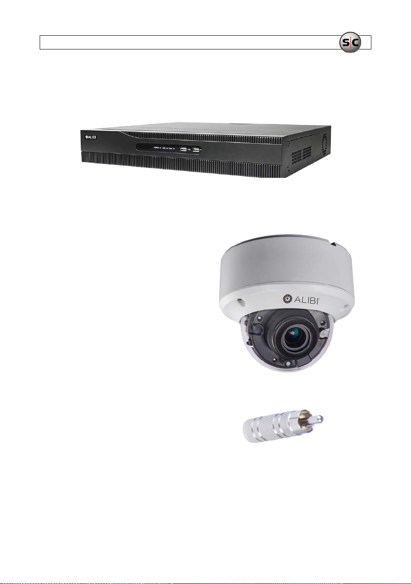
Alibi 16-channel recorder
The Alibi 16-channel hybrid+ digital video recorder supports 1080p HD-TVI, analog and IP cameras. The 1TB hard disk drive (see
below) is pre-installed. It can be cont ain up to four HDDs, each with a capacity of 4TB for a max imum system capacity of 16TB.
Dome Camera
The Alibi Vandal proof IR Outdoor Dome Security Camera
includes a 2.0MP High-Perfor mance CMOS that deliver sharp,
detailed 1080p resolution HD video.
One of the advantages of this varif ocal camera is the
motorized zoom lens that allows you to remotely cont rol
zoom. Innovative Full Frame Illumination technolo gy
with Smart Long-Range IR enable s this camera to reduce
overexposure of the IR LEDs at the center of the image,
increase illumination up to 30%, produce LED light in
rectangle form to bet ter t screen size, and capture image s in
the dark without washing out the subject at closer ranges.
Audio Adapter
Converts 3.5 mm plug to RCA male.
3AVSI-11 Interview Room System Setup and User Guide
Page 8
SECTION 1: SYSTEM OVERVIEW
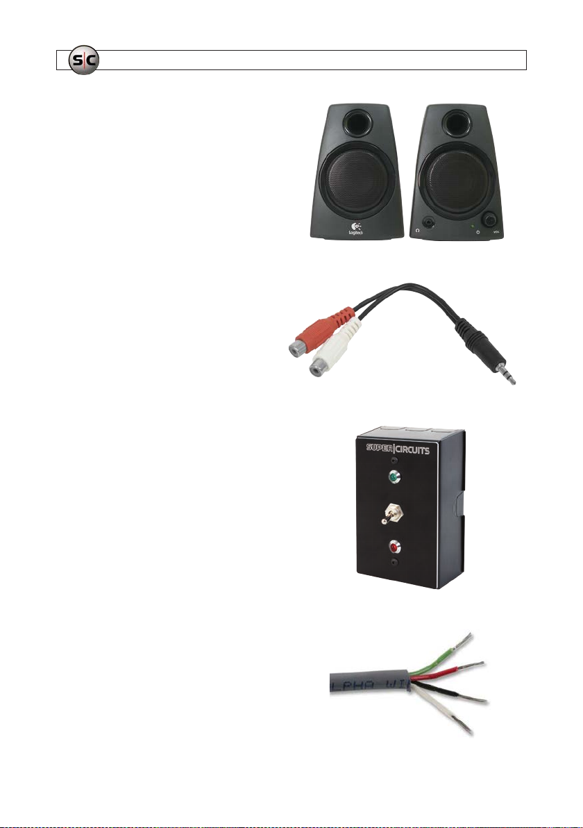
PC Speaker s
The PC speakers is a high quality computer compatible powered
stereo speaker se t. It connects to the audio ou t jack on the back
of the recorder.
Stereo adapter cable
RCA audio lef t and right to 3.5 mm stereo connec tor adapter
cable.
Recording control switch
The switch is a simple ush-mountable interview room switch
assembly that is us ed to start and stop recording equipment with
a single toggle of the switch. The switch is designed to t into a
1-gang electrical box. All terminations to the switch are on the
inside on the back of t he box.
4-wire cable
100 ft 4-wire shielded 22 gauge cable for 12 Vdc power and
switch inter-device wiring.
4
www.Supercircuits.com
Page 9
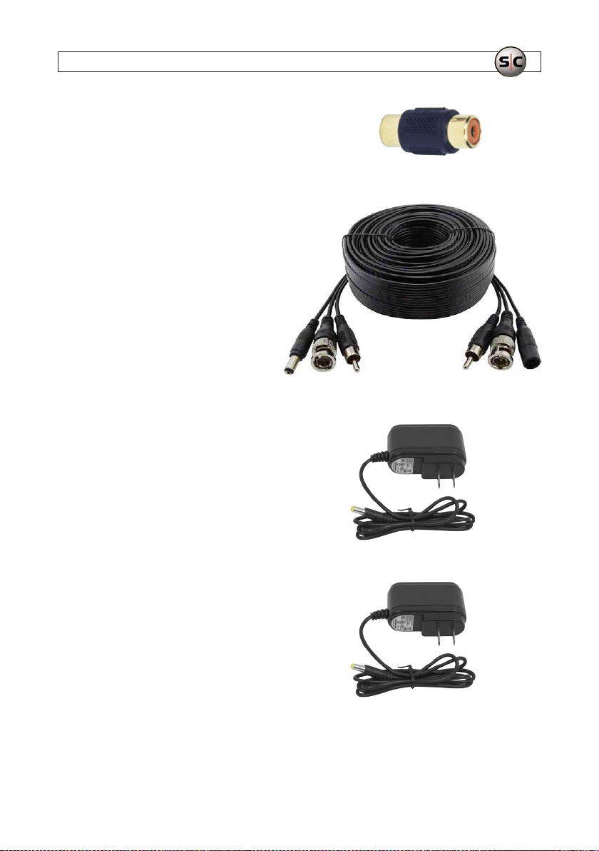
RCA adapter
This is a female RCA to f emale RCA adapter audio.
65 ft Video/Audio/Power extension cable
This extension cable features:
• 65 ft Video, Audio & Power Cable
• HD-TVI, HD-SDI, AHD, HD-CVI, 960H and HD AVS
• BNC Video Connection, RCA Audio Connection
• 2.1 x 5.5mm Power Connector (Standard)
12 Vdc 1 Amp power adapter
A 12 Vdc 1 amp (1000 mA) re gulated power supply is used for
powering the recording control switch.
SECTION 1: SYSTEM OVERVIEW
12 Vdc 2 Amp power adapter
The 12 Vdc 2 amp (2000 mA) regulated power supply is used
to power the dome camera.
5AVSI-11 Interview Room System Setup and User Guide
Page 10
SECTION 1: SYSTEM OVERVIEW
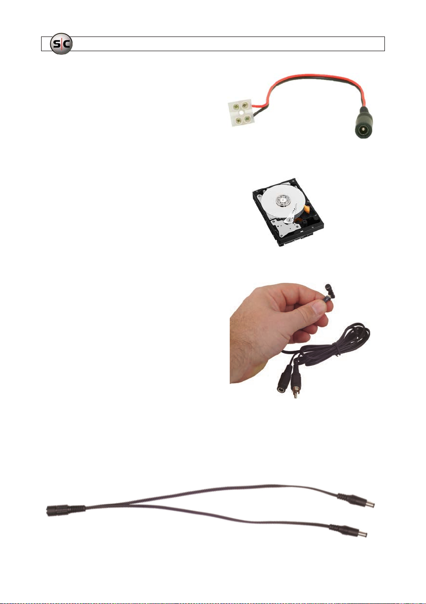
Female power cable adapter
EZ-Connect power cable with plug f or use with the
DC12-1000R power adapter.
1TB Hard Disk Dri ve (HDD)
This professional grade, 1TB hard drive is designed for
the continuous re cording ne eds of security applic ations,
delivering the ultimate in performance and reliabilit y. It
is pre-inst alled and pre-congured in the re corder. The
QVR is upgradable to 16TB of storage with four HDDs.
PA3 Super high gain micro audio system microphone
The PA3 high gain super mini preamp and microphone is one of
the smallest and best in the world. The built-in preamp features
low noise, high gain and auto level adjustment by on -board IC,
and line level output. This microphone comes with a six f oot
microphone lead plug and play cable with RC A connections. It
weighs under 1/2 ounce and provide s a line level output.
Single female to dual male power splitter adapter
This power adapter is used to split power on the video/audio/power extension cable to the camera and microphone. Power on the
cable is provided by the power adapter at the recorder end.
6
www.Supercircuits.com
Page 11
SECTION 1: SYSTEM OVERVIEW
1.2 Recommended options
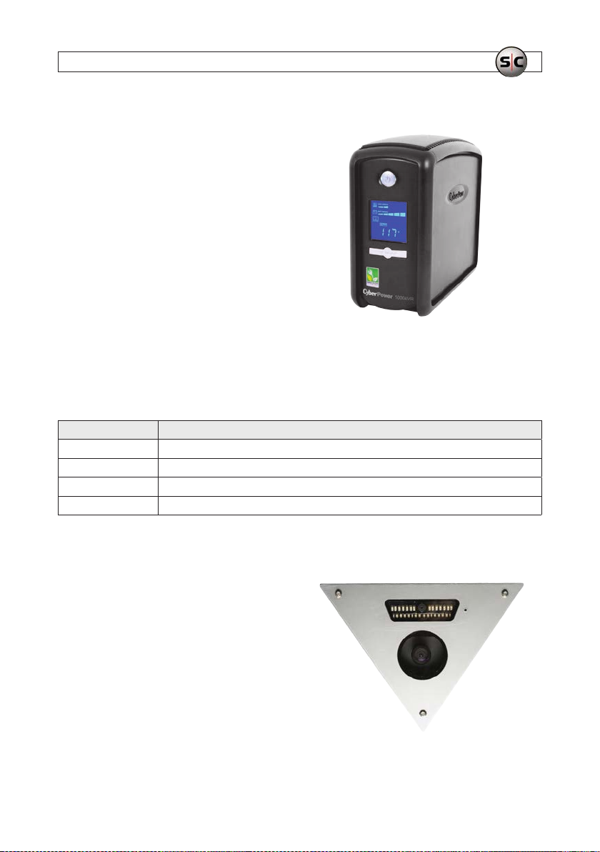
UPS-1000 Uninterruptible power supply (UPS)
The UPS feature s 890 /1080 Joules of surge protection, and
provides bat tery backup during power outages. It includes
automatic voltage regulation for inconsistent utilit y power,
automatically increasing or decreasing input voltage to a
consistent 110 Vac ~ 120 Vac output. Integrated batterie s
provide power when t he incoming voltage drops below 90 Vac
or increases above 140 Vac.
The UPS is used to distribute power to the recorder, monitor,
AVSI switch, camera and audio base station.
1.3 Camera options
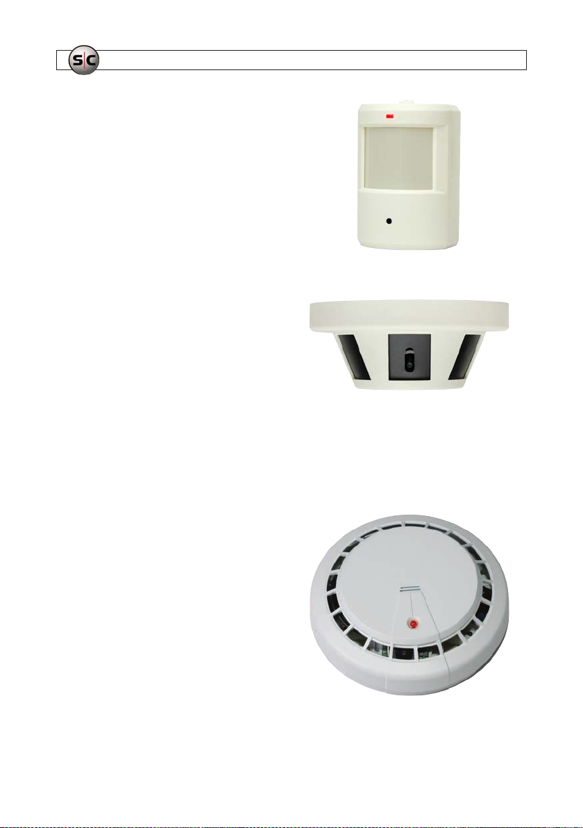
You can upgrade your sys tem to include any of the following cameras:
SKU Description
ALI -CC1 Alibi 2.2 Me gapixel 1080p H D-TVI 40’ IR Wi de Angle Corner M ount Securi ty Camera
ALI- CC2 Alibi 2.2 Megapixe l 1080p HD-TVI 9 40 nm 40’ IR PIR S ensor Color Hid den Camera
ALI- CC3 Alibi 2.2 Megapixe l 1080p HD-TVI 9 40 nm 40’ IR Smo ke Detector H idden Camera
ALI -CC4 Alibi 2 .4 Megapixel 1080 p HD-TVI, AHD, CVBS S moke Detect or Securit y Camera
ALI-CC1
The ALI-CC1 Alibi 2.2 Megapixel 1080p HD-TVI 40’ IR Wide
Angle Corner Mount Security Camera capture s sharp, detailed
full-HD vide o. It is ideal f or monitoring entryways, or anywhere a
commanding view of an entire room is required to be viewed, and
activit y recorded. It includes a 2.9 mm wide angle megapixel lens
to capture a wide view of larger areas.
7AVSI-11 Interview Room Systems Setup Guide
Page 12
SECTION 1: SYSTEM OVERVIEW
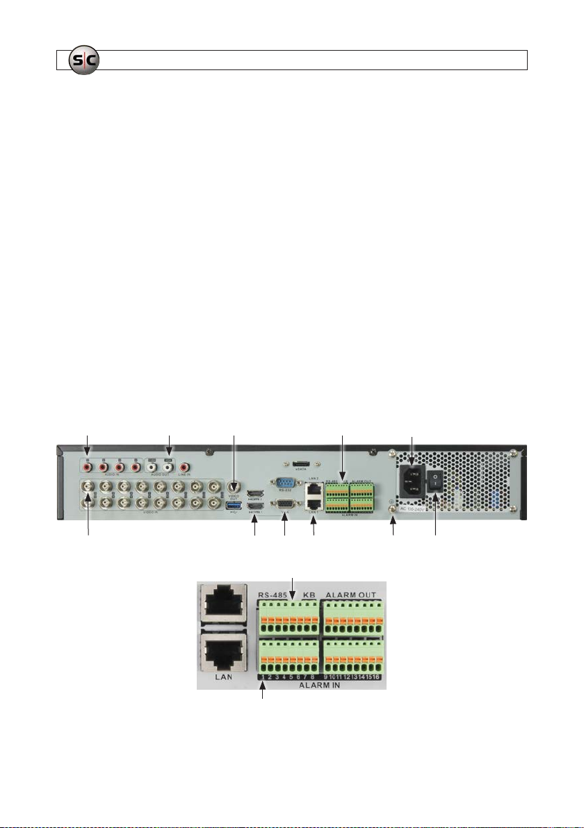
ALI-CC2
Capture high resolution covert video day and night wit h the ALICC2 Alibi 2.2 Megapixel 1080 p HD-TVI 940 nm 40 ft IR PIR Sensor
Hidden Camera. It is ideal for monitoring hallways, entryways,
open areas, or anywhere a commanding view of an entire room is
required to be vie wed, and activity recorded. It feature s a 3.7 mm
wide angle megapixel lens to capture a wide view of larger areas.
The covert camera oers Smar t IR technology that reduces over
exposure of the IR LEDs at the center of the image. An integrated IR
array is virtually undetec table. True day/night (ICR) capt ures sharp,
detailed image s day and night.
ALI-CC3
This 2.2 megapixel hidden camera features a 3.7 mm wide angle
megapixel lens to capture a wide view of larger areas. The covert
securit y camera produces up to 1920 x 1080 (1080p) full-HD
video resolu tion at 30 fps for sharp, detailed images. It is ideal
for monitoring hallways, entry ways, open areas, or anywhere a
commanding view of an entire room is required to be viewed, and
activit y recorded. The camera includes Smart IR technology that
reduces over exposure of the IR LEDs at the center of the image. An
integrated IR array enables the camera to see up to 40 ’ in the dark
without washing out the subjec t at closer range. True day/night
(ICR) captures shar p, detaile d images day and night.
ALI-CC4
This covert smoke de tector camera is equippe d with a 2.4 MP Sony
Progressive Sc an Sensor that delivers clear, crisp 1080p video at
30 fps. Additional features include D-WDR (Digital Wide Dynamic
Range) and 3D- and 2D-DNR (Digital Noise Reduction) that f urther
contribute to it s exceptional quality images, even in low-light
conditions. When used alone, the 4.3 mm wide angle lens in this
camera oers a 90-de gree Field of View, or you can achieve a
full 360- degree view when you add up to 3 addit ional cameras
within the smoke de tector. The adjustable bracket s ystem of the
CC4 allows a total of 4 security cameras (one included, plus 3
additional) to be installed easily, allowing you to covertly monitor
activit y and protect your asset s.
8
www.Supercircuits.com
Page 13

SECTION 2: GETTING STARTED: UNPACKING YOUR SYSTEM
SECTION 2
Getting Started: Unpacking Your System
2.1 Unpacking the equipment
Remove the equipment from its packaging and place it on a at, clean surf ace. Inspect each item. If any visible damage is present,
contact your supplier for a replacement. Verify that your order is complete. Wit hin your order you should nd:
• 1 - 23” monitor with the associated video and power cables
• 1 - Alibi 16-channel Digital Video Recorder (DVR). The DVR will contain the HDD option(s) you ordered.
• 1 - Alibi dome camera
• 1 - Hi-gain omnidirectional microphone
• 1 - Audio adapter - convert s 3.5 mm plug to RCA male plug
• 1 - RCA female to female adapter
• 1 - AVSI speaker kit
• 1 - AVSI switch
• 1 - 65 ft video/audio/power extension cable
• 1 - 100 ft 4-conductor cable
• 1 - 12 Vdc 1 Amp power adapter
• 1 - 12 Vdc 2 Amp power adapter
• 1 - Female power adapter with screw- down terminals
• 1 - Power splitter (Y-adapter)
Refer to the user manual for the product for a list of specic items included with the product. T he user manual may be provided on
the CD included with the produc t.
2.2 What you need
To install the AVSI-SW1 Interview Room Switch, you need:
• 5/64” hex wrench
• #1 Phillips screwdriver
• Small slot screwdriver
• Screws and tools for mounting the wall plate
9AVSI-11 Interview Room System Setup and User Guide
Page 14
SECTION 3: SYSTEM SETUP
SECTION 3
System Setup
The basic Inter view Room System system includes an Alibi HD-TVI digit al video recorder, an HD-TVI 1080p high denition cameras,
an audio microphone an d base unit system, and a Record/Standby switch.
3.1 Install the recorder hardware
Installing the recorder hardware includes an Alibi HD-TVI recorder and a monitor. When inst alling this e quipment, refer to the
recorder quick setup guide (included with the recorder) and other documentation provided with the monitor for more information.
When installing this equipment, using an uninterruptable power supply (UPS) for power backup and ltering is highly recommended.
1. Place the recorder unit in a secure locat ion that is within cable distance to the interview ro om(s) you are monitoring, and in a
location that has restric ted access. When nding a location for the recorder, consider the following:
— Cab le provided between the re corder and the camera is 65 feet. (Longer cables are available.)
— Cab le between the recorder and the switch is 100 fe et.
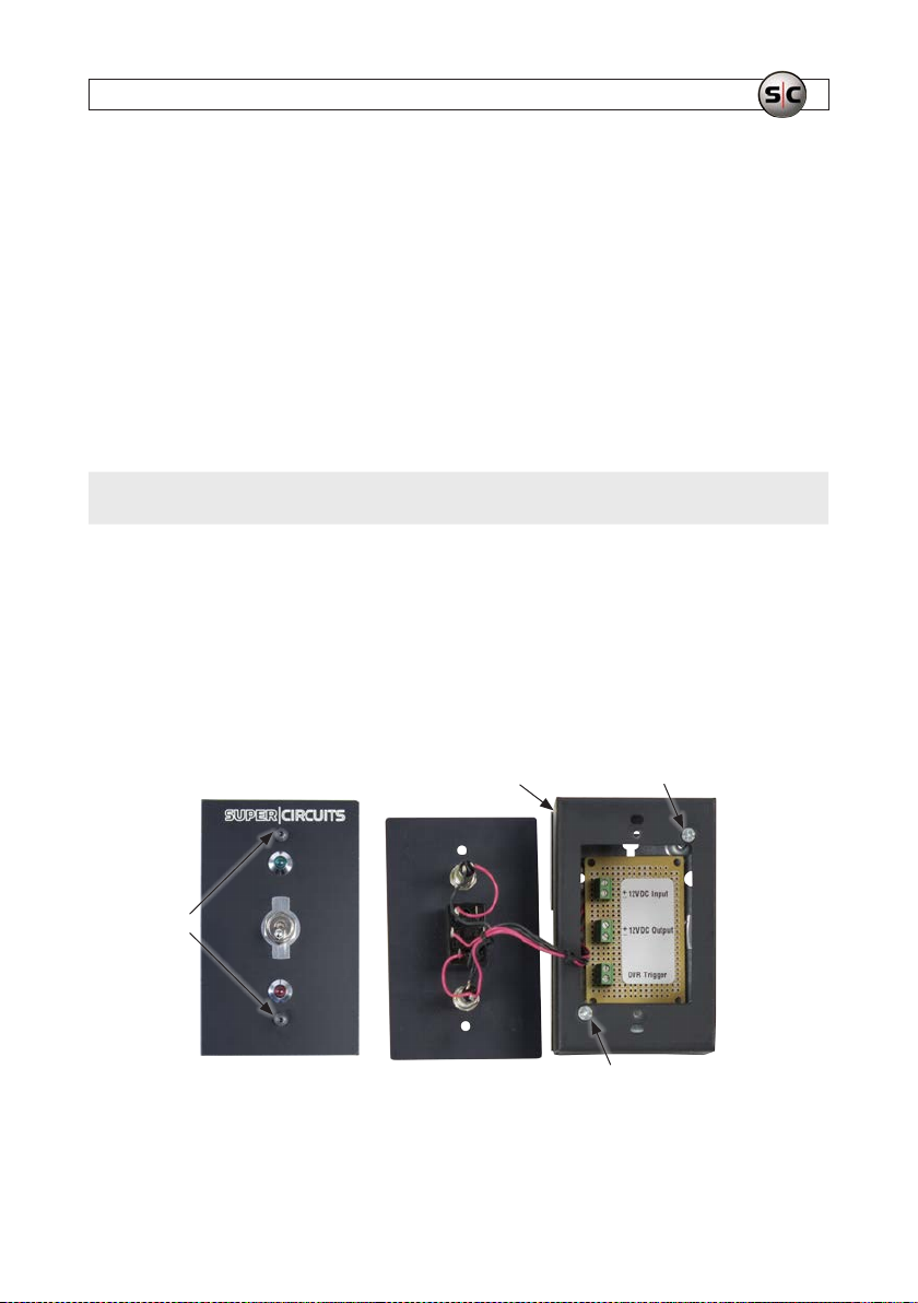
2. Become familiar with the back panel of the recorder. A quick setup guide provided with the unit identies the indicators on
the front panel and connections on the back panel. The connection points for the devices included in this inter view room
system are similar to those shown in the images below.
Camera VIDEO IN 1
10
Audio OutCamera AUDIO IN 1
www.Supercircuits.com
USBUSB
ALARM IN 1
RS-485,Alarms IN/OUT Power connector
LAN (2)
GROUND (G)
Ground
ON / OFF switchMonitor Out - HDMI, VGA
Page 15
SECTION 3: SYSTEM SETUP
3. Connect a ground c able to the ground terminal on the back of the recorder. Follow local electric al codes to ensure the
recorder is properly grounded.
4. Position the monitor in an appropriate viewing location and connect it to the recorder using either the VGA or HDMI cable. A
cable is provided with the monito r. Plug the power cord f or the monitor into a UPS if available, or into a power ou tlet.
5. Plug the power cord provided into the power conne ctor on the back of the recorder and into a UPS, if available, or a power
outlet. NOTE: Do not power on the recorder or monitor at this time. The power switch on t he recorder is located on the back
panel near the ground terminal.
6. If the recorder will be accessible across a local LAN, connect it to a LAN at this time.
7. Plug the mouse provided into the USB port on either the front or back of the recorder.
NOTE
Do not power on the recorder or moni tor at this time. The power switch on the recorder is located o n the back panel near the
power plug.
3.2 Mount and wire the AVSI switch
The AVSI switch is used to s tart and stop recorder. Find the best location to locate the sw itch. NOTE: A 100 ft 4-wire cab le provided
is used to connec t the switch to the recorder.
1. Route the 4-w ire cable between the recorder and the location where the AVSI switch will be mounted.
2. Carefully remove the cover sc rews of the AVSI switch with a 5/64” hex wrench, then set the cover aside.
Box Screw
Cover
screws
Screw
3. Remove the two screws securing the box to the backing plate (see above) using a Phillips screwdriver, then set it aside.
11AVSI-11 Interview Room System Setup and User Guide
Page 16
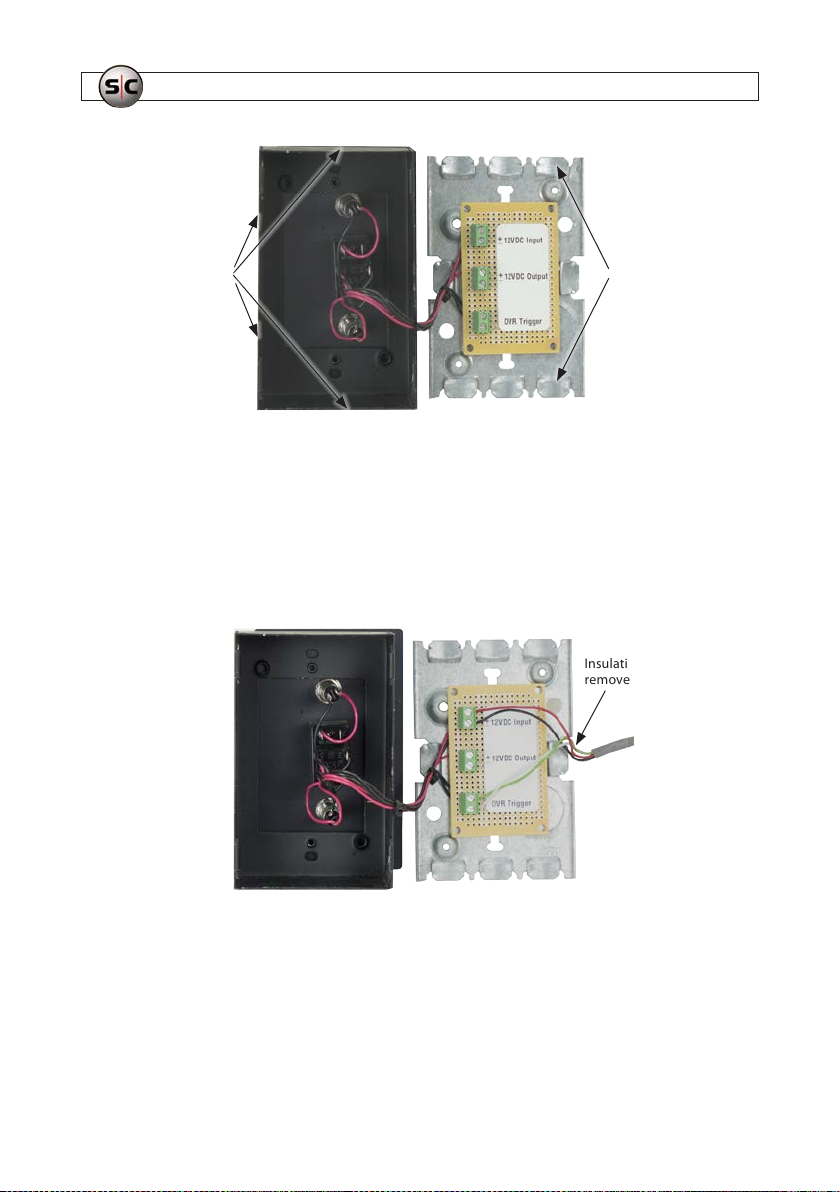
SECTION 3: SYSTEM SETUP
Knockouts
Knockouts
4. Remove a knockout from the box or backing plate for cable rou ting (see above).
5. Anchor the backing plate to the AVSI switch mounting location wit h appropriate fasteners (not provided). Several screw
holes are provide d in the backing plate. Use at least two fasteners.
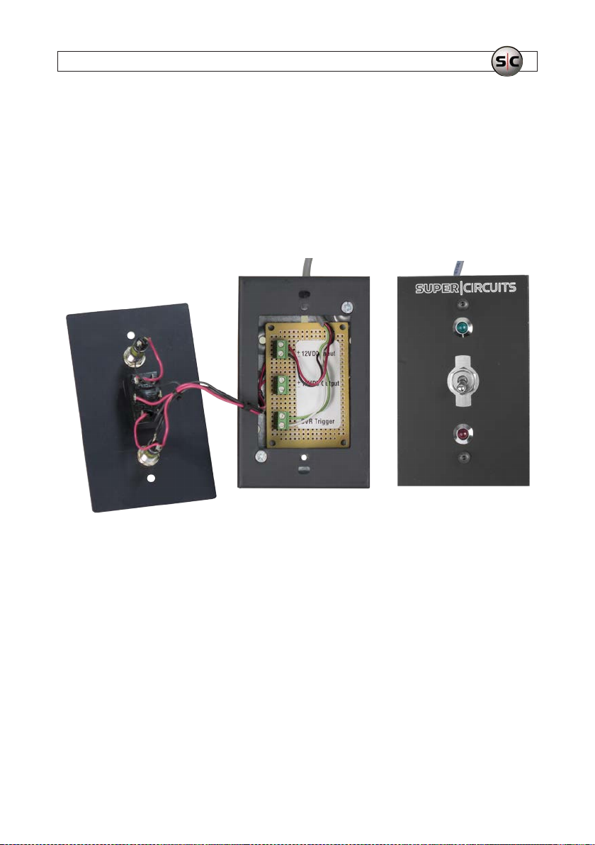
6. Connect the 4-w ire cable to the switch as follows:
a. Route the 4-wire c able from the mounting location to the recorder back panel.
b. Remove about 2” of insulating sheat h from the end of the cable.
Insulating sheath
removed here
CAB-SWITCH
cable
c. Unravel the red -black pair from the green-white pair, then strip 1/4” of insulation from eac h of the four wires using a
22 gauge wire stripping tool.
d. Using a 1/8” wide blade screwdriver, loosen the f our screw-down terminals on the b acking plate board for the 12V DC
Input and DVR Trigger.
e. Insert wires into the four terminal one at a time as follows. F or each, screw in the terminal screw until the wire cannot
be pulled out easily.
12
www.Supercircuits.com
Page 17
SECTION 3: SYSTEM SETUP
i. Secure the red wire into the 12VDC Input “+” terminal.
ii. Secure the black wire into the 12VDC Input “–” terminal.
iii. Secure the white wire into either terminal of the DVR Trigger.
iv. Secure the green wire into the other terminal of the DVR Trigger.
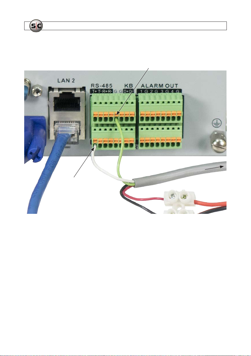
7. Re-attach the box to the b acking plate with the cables rou ted through the knockout and the 12VDC Output cable connector
contained within the box. Use the t wo Phillips screws removed earlier. See the photo below.
Arrange the cables within the box so they are packed along the lef t side as shown above, then reattach the AVSI switch cover
using the two hex screws remove d earlier.
3.3 Connect the 4-wire cable to the recorder alarm terminals
and to 12 Vdc power
At the back panel of the recorder, do the following:
1. Remove about 2” of insulating sheath from t he end of the 4-wire cable.
2. Unravel the red and black pair f rom the green and white pair, then strip 1/4” of insulation from each of the four wires using a
22 gauge wire stripping tool.
13AVSI-11 Interview Room System Setup and User Guide
Page 18
SECTION 3: SYSTEM SETUP
3. At the alar m terminations, push and hold in the orange button associated wit h the ALARM IN 1 terminal, insert the 4-wire
cable white wire all the way in, and then release the orange but ton. Tug on the wire to ensure that is securely attache d.
Ground (G)
Back of recorder
CAB-SWITCH cable
ALARM IN 1
AVSI swi tch
4. Push and hold in the orange button associated with one if the G (ground) terminals, ins ert the 4-wire cable green wire all
the way in, and then release the orange but ton. Tug on the wire to ensure that is sec urely attached.
5. Connect the 4 -wire cable red and black wires to a female power cable adapter screw- down terminals, pairing the red
wire to the red wire of t he power cable, and the black wire to the black w ire of the power cable. See the photo below.
14
www.Supercircuits.com
Page 19
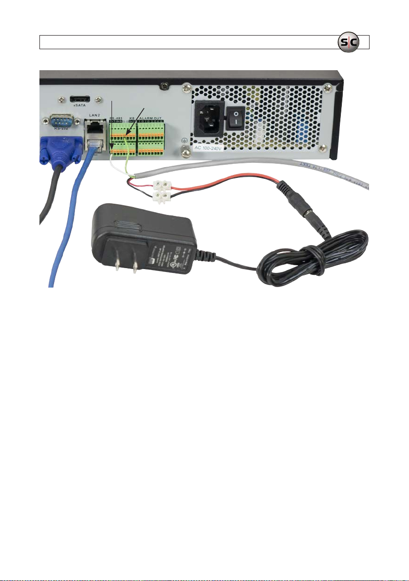
ALARM IN 1 and
ground (G)
SECTION 3: SYSTEM SETUP
Female power
cable adapter
1 A power adapter
4-wir e extension
cable to switch
6. Plug the other end of the Female power cable adapter into a 1 A power adapte r. Do not plug the power adapter into
an electrical outlet at this time.
3.3.1 Test the AVSI switch
1. Plug the 12 Vdc 1 Amp power adapter shown in the photo in step 3 above into a 120 Vac wall outlet.
2. Flip the AVSI switch to the up (record) position. Verify that t he green light is on.
3. Flip t he AVSI switch to the down (standby) posit ion. Verif y that the red light is on.
4. If the verify checks in the two steps above do not produce the expecte d results, check the connec tions to the switch and
power adapter. Contact your vendor suppor t organization of additional help is needed.
5. S et the switch to the down position before performing the following procedures.
6. Place a UPS (Uninterruptible Power Supply, recommended) near the re corder, and then connect power cables from the
recorder and monitor to it. Plug the UPS into a s tandard, grounded electrical outlet . NOTE: Do not power on the recorder or
monitor at this time. The power switch on the recorder is loc ated on the back panel near the power plug.
7. If the recorder will be accessible across a local LAN, connect it to a L AN drop cable at this time.
15AVSI-11 Interview Room System Setup and User Guide
Page 20
SECTION 3: SYSTEM SETUP
3.4 Install the camera and microphone
When performing the follow ing instructions, ref er to the Alibi HD-TVI Dome Camera Quick Installation Guide provided with
your camera for additional information.
8. Mount the Alibi dome camera in the interview room in accordance with the mounting guideline s provided in the installation
instruc tions. Ensure that the camera lo cation will provide the best eld of view of both the interviewer(s) and those being
interviewe d. Note that the camera module is mounted on an internal gimbal to adjust tilt and direc tion.
a. After mounting the camera, leave the dome cover o. The camera direc tion and tilt will be adjusted af ter the recorder
is powered on.
9. Install the microphone to achieve optimal recording of the subject being interviewe d and all other room occupants, be away
extraneous noise, such as from HVAC vents, fans and sounds outside the room, and in a location where it cannot be easily
tampered with. Do not install the microphone on the table where occupants can reach it. Both the camer a drop cables and
the microphone drop cables must be able to connec t to the same video/audio/power extension c able.
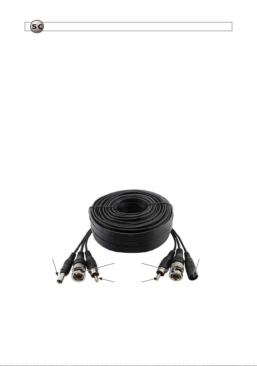
10. Route the video/audio/power extension cable from the recorder to the camera and microphone. Notice that the power
connector s are dierent at the ends of the cable (se e photo below). Ensure that the power connec tor on the recorder end will
mate with the conne ctor on the 12 Vdc 2 Amp power adapter, and the power connector at the camera and microphone end
will connect to the power splitter.
Power connec tor
for camera end
Video
connectors
Audio
connectors
Power connec tor
for recorder end
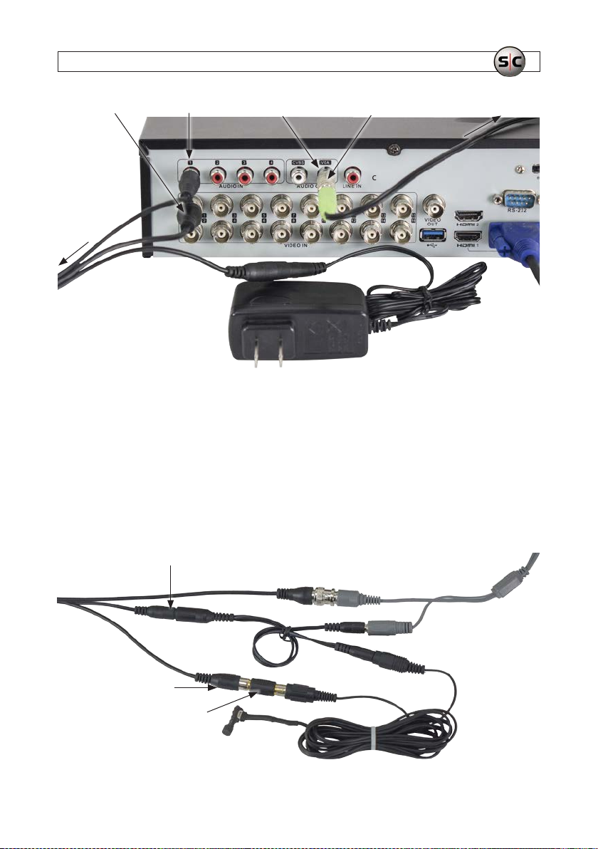
11. Connect the video/audio extension cables to the recorder as follow s:
a. Connect the video/audio/power extension cable with the BNC connector (video) to the VIDEO IN 1 connec tor. See
below.
16
www.Supercircuits.com
Page 21
SECTION 3: SYSTEM SETUP
To camera
and mic
Video/audio/power
extension cable
(recorder end)
AUDIO IN 1 (RCA)VIDEO IN 1 (BNC)
VIDEO IN 1 (BNC)
12 Vdc 2 Amp
power adapter
AUDIO OUT to speakers
Audio adapter
Speaker
cable
To spe aker s
b. Connec t the extension cable with the RCA connector (audio) to the AUDIO IN 1 connec tor (see above).
c. Connect the extension cable power conne ctor to the 12 Vdc 2 Amp power adapter. NOTE: Do not plug the power
adapter into a power outlet at this time.
d. Connec t the Audio adapter to the AUDIO OUT VGA connector, and then plug the speakers c able into the adapter.
12. Connec t the extension cable to the c amera and microphone as follows:
a. Connect the ex tension cable with the BNC connector (video) to the camera drop cable wi th the BNC connector. See
below.
Video/audio/power
extension cable
(camera end)
Audio connector
(RCA)
RCA F to F adapter
Power connector
Video connector (BNC)
Power
splitter
Microphone
Camera video (BNC)
Audio (RCA)
Camera drop cables
Power
Power
17AVSI-11 Interview Room System Setup and User Guide
Page 22

SECTION 3: SYSTEM SETUP
b. Connec t the extension cable with the RCA connector to the RC A female to female adapter. Connect the other end of
the RCA adapter to the microphone drop c able with the RCA connector.
c. Connect the extension cable with the power connector to the power split ter.
d. Connec t one leg of the power splitter to the camera power drop cable. Connect the other leg of the power splitter to
the microphone p ower drop cable.
3.5 Powering on the system for the rst time
Powering on the system for the r st time includes steps to per form the initial recorder conguration and verify sys tem functionality.
When performing this procedure, refer to the following document s provided with the equipment for more information:
Alibi Recorde r Quick Setup Guide
ALIBI™ Embedded Video Recorder Firmware V3.4.80 User Manual (or n ewer)
Alibi Dome Camera Quick Installation Guide
During the initial startup of the recorder, the congur ation Wizard is executed. This Wizard provide s windows for performing the
initial conguration of your system, including changing the administrator password (highly recommended), setting the network
parameters, adding IP cameras to the system and other options. Use the instruc tions below to customize your system for your
location.
Importa nt note about changing yo ur Admin password
NOTE
After chang ing the administrator password of th e system, an option is available to save a GUID le. This le ca n be used to reset
the Admin passwo rd of the system if you forget your password, a nd should be saved on a USB ash media drive and sto red in a
secure location.
1. Plug the two power adapter at the back of the recorder into a UPS or power outlet.
2. Plug the monitor into a UPS or power outlet, and then power it on the monitor.
a. Check the congurat ion of the monitor to verify that it is using the inter face you chose to connect to the recorder.
3. Plug t he power adapter for the speakers into a UPS or p ower outlet.
4. Power on the recorder using the switch on the back panel near the power cord. Verify that within 2 minutes, the ALIBI splash
screen (see below) is displayed on the monito r.
18
www.Supercircuits.com
Page 23
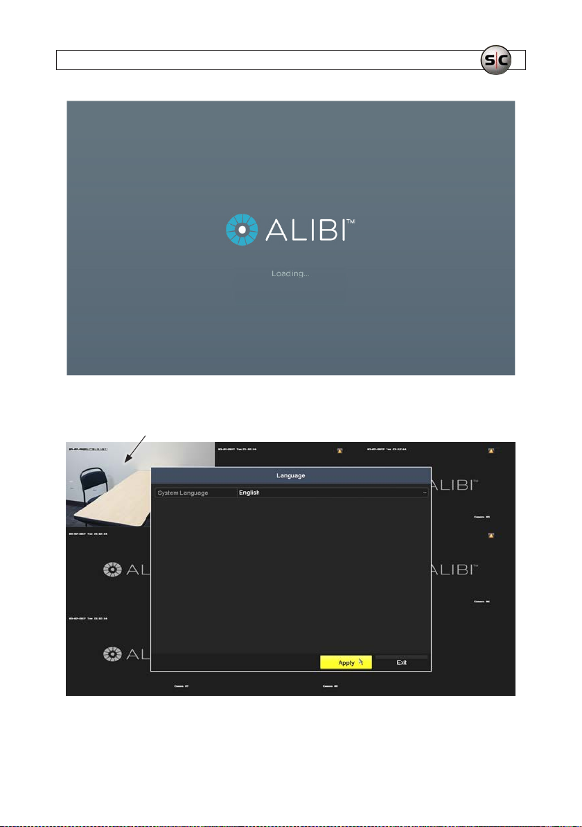
5. In t he Language screen shown below, click Apply to cont inue.
Video image from camera
SECTION 3: SYSTEM SETUP
19AVSI-11 Interview Room System Setup and User Guide
Page 24
SECTION 3: SYSTEM SETUP
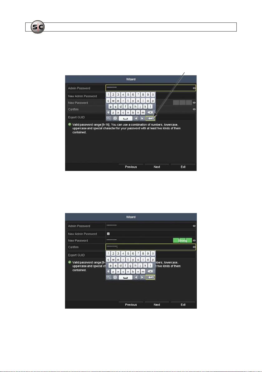
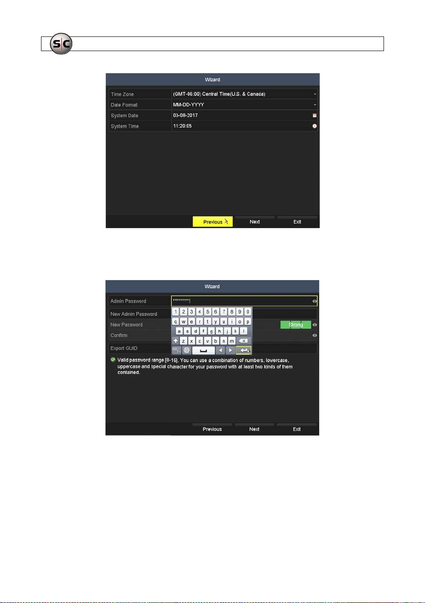
6. In the r st Wizard window, click in the Admin Password entry eld, and t hen use the virtual keyboard to enter the default
administrator password for the system: password1. Click the Retur n key in the lower right corner of the keyboard to
complete the entr y.
Return key
7. After entering the default password, click the New Admin Password box to check it.
8. Enter a new password in the New Password and Conrm Password elds following the recommendation included on
the screen. Choose a password that is rated as a Strong password.
9. Click Next to cont inue.
20
www.Supercircuits.com
Page 25

SECTION 3: SYSTEM SETUP
10. In the Attention window, verify that the password is mo died (see below), and then click OK to continue. If a dierent
message appears, correc t whatever is needed, and then click Next as shown above, and OK to continue.
11. In the next Wizard window, click Previous to retur n to the password screen.
21AVSI-11 Interview Room System Setup and User Guide
Page 26
SECTION 3: SYSTEM SETUP
12. In the password screen shown below:
a. Enter your new Admin password in the Admin Password eld.
b. Unche ck the New Admin Password selec t box.
c. Insert a ash media drive into an open USB port on the recorder.
d. Click on the Expor t GUID eld shown below.
22
www.Supercircuits.com
Page 27
SECTION 3: SYSTEM SETUP
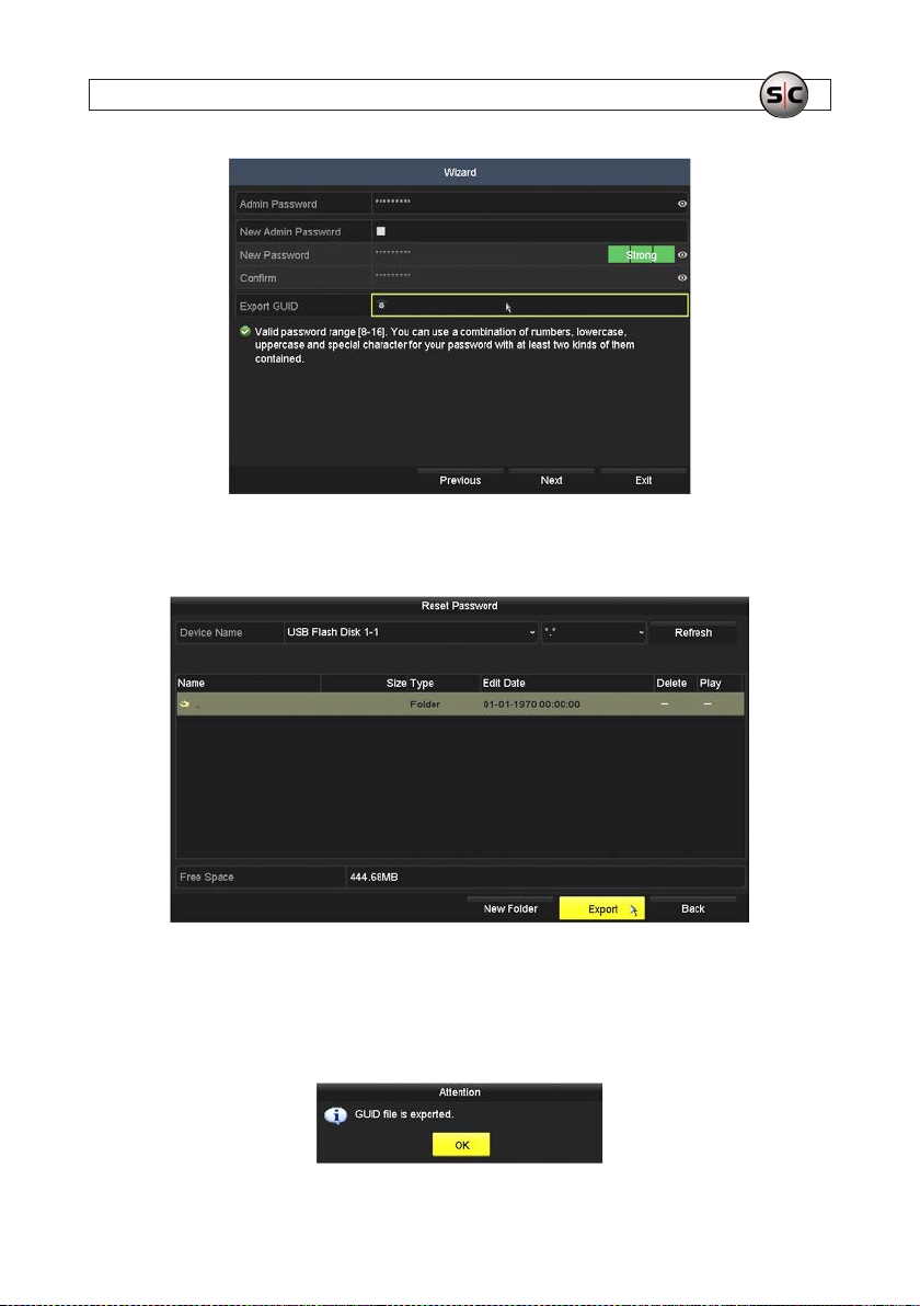
13. The Reset Password window will reco gnize your USB drive and show the le struc ture. If the window doesn’t show the
drive, click the Refresh but ton to scan the USB ports for the drive.
14. In the screen above, you can:
a. Create a new folder on the dr ive, if needed, or double click on an existing folder to open/selec t it.
b. Click the Export button to write the GUID le to the folder that is open. If the export was successful, the Attention
window shown below will appear.
23AVSI-11 Interview Room System Setup and User Guide
Page 28
SECTION 3: SYSTEM SETUP
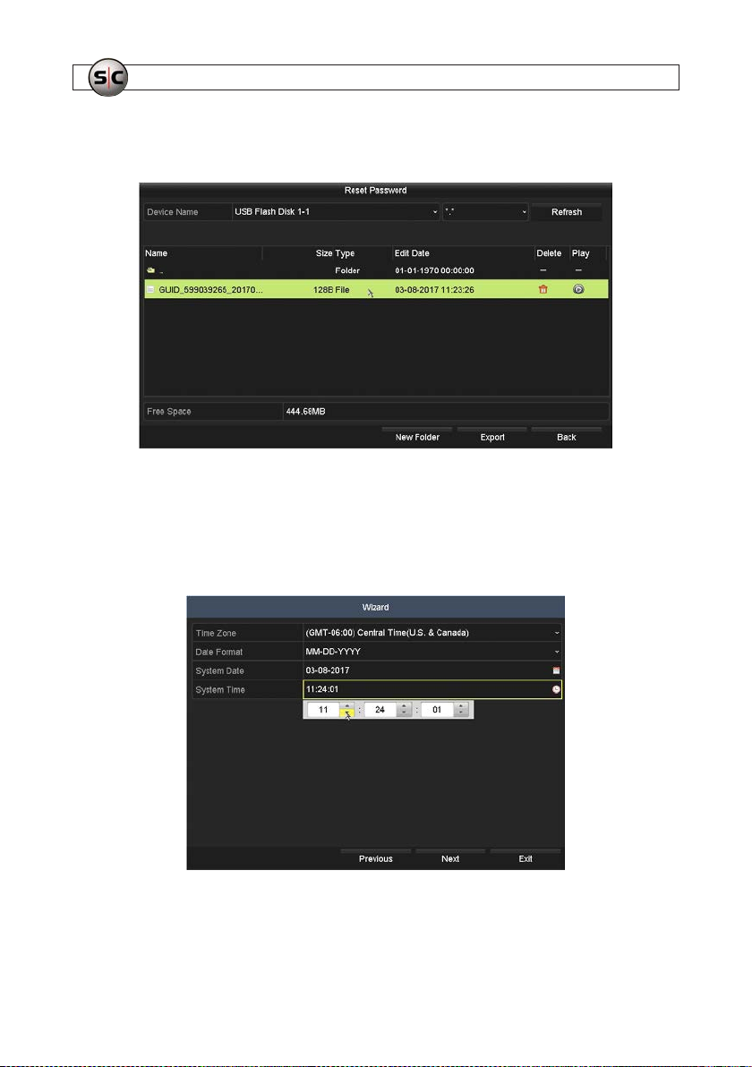
c. Click OK in the At tention window to close it, and then ver ify that the GUID le is now shown in the folder. See the
example below.
d. Click the Back to return to the Wi zard.
e. Remove the USB drive from t he recorder and store it in a secure lo cation.
15. In the Date/Time setup screen:
a. Open the Time Zone drop down list, and then select t he time zone for your location.
b. Open t he Date Format drop down list, and then select the format you prefer.
c. Click the System Date eld, and then selec t the correct date.
24
www.Supercircuits.com
Page 29
SECTION 3: SYSTEM SETUP
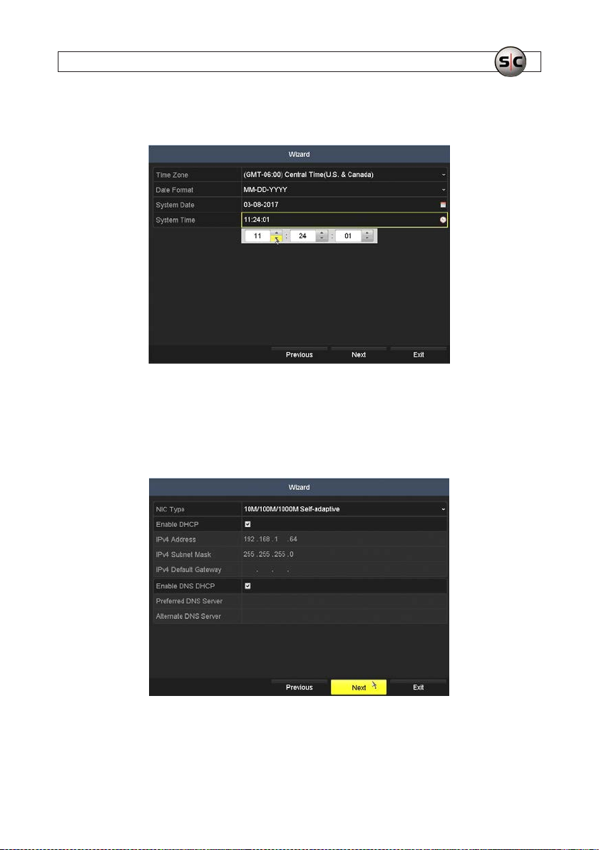
d. Click the System Time eld, and then use the up ( p ) and down ( q ) icons f or each eld to show the current
date. Note that the hour eld is shown in 24-hour (0 .. 23) format .
e. Click Next to continue.
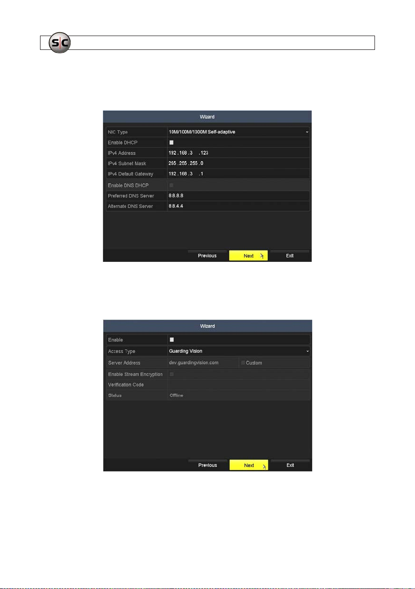
16. The network settings Wizard menu is shown below. By default, t he recorder is congured to use DHCP. If the recorder
is attache d to a LAN that has a DHCP server (most common), this menu will be populated wit h the compatible network
parameters assigned to your by the DHCP. If not, the default set tings are shown in the screen below. In this menu, you can:
— Click Next to continue if your recorder isn’t at tached to a LAN.
— Uncheck the Enable DHCP box and the Enable DNS DHCP box if the net work settings assigne d by DHCP are
acceptable. Unchecking these boxe s assures that the settings are not changed, whic h is preferred if remote logins to
the recorder are us ed. Click Next to continue.
25AVSI-11 Interview Room System Setup and User Guide
Page 30
SECTION 3: SYSTEM SETUP
— Uncheck the Enable DHCP box and/or the Enable DNS DHCP box, and then enter your preferred network settings.
Your settings mus t be compatible with the LAN on which the recorder is at tached (see below). Consult with your
network administrator for suggeste d settings. Click Next to continue.
17. The next Wizard menu is use d to congure cloud services for the information you record. If you are using this feature,
refer the ALIBI™ Embedded Video Recorder Firmware User Manual provided by your equipment vendor for more
information. Click Next to continue.
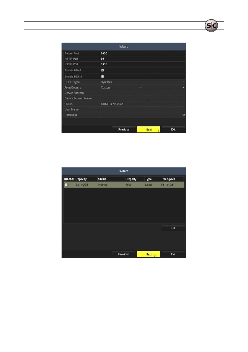
18. The nex t Wizard menu is used to congure the port set tings used by the recorder and for using DDNS ser vices. Refer to the
ALIBI™ Embedded Video Recorder Firmware User Manual provided by your equipment vendor for more information.
Click Next to continue.
26
www.Supercircuits.com
Page 31
SECTION 3: SYSTEM SETUP
19. The nex t Wizard menu is used to initialize (erase all information f rom) the inter nal hard drive (HDD). By default, when the
HDD becomes f ull, it is congured to write over the oldest les on the drive, excluding les that are locked. Click Next to
continue.
20. The next Wizard window is used to add network (IP) cameras to the recorder, neede d. These cameras can be used for
surveillance, or with other interview rooms. Refer to the ALIBI™ Embedded Video Recorder Firmware User Manual
provided by your equipment vendor for more information. Click Next to continue.
27AVSI-11 Interview Room System Setup and User Guide
Page 32
SECTION 3: SYSTEM SETUP
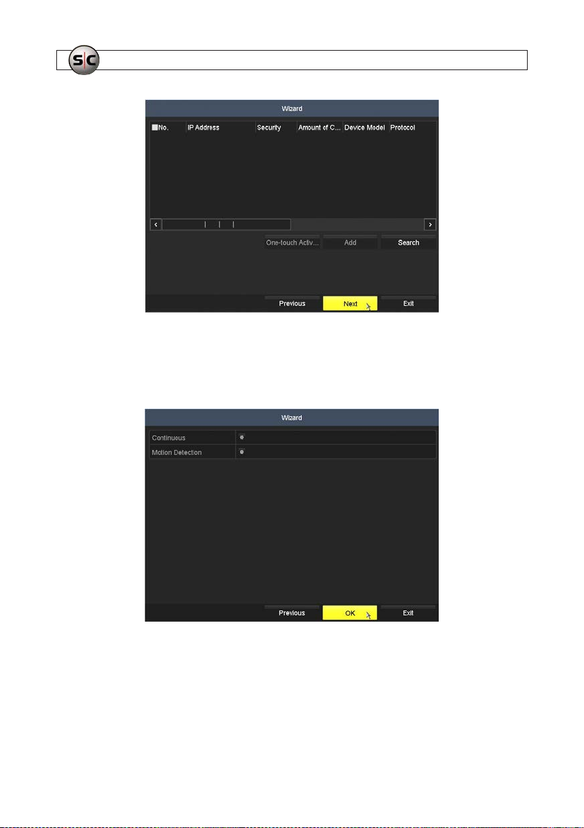
21. The nex t Wizard window is congure the recorder for Continuous or Motion Detec tion recording. Click OK to continue and
exit the Wiz ard. NOTE: Your re corder is precongured to record on Channel 1 when the AVSI switch is on, and
to record on each other channel when motion is detected on that channel. DO NOT SELECT ANY OPTIONS IN
THIS MENU.
22. After exiting the Wizard, the Live View screen will appear.
23. While observing the video image on the L ive View screen, adjust the camer a direction (pan) and tilt to aim at the area you
want to record. Reat tach the dome cover to the camera module.
24. Right click any where on the Live View screen, and then click Menu in the popup lis t. NOTE: An Admin login window may
appear. If it does, enter your Admin password in the window, and then click OK to continue.
28
www.Supercircuits.com
Page 33
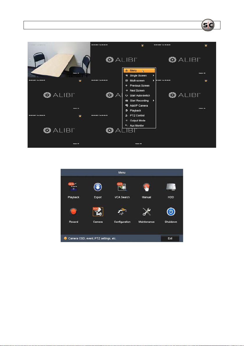
25. In the Menu window, click the Camera icon.
SECTION 3: SYSTEM SETUP
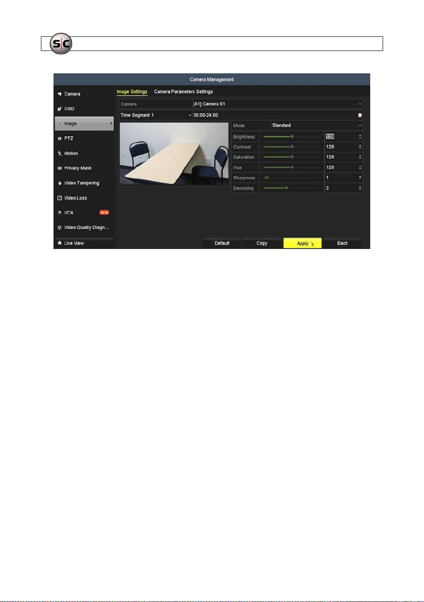
26. In the Camera Management menu, click the Image link on the lef t. By default, image set tings for Camera (A1) Camera
01 (interview room camera) is selec ted. In this menu:
a. Add colorful objects to the interview room, and set the lighting to the normal lighting level. The video in the screen
below is not a good example.
29AVSI-11 Interview Room System Setup and User Guide
Page 34
SECTION 3: SYSTEM SETUP
b. Adjust the brightness, contrast, saturation, hue, sharpness and nois e to perfect the image f rom the A1 camera.
c. Click Apply to s ave your settings, and then click Back to return to the Menu icon window in the Live View screen.
27. Click Exit to close the Menu icon window.
28. Power on the speakers, and then adjust t he speaker volume to adequately hear the sounds in the interview room.
30
www.Supercircuits.com
Page 35
SECTION 4: TEST/USE THE INTERVIEW ROOM SYSTEM
SECTION 4
Test/Use the Interview Room System
Follow the procedures below to test and use the sys tem. Basic system use include s recording video, searching for and playing back
video, and exporting video.
The Interview Room System is precongured to record t he video received on (A1) Camera 01 (Video In 1) and the audio on Audio
In (1) when the AVSI switch is on. When this happens, the Live View display for channel 1 is expanded to full screen.
The recorder feat ures several ways to manage and search for video les, including clipping, tagging, intelligent search, etc. Ref er to
the ALIBI Embedded Video Recorder Firmware User Manual for more information about using the extensive tools and features
of the recorder.
1. In the Live View display, close the Menu window and any other p op-up windows that may be open.
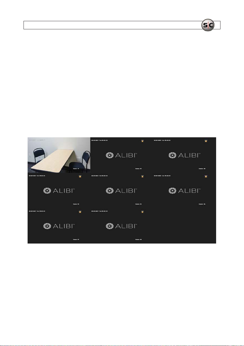
2. Set the Multi-scre en option to anything other than a single channel view (for example, 3 x 3 (see above), 2 x 2, etc.).
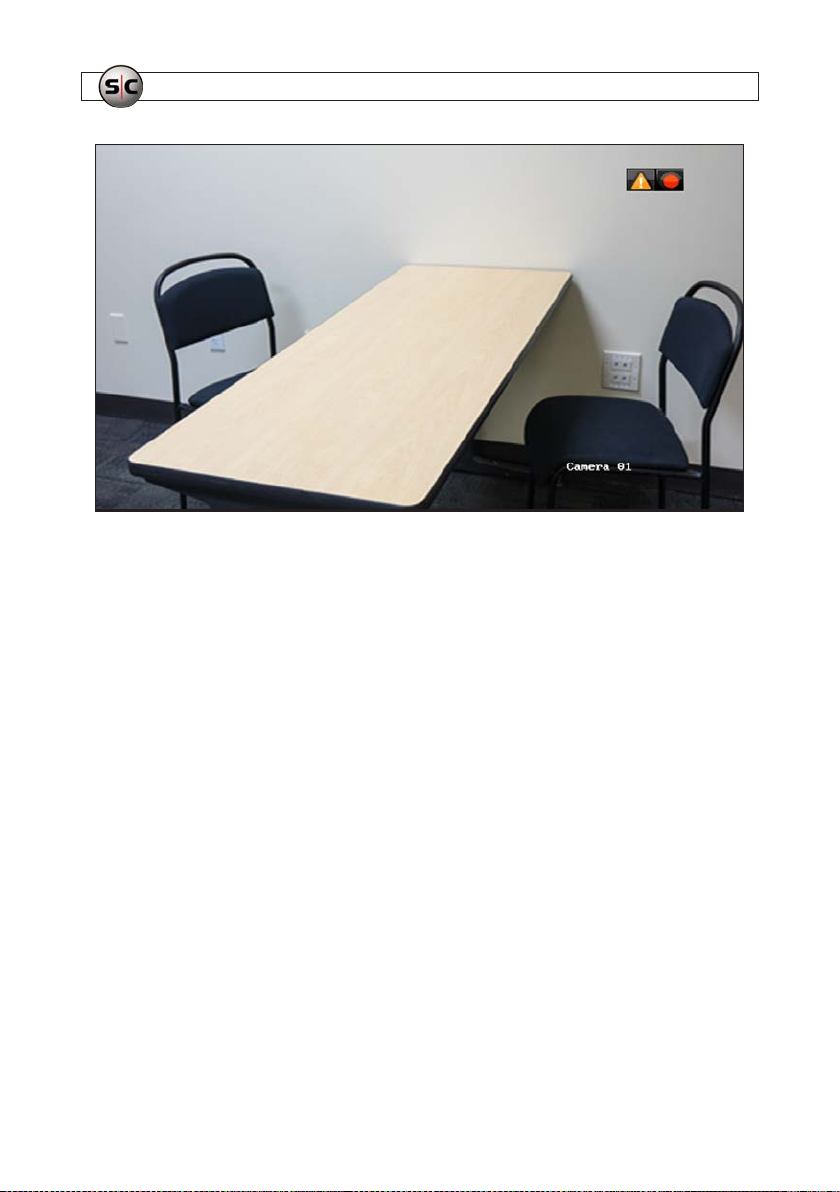
3. Set the AVSI switch to ON. The camera image of Camera 01 should expand to full screen and a red s tatus icon (recording in
progress) should appear in the upper right corner of the screen.
4. Record the time when the AVSI switch was turned on. This information will be used later dur ing playback.
31AVSI-11 Interview Room System Setup and User Guide
Page 36
SECTION 4: TEST/USE THE INTERVIEW ROOM SYSTEM
5. While recording, move throughout the eld of view, and talk normally. Verify that audio can be heard through the speakers.
6. Set the AVSI switch to OFF. The Live View screen should return to Multi -screen mode, and the red status icon in the upper
right corner of Camera 01 video should disappear.
4.1 Playback recorded video
The ALI-QVR4 008H recorder features s everal ways search for, playback and manage video les, including clipping, tagging,
intelligent search, etc. Refer to the ALIBI Embedded Video Recorder Firmware User Manual for more information about using
the extensive tools and features of the recorder.
To playback a recording using the most common method, do the following:
1. Right click anywhere on the Live View screen, and then click Menu in the popup list. NOTE: An Admin login window may
appear. If it does, enter your Admin password in the window, and then click OK to continue.
32
www.Supercircuits.com
Page 37
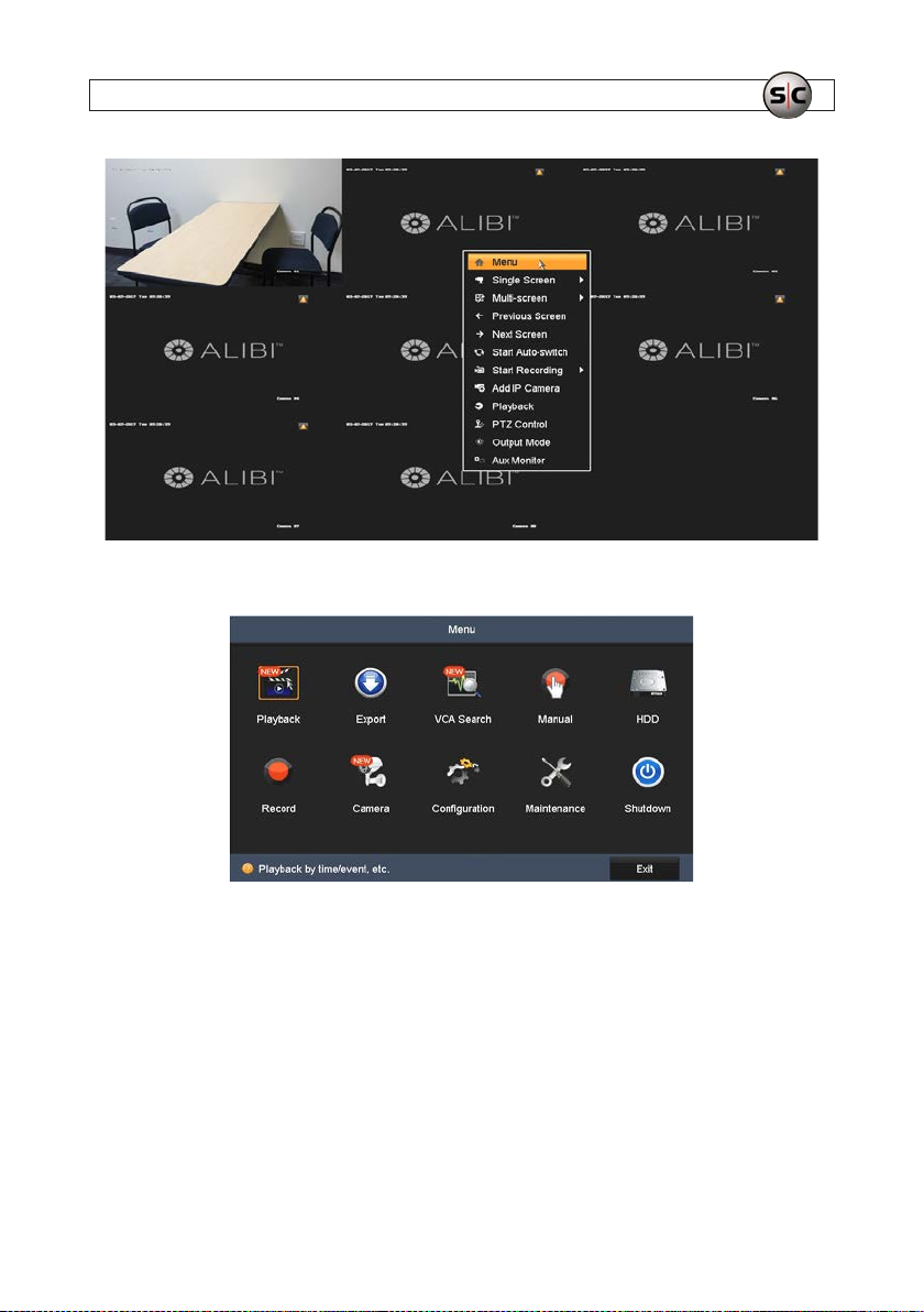
2. In the Menu window, click the Play back icon.
SECTION 4: TEST/USE THE INTERVIEW ROOM SYSTEM
3. In the camera lis t on the right, selec t the Camera 01, the intervie w room camera.
33AVSI-11 Interview Room System Setup and User Guide
Page 38
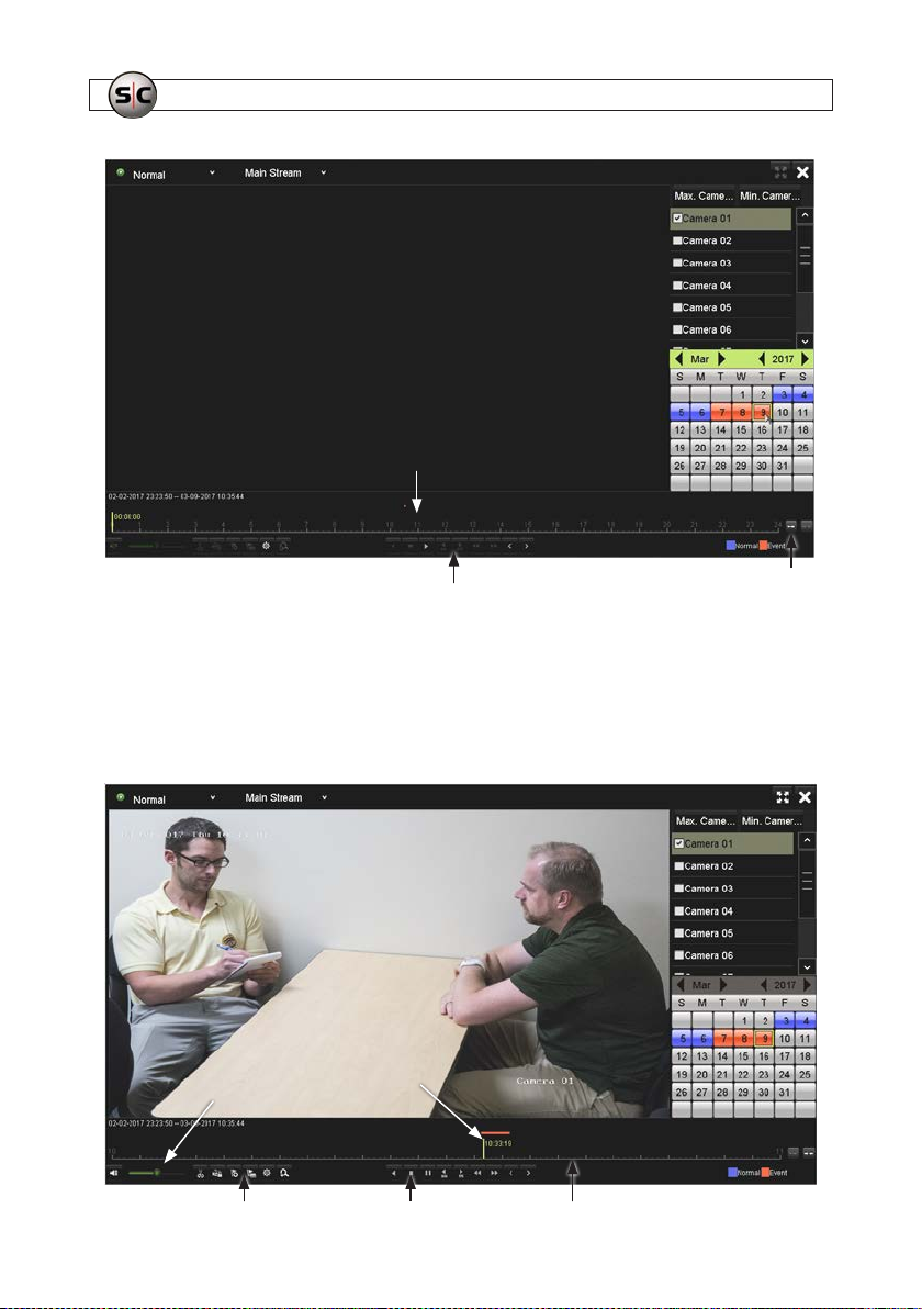
SECTION 4: TEST/USE THE INTERVIEW ROOM SYSTEM
Recording of interest
Playback control icons
Click icons here to expand or
contract the timeline.
4. In the calendar frame, click on the date of the recording you want to playback. In the example above, March 9, 2017 was
selected. After sele cting a date, the timeline at the bot tom of the screen will show times when recordings for the camera
were made, and color-code the mark to indicate if it was a Normal (blue) or Event (red) recording. Recordings initiated by
the AVSI switch will always be Event recordings. Click the icon to the right of the timeline to expand or contract the timeline.
5. Click the Play ( u ) icon in playback controls. The playbac k screen will show the video recorder earlier. You can stop playing
the video by click ing either the Pause ( II ) icon or Stop ( n ) icon.
Timestamp of
Volume control
34
www.Supercircuits.com
video frame shown
Playback con trol icons
E
xpanded timeline Tag, clip, le controls
Page 39
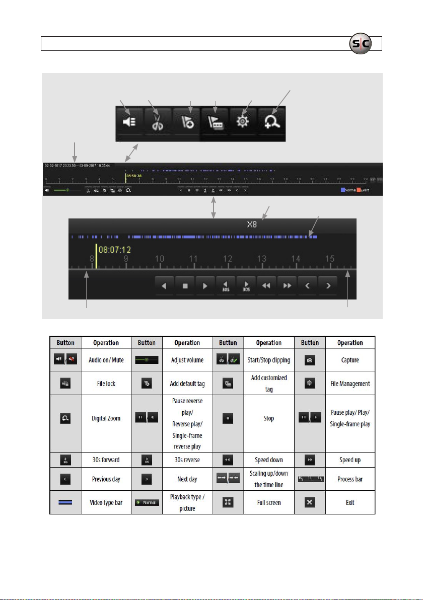
Start/end time
of recordings
Mute
Star t/stop
clip
SECTION 4: TEST/USE THE INTERVIEW ROOM SYSTEM
Add
default
tag
Add
custom
tag
Tag
management
Zoom
Playback timestamp
Playback speed
Recorded video clips
TimelinePlayback motion controls
Playback screen icons
35AVSI-11 Interview Room System Setup and User Guide
Page 40
SECTION 4: TEST/USE THE INTERVIEW ROOM SYSTEM
6. During playback of the video, verify t hat you can hear sound from the recording, and the video s tarted and stopped at t he
time when the AVSI switch was toggled.
4.2 Tagging recorded video
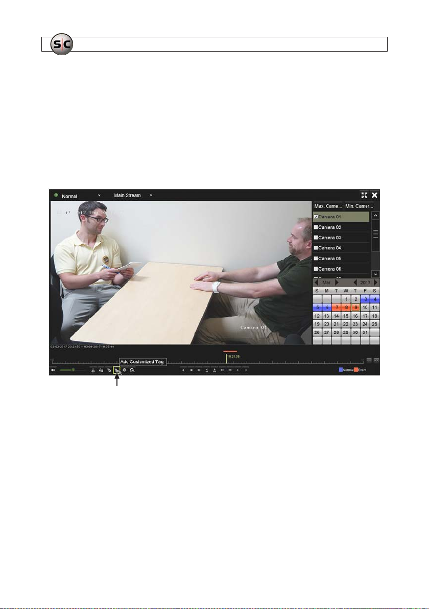
You can tag, or name, video clips during playback, and then easily search for and play them back later. Video clips can also be
“locked” on the HDD to prevent them from being overwritten with newer data. To tag a video:
1. While the video is b eing played back, click the Add Customized Tag icon. See below.
Add Customized Tag icon.
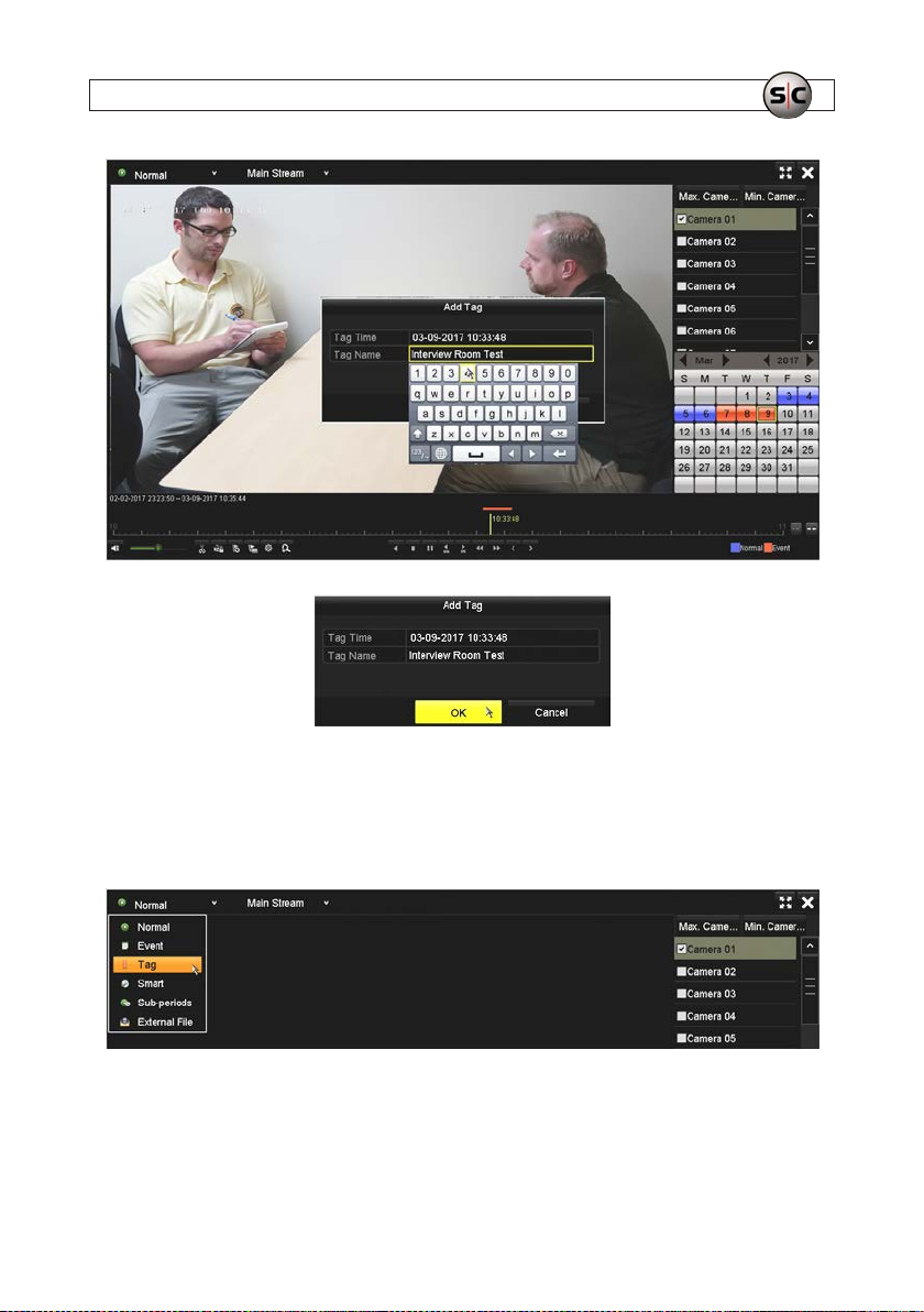
2. In the window that opens, enter a Tag Name, and then click OK to close the window. Notice that the tag is time stampe d at
the time the window opens.
36
www.Supercircuits.com
Page 41
SECTION 4: TEST/USE THE INTERVIEW ROOM SYSTEM
4.2.1 Search for and Playback a Tag
3. Stop video playback in the Playback screen.
4. In the upper lef t corner of the screen, open the drop down list, and then s elect Tag.
5. Check the box to select Camera 01, or select all cameras.
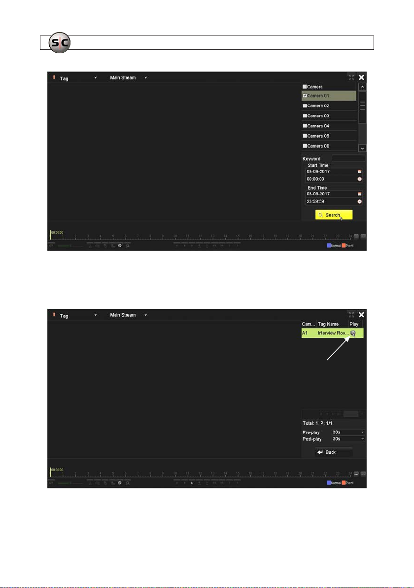
6. In the screen shown below, you can search for a tag by Key word, or specify the Start Time and End Time of the timespan
when the tag was created.
37AVSI-11 Interview Room System Setup and User Guide
Page 42
SECTION 4: TEST/USE THE INTERVIEW ROOM SYSTEM
7. Click the Search button to nd the tag. Tag search results will appear on the right side of the window (see below). Click the
tag vide play icon associated with the tag entry to p lay video. Note that you can adjust the Pre-play and Po st-play times if
needed. To perform another search, click the Back but ton.
Tag video play icon
38
www.Supercircuits.com
Page 43
SECTION 4: TEST/USE THE INTERVIEW ROOM SYSTEM
4.3 Export recorded video
When video is ex ported at the recorder, it is saved, or copied, to a ash media device connecte d to a USB port on the recorder. Two
common ways to export video include:
• Expor ting video clips during playbac k
• Using the Exp ort menu to locate and export video le s
Video can also be played back and exported f rom the recorder through remote access. Refer to the ALIBI Embedded Video
Recorder Firmware User Manual for your recorder for more information about using remote access.
4.3.1 Export video during playback
To export vide o during playback:
1. Plug a USB ash media device into a USB port.
2. Playback the video le that contains the content you want to export.
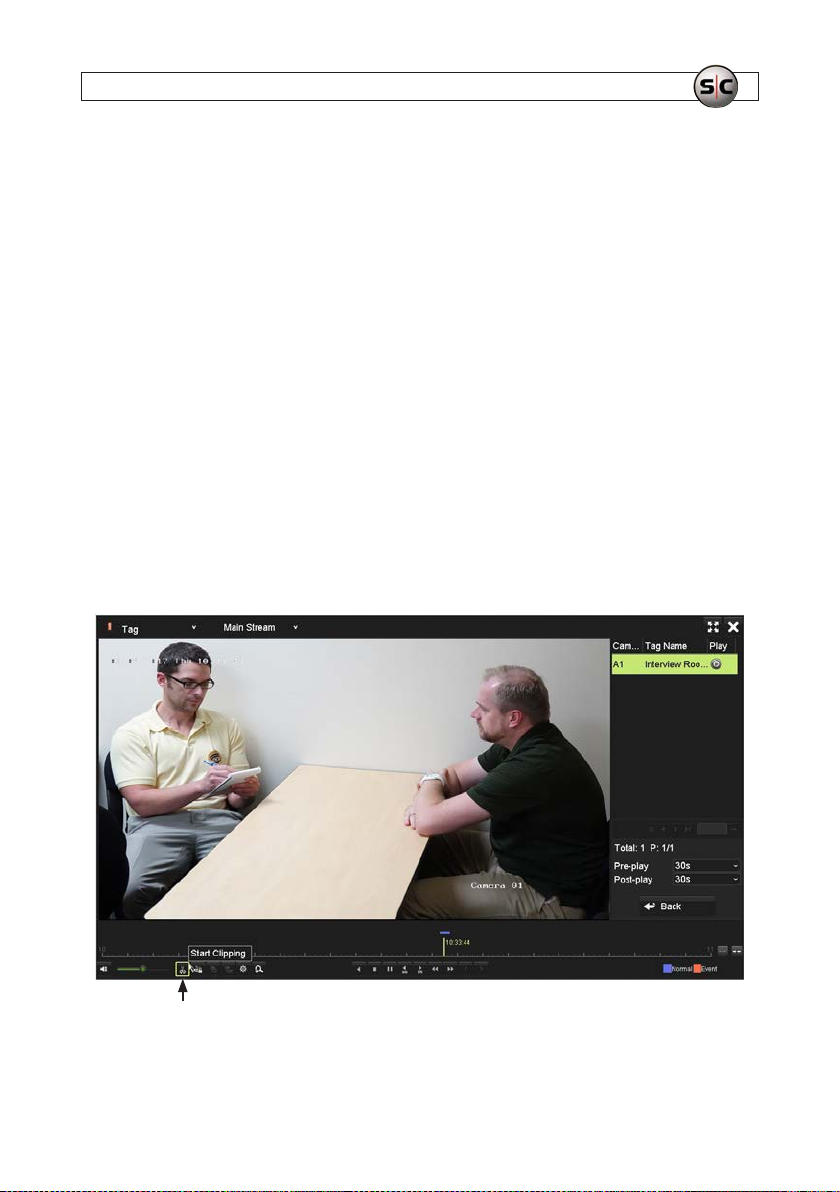
3. Using the playback contro ls, position the video at the frame that begins t he content you want to export.
4. Click the Clip icon at the bot tom of the window. A balloon will appear to signal Start Clipping.
Clip icon.
39AVSI-11 Interview Room System Setup and User Guide
Page 44
SECTION 4: TEST/USE THE INTERVIEW ROOM SYSTEM
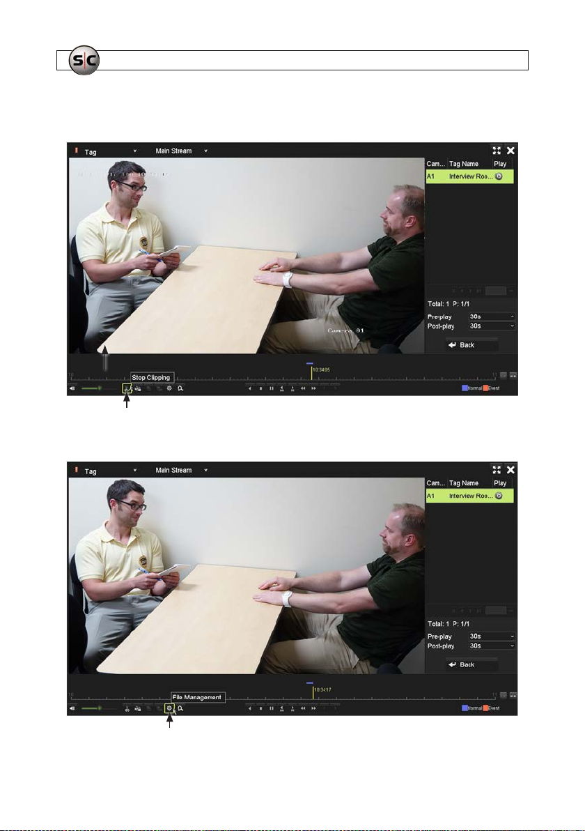
5. Position the vide o at the end of the content you want to expor t, and then click the Clip icon again. This time, a balloon will
appear to signal Stop Clipping.
Clip icon.
6. Click the File Management icon.
FIle Management icon.
40
www.Supercircuits.com
Page 45
SECTION 4: TEST/USE THE INTERVIEW ROOM SYSTEM
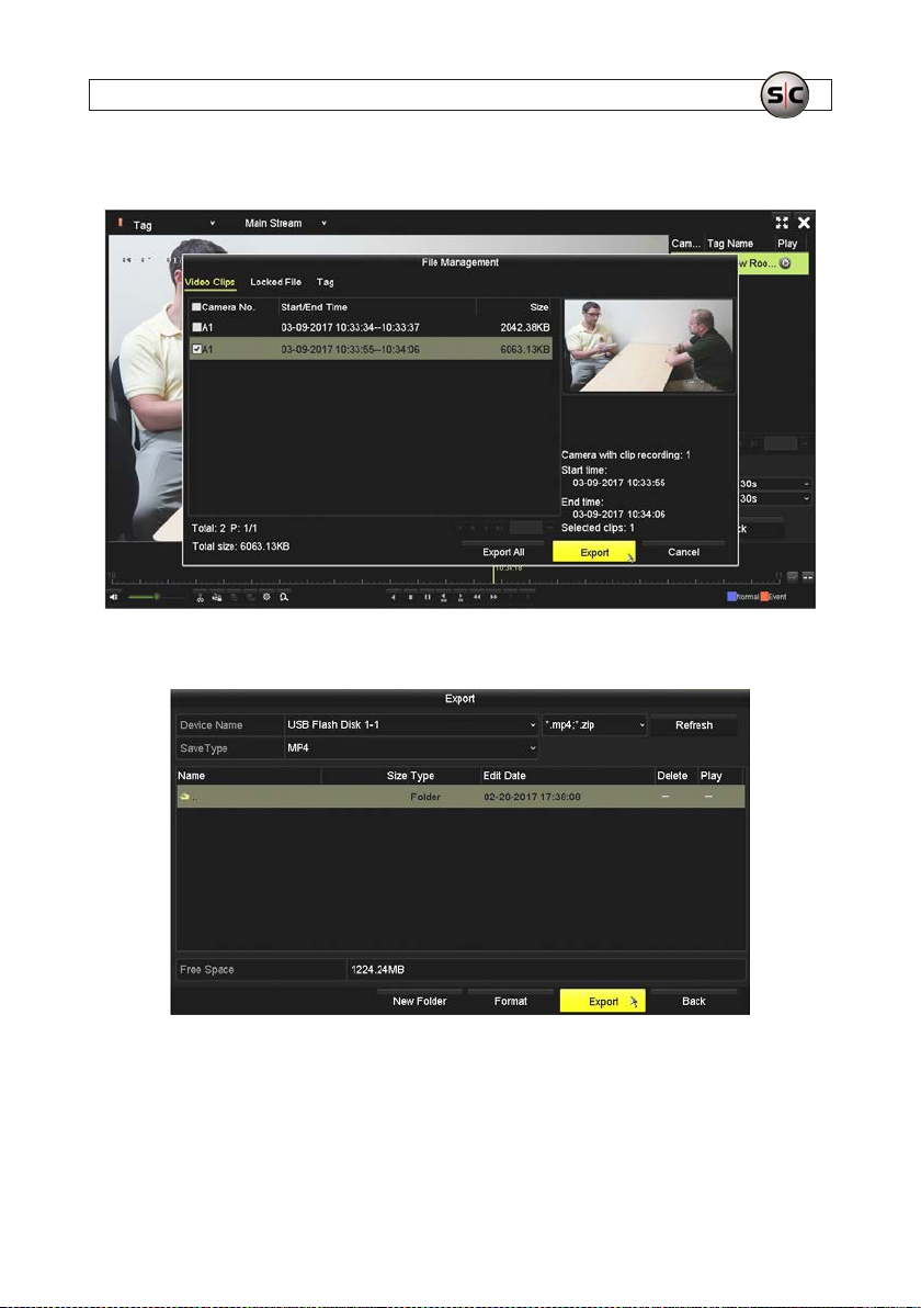
7. In the File Management menu, check the select box for the video clip you want to export, and then c lick Expor t.
8. In the Export window, double click on the folder where you want to expor t the le, and then click Export.
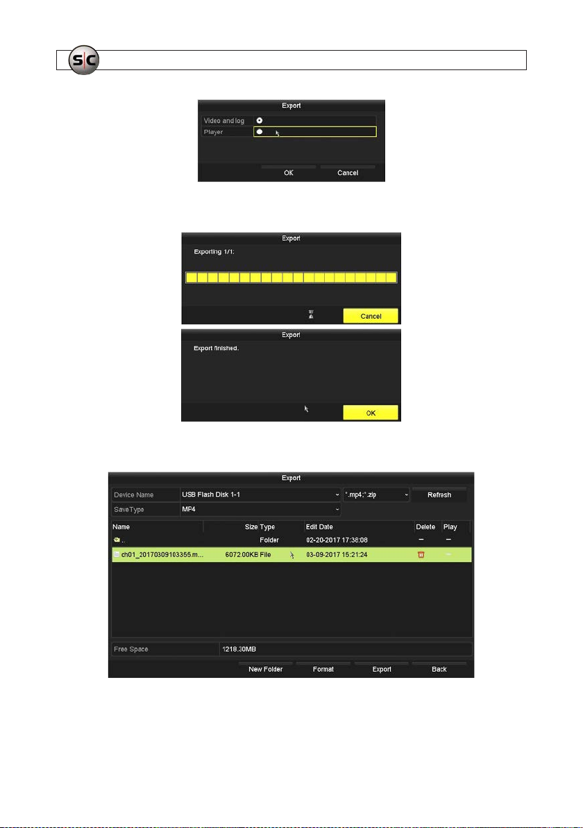
9. In the nex t Export window that opens, selec t either Video and log or Player, and then click OK.
41AVSI-11 Interview Room System Setup and User Guide
Page 46
SECTION 4: TEST/USE THE INTERVIEW ROOM SYSTEM
10. Allow the expor t operation to complete, and then click OK in the Export nished message window.
11. Verif y that the le you exporte d now appears in the director y on the ash drive.
12. Click the Back button to return to the previous menu.
42
www.Supercircuits.com
Page 47
SECTION 4: TEST/USE THE INTERVIEW ROOM SYSTEM
4.3.2 Using the Export menu to locate and export video les
In the Export menu, you can nd and expor t a video le in either of two ways:
• Using the Normal menu features
• Using the Event menu features.
Export using the Normal menu features
1. Right click anywhere on the Live View screen, and then click Menu in the popup list. NOTE: An Admin login window may
appear. If it does, enter your Admin password in the window, and then click OK to continue.
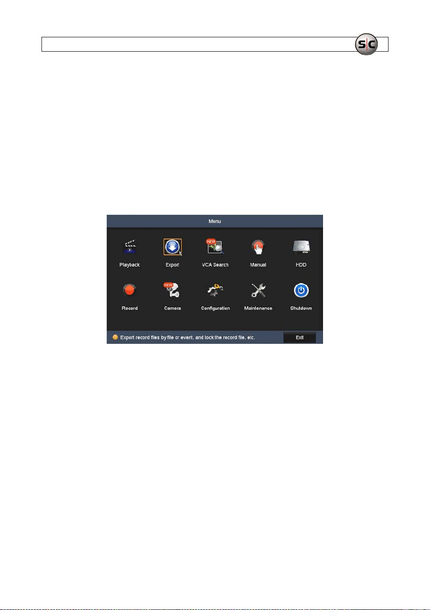
2. In the Menu window, click the Export icon.
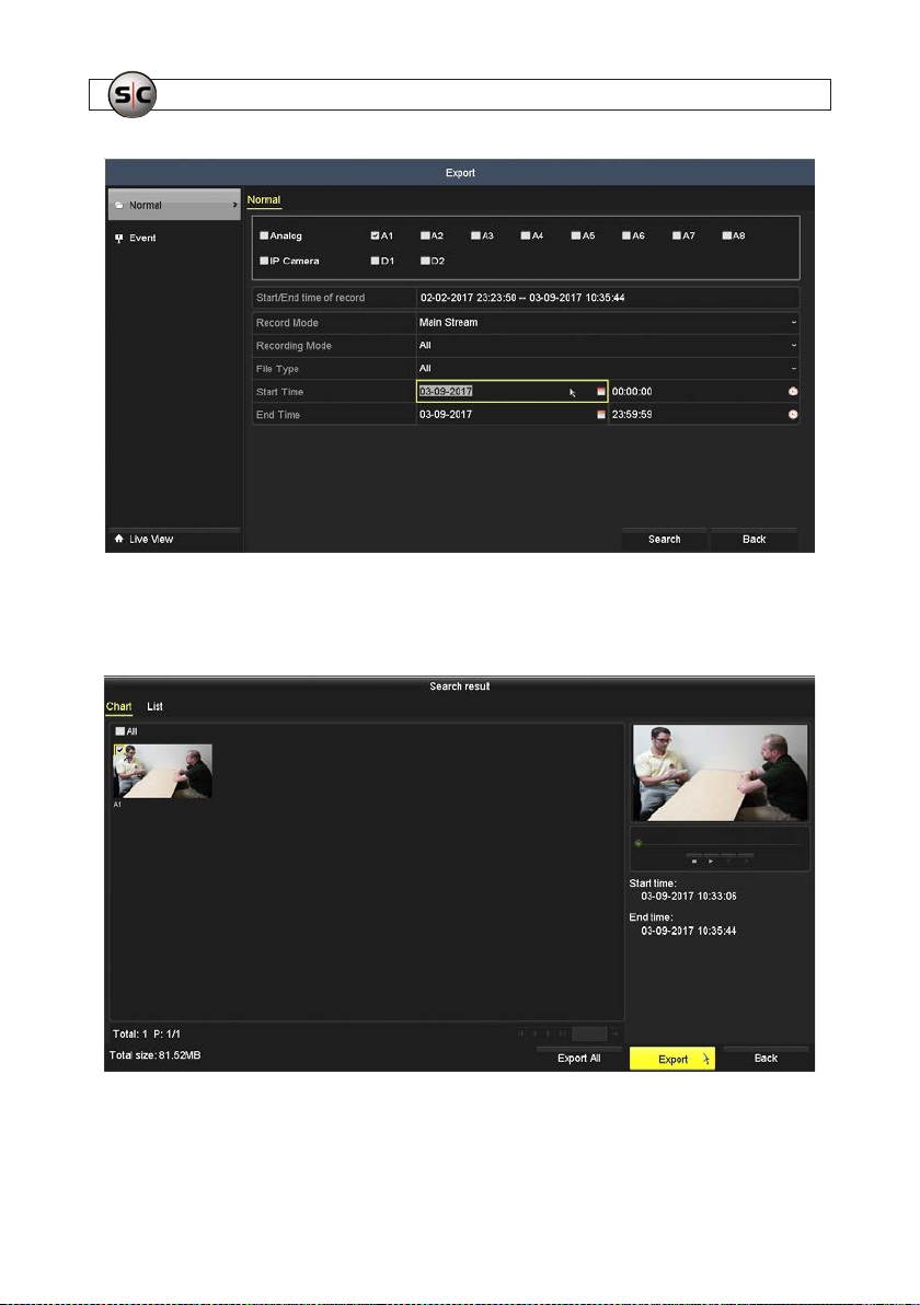
3. By default, Nor mal export mode is sele cted in the Export window. For eciency, deselec t the cameras that didn’t record the
video you want to ex port. Only camera A1 (the interview room camera) is selec ted here.
43AVSI-11 Interview Room System Setup and User Guide
Page 48
SECTION 4: TEST/USE THE INTERVIEW ROOM SYSTEM
4. Click the Start Time and End Time date and time elds to set the time span during which the video was recorded.
5. C lick Search. Search results will appear in a Chart (thumbnail) view.
6. Check the selec t box for the video le(s) you want to expor t, and then click the Export but ton. You can also view your search
results in List view. In List view, you can also Lock les.
44
www.Supercircuits.com
Page 49
SECTION 4: TEST/USE THE INTERVIEW ROOM SYSTEM
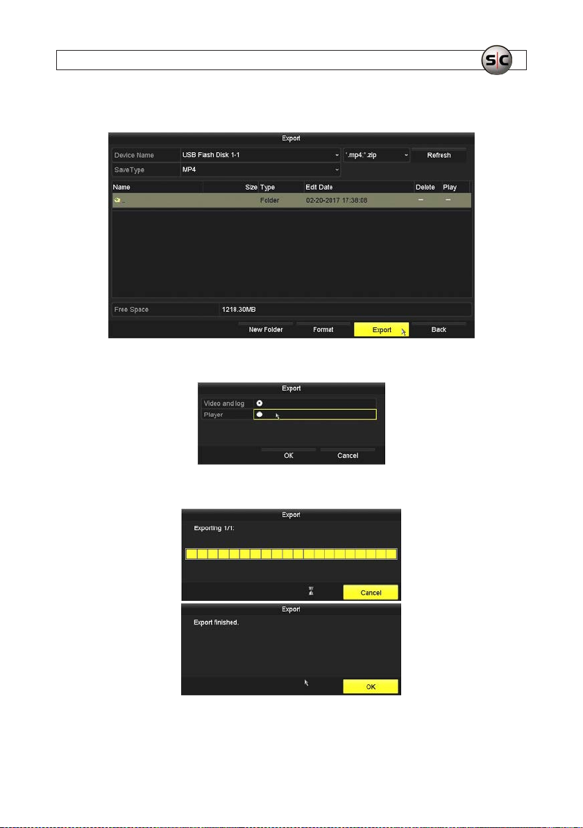
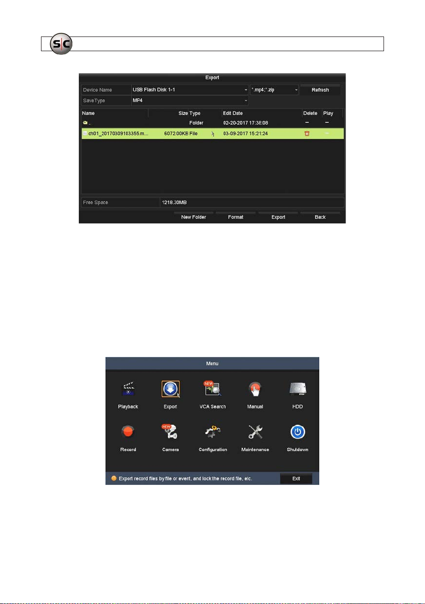
7. In the Export screen, open (double click on) the director y in the USB ash media drive, and then click Expor t to continue.
8. In the ne xt Export window that opens, select either Video and log or Player, and then click OK.
9. Allow the export operat ion to complete, and then click OK in the Export nished message window.
10. Verify that the le you expor ted now appears in the directory on the ash drive.
45AVSI-11 Interview Room System Setup and User Guide
Page 50
SECTION 4: TEST/USE THE INTERVIEW ROOM SYSTEM
11. Click Back to return to the Search result window.
Expor t using the Event menu features
In this example, we’ll search for the Alarm event (created by setting the AVSI switch to ON) that triggered a recording.
1. Right click anywhere on the Live View screen, and then click Menu in the popup list. NOTE: An admin login window may
appear. If it does, enter your Admin password in the window, and then click OK to continue.
2. In the Menu window, click the Export icon.
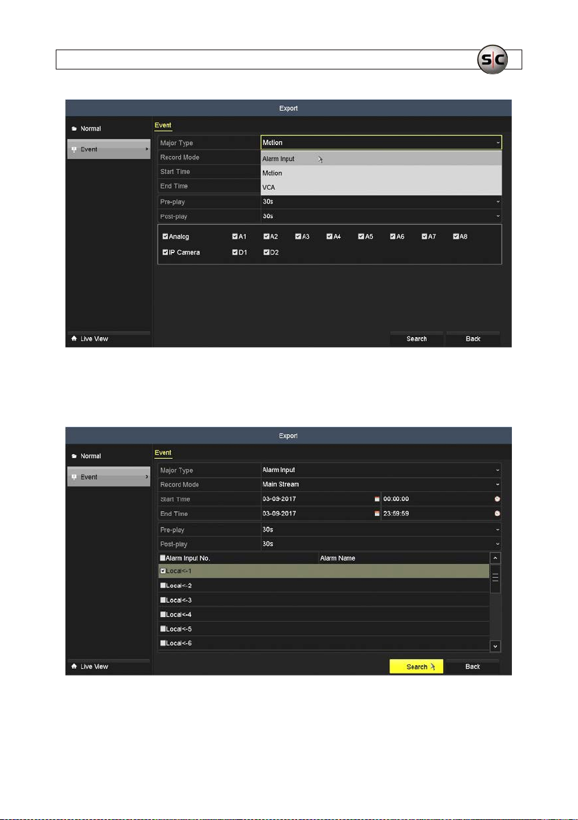
3. By default, Normal ex port mode is selected in the Export window. Click the Event option in the left f rame.
46
www.Supercircuits.com
Page 51
SECTION 4: TEST/USE THE INTERVIEW ROOM SYSTEM
4. With the Alarm Input Major event selected, select only the L ocal <-1 Alarm Input number f or eciency. Also, set the Start
Time and End Time dur ing which the event occurred. By default, the video and audio for 30 seconds before and 30 seconds
after the event will also be included.
5. C lick Search. Search results will appear in a Chart (thumbnail) view.
47AVSI-11 Interview Room System Setup and User Guide
Page 52
SECTION 4: TEST/USE THE INTERVIEW ROOM SYSTEM
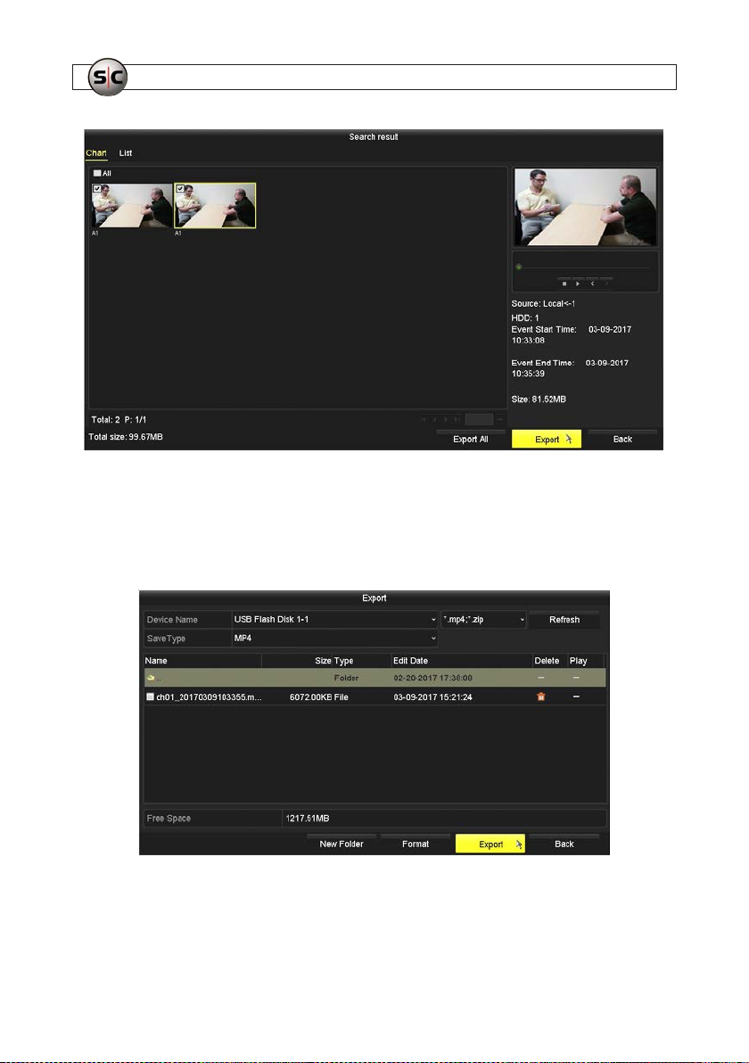
6. Check the selec t box for the video le(s) you want to expor t, and then click the Export but ton. In this example, both les
were selected. You can also view your search re sults in List view. In List view, you can also Lock les.
7. In the Export screen, open (double click on) the director y in the USB ash media drive, and then click Expor t to continue.
The le shown in that dire ctory below was saved previously.
8. In the ne xt Export window that opens, select either Video and log or Player, and then click OK.
48
www.Supercircuits.com
Page 53
SECTION 4: TEST/USE THE INTERVIEW ROOM SYSTEM
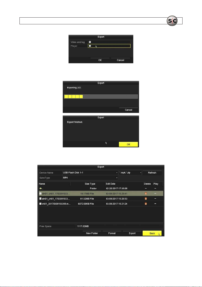
9. Allow the export operat ion to complete, and then click OK in the Export nished message window.
10. Verify that the les you expor ted appear in the director y on the ash drive in addition to the le expor ted earlier.
11. Click Back to return to the Search result window.
49AVSI-11 Interview Room System Setup and User Guide
Page 54
SECTION 4: TEST/USE THE INTERVIEW ROOM SYSTEM
4.4 Manual recording
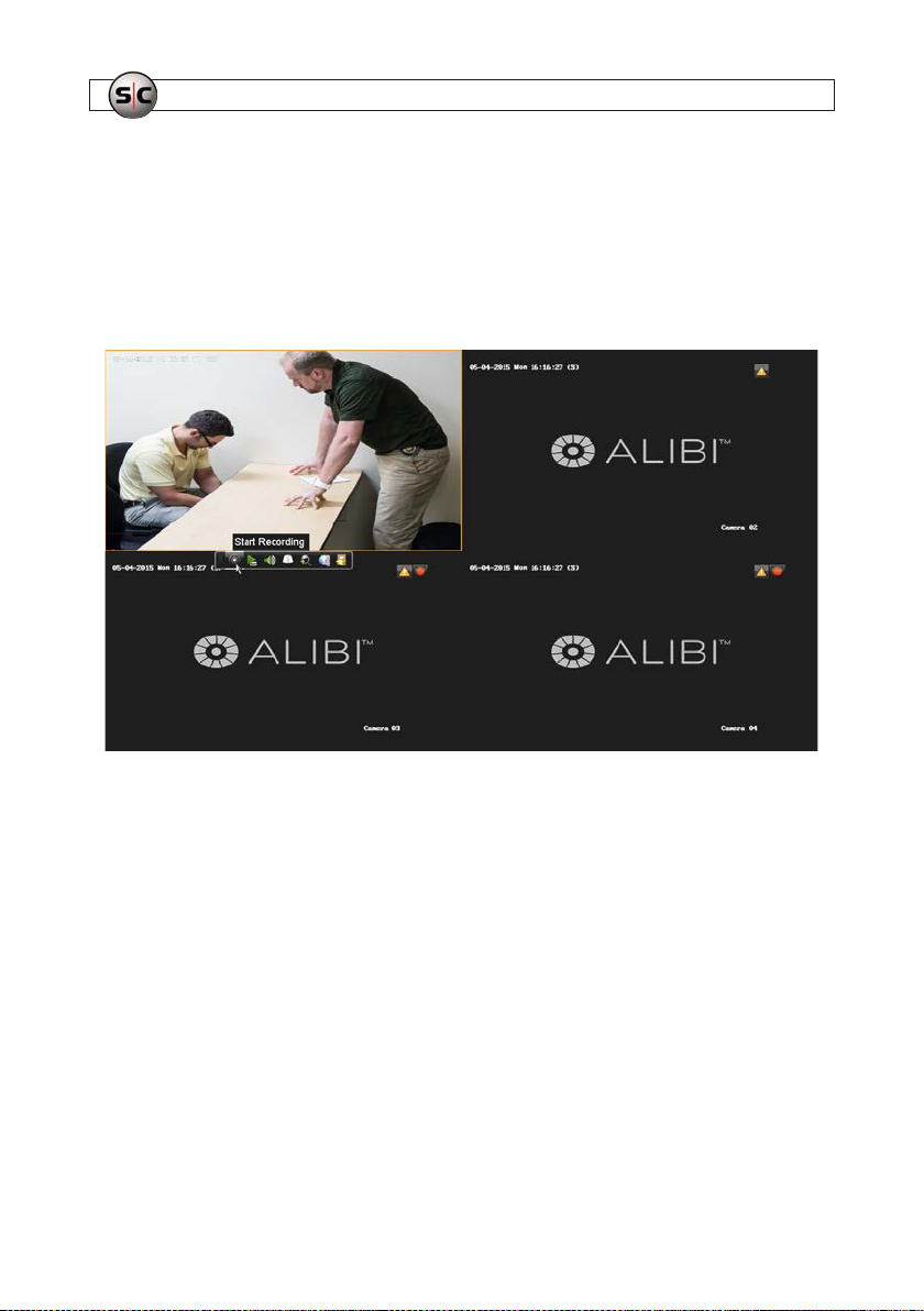
You can manually record Live View video and audio from your interview room without using the AVSI switch. When using t his
method, the gre en LED on the switch will not light.
1. To start recording, left click inside the Live View window you want to record, then click the Start Recording icon in the
quick setting toolbar. See below.
2. To stop recording, left click inside the Live View w indow you want to record, then click the Stop Recording icon in the quick
setting toolbar. See below. You can playback and search f or this recording as with any other recording.
50
www.Supercircuits.com
Page 55
SECTION 5: ADVANCED RECORDER FEATURES
SECTION 5
Advanced Recorder Features
Your Alibi ALI-QVR4008H recorder is a s tate-of-the-art high p erformance digital vide o recorder that includes most features of
enterprise class securit y systems. These features are included in the ALIBI Embedded Video Recorder Firmware User Manual for
your recorder provided elect ronically with the recorder. The most commonly used feat ures are listed below.
5.1 User Management
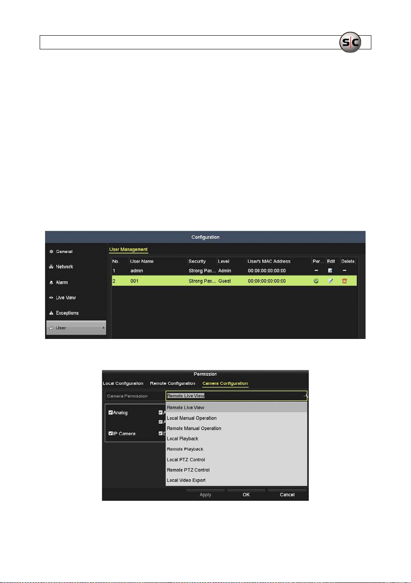
User accounts are created to control access to t he system both at the recorder and when logging into the recorder from a remote
computer. Each account has a User Name, Password, and a sele ction of permissions grante d to the user. The recorder support s up to
32 user accounts. To add, edit, and d elete user accounts, you must log into the recorder with admin user credentials. Refer to the
ALIBI Embedded Video Recorder Firmware User Manual for your recorder for more information.
User Management - user conguration
User Camera Conguration settings
51AVSI-11 Interview Room System Setup and User Guide
Page 56
SECTION 5: ADVANCED RECORDER FEATURES
5.2 Network Setup
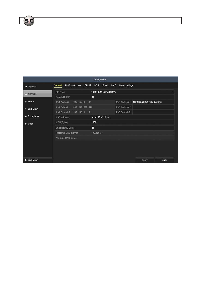
Network s ettings can be congured properly before you can connec t to the recorder remotely. By default, the recorder is not
congured for DHCP (Dynamic Host Conguration Processor - to acquire net work settings from the network’s Domain Name Ser ver
(DNS) or DDNS (Dynamic Domain Namve Server - for accessing the recorder conveniently from the internet).
Refer to the ALIBI Embedded Video Recorder Firmware User Manual for your recorder for more information.
Network Ge neral setup
The rmware also allows Alibi compatible cloud usage and DDNS.
5.3 Remote Access
If you recorder is connected to a loc al network (LAN), you can access it from another computer on the LAN through Microsof t®
Internet Ex plorer®. With remote access, you can view live video from the c ameras in use by the system, and search, playback and
download recordings. Also, you can manually record video and audio directly to the computer you use to access the recorder.
Remote access require s a login with a User Name and Password. User permissions c an disallow remote access to the recorder and/or
restric t access to features of the recorder.
Refer to the ALIBI Embedded Video Recorder Firmware User Manual for more information.
52
www.Supercircuits.com
Page 57
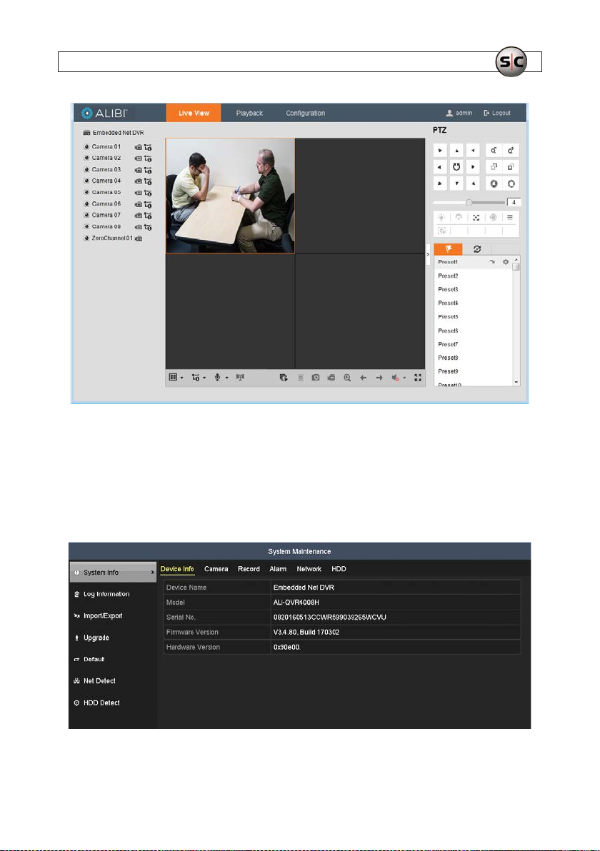
Remote Access Live View scre en (typical)
5.4 System Maintenance
SECTION 5: ADVANCED RECORDER FEATURES
The Maintenance menus prov ide several displays that report system device information, log information, and network tr ac.
Features also include the export and impor t of the system conguration le, rmware upgrade and factor y reset. Refer to the ALIBI
Embedded Video Recorder Firmware User Manual for more information.
System Maintenance menu
53AVSI-11 Interview Room System Setup and User Guide
Page 58

APPENDIX A: CONFIGURATION SETUP FOR THE INTERVIEW ROOM SYSTEM
APPENDIX A
Conguration Setup for Interview Room System
The Interview Room System is provided as a pre-congured turn -key system. However, if the system conguration is lost or
corrupted, it c an be reestablished in either of two ways:
• By import ing the default Interview Ro om System conguration le
• By reconguring the system manually.
This appendix provides the proce dure for manually recongure the sys tem to its default conguration.
54
www.Supercircuits.com
Page 59

APPENDIX A: CONFIGURATION SETUP FOR THE INTERVIEW ROOM SYSTEM
55AVSI-11 Interview Room System Setup and User Guide
Page 60

SECTION
56
www.Supercircuits.com
Page 61

SECTION
57AVSI-11 Interview Room System Setup and User Guide
 Loading...