

Page 1
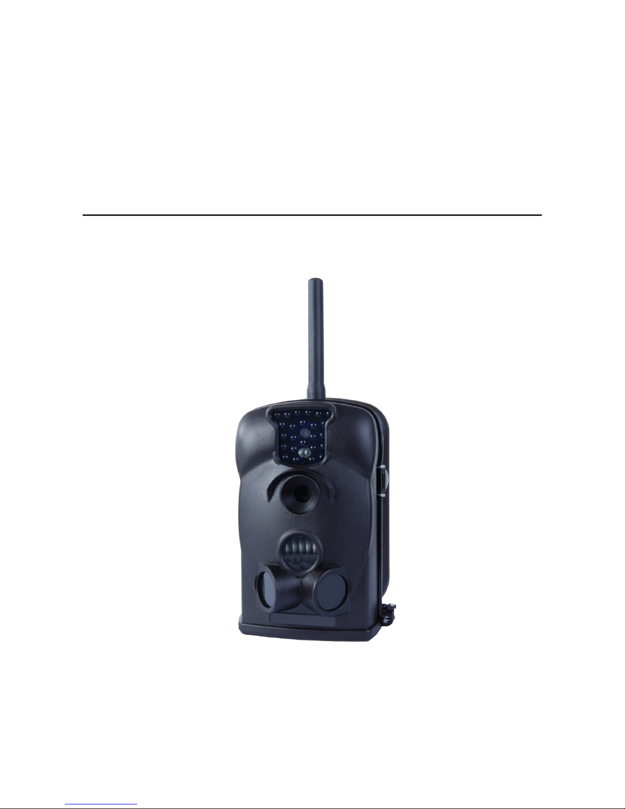
940 nm IR GSM
Field Surveillance Camera
User Manual
Product: 940-GSM
Please read this manual before using your camera, and always follow the instructions
for safety and proper use. Save this manual for future reference.
940-GSM_CM
9/13/13
Page 2
ii
CAUTION
Operate this device only in environments where the temperature or humidity is within the recommended range. Operation
in extreme temperatures or humidity levels may cause electric shock and shorten the life of the product.
Page 3

1
940 nm IR GSM Field Surveillance Camera
Table of Contents
SECTION 1 Features ...........................................................................2
1.1 Application .........................................................................2
1.2 Camera unit .........................................................................3
1.3 Camera module setup ................................................................4
1.3.1 Installing an SD card .............................................................6
1.3.2 Installing batteries in the camera module ...........................................6
1.3.3 Camera module controls ..........................................................7
1.4 MMS module setup ..................................................................8
1.4.1 Installing a SIM card .............................................................9
1.4.2 Installing batteries in the MMS module ............................................10
SECTION 2 Advanced Settings .................................................................11
2.1 Camera setup using the keypad control buttons .........................................11
2.2 Camera setup with a PC ..............................................................12
2.2.1 Camera function setup ..........................................................13
2.2.2 MMS function setup ............................................................14
SECTION 3 Using your camera .................................................................17
3.1 Aiming the camera ..................................................................17
3.1.1 ON mode ......................................................................17
3.2 Using MMS .........................................................................17
3.2.1 View Local MNPO name and signal strength ........................................18
3.3 Important notes ....................................................................19
3.3.1 Standby mode and capturing images ..............................................19
3.3.2 SD cards .......................................................................19
3.3.3 Auto adjustment of video length ..................................................20
SECTION 4 Specications .....................................................................21
APPENDIX A MMS Troubleshooting ..............................................................23
Page 4

2
SECTION 1: FEATURES
SECTION 1
Features
The 940-GSM Field Surveillance Camera is a rugged, water-repellent outdoor camera for use in extreme temperature conditions. It
includes the MMS (Multimedia Messaging Service) module for transmitting video and pictures to a phone or email address. With
its highly sensitive passive infra-red (PIR) sensor, the camera detects the sudden change of ambient temperature caused by moving
objects in a region of interest (ROI), triggers to take pictures/videos, and sends the images via a GSM network to the user’s cell
phone or email account. It includes:
• Programmable 1.3, 5, or 12-Megapixel photo resolution
• Infrared night vision LEDs for ash range as far as 30 feet
• Operates in either camera only, camera + video, or video only modes. In camera + video mode, camera takes both pictures
and video at every trigger event
• Ultra-low standby power consumption. Extremely long in-eld life (in standby mode, up to 6 months
• Unique side-prep sensor design provides wider sensing angle and enhances the camera response speed
• Perform in the temperatures from -22°F ~ 158°F
• Compact size (5 ½ x 3 ½ x 2 ½ inches). Designed to deploy covertly
• Quick trigger time (1.2 second)
• Time Lapse photo/video recording for takes pictures/videos at a specied interval
• Timer setting can program the camera to only work in specied periods every day. Work together with Time Lapse settings.
• Backpack-looking tree grabber makes mounting and aiming a snap
• Serial Number setting enables you to code locations on the photo. This helps multi-camera users identify the location when
reviewing the photos
• Built-in 2¼” TFT color display to review images and videos
• Date, time, temperature and moon phase can be stamped on the photo
• Lockable and password protected
• Two MMS image sizes: 640 x 480 or 320 x 240 pixels
• Users can congure the camera and MMS function either by running the enclosed CD with a computer, or directly on the
built-in TFT display.
• Advanced Remote Cellular Technology transmits images to your cell phone and email account constantly at low battery
consumption and short transmission time
• Automatically sends text alert when battery power level is low
• Checks cellular signal information on the built-in TFT display in the eld
• MMS pictures saved on a removable SD card
• Operates globally via GSM/GPRS network. Supports four bands: 850 / 900 / 1800 / 1900 MHz.
1.1 Application
• Trail camera for hunting
• Animal or event observation
• Motion-triggered security camera for home, oce and community
• Other indoor/outdoor surveillance where invasion evidence is needed
Page 5

3
940 nm IR GSM Field Surveillance Camera
SECTION 1: FEATURES
1.2 Camera unit
The 940-GSM Field Surveillance Camera includes two modules: a camera module and an MMS module. These modules are usually
latched together. To separate them, loosen the thumb screw on the back of the unit, undo the buckle on the side, then carefully
remove the tab of the camera module from the slot on the side of the MMS module.
Thumb Screw
Buckle
Thumb Screw on Back Camera and MMS Modules
Tab/Slot
Camera (left) sand MMS (right) Modules Unbuckled
Page 6
4
SECTION 1: FEATURES
1.3 Camera module setup
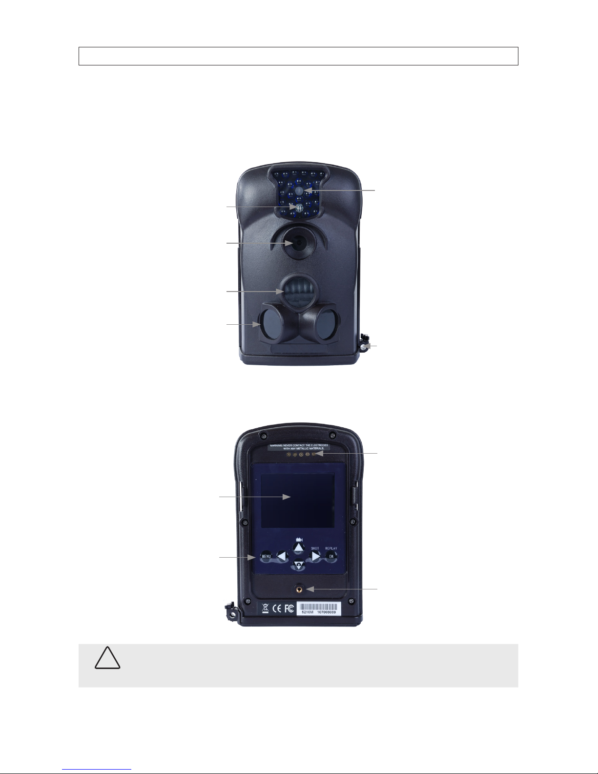
The camera module features a built-in infra-red (IR) array for taking photos up to 30’ away in dark environments, and built-in
passive IR (PIR) sensors for detecting objects moving into the region of interest (ROI).
IR Array
Camera
Lens
Light Sensor
Motion
Indicator
Main
PIR
Sensor
PIR
Sensors Bottom
Cover Latch
and
Lock Ring
TFT display and keypad on the back of the camera module are for setup, programming, and viewing recorded video and photos.
Setup, programming, and viewing recorded videos and photos can also be performed through a USB connection to a computer.
Thumb
Screw Hole
Contact
Pads for
MMS
Module
TFT
Display
Keypad
Bottom
Cover
Latch
CAUTION
When batteries are installed in the camera, do not touch the Contact Pads with any electrically conductive material. .
Page 7
5
940 nm IR GSM Field Surveillance Camera
SECTION 1: FEATURES
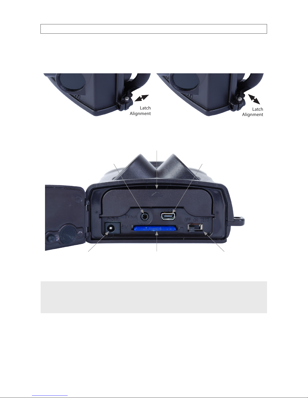
The camera external interface connectors are located Inside the cover on the bottom of the camera module. To open the bottom
cover, turn the latch on the lower corner so it points toward the body of the camera, then push it down to open the cover.
Latch
Alignment
Latch
Alignment
Cover Latched Unlatched
Battery Bay Cover
(Press here to open)
TV Out Jack
6 - 12 VDC Power Adapter Socket
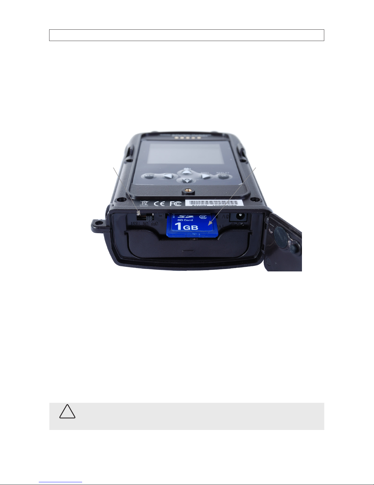
SD Card Slot
USB 2.0 Connector
OFF - ON - TEST Power Switch
The external interface connectors include a video out jack, USB 2.0 port, 6 VDC power adapter socket, and SD card slot.
NOTE
The camera will accommodate an SD, MMC, and SDHC ash memory card up to 16 GB. Always set the power switch to
OFF when installing a ash memory card.
When installing a ash memory card, make certain that it is NOT congured for write protection.
A power adapter, TV out cable, batteries, and ash memory card are not included.
Page 8
6
SECTION 1: FEATURES
1.3.1 Installing an SD card
To install an SD (ash memory) card:
1. Set the power switch to o.
2. Slide the card into the SD card slot as shown below. The card should slide in smoothly.
Power Switch SD Card
3. Push the SD card in until it latches into place.
The camera stores pictures and videos on the SD card in the folder \DCIM\100IMAGE, and all MMS pictures in the folder \DCIM\
MMS\100IMAGE with the same lename. Photo lenames are similar to IMAG0001.JPG, and videos appear as IMAG0001.AVI.
In OFF mode, you can use the USB cable provided to download the les to a computer, then browse and play les without
downloading them. AVI les can be played back on most popular media players, such as Microsoft® Windows Media® Player,
Apple® QuickTime®, etc.
1.3.2 Installing batteries in the camera module
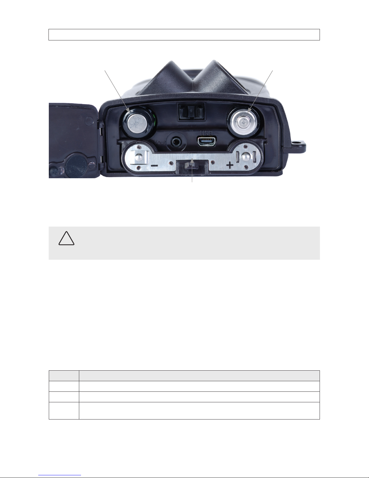
To open the battery bay, press down the triangle icon on the battery bay cover. The camera module requires 4 AA alkaline batteries.
CAUTION
Always set the power switch to OFF o before installing or removing batteries.
Page 9
7
940 nm IR GSM Field Surveillance Camera
SECTION 1: FEATURES
Battery Bay Cover
Insert 2 AA Batteries Here,
“–” Ends toward Base.
Insert 2 AA Batteries Here,
“+” Ends toward Base.
After installing batteries, fold the battery bay cover up, then press it in until it latches. To perform software setup for the camera,
refer to Section 2 of this manual.
CAUTION
If you are not using the camera for an extended period of time, remove the batteries from the camera to avoid possible acid
leak that may damage the camera and void the warranty.
When battery level gets low, the Motion Indicator in the LED array will ash blue. If using the MMS module with a SIM card, a
Battery Low text alert will be sent automatically to the user’s cell phone or email account.
1.3.3 Camera module controls
The camera module includes two control components: an ON - OFF - TEST power switch, and a keypad control panel. The switch
is accessible when the bottom cover is open, and the keypad is on the back side of the camera module. These controls function as
follows:
Power Switch
Position Function
OFF Unit is powered o.
ON Unit is in normal operating mode.
TEST Camera module is in setup mode. In this mode you can take pict ures or video clips like a re gular digital camera, or enter the Menu to set up the
system conguration.
Page 10
8
SECTION 1: FEATURES
Keypad control panel
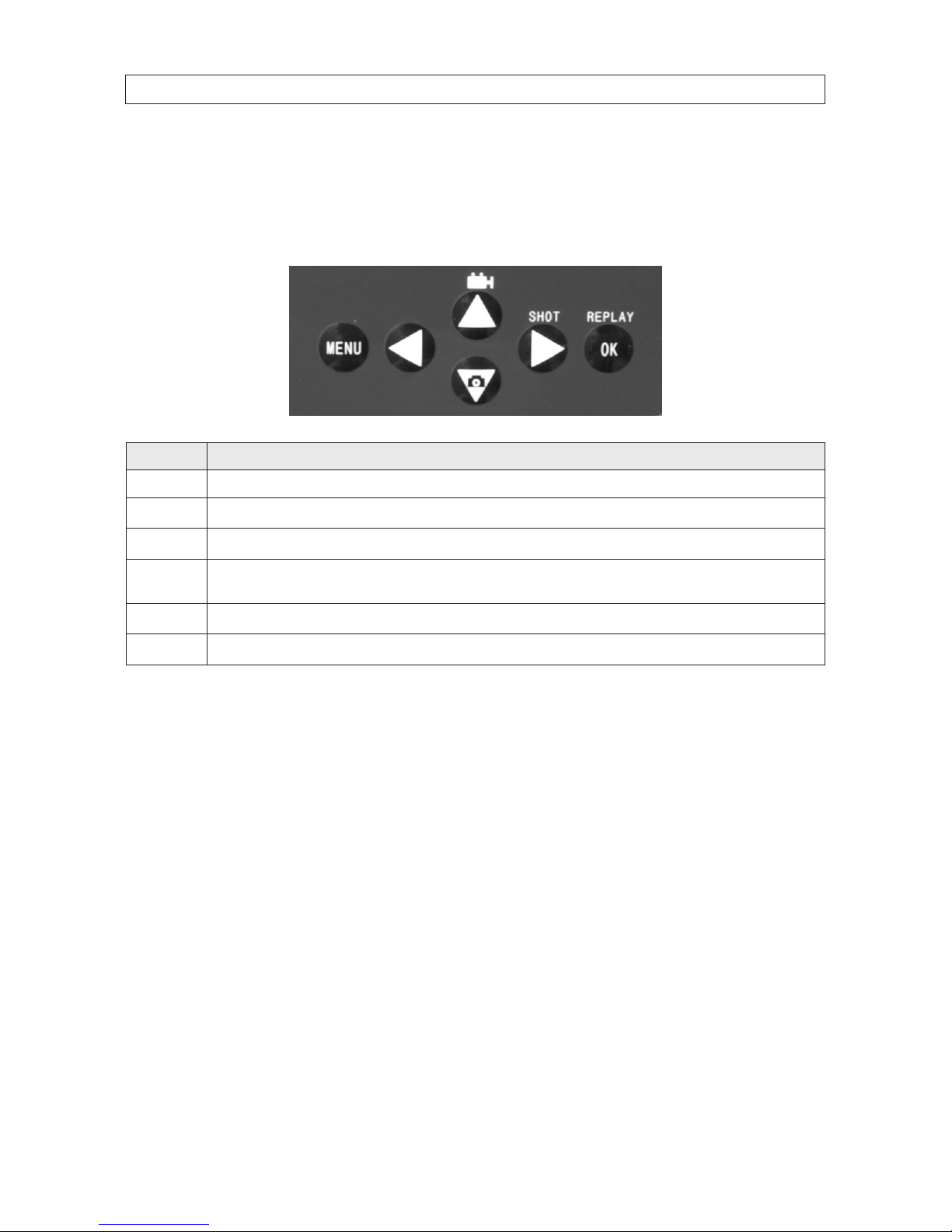
The keypad control panel us used for conguration setup , manual camera operation, and for viewing and playing back recorded
photos and video.
Button Function
MENU Press to enter the congur ation menu sys tem to program t he camera.
t
Press when nee ded to navigate in the menu s ystem.
p (vid eo)
Press to shoot a video segment.
u (shot)
Press SHOT to manually trigger the shutter. A photo or video (depending on the camer a setting) will be taken and save d to the SD card. If the
display shows
q (ph oto)
Press to take a still pict ure..
REPLAY / OK
Press REPLAY to review/playback photo s or videos on the TFT screen or a connec ted TV monitor. Use and p and q keys to navigate.
1.4 MMS module setup
The MMS module provides two functions: expanded power capacity, and access to Multimedia Messaging Service (MMS). To use
the MMS module for transmitting images or messages, you must acquire a SIM card from a local Mobile Phone Network Operator
(MPNO) that provides MMS. Use the parameters suggested by your provider when conguring MMS features. (Refer to the
Advanced Settings section for more information.)
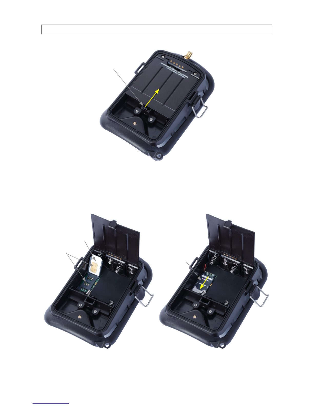
To access the SIM card holder and battery compartment, open the cover by pushing up on the tab, then folding the cover up.
Page 11
9
940 nm IR GSM Field Surveillance Camera
SECTION 1: FEATURES
Tab
Push to unlock
1.4.1 Installing a SIM card
To install a SIM card, open the card holder and slide the card all the way into the card holder as shown below. Then fold the card
holder onto the contacts, and slide the card holder towards the bottom of the unit to lock it into place.
SIM Card
Card
Contacts
SIM Card
Holder
Lock
SIM Card Inserted SIM Card Installed
Page 12
10
SECTION 1: FEATURES
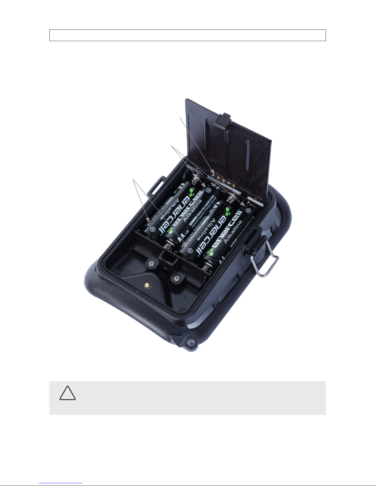
1.4.2 Installing batteries in the MMS module
When installing batteries in the battery compartment, follow the (sardine) orientation order shown below.
Put Positive Terminals For
These Batteries Here.
Put Positive Terminals For
These Batteries Here.
Camera module
Contact Pins
After installing batteries, close the battery compartment cover.
CAUTION
When batteries are installed in the MMS module, do not touch the Camera Module Contact Pins with any electrically
conductive material.
Page 13
11
940 nm IR GSM Field Surveillance Camera
SECTION 2: ADVANCED SETTINGS
SECTION 2
Advanced Settings
Advanced settings can be congured using the TFT display and keypad control buttons, or through a computer.
2.1 Camera setup using the keypad control buttons
To enter camera setup mode:
1. Separate the camera and MMS modules.
2. Install batteries in the camera module.
3. Set the power switch to TEST.
4. Install an SD card in the camera module.
5. Press the MENU button on the keypad, then use the p, q, t, and u buttons to navigate through the menu system and
select parameters. After specifying the preferred parameters, press OK to save the settings exit the menu system. Menu
system parameters are described below.
Menu system parameters
Parameter Setting Description
Mode Camera, Video,
or Cam + Video
Selec t whether still photos or video clips are taken. In Cam+Video mode, th e camera rst shoots a
photo, th en records video. .
Format Enter Selec t to format the SD card. All les on the card are deleted during f ormatting. It is highly
recomm end that you for mat the SD card before use, especially if it has been used in another device.
Caution: Make sure all impor tant les on the SD card have b een backed up before format ting.
Photo Size
(aects still photos only)
5 MP, 12 MP, 1.3 MP Select preferred re solution for still photos from 1.3 to 12 mega pixels. Higher resoluti on produces
better quality photos, but creates larger les that use more space on the SD c ard. Also, large le s
requir e longer time to wr ite to the card, which will slow the shutter speed. 5 MP is recommende d.
Video Size
(aects video clips o nly)
640 x 4 80,
320 x 240
Selec t video resolution (pixels p er frame). Higher resolution produces b etter qualit y videos, bu t
create s larger les that use more of the SD card capac ity.
640 × 4 80 is VGA mode in s tandard 4:3 for mat.
Set clock Enter Press Enter to set up date and time. An inter nal capacito r will maintain the clock f or up to 7
minutes when changing batteries.
Picture no.
(aects still photos only)
01 Photo, 02 Photos,
03 Photos
Selec t the number of photos taken in sequence per burst in Camera mode.
Also refer to the Interv al parameter.
Video Length
(aects video clips o nly)
AVI 10 seconds,
optional from 1 second
to 60 seconds
Video s are in AVI format that can be played back on most media players.
Page 14

12
SECTION 2: ADVANCED SETTINGS
Parameter Setting Description
Interval 1 minute, o ptional from
1 second to 60 minu tes
Selec t the length of t ime that the cam era will wait between the time of the last picture was written in the SD card, unt il it responds to any new tr iggers from the PIR sensor. Dur ing the selec ted
inter val, the camera w ill not take pict ures/videos. This p revents the SD c ard from lling with
redundant images.
Sense Level Normal, High, Low Selec t the sensitivity of the PIR s ensor. The High se tting is bes t for indoor s and environments with
little inter ference. Nor mal or Low works well when outdoors and in environments with more
interference.
NOTE: Temperature als o aects the sensi tivity. The High set ting is suitable when th e
ambient temperature is warm, and the Low set ting works better in cold weather.
Time Stamp
(aects still photos only)
On, O Selec t On if you want the date and time to appear on ever y photo.
Timer O, On Select On if you want the camera to work within a specied time perio d every day. For ins tance,
if the start ing time is set at 18:35 and the ending time at 8:25, the c amera will functio n only from
18:35 the cur rent day to 8:25 the next day. Outside the time period the camera will not triggered or
take photos/videos. This feat ure can be used togeth er with Time Lapse feature.
Password set O, On Set up a password to protect your camera from unauthorized users.
Serial No. O, On Sele ct On to assign a numb er to each camera you have. You can u se a combination of 4 digit s
and/or alphabet s to record the location in the photos (e.g. YSP1 for Yellow Stone Park). This helps
multi-camera user s identify the location wh en reviewing photos.
Time Lapse O , On If On, the camera will automatic ally take photos/videos at the set inter val (Note: in this mode,
the PIR sensor is disabled). This is helpful w hen observing cold-blooded animals like snakes, the
process of owering, etc . This feature c an work together with Timer feature.
Side PIR On, O Set to On by def ault. The two side prep PIR sensors provide a ver y wide sensing angle and enhance
response time. In locations where you cannot removing interfering object s or avoid sunlight, you
can tur n o the side sens ors to improve performance.
MMS Phone No. On Press Enter to input the phone number you want to send MMS to. To input more phone numbers
or to set up email accounts, referen ce the MMS Function setup on a PC. Set the number of pictures
sent in on e day via MMS. Select 0 for u nlimited, 1 .. 99/day to set a limite d number.
MMS Status O, VGA, QVG A The default set ting, O, turns the MMS f unction o. To turn it on and set the resolution, select ei-
ther VGA (640 x 48 0) or QVGA (320 x 240). If the original pic ture size is too large, the MMS picture
is conver ted to QVGA format to save t ransmission t ime and power consumption.
Default Set Press OK then Enter to revert all camera se ttings to the manufacturer default values. MMS f unction
settings will remain as congur ed except for MMS Phone No. and MMS Status.
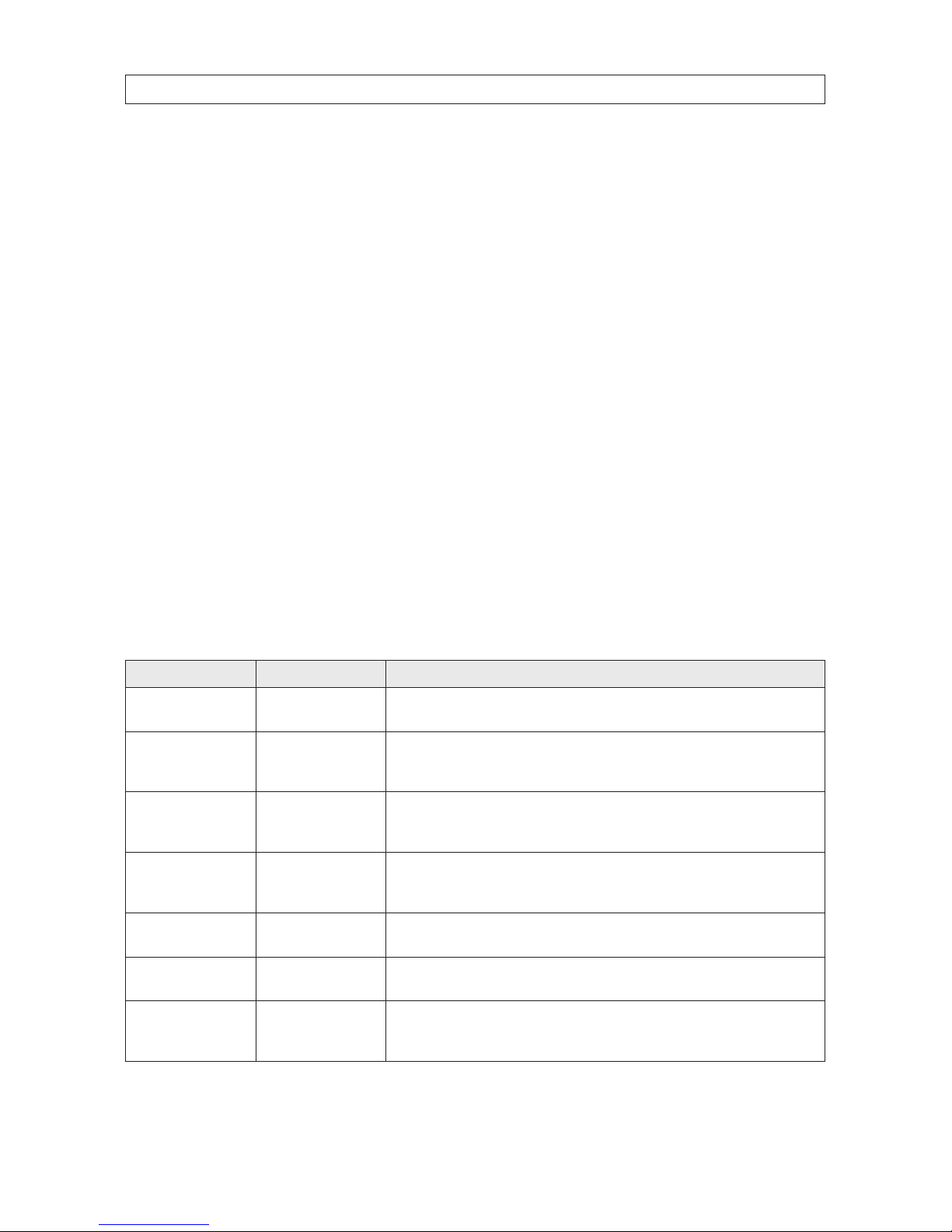
2.2 Camera setup with a PC
You can set up your camera and/or MMS function with a PC. Insert the CD provided into an optical drive on a Microsoft Windows
PC, then open it in a le explorer.
Page 15
13
940 nm IR GSM Field Surveillance Camera
SECTION 2: ADVANCED SETTINGS
In the MMS Setup subdirectory, nd and run the Setup.exe le. The following window will open:
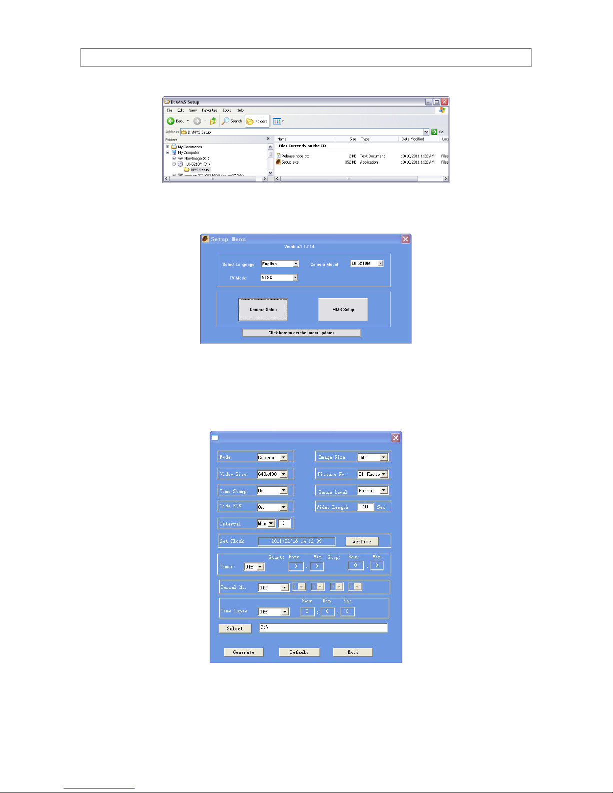
2.2.1 Camera function setup
Click the Camera Setup button to open the camera interface shown below.
In the camera setup menu, do the following. Refer to the Menu system parameters table above for more information.
Page 16

14
SECTION 2: ADVANCED SETTINGS
1. Select the Mode, Image Size, Video Size, etc. options you prefer from the drop-down menus.
2. Set the Timer, Serial No., and Time Lapse menu setup as needed.
3. Click the GetTime button to set the camera’s date and time to your computer’s date and time.
4. Power o the camera if necessary, then connect the camera USB interface to the computer using the USB cable provided.
Wait for the computer to recognize the USB device (your SD card).
5. Click Select, then choose the root directory of the SD card for the location for saving your settings. Normally, the USB device
appears an the E drive (E:/ ).
6. Click Generate. A le named menu.dat will be written to the root directory of your SD card.
7. Click Exit.
NOTE
To return settings to the manufacturers default values, click Default.
8. Eject the USB device (your SD card) from the Windows operating system, then disconnect your camera USB cable from the
computer and camera.
9. Set the camera ON - OFF - TEST power switch to the TEST position. Wait for a message to appear on the TFT display that the
camera has been successfully setup.
10. Set the OFF - ON - TEST power switch to OFF.
11. Close the bottom cover and turn the latch to lock the cover closed.
12. If you are not setting up or using MMS functions with your camera:
a. Install batteries in the MMS module.
b. Connect the MMS module to the camera module. Reverse the instructions above for separating the two modules.
c. Attach the antenna to the MMS module. Although the antenna is not used without MMS functionality, it will protect
the antenna connector from contamination.
d. Continue with the section below: Using your camera.
2.2.2 MMS function setup
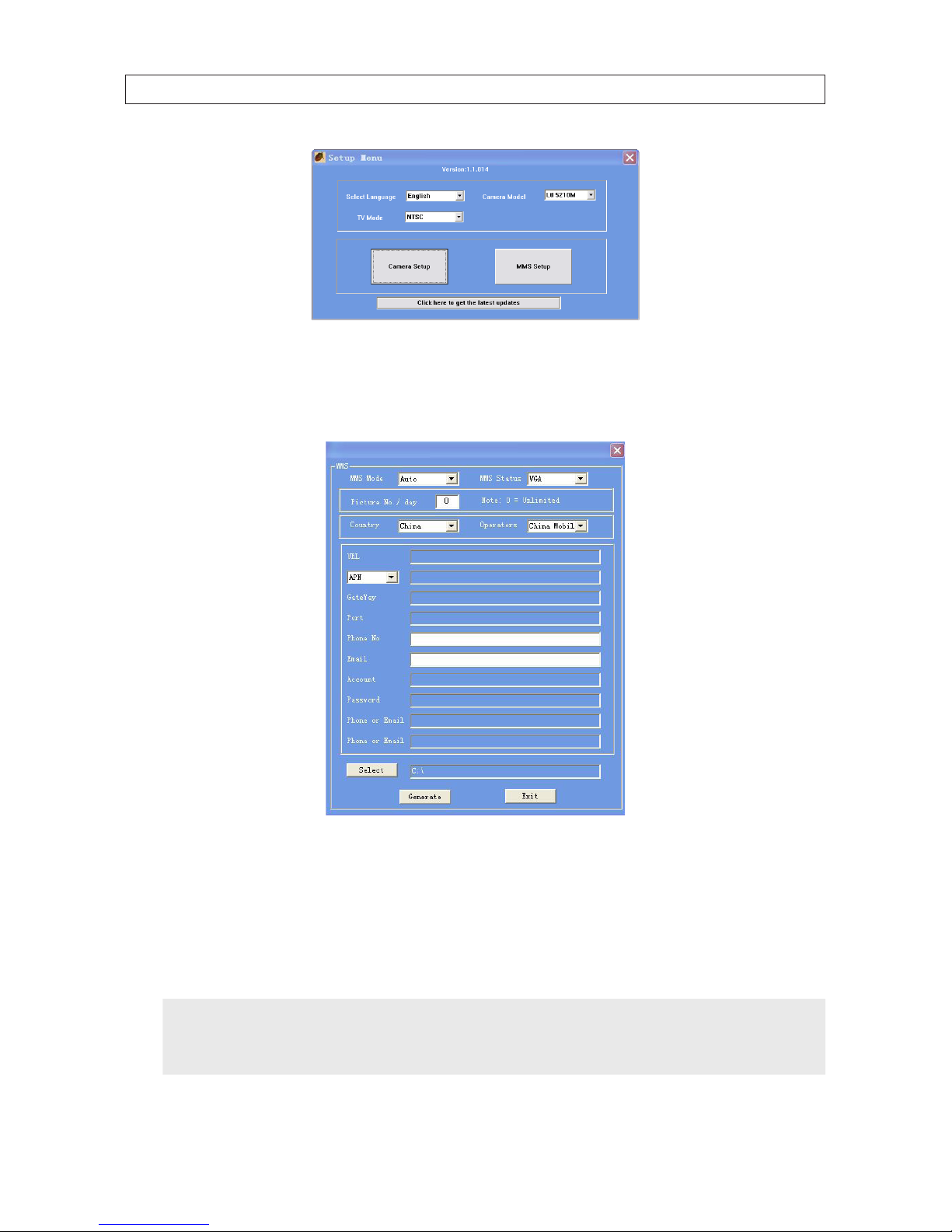
After performing the Camera Setup and clicking Exit, the Setup Menu screen will reappear on your computer. If the Setup Menu
screen is not open, repeat the step above in the Camera function setup procedure to open the window.
Page 17
15
940 nm IR GSM Field Surveillance Camera
SECTION 2: ADVANCED SETTINGS
To setup the MMS functions, do the following:
1. Click MMS Setup. The MMS window will open.
2. Open the MMS Mode drop-down list and select either Auto or Manual.
Auto: If you selected Auto, open the Country drop-down list and select your country and the Mobile Phone Network
Operator (MPNO) for your SIM card. The section below will populate with parameters pertaining to the selected MPNO,
including URL, APN, Gateway and Port. APN, Gateway and Port. Enter up to three phone numbers (format: 10 digits of area
code plus phone number, ex. 8003359777) and email address where you want pictures sent.
NOTE
Settings for each major MPNO are pre-stored on the enclosed CD. But, because each MPNO has specic
settings for their service, and those settings can change over time, we recommend you verify all settings with
your MPNO.
Page 18

16
SECTION 2: ADVANCED SETTINGS
Manual: If you selected Manual, contact your MPNO for the required information to use their service, then enter the
parameters in the elds below.
3. Power o the camera if necessary, then connect the camera USB interface to the computer using the USB cable provided.
Wait for the computer to recognize the USB device (your SD card).
4. Click Select, then choose the root directory of the SD card for the location for saving your settings.
5. Click Generate. A le named setup.dat will be written to the root directory of your SD card.
6. Click Exit.
7. Eject the USB device (your SD card) from the Windows operating system, then disconnect your camera USB cable from the
computer and camera.
8. Set the camera ON - OFF - TEST power switch to the TEST position. Wait for a message to appear on the TFT display that the
camera has been successfully setup.
9. Set the OFF - ON - TEST power switch to OFF.
10. Close the bottom cover and turn the latch to lock the cover closed.
11. Install batteries in the MMS module, then connect it to the camera module. To connect the camera and MMS modules,
reverse the instructions above for separating the two modules.
12. Attach the antenna to the MMS module. The antenna connector is at the top of the MMS module.
Page 19

17
940 nm IR GSM Field Surveillance Camera
SECTION 3: USING YOUR CAMERA
SECTION 3
Using your camera
3.1 Aiming the camera
With the power switch in TEST mode, you can test the working area of the PIR (passive infrared) sensor sensing angle and distance.
Using this test you can nd the best placement for mounting and aiming the camera. To perform the test:
• Attach the camera to a tree or tripod, aiming it at the region of interest (ROI). Supercircuits recommends that the camera
be placed 3 to 6 feet (1 to 2 meters) above the ground. To avoid potential false triggers due to temperature and motion
disturbances, do not aim the camera at a heat source (i.e. the sun) or nearby tree branches and limbs. If possible, aim the
camera North or South. Also, avoid placing the camera where limbs and other objects are close to the front of the camera.
• Walk slowly from one side of the ROI to the other, parallel to the camera. Try dierent distances and angles from the camera.
• If the Motion Indicator ashes blue, your position is detected by one of the side Prep PIR sensors. If the Motion Indicator
ashes red, your position is captured by the main PIR sensor.
3.1.1 ON mode
Set the power switch to the ON position to enter the normal operating mode. The Motion Indicator will ash red for about 10
seconds and the camera starts working as programmed without any manual handling. If the camera is setup to record on motion
detection, it will wait in standby (low power) mode, and power up to shoot pictures or record videos when objects enter the PIR
area of the main sensor as follows:
• When an object enters the PIR area of the side prep sensors, the prep sensors detect the movement and fully powers up the
camera.
• When object moves into the PIR area of the main sensor, the camera takes photos/videos immediately. If the object moves
away after entering the PIR area of the prep sensors, the camera will revert to standby mode to conserve power.
• If the object is not detected in the PIR area of the main sensor after being detected by a prep sensor, the camera reverts to
standby mode in 3 seconds. If an object(s) is detected a second time by the prep sensor, without being detected by the PIR
area of the main sensor, the camera will not wake from standby mode until the object is detected by the main sensor (1.2
seconds later).
3.2 Using MMS
After your camera is setup for MMS functionality, it can transmit photos to your email and phone if the following conditions are met:
• The camera is ON and functions normally.
• The SD card has enough space.
• Four batteries are installed in the camera module and four batteries are installed in the MMS module. The batteries must
have sucient power capacity.
• The camera mode is set to Camera mode or Cam+Video mode. It cannot be set to Video mode.
Page 20
18
SECTION 3: USING YOUR CAMERA
• SIM card is installed and the MMS service is active. (NOTE: Some MMS services require pre-paid balance in the account.)
• The SIM card is not password protected.
• MMS function setup is correct.
• The Timer function is OFF. If the Timer ON, expect to receive photos through MMS only during specied time period.
• Ensure that the MMS Status parameter is NOT set to OFF or SMS.
• The Picture No./day parameter is set to “0” (unlimited) or the maximum number of pictures sent per day (1 ~ 99) has not
been reached.
• The camera is stationary while sending MMS pictures.
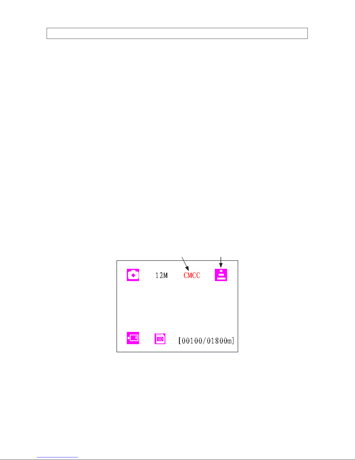
3.2.1 View Local MNPO name and signal strength
WIth the camera and MMS modules connected and an antenna attached:
Using a TV monitor:
a. Open the bottom cover, than attach a video cable between the TV OUT connector on the camera and a composite
video input on a TV monitor.
b. Set the power switch on the camera to TEST.
c. Wait for at least 1 minute, or until you can see the MPNO name and the signal strength on the monitor. The MNPO
signal strength must be at one bar or more for MMS functionality.
MNPO Service Provider Signal Strength
d. Set the power switch on the camera to OFF.
e. Disconnect the cable between the camera and the monitor.
Page 21

19
940 nm IR GSM Field Surveillance Camera
SECTION 3: USING YOUR CAMERA
Without a TV monitor:
a. Set the power switch on the camera to TEST.
b. Wait for at least 1 minute.
c. Without powering o the unit, separate the camera module from the MMS module.
d. View the TFT screen. The MNPO name and signal strength will appear on the screen. The MNPO signal strength must
be at one bar or more for MMS functionality.
e. Set the power switch on the camera to OFF.
f. Reattach the MMS module to the camera module.
NOTE
If a code, instead of MPNO information, appears on the screen, an exception condition occurred:
- SIM: No SIM card or installed incorrectly.
- CSQ: No signals.
- CREG: SIM card is password-protected, deactivated due to zero balance in the account, or not able to register with a GSM system.
- CGREG: Not able to register with GPRS network.
- COPS: Searching for the MNPO of the SIM card. When found, the MNPO name and signal strength will appear.
- No MM1: MMS module is not found (installed). The buzzer will issue three short tones (“di di di”).
3.3 Important notes
3.3.1 Standby mode and capturing images
To save battery power during normal operation, the camera is in “standby” mode, with only the PIR sensor working. When an
object is detected by the PIR sensor, the camera is becomes fully powered on and starts shooting pictures. The time period from
being activated to starting recording is about 1.2 seconds. Therefore, when an object passes across very quickly past the camera, the
picture may only capture the end part of the object body, and possibly nothing at all.
In the 940-GSM camera, the combination of the two side prep sensors and the main sensor provides a 100° to 120° angle of
induction, a very wide scope far out spanning the 50 ° angle of the camera lens. It can capture the whole body of a moving object in
as short as 0.2 second.
3.3.2 SD cards
Several dierent brands of SD cards have been tested and found to be compatible with the camera. However, some brands and
models may not function well. If you encounter a problem with an SD card, reformat the card and try it again. If it still does not
work, try another size or brand of card.
Page 22

20
SECTION 3: USING YOUR CAMERA
3.3.3 Auto adjustment of video length
To extend the battery life, we suggest that you install 8 AA alkaline batteries when using the camera in Video mode or Cam+Video
mode. When battery power gets low, this camera automatically shortens the video length to take more video clips of surveillance
targets, which can provide more useful information.
Very cold environments can signicantly reduce battery power capacity, reducing the length of video clips accordingly.
Page 23
21
940 nm IR GSM Field Surveillance Camera
SECTION 3: SPECIFICATIONS
SECTION 4
Specications
Item Specication
Image sensor 5 Mega Pixels Color CMOS
Maximum pixel size 2560 x 1920
Lens F = 3.1; FOV = 52°; auto IR-c ut
IR Flash 30 ft (9.14 m)
TFT screen 2.36” (48 x 35.69 mm); 480 (RGB)*234 dots; 16.7 M colors
Keypad 6 keys
Memory SD card (8 MB ~16 GB)
Picture size 5 MP / 12 MP / 1.3 MP = 2560 x 1920 / 4000 x 3000 / 1280 x 9 60
Video size 640 x 4 80 @ 20 fps, 320 x 240 @ 20 f ps
PIR sensitivity High / nor mal / low
PIR sensing distance 30 ft (9.14 m) (< 77°F (25°C) at the normal leve l)
Prep PIR sensing angle Lef t and right light beams for m an angle of 100°; each lens covers 10°
Main PIR sensing angle 35°
Operation mode Day / night
Trigger time 1.1 second (when using a 2G SD card)
Trigger interval 0 sec ~ 60 min, programmable
Shooting numbers 1 ~ 6
Video length 1 ~ 120 sec, programmable
Cam + Video Take picture rst, then record video
Playback zoom in 1x ~ 16x
Time stamp On / O, inc ludes serial No., temperature and moon phase
Timer On / O, pro grammable
Password 4-digit numbers
Device s erial no.. 4 di gits of and 26 alphabet characters, us er set
Time lapse On / O, 1 se c ~ 24 hr, programmable
MMS status VGA = 64 0 x 480; QVGA = 320 x 240;SMS; OFF pro grammable
MMS numbers 0 = unlimited, or 1 ~ 99 / day
MMS phone no. 1 ~ 3 phone nu mbers
MMS email 0 ~ 3 email addre sses
SMS 1 ~ 3
Page 24

22
SECTION 4: SPECIFICATIONS
Item Specication
Low battery SMS alert “Battery Low” text alert sent
Power supply 2 x 4 x AA bat teries
External DC power adapter Plug Size: 4.0 x 1.7; Voltage: 6 ~ 12 VDC (1 ~ 2 A)
Standby current 0.4 m A
Standby time 3 ~ 6 months (with 4 or 8 x AA batteries)
Auto power o Auto power o af ter 2 minutes of no keypad input
Power consumption 150 mA (add 350 mA when IR LEDs are on)
Low battery alert 4.2 ~ 4.3 VDC
Interfaces TV out, USB, SD c ard slot, 6 VDC adapter inpu t
Mounting Strap, tripod
Weather rating IP54
Operating temperature -22°F ~ +158°F (-30°C ~ +70°C)
Operating humidity 5% ~ 95%
Certications FCC, CE, RoHS
Page 25

23
940 nm IR GSM Field Surveillance Camera
APPENDIX A: MMS TROUBLESHOOTING
APPENDIX A
MMS Troubleshooting
Following are some common MMS problems and suggested solutions. For additional questions, contact your product provider.
Q I set up a new receiving phone number, but MMS pictures are still being sent to the old number.
What should I do?
A Switch the camera OFF. Wait for at least two minutes, then switch it ON. Or, switch the camera OFF, take one battery out of
the MMS module battery bay, and then reinstall it.
Q Why did it take so long to receive MMS pictures / why didn’t I receive any MMS pictures?
A The signal is too weak or the batteries need to be replaced.
Q I programmed the camera to constantly take pictures, but some pictures were not sent to my phone.
Why?
A The camera can send MMS pictures to the recipient’s phone continuously. However, if the signal is weak, it may not work
consistently.
Q Why did I receive some pictures with partial image, and some with a red “X”?
A The camera was in motion when sending pictures. Or the signal was unstable.
Q I was sure the battery was quite low. But I didn’t get any text alert. Why?
A The camera “assumes” that you install new batteries when you start the camera. It tracks the usage of the batteries and texts
you when the power is low. However, if you replace the present batteries with some weak ones before receiving a text alert,
the camera may get “confused” and not send the alert.
Page 26

24
 Loading...