

Super Circuits 4CH, 1, 2, 3, 4 User Manual
...
205
USER’S MANUAL
Please read instructions thoroughly before operation and retain it for future reference.
The image shown above may differ from the actual product appearance.
ENGLISH 782, 781, 760, 761, 782A / 502, 501, 560, 561, 502A_V1.4

IMPORTANT SAFEGUARD
CAUTION:
To reduce the risk of electric shock, do not expose this apparatus to rain or moisture.
Only operate this apparatus from the type of power source indicated on the label.
The company shall not be liable for any damages arising out of any improper use,
even if we have been advised of the possibility of such damages.
Graphic Symbol Explanation
The lightning flash with arrowhead symbol, within an equilateral triangle, is intended to alert the user to the
presence of uninsulated “dangerous voltage” within the product’s enclosure that may be of sufficient
CCAAUUTTIIOONN
RRIISSKK OOFF EELLEECCTTRRIICC SSHHOOCCKK
magnitude to constitute a risk of electric shock to persons.
This exclamation point within an equilateral triangle is intended to alert the user to the presence of important
operating and maintenance (servicing) instructions in the literature accompanying the appliance.
CE Mark
This apparatus is manufactured to comply with the radio interference requirements.
Disclaimer
We reserve the right to revise or remove any content in this manual at any time. We do not warrant or assume any legal
liability or responsibility for the accuracy, completeness, or usefulness of this manual. The content of this manual is subject
to change without notice.
MPEG4 Licensing
THIS PRODUCT IS LICENSED UNDER THE MPEG-4 VISUAL PATENT PORTFOLIO LICENSE FOR THE PERSONAL
AND NON-COMMERCIAL USE OF A CONSUMER FOR (i) ENCODING VIDEO IN COMPLIANCE WITH THE MPEG-4
VISUAL STANDARD (“MPEG-4 VIDEO”) AND/OR (ii) DECODING MPEG-4 VIDEO THAT WAS ENCODED BY A
CONSUMER ENGAGED IN A PERSONAL AND NON-COMMERCIAL ACTIVITY AND/OR WAS OBTAINED FROM A
VIDEO PROVIDER LICENSED BY MPEG LA TO PROVIDE MPEG-4 VIDEO. NO LICENSE IS GRANTED OR SHALL BE
IMPLIED FOR ANY OTHER USE. ADDITIONAL INFORMATION INCLUDING THAT RELATING TO PROMOTIONAL
INTERNAL AND COMMERCIAL USES AND LICENSING MAY BE OBTAINED FROM MPEG LA, LLC. SEE
HTTP://WWW.MPEGLA.COM.
Version
Firmware Version: 1098-10-K2-04-AA-11 ; AP Version: 1062
For any changes of AP, please refer to your distributor. The content is this manual is subject to change without notice.

TABLE OF CONTENTS
1. OVERVIEW .......................................................................................................................................... 1
1.1 Product Description.................................................................................................................................................1
1.2 Features..................................................................................................................................................................1
1.3 Specification............................................................................................................................................................2
1.4 Package Contents...................................................................................................................................................3
2. FRONT AND REAR PANELS .............................................................................................................. 4
2.1 Front Panels............................................................................................................................................................4
2.2 Rear Panels ............................................................................................................................................................6
3. CONNECTIONS AND SETUP.............................................................................................................. 8
3.1 Install HDD..............................................................................................................................................................8
3.2 Camera Connection ................................................................................................................................................8
3.2.1 Normal Camera Connection .........................................................................................................................8
3.2.2 PTZ Camera Connection ..............................................................................................................................8
3.3 External Device Connections..................................................................................................................................8
3.3.1 VGA Converter (Optional) .............................................................................................................................8
3.3.2 IR Transmitter ...............................................................................................................................................8
3.4 DVR Power Setup...................................................................................................................................................9
3.5 Date and Time Setting ............................................................................................................................................9
3.6 LAN or Internet Setup .............................................................................................................................................9
3.6.1 STATIC IP .....................................................................................................................................................9
3.6.2 DDNS Apply................................................................................................................................................10
3.6.3 Dynamic IP - PPPOE ..............................................................................................................................10
3.6.4 Dynamic IP - DHCP ................................................................................................................................11
3.7 Password and User Name Setting ........................................................................................................................12
3.7.1 DVR Password Setting ...............................................................................................................................12
3.7.2 Remote Login Password and User Name Setting.......................................................................................12
3.8 System Diagram ...................................................................................................................................................12
4. BASIC OPERATION .......................................................................................................................... 13
4.1 Recording .............................................................................................................................................................13
4.2 Playback ...............................................................................................................................................................14
5. MAIN MENU....................................................................................................................................... 15
5.1 Menu Tree.............................................................................................................................................................15
6. MENU FUNCTION.............................................................................................................................. 16
6.1 Record ..................................................................................................................................................................16
6.2 Timer.....................................................................................................................................................................17
6.3 Date ......................................................................................................................................................................17
6.4 Advance ................................................................................................................................................................18
6.4.1 Camera .......................................................................................................................................................18
6.4.2 Detection.....................................................................................................................................................18
(1) Detection Setup.......................................................................................................................................19
(2) Detection Timer .......................................................................................................................................20
6.4.3 Display ........................................................................................................................................................20
6.4.4 Alert ............................................................................................................................................................21
6.4.5 Remote .......................................................................................................................................................22
6.4.6 System........................................................................................................................................................22
6.4.7 Network.......................................................................................................................................................24
6.4.8 Backup........................................................................................................................................................25
6.4.9 HDD Info .....................................................................................................................................................27
6.4.10 Event Log..................................................................................................................................................27

6.5 Search ..................................................................................................................................................................28
6.6 Additional Operation..............................................................................................................................................29
6.6.1 Key Lock and Unlock ..................................................................................................................................29
6.6.2 Switch NTSC / PAL System ........................................................................................................................29
6.6.3 Upgrade ......................................................................................................................................................29
(1) Firmware / Multilanguage OSD Upgrade.................................................................................................29
(2) AP and JAVA Software Upgrade..............................................................................................................29
6.6.4 Audio Backup and Playback .......................................................................................................................29
6.6.5 PTZ Camera Setup and Control .................................................................................................................30
6.6.6 R.E.T.R. Setup (For Model 5 only) ..............................................................................................................30
7. LICENSED SOFTWARE AP .............................................................................................................. 31
7.1 Installation.............................................................................................................................................................31
7.2 Login Panel...........................................................................................................................................................31
7.3 Control Panel ........................................................................................................................................................32
7.3.1 DVR Control Panel .....................................................................................................................................32
7.3.2 PTZ Camera Control Panel.........................................................................................................................34
7.4 Playback Operation...............................................................................................................................................35
7.4.1 AP Playback Functions: ..............................................................................................................................35
7.4.2 Convert the recorded file to AVI format .......................................................................................................36
7.5 System Configuration............................................................................................................................................36
7.5.1 Network.......................................................................................................................................................36
(1) DDNS ......................................................................................................................................................37
(2) Mail..........................................................................................................................................................38
(3) FTP .........................................................................................................................................................38
7.5.2 DVR ............................................................................................................................................................39
(1) Device .....................................................................................................................................................39
(2) Detection .................................................................................................................................................40
(3) Network Backup ......................................................................................................................................40
(4) Search List ..............................................................................................................................................42
(5) Timer Record...........................................................................................................................................43
(6) Date.........................................................................................................................................................43
(7) Record Setting ........................................................................................................................................44
7.5.3 Alarm...........................................................................................................................................................44
(1) Alarm List (For Model 5 Only)..................................................................................................................45
7.5.4 General.......................................................................................................................................................46
(1) Account ...................................................................................................................................................46
(2) Online User Info ......................................................................................................................................47
(3) File Path ..................................................................................................................................................47
7.6 Operation via IE Browser ......................................................................................................................................48
8. TROUBLESHOOTING ....................................................................................................................... 49
8.1 FAQ.......................................................................................................................................................................49
8.2 Default Value.........................................................................................................................................................49
APPENDIX 1 INSTALL HDD.................................................................................................................. 50
APPENDIX 2 PIN CONFIGURATION ....................................................................................................51
APPENDIX 3 RS-232 PROTOCOL........................................................................................................ 52
APPENDIX 4 RECORDING TIME TABLE ............................................................................................. 53
APPENDIX 5 COMPATIBLE USB FLASH DRIVE BRAND................................................................... 55
APPENDIX 6 COMPATIBLE HDD BRAND ........................................................................................... 56

1. OVERVIEW
1.1 Product Description
ITEMS Model 1 Model 2 Model 3 Model 4 Model 5
Video Compression
Format
USB Interface YES YES NO YES YES
Backup Device Support USB 1.1/ 2.0
IR Transmitter NO NO NO YES YES
Audio I/O 2 audio inputs,
R.E.T.R. (Remote Event
Trigger Recording)
Dimension 375mm (W) × 61mm
Frame: MPEG 4 ;
CIF: MPEG4
flash drive, CD writer
and network remote
backup
1 audio output (Mono)
NO NO NO NO YES
(H) × 281mm (D)
Frame: MPEG 4 ;
CIF: MPEG4
Support USB 1.1/ 2.0
flash drive and network
remote backup
2 audio inputs,
1 audio output (Mono)
343mm (W) × 59mm
(H) × 223mm (D)
Frame: MJPEG ;
CIF: MPEG4
Network remote
backup
1 audio input,
1 audio output (Mono)
343mm (W) × 59mm
(H) × 223mm (D)
Frame: MJPEG ;
CIF: MPEG4
Support USB 1.1/ 2.0
flash drive and network
remote backup
1 audio input,
1 audio output (Mono)
345mm (W) x 68.3mm
(H) x 225mm (D)
Frame: MPEG 4 ;
CIF: MPEG4
Support USB 1.1/ 2.0
flash drive, CD writer
and network remote
backup
2 audio inputs,
1 audio output (Mono)
375mm (W) × 61mm
(H) × 281mm (D)
1.2 Features
MPEG4 DVR Technology
‧ Compression format providing crystal clear images with real time performance
Multiplex Operation
‧ Allow live display, record, playback, backup, and network operations at the same time
Free Upgrade to Advanced Functions
‧ Allow you to upgrade DVR functions without any charges
Long-Recording Hours
‧ Model 1 & 2 & 5: 500GB can record more than 18 days. (4CH, Frame Best Quality, 30IPS)
‧ Model 3 & 4: 500GB can record more than 5 days. (4CH, Frame Best Quality, 30IPS)
Backup Function
‧ For model 1 & 5, support CD writer, USB flash drives and network remote recording & backup
‧ For model 2 & 4, support image backup with USB flash drives and net work remote recording & backup
‧ For model 3, support network remote recording & backup
Remote Surveillance
‧ Support remote surveillance up to 5 users simultaneously with licensed software AP and IE browser
Intelligent Motion Trigger Recording
‧ R.E.T.R. (Remote Event Trigger Recording) (This function is only for Model 5)
‧ With the advanced functions of motion detection, scheduled motion detection recording (4 different adjustable factors
for motion detection sensitivity) and quick search, customized security environments are achieved
‧ Alarm trigger recording will send alerts with images to designated e-mails and the FTP address
‧ Support pre-alarm recording (8MB)
Covert Recording
‧ A mask replaces the live image with a blank screen and the monitor shows nothing, but the recording is still on
A/V Support
‧
Support 2 audio-in, 1 audio-out to record sounds (Model 1, Model 2 and Model 5)
Support 1 audio-in, 1 audio-out to record sounds (Model 3 and Model 4)
-1-

‧ Support VGA output to monitor (optional)
General
‧ Support multi-language OSD
‧ Model 4 & 5 support IR remote control (Other models are optional)
‧ System auto recovery after power reconnected
‧ Support PTZ camera operations through RS-485 signals
‧ Support daylight saving function
‧ Support manual / timer / motion / alarm / network remote recording
‧ Ensure the authentication of recorded images with Watermark function
‧ Support TCP/IP, PPPoE, DHCP and DDNS network connection
1.3 Specification
SPECIFICATION* Model 1 Model 2 Model 3 Model 4 Model 5
Video System
Video Compression Format
Video Input
Video Loop Out
Video Output
Maximum Recording Rate
Adjustable Recording Speed
Multi-language OSD
Image Quality Setting
Hard Disk Storage
HDD Quick Cleaning
NTSC / PAL (switchable)
Frame: MPEG 4 ;
Frame: MPEG 4 ; CIF: MPEG4 Frame: MJPEG ; CIF: MPEG4
CIF: MPEG4
4 Channels. Composite video signal 1 Vp-p 75Ω BNC
4 Channels. Composite video signal 1 Vp-p 75Ω BNC
Main Monitor Output: Composite video signal 1 Vp-p 75Ω BNC
Call Monitor Output: Composite video signal 1 Vp-p 75Ω BNC
Frame: 720 × 480 pixels with 30 IPS〈NTSC〉/ 720 × 576 pixels with 25 IPS〈PAL 〉
CIF: 352 × 240 pixels with 120 IPS〈NTSC〉/ 352 × 288 pixels with 100 IPS〈PAL 〉
Frame: 30, 15, 7, 3 IPS〈NTSC〉/ 25, 12, 6, 3 IPS〈PAL〉
CIF: 120, 60, 30, 15 IPS〈NTSC〉/ 100, 50, 25, 12 IPS〈PAL〉
YES
Best, High, Normal, and Basic
Accommodate 1 HDD (IDE type, ATA66), support HDD capacity over 500GB
* HDD is optional.
Quick clean up the “index system” of the recorded files. 500GB under 2 seconds
Recording Mode
Watermark
Refresh Rate
Audio I/O
R.E.T.R. (Remote Event Trigger Recording)
Motion Detection Area
Motion Detection Sensitivity
Pre-alarm Recording
USB Interface
Backup Device
Manual/Timer/Motion/Alarm /Remote
YES
120 IPS for NTSC / 100 IPS for PAL
2 audio inputs,
1 audio output (Mono)
NO YES
16 × 12 grids per camera for all channels
4 adjustable variables with precise calculation for motion detection
YES (8MB)
Support USB 1.1/ 2.0 flash drive NO Support USB 1.1/ 2.0 flash drive
Support USB 1.1/
2.0 flash drive,
CD writer and
network remote
backup
Support USB 1.1/
2.0 flash drive and
network remote
backup
Network remote
1 audio input,
1 audio output (Mono)
Support USB 1.1/
2.0 flash drive
backup
and network
remote backup
2 audio inputs,
1 audio output
(Mono)
Support USB 1.1/
2.0 flash drive,
CD writer and
network remote
backup
Web Transmitting Compression Format
Ethernet
*
The specifications are subject to change without notice.
Motion JPEG
10/100 Base-T. Support remote control and live view via Ethernet
-2-

SPECIFICATION* Model 1 Model 2 Model 3 Model 4 Model 5
Web Interface
Remote Alarm Notification
Network Connection
PTZ control
IR Transmitter
Dwell Time (Sequential Channel Switch)
Alarm I/O
Digital Zoom
Key Lock
Video Loss Detection
Camera Title
Video Adjustable
Date Display Format
Power Source
Power Consumption
Operating Temperature
Support licensed software AP and IE browser
E-mail images, and upload images to FTP site’s specific account
Support TCP/IP, PPPOE, DHCP and DDNS functions
Support PELCO-D protocol
Optional YES
Programmable with adjustable dwell time (2, 4, 8, 16 sec.)
4 inputs, 1 output
2X digital zoom (live mode)
YES
YES
Support up to 6 letters
Hue/Color/Contrast/ Brightness
YY/MM/DD, DD/MM/YY, MM/DD/YY, and Off
DC 19V
<42 W
10℃ ~ 40℃ (50℉~104℉)
Dimensions (mm)
System Recovery
Optional Peripheral
375mm (W) ×
61mm (H) ×
281mm (D)
343mm (W) ×
59mm (H) ×
223mm (D)
System auto recovery after power reconnected
343mm (W) ×
59mm (H) ×
223mm (D)
VGA converter
345mm (W) x
68.3mm (H) x
225mm (D)
375mm (W) ×
61mm (H) ×
281mm (D)
1.4 Package Contents
ITEMS Model 1 Model 2 Model 3 Model 4 Model 5
Digital Video Recorder (DVR)
Adapter and Power Cord
CD Manual & Hard Copy Quick Start
Free Licensed Software AP Disc
Free Compact Disc (CD)
Screws * 4
ˇ ˇ ˇ ˇ ˇ
ˇ ˇ ˇ ˇ ˇ
ˇ ˇ ˇ ˇ ˇ
ˇ ˇ ˇ ˇ ˇ
ˇ
- - -
ˇ ˇ ˇ ˇ ˇ
ˇ
DSUB PIN Connector
ˇ ˇ ˇ ˇ ˇ
IR Receiver & Transmitter - - -
*
The specifications are subject to change without notice.
ˇ ˇ
-3-

2. FRONT AND REAR PANELS
2.1 Front Panels
1) LED Indication
The following LEDs will be on when:
HDD: HDD is reading or recording
HDD Full: HDD is full.
ALARM: Once the alarm is triggered
TIMER: When timer recording is turned on
PLAY: Under playing status
REC: Under recording status
2) MENU
FRONT AND REAR PANELS
Press “MENU” button to enter the main menu.
3) ENTER / SET
‧ Press “ENTER” button to confirm the setting.
Press “SET” to change the position of the channel display.
Press up/down/left/right direction buttons to select the channel that you want to change.
Press “+“ or “-“ to select the channel which You would like to show.
‧ Channel Display Position
Under the live mode, you can switch the positions of two channels in the following way:
Step1: Press “Set” to highlight one channel.
Step2: Press “UP“, “DOWN”, “LEFT”, “RIGHT” button to move the highlight to the
channel you want to change its position.
Step3: Press “+” or “-” to select the channel you want to switch its position with the
one selected in Step2.
Step4: Press “ENTER” button to confirm the setting. For example, the position of CH2
& CH4 is switched as shown on the right side.
01
03
Under Live Mode
04
02
Under the playback mode, you can select a channel to display the live video instead of the playback video:
Step1: Press “Set” to highlight one channel.
Step2: Press “UP“, “DOWN”, “LEFT”, “RIGHT” button to move the highlight to the
01
04
channel you want to view the live video.
03 04
Step3: Press “+” or “-” to select the channel you want to view its live video.
Under Playback Mode
Step4: Press “ENTER” button to confirm the setting. For example, CH2 playback view
is replaced with CH4 live view as shown on the right side.
4) SEARCH
Press “SEARCH” button to enter the search menu.
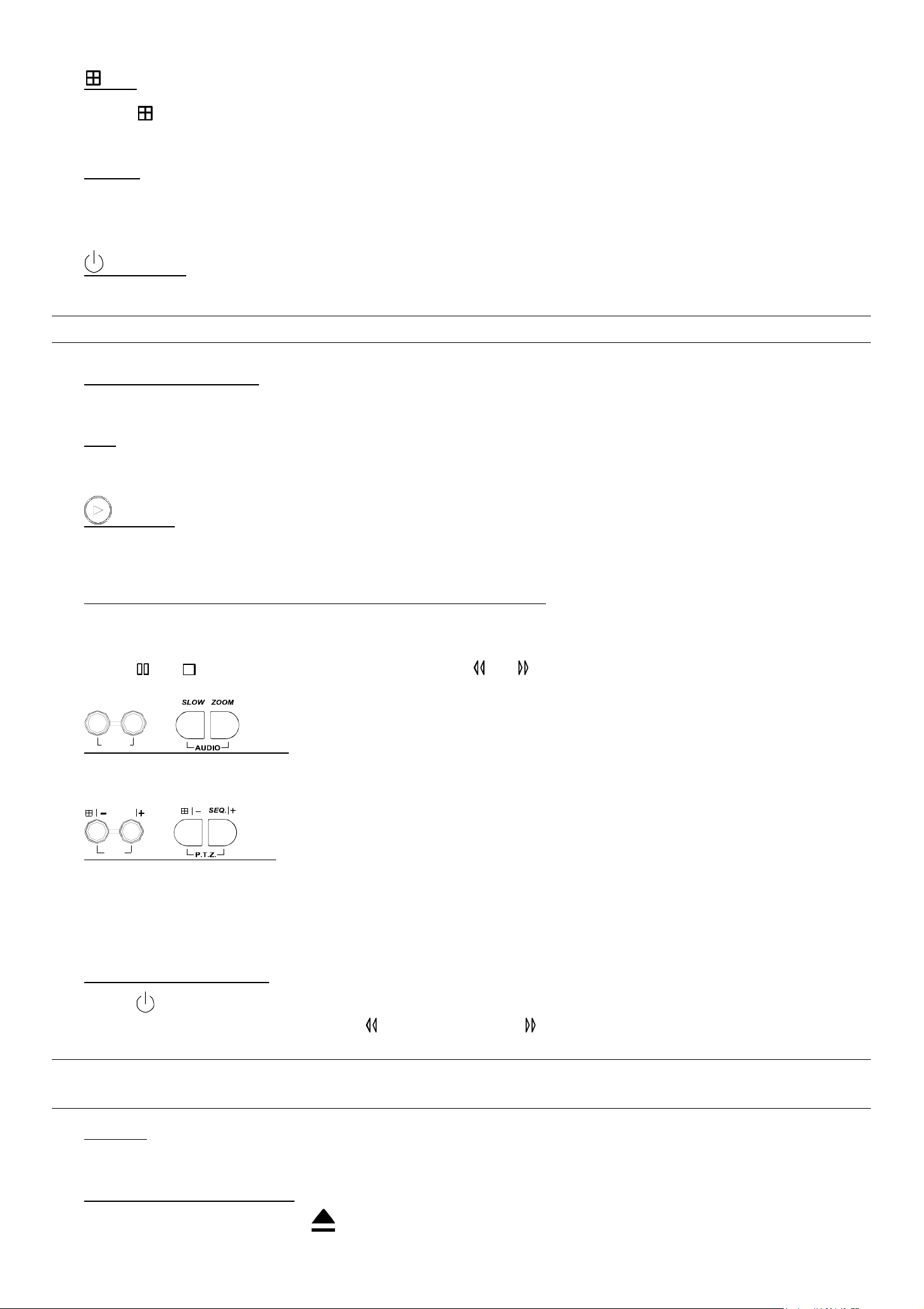
5) SLOW
Under the playback mode,
Model 1, 2 & 5: Press “SLOW” button to get 1/4X speed playback and press twice to get 1/8X speed playback.
Model 3 & 4: Press “SLOW” button to get 1/2X speed playback.
6) ZOOM
Press “ZOOM” button to enlarge the picture of selected channel (under the live mode).
-4-
FRONT AND REAR PANELS
7) / -
Press “ ” button to show the 4 channel display modes.
Press “-” button to change the setting in the menu.
8) SEQ /+
Press “SEQ” button to activate the call monitor function, and press again to quit.
Press ”+” button to change the setting in the menu.
9) or POWER
Press this button long enough to turn on/off your DVR.
Note: Under the recording mode, please stop recording before turning off your DVR.
10) “CH1” “CH2” “CH3” “CH4”
Press one of the buttons to select the channel to display.
11) REC
Press “REC” button to activate manual recording.
12) or PLAY
Press this button to play the recorded video.
13) UP / PAUSE, DOWN / STOP, LEFT / REWIND, RIGHT / FORWARD,
Press one of the direction buttons to move the cursor up/down/left/right.
Under the playback mode:
Press “ ” or “ ” button to pause / stop playback. Press “ ” or “ ” button to fast rewind / forward.
SLOW
ZOOM
14)
AUDIO
or (Audio)
Press these two buttons at the same time to select live or playback sounds of the audio channels.
SEQ.
15)
P.T.Z
or (PTZ)
Press these two buttons at the same time to enter / exit the PTZ control mode.
In the PTZ control mode → Zoom in: Press "+" button ; Zoom out: Press "-" button
Adjust PTZ angle: Press direction buttons to turn up/down/left/right
16) Switch NTSC / PAL System
Press “ ” or “POWER” button on the DVR front panel to shutdown the DVR.
After shutdown the DVR, press and hold (switch to NTSC) or (switch to PAL) first, then press the power button
again to reboot the DVR (press until the monitor shows video images).
Note: The DVR will automatically detect PAL/NTSC system. But you can also manually switch between PAL
and NTSC systems.
17) Key Lock
Press “MENU” + “ENTER” on the DVR front panel at the same time to lock keys and to log in with another user name.
18) Open / Close the the CD Writer
For Model 1 and Model 5, press “ ” buttons at the same time to open / close the CD Writer.
-5-
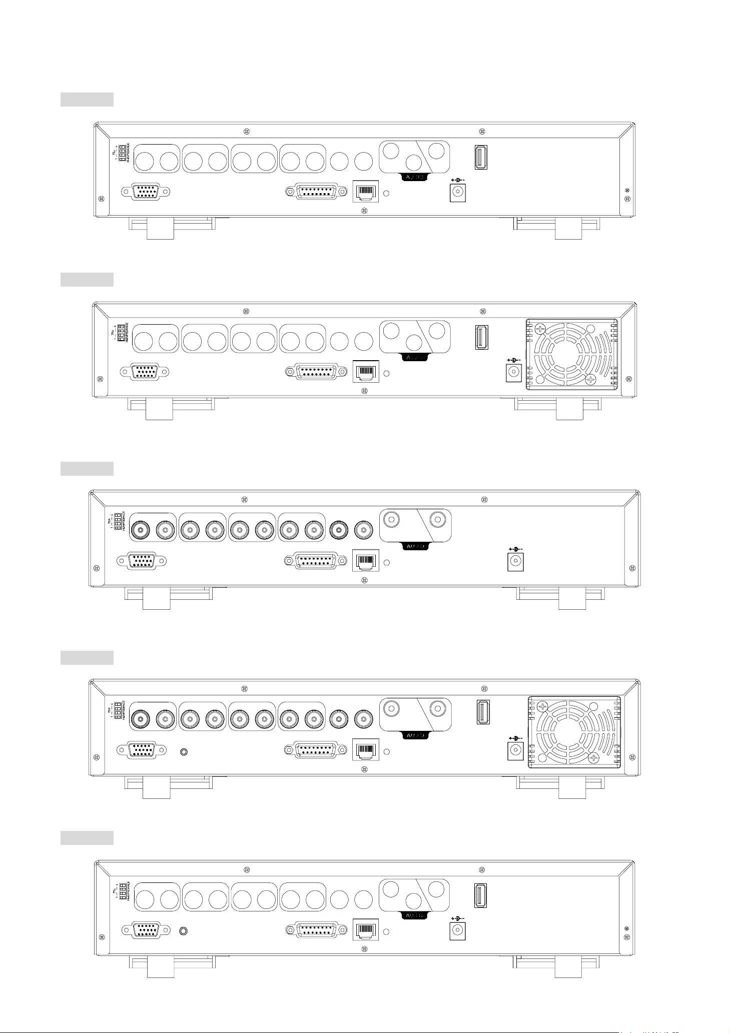
2.2 Rear Panels
‧ MODEL 1
FRONT AND REAR PANELS
‧ MODEL 2
LOOP
LOOP
INPUT
LOOP LOOP LOOP
INPUT
1
VD
/
2
INPUT
3
INPUT
4
EXT ERNA L I/O
CAL LMONIT OR
LAN
1
2
IN
LINK
ACT.
OUT
USB
DC 19V
INPUT
LOOP LOOP LOOP
INPUT
1
VD
/
2
INPUT
3
INPUT
4
EXTERNAL I/O
CAL LMONIT OR
LAN
1
IN
LINK
ACT.
OUT 2
USB
DC 19V
‧ MODEL 3
‧ MODEL 4
LOOP
LOOP
INP UT
1
VD
/
INPUT
LOOP LOOP LOOP
2
INP UT
3
INP UT
4
EXTERNAL I/O
CALLMONITOR
LAN
1
IN
LINK
ACT.
OUT
DC 19V
INP UT
1
VD
/
INPUT
LOOP LOOP LOOP
2
INP UT
3
INP UT
4
EXTERNAL I/OIR
CALLMONITOR
LAN
1
IN
LINK
ACT.
OUT
USB
DC 19V
‧ MODEL 5
LOOP
INPU T
LOOP LOOP LOO P
INPU T
1
VD
/
2
IR
INPUT
3
INPUT
4
EXTERNAL I/O
CAL LM ONITO R
LAN
1
2
IN
LINK
ACT.
OUT
USB
DC 19V
-6-

FRONT AND REAR PANELS
1) 75Ω / HI-IMPEDANCE
When using LOOP function, please switch to HI-IMPEDANCE. Otherwise, please switch to 75Ω.
2) LOOP / INPUT (For channel 1~4)
LOOP: Video output connector.
INPUT: Connect to video sources, such as cameras.
Note: If you want to playback the video with audio, please connect an audio camera to the correct channel.
Model 1, 2 & 5: Please connect audio cameras to INPUT1 and/or INPUT 2 on the DVR rear panel.
Model 3 & 4: Please connect audio camera to INPUT 1 on the DVR rear panel
3) MONITOR
Connect to MAIN monitor.
4) CALL
Connect to CALL monitor to show the channel display one by one.
When any alarm is triggered, CALL monitor will show the image of the triggered channel for a period of time.
5) Audio IN
Connect to audio sources, such as cameras equipped with the audio function.
When users start recording, the audio input will also be recorded.
6) Audio OUT
Connect to a monitor or speaker with 1 mono audio output.
7) USB (For MODEL 1, 2, 4 & 5)
Support USB flash drive firmware update and file backup.
Note: For the list of compatible USB flash drives, please refer to “APPENDIX 5 COMPATIBLE USB FLASH
DRIVE BRAND” at page 55.
8) D/V Port (Digital Video Port)
Connect to VGA connecter.
9) IR (For Model 4 & 5)
Connect the IR receiver for remote control.
10) EXTERNAL I/O
Insert the supplied 15PIN DSUB to this port for connecting external devices (external alarm, PTZ camera, etc).
For detailed I/O port PIN configuration, please refer to “APPENDIX 2 PIN CONFIGURATION” at page 51.
11) LAN
Connect to Internet by LAN cable.
12) LINK ACT.
When your DVR is connected to the Internet, this LED will be on.
13) DC 19V
Connect to the supplied adapter.
-7-

BASIC OPERATION
3. CONNECTIONS AND SETUP
3.1 Install HDD
The HDDs must be installed before the DVR is turned on. For detailed installation instructions, please refer to
section "APPENDIX 1 INSTALL HDD" at page 50.
3.2 Camera Connection
The cameras must be connected and power-supplied before the DVR is turned on. For detailed DVR video input /
output ports, please refer to section “2.2 Rear Panels” at page 6. For detailed external I/O port description, please refer to
section “APPENDIX 2 PIN CONFIGURATION” at page 51. For detailed camera setup, please refer to its own manual.
Note: When using LOOP function, set the impedance switch at your DVR rear panel to HI-IMPEDANCE to
decrease interferences. The default setting is 75Ω.
3.2.1 Normal Camera Connection
1) Connect the camera with indicated power supply.
2) Connect the camera video output to the DVR video input port with a coaxial cable and BNC connector.
For detailed camera title, ID, protocol and baud rate setup, please refer to section “6.4.5 Remote” at page 22.
3.2.2 PTZ Camera Connection
1) Connect the PTZ camera with indicated power supply.
2) Connect the PTZ camera video output to the DVR video input port with a coaxial cable and BNC connector.
3) For using DVR to control the PTZ camera, please connect the RS485-A line (brown) of the PTZ camera to the PIN11 of
the DVR DSUB solder side, and connect RS485-B line (orange) to the PIN10 of the DVR DSUB solder side.
And then solder them together in case of loosening.
Note: For detailed camera ID, protocol and baud rate setup at DVR side, please refer to section “6.4.5
Remote” at page 22. For detailed camera ID, protocol and baud rate setup at remote AP software side,
please refer to section “(1) Device” at page 39 (AP software system configuration). For detailed PTZ
control instructions, please refer to section “6.6.5 PTZ Camera Setup and Control” at page “30”.
3.3 External Device Connections
3.3.1 VGA Converter (Optional)
This optional peripheral (VGA Converter) allows your DVR to have VGA output function. Connect VGA CONNECTER
(A) to the MONITOR VGA CONNECTER (a), and connect VGA CONNECTER (B) to the DVR D/V PORT (b).
Please refer to the following figure as an example.
3.3.2 IR Transmitter
For MODEL 4 & MODEL 5 DVR, IR remote control is supported (Other models are optional). Please connect the IR
receiver line to the IR port on the DVR rear panel. And make sure the IR function is activated in the DVR menu (The
default setting is on). Please refer to the following figure as an example.
VGA
INPUT
LOOP
1
VD/
A: Connect to MonitorVideo Input
B: Connect to DVRVideo Output
1
INPUT2LOOP LOOP LOOP3INPUT4INP UT
D / V
CALLMONITOR
IN OUT
EXTERNAL I/OIR
LAN
USB
LINK
ACT.
DC 19V
B
A
MONITOR
-8-

BASIC OPERATION
3.4 DVR Power Setup
This device should be operated only with the type of power source indicated on the manufacturer’s label. Connect the
indicated AC power cord to the power adapter, and plug into an electrical outlet. “POWER” LED will be on as red. Press
“POWER” button, and “POWER” LED will be on as green. It takes approximately 10 to 15 seconds to boot the system.
3.5 Date and Time Setting
Before operating your DVR, please set the date and time on your DVR first.
You can use the following buttons for menu setting:
BUTTON FUNCTION
UP, DOWN, LEFT, RIGHT Move the cursor.
+ , -
ENTER Go to the submenu / confirm the selection.
MENU Go to the menu list / confirm the change / exit the menu list.
1) Date and System Time:
Choose numbers / selections.
The menu path is as following: “MENU” → “DATE”.
2) Daylight Saving:
The menu path is as following: “MENU” → “DATE” → “DAYLIGHT SAVING”. Take the following option as an example:
DAYLIGHT SAVING
START 4TH-SUN-MAR 24:00:00
END 4TH-SUN-OCT 24:00:00
ADJUST 01:00
Note: Please DO NOT change the date or time of your DVR after the recording function is
activated. Otherwise, the recorded data will be disordered and you will not be able to find the
recorded file to backup by time search. If users change the date or time accidentally when the
recording function is activated, it’s recommended to clear all HDD data, and start recording again.
3.6 LAN or Internet Setup
3.6.1 STATIC IP
1) Build a Local Area Network (LAN) between DVR and PC/NB with network cable:
Your NB/PC and DVR must be under the same network domain to build the area network. Please change the IP
address of your PC/NB into 192.168.1.X (X can be the number between 1~255, except 10) and the subnet mask into
255.255.255.0 for communicate with the DVR.
Note: Before changing the network properties of your PC/NB, please write down the original network
properties in case you need to recover the properties later.
Install the supplied AP software on your NB/PC. Then, log into the DVR with the supplied AP software for the
following default DVR settings.
‧ The DVR default IP address: 192.168.1.10
‧ The DVR default account / password: admin
‧ The DVR default port: 80
2) Set DVR network setting in “SYSTEM CONFIG” → “Network” of the supplied AP:
In the “SYSTEM CONFIG” → “Network” of the supplied AP, select the “Static IP” in “IP TYPE” section. And then
type the “Server IP”, “Gateway”, “Net Mask” and “Web Port” (1~9999) information obtained from your ISP.
Press ”APPLY” button to confirm the setting.
3) Login your DVR via an Ethernet or dial-up network.:
After setting up the network information of the DVR and connect it to the network, you can use the IP address / Port
/ Account / Password you just entered in the supplied AP software to log into your DVR remotely.
-9-

BASIC OPERATION
3.6.2 DDNS Apply
You need to apply a DDNS account before setting PPPoE or DHCP connection. DDNS is a service for transforming
the dynamic IP corresponding to a specific “Hostname”. For DDNS setup, please refer to the steps below.
‧ Go to a website which provides free DDNS services and apply a “Hostname”.
For example, go to http://www.dyndns.com.
‧ Enter all the information necessary for signing up an account according to the website instructions.
‧ Then, you will see the screen “Account Created”, and Dyndns will email the instructions to your specified E-mail
address for enabling your account. You must complete the procedure according to the instructions in the mail. That is
to must visit the confirmation address within 48 hours of the time that the e-mail was sent to complete the account
creation process. Then, you will see “Account Confirmed”. Your account is created successfully now.
‧ Log in with your account information and click ”My Service”.
‧ Click ”Add Host Services”.
‧ Click ”Add Dynamic DNS Host”.
‧ Fill in and choose the desired host name.
‧ The host name is created. You will be connected to the corresponding IP address whenever you enter this hostname.
3.6.3 Dynamic IP - PPPOE
1) Build a Local Area Network (LAN) between DVR and PC/NB with network cable:
Your NB/PC and DVR must be under the same network domain to build the area network. Please change the IP
address of your PC/NB into 192.168.1.X (X can be the number between 1~255, except 10) and the subnet mask into
255.255.255.0 for communicate with the DVR.
Install the supplied AP software on your NB/PC. And then login the DVR with the supplied AP software for the
following default DVR settings.
‧ The DVR default IP address: 192.168.1.10
‧ The DVR default account / password: admin
‧ The DVR default port: 80
2) Set DVR network setting in “SYSTEM CONFIG” → “Network” of the supplied AP:
In the “SYSTEM CONFIG” → “Network” of the supplied AP, select the “PPPOE” in “IP TYPE” section. And then
type the “User Name” and “Password” obtained from your ISP. Press ”APPLY” button to confirm the setting.
3) Set DVR DDNS setting in the “SYSTEM CONFIG” → “DDNS” of the supplied AP software:
‧ DDNS: Choose “Enable”.
‧ User Name: Type your DDNS account.
‧ Password: Type your DDNS password.
‧ Domain: Type the “Host Name” you applied previously (EX: securityanytime.dyndns.org).
‧ System Name: Choose the DDNS server where you applied the domain name (EX: dyndns).
‧ After setting, please press “APPLY” button to confirm and finish the setting.
4) Login your DVR via an Ethernet or dial-up network.:
After setting up the network information of the DVR and connect it to the network, you can type DDNS host name,
default user name and password in the supplied AP software login page to log into your DVR remotely.
-10-

BASIC OPERATION
3.6.4 Dynamic IP - DHCP
Get a router and use the default IP address provided by your router to login to the router. Enable the DHCP server
and set the starting IP address, ending IP address and lease time. The DHCP Server of the router will automatically
allocate an unused IP address from the IP address pool to the requesting computer.
1) Build a Local Area Network (LAN) between DVR and PC/NB with network cable:
Your NB/PC and DVR must be under the same network domain to build the area network. Please change the IP
address of your PC/NB into 192.168.1.X (X can be the number between 1~255, except 10) and the subnet mask into
255.255.255.0 for communicate with the DVR.
Install the supplied AP software on your NB/PC. And then login the DVR with the supplied AP software for the
following default DVR settings.
‧ The DVR default IP address: 192.168.1.10
‧ The DVR default account / password: admin
‧ The DVR default port: 80
2) Set DVR network setting in “SYSTEM CONFIG” → “Network” of the supplied AP:
In the “SYSTEM CONFIG” → “Network” of the supplied AP, select the “DHCP” in “IP TYPE” section. Then
press ”APPLY” button to confirm the setting.
Set DVR DDNS setting in the “SYSTEM CONFIG” → “DDNS” of the supplied AP software.
‧ DDNS: Choose “Enable”.
‧ User Name: Type your DDNS account.
‧ Password: Type your DDNS password.
‧ Domain: Type the “Host Name” you applied previously (EX: securityanytime.dyndns.org).
‧ System Name: Choose the DDNS server where you applied the domain name (EX: dyndns).
‧ After setting, please press “APPLY” button to confirm and finish the setting.
3) Login your DVR via an Ethernet or dial-up network:
After setting up the network information of the DVR and connect it to the network, you can type DDNS host name
and default user name and password in the supplied AP software login page to log into your DVR remotely.
-11-
3.7 Password and User Name Setting
3.7.1 DVR Password Setting
The menu path is as following: MENU → ADVANCE → SYSTEM → PASSWORD → SETUP → ADMIN
PASSWORD / GUEST PASSWORD. You can use the following buttons for menu setting:
BUTTON FUNCTION
UP, DOWN, LEFT, RIGHT Move the cursor.
+ , -
ENTER Go to the submenu / confirm the selection.
MENU Go to the menu list / confirm the change / exit the menu list.
1) Admin password:
Password for supervisor, allow all the setup of DVR.
Choose numbers / selections.
BASIC OPERATION
2) Guest password:
Only allow viewing the live streaming video and sequencing display, shifting the channel display, and locking keys.
3.7.2 Remote Login Password and User Name Setting
In the “SYSTEM CONFIG” → “Account” of the supplied AP software, you can set up user accounts (max. 5
accounts), password, life time, and authority level (max. 5 users on line at the same time) for remote login to the DVR. For
detailed instructions, please refer to “(1) Account” in the section “7.5.4 General” at page 46.
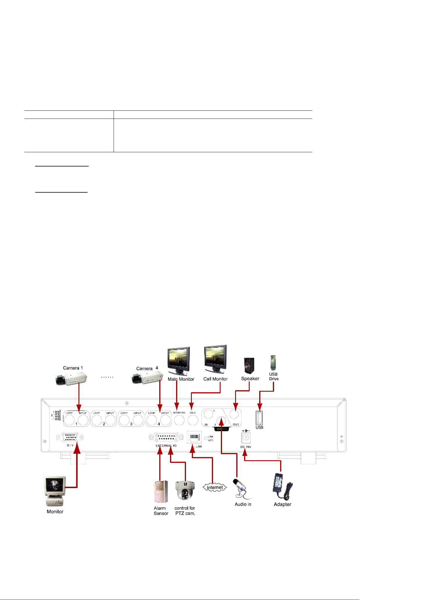
3.8 System Diagram
After you finish all the connections, a surveillance system is established and you can experience the marvelous and
useful functions of this DVR. The diagram below illustrates all the available connections of this DVR for you to picture your
surveillance system (Take Model 1 as an example).
-12-

BASIC OPERATION
4. BASIC OPERATION
4.1 Recording
This device offers three recording modes: manual record, event record and timer record. If the power is off
accidentally, the recorded video data will not be lost and is safely stored in the HDD. The device will return to the original
recording status after the power is on again.
‧ MANUAL RECORD (continuous recording)
Recording is initiated by manually pressing “REC” button on the front panel.
This mode is indicated by the sign “z” on the screen.
‧ EVENT RECORD (triggered by motion and external alarm)
When this function is activated, the recording is triggered by motion or external alarms.
This mode is indicated by the sign " " (motion) or " " (external alarm) on the screen.
‧ TIMER RECORD (scheduled time)
Recording is scheduled by TIMER function.
Indicated by the wording “TIMER RECORD” on the monitor.
Note: When the recording function is activated, please DO NOT change the date or time on your DVR. The recorded
data will be disordered and you will not be able to find the recorded data to backup by time search.
If users change the date or time accidentally when the recording function is activated, please clear all HDD data,
and start recording again.
Overwriting Mode
If the overwriting mode is enabled, you will see “-OW-” (1) under the recording mode except the system time (2),
available HDD capacity (3), recording icon (4) and channel title (5).
When the HDD is full under “-OW-” recording mode, the previous recorded data will be overwritten without notice.
Under “-OW-" mode, this device will clear 8GB data from the oldest for continuous recording once the HDD is full.
To turn on/off this mode, please refer to the section “6.4.6 System” at page 22.
-13-

BASIC OPERATION
4.2 Playback
Press “ ” or “PLAY” button on the front panel, and the device will display the last recorded video.
Note: There must be at least 8192 images of recorded data for playback to work properly. If not, the device
will stop playback. For example, if the IPS is set to 30, the recording time should be at least 273
seconds (8192 images / 30 IPS) for the playback to work properly.
Playback related operations are described below:
‧ Fast Forward ( ) / Fast Rewind ( )
You can increase the speed for fast forward and rewind on this device. In the playback mode:
Press “ “ once to get 4X speed forward and press twice to get 8X speed, etc. And the maximum speed is 32X.
Press “ “ once to get 4X speed rewind and press twice to get 8X speed, etc. And the maximum speed is 32X.
‧ Pause ( ) / Image Jog
Press “ “ button to pause the video playback.
In the Pause mode:
Press “ “ button once to get one frame forward.
Press “ “ button once to get one frame rewind.
‧ Stop ( )
Pressing “ ” button under all circumstances will return this device to live monitoring mode.
‧ Channel Display Mode
Display mode:
Press “ ” button to show the 4 channel display modes.
Full screen view:
Press one of the number buttons from 1-4 to show the selected channel in the full screen.
Under the playback mode, you can select a channel to display the live video instead of the playback video.
For details, please refer to “Position of Channel Display” in section ”2.1 Front Panels” at page 4.
‧ Slow Playback
Model 1, 2 & 5: Press “SLOW” button to get 1/4X speed playback and press twice to get 1/8X speed playback.
Model 3 & 4: Press “SLOW” button to get 1/2X speed playback.
‧ Audio
SLOW
ZOOM
Press
AUDIO
or buttons at the same time to select to play either live (L) or playback (P) sound.
AUDIO 1 (L) – 1st audio channel, live audio;
AUDIO 1 (P) – 1st audio channel, playback audio
AUDIO 2 (L) – 2nd audio channel, live audio (Only Model 1, 2 & 5 have AUDIO 2 option)
AUDIO 2 (P) – 2nd audio channel, playback audio (Only Model 1, 2 & 5 have AUDIO 2 option)
Note: If you want to playback the video with audio, please connect an audio camera to the correct channel.
Model 1, 2 & 5: Please connect audio cameras to INPUT1 and/or INPUT 2 on the DVR rear panel.
Model 3 & 4: Please connect audio camera to INPUT 1 on the DVR rear panel.
-14-
 Loading...