

Page 1
205
USER’S MANUAL
Please read instructions thoroughly before operation and retain it for future reference.
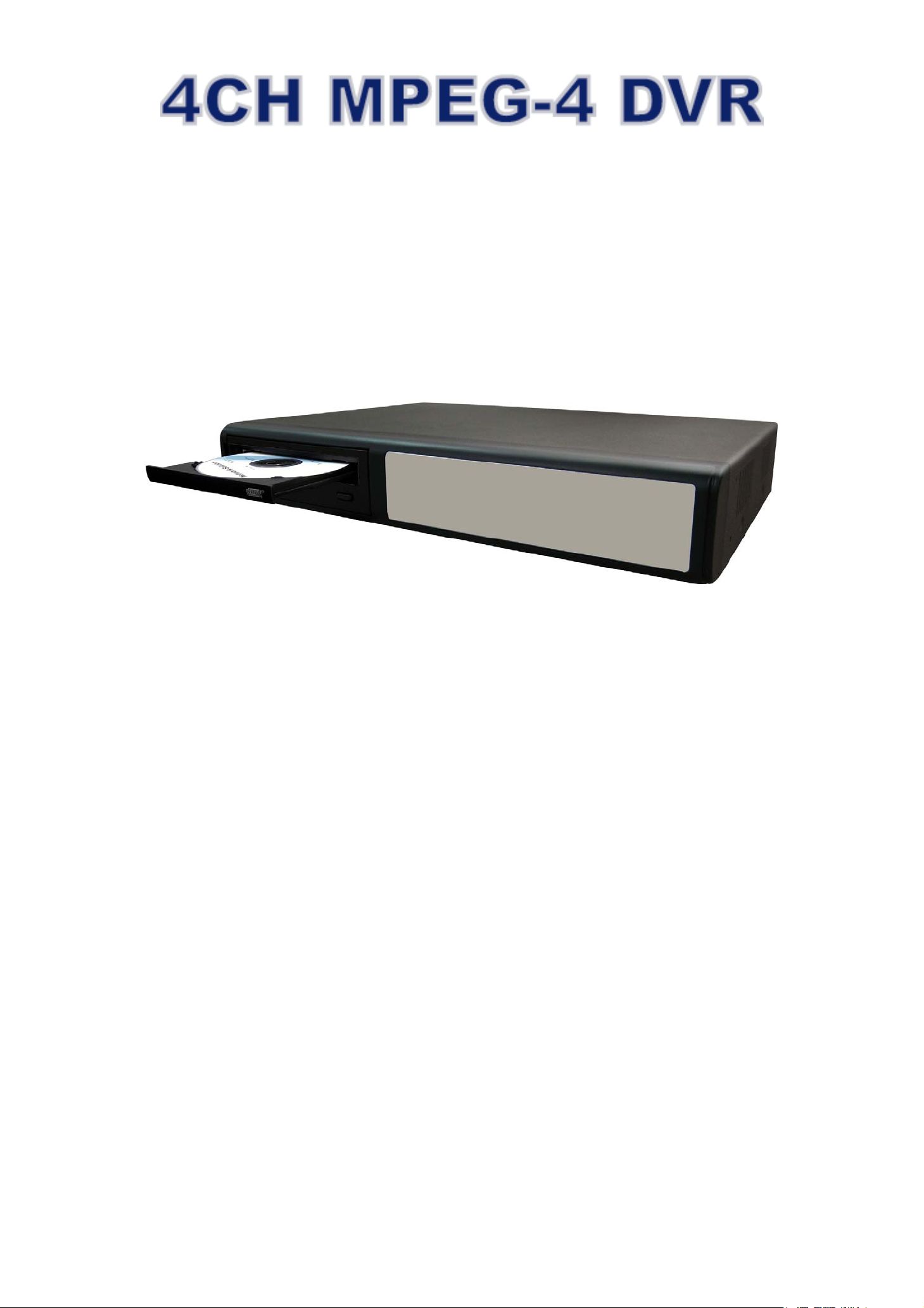
The image shown above may differ from the actual product appearance.
ENGLISH 782, 781, 760, 761, 782A / 502, 501, 560, 561, 502A_V1.4
Page 2
IMPORTANT SAFEGUARD
CAUTION:
To reduce the risk of electric shock, do not expose this apparatus to rain or moisture.
Only operate this apparatus from the type of power source indicated on the label.
The company shall not be liable for any damages arising out of any improper use,
even if we have been advised of the possibility of such damages.
Graphic Symbol Explanation
The lightning flash with arrowhead symbol, within an equilateral triangle, is intended to alert the user to the
presence of uninsulated “dangerous voltage” within the product’s enclosure that may be of sufficient
CCAAUUTTIIOONN
RRIISSKK OOFF EELLEECCTTRRIICC SSHHOOCCKK
magnitude to constitute a risk of electric shock to persons.
This exclamation point within an equilateral triangle is intended to alert the user to the presence of important
operating and maintenance (servicing) instructions in the literature accompanying the appliance.
CE Mark
This apparatus is manufactured to comply with the radio interference requirements.
Disclaimer
We reserve the right to revise or remove any content in this manual at any time. We do not warrant or assume any legal
liability or responsibility for the accuracy, completeness, or usefulness of this manual. The content of this manual is subject
to change without notice.
MPEG4 Licensing
THIS PRODUCT IS LICENSED UNDER THE MPEG-4 VISUAL PATENT PORTFOLIO LICENSE FOR THE PERSONAL
AND NON-COMMERCIAL USE OF A CONSUMER FOR (i) ENCODING VIDEO IN COMPLIANCE WITH THE MPEG-4
VISUAL STANDARD (“MPEG-4 VIDEO”) AND/OR (ii) DECODING MPEG-4 VIDEO THAT WAS ENCODED BY A
CONSUMER ENGAGED IN A PERSONAL AND NON-COMMERCIAL ACTIVITY AND/OR WAS OBTAINED FROM A
VIDEO PROVIDER LICENSED BY MPEG LA TO PROVIDE MPEG-4 VIDEO. NO LICENSE IS GRANTED OR SHALL BE
IMPLIED FOR ANY OTHER USE. ADDITIONAL INFORMATION INCLUDING THAT RELATING TO PROMOTIONAL
INTERNAL AND COMMERCIAL USES AND LICENSING MAY BE OBTAINED FROM MPEG LA, LLC. SEE
HTTP://WWW.MPEGLA.COM.
Version
Firmware Version: 1098-10-K2-04-AA-11 ; AP Version: 1062
For any changes of AP, please refer to your distributor. The content is this manual is subject to change without notice.
Page 3

TABLE OF CONTENTS
1. OVERVIEW .......................................................................................................................................... 1
1.1 Product Description.................................................................................................................................................1
1.2 Features..................................................................................................................................................................1
1.3 Specification............................................................................................................................................................2
1.4 Package Contents...................................................................................................................................................3
2. FRONT AND REAR PANELS .............................................................................................................. 4
2.1 Front Panels............................................................................................................................................................4
2.2 Rear Panels ............................................................................................................................................................6
3. CONNECTIONS AND SETUP.............................................................................................................. 8
3.1 Install HDD..............................................................................................................................................................8
3.2 Camera Connection ................................................................................................................................................8
3.2.1 Normal Camera Connection .........................................................................................................................8
3.2.2 PTZ Camera Connection ..............................................................................................................................8
3.3 External Device Connections..................................................................................................................................8
3.3.1 VGA Converter (Optional) .............................................................................................................................8
3.3.2 IR Transmitter ...............................................................................................................................................8
3.4 DVR Power Setup...................................................................................................................................................9
3.5 Date and Time Setting ............................................................................................................................................9
3.6 LAN or Internet Setup .............................................................................................................................................9
3.6.1 STATIC IP .....................................................................................................................................................9
3.6.2 DDNS Apply................................................................................................................................................10
3.6.3 Dynamic IP - PPPOE ..............................................................................................................................10
3.6.4 Dynamic IP - DHCP ................................................................................................................................11
3.7 Password and User Name Setting ........................................................................................................................12
3.7.1 DVR Password Setting ...............................................................................................................................12
3.7.2 Remote Login Password and User Name Setting.......................................................................................12
3.8 System Diagram ...................................................................................................................................................12
4. BASIC OPERATION .......................................................................................................................... 13
4.1 Recording .............................................................................................................................................................13
4.2 Playback ...............................................................................................................................................................14
5. MAIN MENU....................................................................................................................................... 15
5.1 Menu Tree.............................................................................................................................................................15
6. MENU FUNCTION.............................................................................................................................. 16
6.1 Record ..................................................................................................................................................................16
6.2 Timer.....................................................................................................................................................................17
6.3 Date ......................................................................................................................................................................17
6.4 Advance ................................................................................................................................................................18
6.4.1 Camera .......................................................................................................................................................18
6.4.2 Detection.....................................................................................................................................................18
(1) Detection Setup.......................................................................................................................................19
(2) Detection Timer .......................................................................................................................................20
6.4.3 Display ........................................................................................................................................................20
6.4.4 Alert ............................................................................................................................................................21
6.4.5 Remote .......................................................................................................................................................22
6.4.6 System........................................................................................................................................................22
6.4.7 Network.......................................................................................................................................................24
6.4.8 Backup........................................................................................................................................................25
6.4.9 HDD Info .....................................................................................................................................................27
6.4.10 Event Log..................................................................................................................................................27
Page 4

6.5 Search ..................................................................................................................................................................28
6.6 Additional Operation..............................................................................................................................................29
6.6.1 Key Lock and Unlock ..................................................................................................................................29
6.6.2 Switch NTSC / PAL System ........................................................................................................................29
6.6.3 Upgrade ......................................................................................................................................................29
(1) Firmware / Multilanguage OSD Upgrade.................................................................................................29
(2) AP and JAVA Software Upgrade..............................................................................................................29
6.6.4 Audio Backup and Playback .......................................................................................................................29
6.6.5 PTZ Camera Setup and Control .................................................................................................................30
6.6.6 R.E.T.R. Setup (For Model 5 only) ..............................................................................................................30
7. LICENSED SOFTWARE AP .............................................................................................................. 31
7.1 Installation.............................................................................................................................................................31
7.2 Login Panel...........................................................................................................................................................31
7.3 Control Panel ........................................................................................................................................................32
7.3.1 DVR Control Panel .....................................................................................................................................32
7.3.2 PTZ Camera Control Panel.........................................................................................................................34
7.4 Playback Operation...............................................................................................................................................35
7.4.1 AP Playback Functions: ..............................................................................................................................35
7.4.2 Convert the recorded file to AVI format .......................................................................................................36
7.5 System Configuration............................................................................................................................................36
7.5.1 Network.......................................................................................................................................................36
(1) DDNS ......................................................................................................................................................37
(2) Mail..........................................................................................................................................................38
(3) FTP .........................................................................................................................................................38
7.5.2 DVR ............................................................................................................................................................39
(1) Device .....................................................................................................................................................39
(2) Detection .................................................................................................................................................40
(3) Network Backup ......................................................................................................................................40
(4) Search List ..............................................................................................................................................42
(5) Timer Record...........................................................................................................................................43
(6) Date.........................................................................................................................................................43
(7) Record Setting ........................................................................................................................................44
7.5.3 Alarm...........................................................................................................................................................44
(1) Alarm List (For Model 5 Only)..................................................................................................................45
7.5.4 General.......................................................................................................................................................46
(1) Account ...................................................................................................................................................46
(2) Online User Info ......................................................................................................................................47
(3) File Path ..................................................................................................................................................47
7.6 Operation via IE Browser ......................................................................................................................................48
8. TROUBLESHOOTING ....................................................................................................................... 49
8.1 FAQ.......................................................................................................................................................................49
8.2 Default Value.........................................................................................................................................................49
APPENDIX 1 INSTALL HDD.................................................................................................................. 50
APPENDIX 2 PIN CONFIGURATION ....................................................................................................51
APPENDIX 3 RS-232 PROTOCOL........................................................................................................ 52
APPENDIX 4 RECORDING TIME TABLE ............................................................................................. 53
APPENDIX 5 COMPATIBLE USB FLASH DRIVE BRAND................................................................... 55
APPENDIX 6 COMPATIBLE HDD BRAND ........................................................................................... 56
Page 5

1. OVERVIEW
1.1 Product Description
ITEMS Model 1 Model 2 Model 3 Model 4 Model 5
Video Compression
Format
USB Interface YES YES NO YES YES
Backup Device Support USB 1.1/ 2.0
IR Transmitter NO NO NO YES YES
Audio I/O 2 audio inputs,
R.E.T.R. (Remote Event
Trigger Recording)
Dimension 375mm (W) × 61mm
Frame: MPEG 4 ;
CIF: MPEG4
flash drive, CD writer
and network remote
backup
1 audio output (Mono)
NO NO NO NO YES
(H) × 281mm (D)
Frame: MPEG 4 ;
CIF: MPEG4
Support USB 1.1/ 2.0
flash drive and network
remote backup
2 audio inputs,
1 audio output (Mono)
343mm (W) × 59mm
(H) × 223mm (D)
Frame: MJPEG ;
CIF: MPEG4
Network remote
backup
1 audio input,
1 audio output (Mono)
343mm (W) × 59mm
(H) × 223mm (D)
Frame: MJPEG ;
CIF: MPEG4
Support USB 1.1/ 2.0
flash drive and network
remote backup
1 audio input,
1 audio output (Mono)
345mm (W) x 68.3mm
(H) x 225mm (D)
Frame: MPEG 4 ;
CIF: MPEG4
Support USB 1.1/ 2.0
flash drive, CD writer
and network remote
backup
2 audio inputs,
1 audio output (Mono)
375mm (W) × 61mm
(H) × 281mm (D)
1.2 Features
MPEG4 DVR Technology
‧ Compression format providing crystal clear images with real time performance
Multiplex Operation
‧ Allow live display, record, playback, backup, and network operations at the same time
Free Upgrade to Advanced Functions
‧ Allow you to upgrade DVR functions without any charges
Long-Recording Hours
‧ Model 1 & 2 & 5: 500GB can record more than 18 days. (4CH, Frame Best Quality, 30IPS)
‧ Model 3 & 4: 500GB can record more than 5 days. (4CH, Frame Best Quality, 30IPS)
Backup Function
‧ For model 1 & 5, support CD writer, USB flash drives and network remote recording & backup
‧ For model 2 & 4, support image backup with USB flash drives and net work remote recording & backup
‧ For model 3, support network remote recording & backup
Remote Surveillance
‧ Support remote surveillance up to 5 users simultaneously with licensed software AP and IE browser
Intelligent Motion Trigger Recording
‧ R.E.T.R. (Remote Event Trigger Recording) (This function is only for Model 5)
‧ With the advanced functions of motion detection, scheduled motion detection recording (4 different adjustable factors
for motion detection sensitivity) and quick search, customized security environments are achieved
‧ Alarm trigger recording will send alerts with images to designated e-mails and the FTP address
‧ Support pre-alarm recording (8MB)
Covert Recording
‧ A mask replaces the live image with a blank screen and the monitor shows nothing, but the recording is still on
A/V Support
‧
Support 2 audio-in, 1 audio-out to record sounds (Model 1, Model 2 and Model 5)
Support 1 audio-in, 1 audio-out to record sounds (Model 3 and Model 4)
-1-
Page 6

‧ Support VGA output to monitor (optional)
General
‧ Support multi-language OSD
‧ Model 4 & 5 support IR remote control (Other models are optional)
‧ System auto recovery after power reconnected
‧ Support PTZ camera operations through RS-485 signals
‧ Support daylight saving function
‧ Support manual / timer / motion / alarm / network remote recording
‧ Ensure the authentication of recorded images with Watermark function
‧ Support TCP/IP, PPPoE, DHCP and DDNS network connection
1.3 Specification
SPECIFICATION* Model 1 Model 2 Model 3 Model 4 Model 5
Video System
Video Compression Format
Video Input
Video Loop Out
Video Output
Maximum Recording Rate
Adjustable Recording Speed
Multi-language OSD
Image Quality Setting
Hard Disk Storage
HDD Quick Cleaning
NTSC / PAL (switchable)
Frame: MPEG 4 ;
Frame: MPEG 4 ; CIF: MPEG4 Frame: MJPEG ; CIF: MPEG4
CIF: MPEG4
4 Channels. Composite video signal 1 Vp-p 75Ω BNC
4 Channels. Composite video signal 1 Vp-p 75Ω BNC
Main Monitor Output: Composite video signal 1 Vp-p 75Ω BNC
Call Monitor Output: Composite video signal 1 Vp-p 75Ω BNC
Frame: 720 × 480 pixels with 30 IPS〈NTSC〉/ 720 × 576 pixels with 25 IPS〈PAL 〉
CIF: 352 × 240 pixels with 120 IPS〈NTSC〉/ 352 × 288 pixels with 100 IPS〈PAL 〉
Frame: 30, 15, 7, 3 IPS〈NTSC〉/ 25, 12, 6, 3 IPS〈PAL〉
CIF: 120, 60, 30, 15 IPS〈NTSC〉/ 100, 50, 25, 12 IPS〈PAL〉
YES
Best, High, Normal, and Basic
Accommodate 1 HDD (IDE type, ATA66), support HDD capacity over 500GB
* HDD is optional.
Quick clean up the “index system” of the recorded files. 500GB under 2 seconds
Recording Mode
Watermark
Refresh Rate
Audio I/O
R.E.T.R. (Remote Event Trigger Recording)
Motion Detection Area
Motion Detection Sensitivity
Pre-alarm Recording
USB Interface
Backup Device
Manual/Timer/Motion/Alarm /Remote
YES
120 IPS for NTSC / 100 IPS for PAL
2 audio inputs,
1 audio output (Mono)
NO YES
16 × 12 grids per camera for all channels
4 adjustable variables with precise calculation for motion detection
YES (8MB)
Support USB 1.1/ 2.0 flash drive NO Support USB 1.1/ 2.0 flash drive
Support USB 1.1/
2.0 flash drive,
CD writer and
network remote
backup
Support USB 1.1/
2.0 flash drive and
network remote
backup
Network remote
1 audio input,
1 audio output (Mono)
Support USB 1.1/
2.0 flash drive
backup
and network
remote backup
2 audio inputs,
1 audio output
(Mono)
Support USB 1.1/
2.0 flash drive,
CD writer and
network remote
backup
Web Transmitting Compression Format
Ethernet
*
The specifications are subject to change without notice.
Motion JPEG
10/100 Base-T. Support remote control and live view via Ethernet
-2-
Page 7
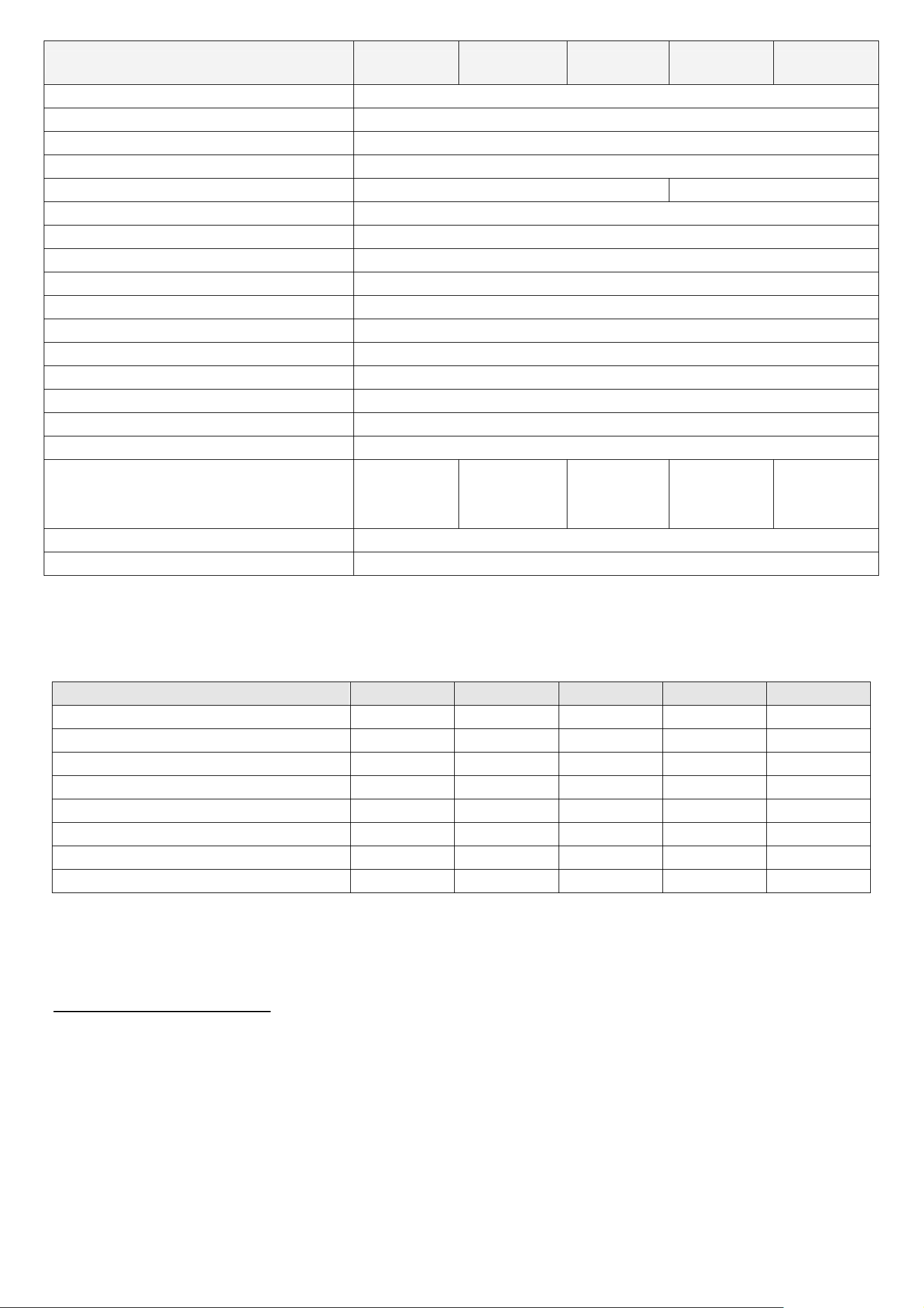
SPECIFICATION* Model 1 Model 2 Model 3 Model 4 Model 5
Web Interface
Remote Alarm Notification
Network Connection
PTZ control
IR Transmitter
Dwell Time (Sequential Channel Switch)
Alarm I/O
Digital Zoom
Key Lock
Video Loss Detection
Camera Title
Video Adjustable
Date Display Format
Power Source
Power Consumption
Operating Temperature
Support licensed software AP and IE browser
E-mail images, and upload images to FTP site’s specific account
Support TCP/IP, PPPOE, DHCP and DDNS functions
Support PELCO-D protocol
Optional YES
Programmable with adjustable dwell time (2, 4, 8, 16 sec.)
4 inputs, 1 output
2X digital zoom (live mode)
YES
YES
Support up to 6 letters
Hue/Color/Contrast/ Brightness
YY/MM/DD, DD/MM/YY, MM/DD/YY, and Off
DC 19V
<42 W
10℃ ~ 40℃ (50℉~104℉)
Dimensions (mm)
System Recovery
Optional Peripheral
375mm (W) ×
61mm (H) ×
281mm (D)
343mm (W) ×
59mm (H) ×
223mm (D)
System auto recovery after power reconnected
343mm (W) ×
59mm (H) ×
223mm (D)
VGA converter
345mm (W) x
68.3mm (H) x
225mm (D)
375mm (W) ×
61mm (H) ×
281mm (D)
1.4 Package Contents
ITEMS Model 1 Model 2 Model 3 Model 4 Model 5
Digital Video Recorder (DVR)
Adapter and Power Cord
CD Manual & Hard Copy Quick Start
Free Licensed Software AP Disc
Free Compact Disc (CD)
Screws * 4
ˇ ˇ ˇ ˇ ˇ
ˇ ˇ ˇ ˇ ˇ
ˇ ˇ ˇ ˇ ˇ
ˇ ˇ ˇ ˇ ˇ
ˇ
- - -
ˇ ˇ ˇ ˇ ˇ
ˇ
DSUB PIN Connector
ˇ ˇ ˇ ˇ ˇ
IR Receiver & Transmitter - - -
*
The specifications are subject to change without notice.
ˇ ˇ
-3-
Page 8

2. FRONT AND REAR PANELS
2.1 Front Panels
1) LED Indication
The following LEDs will be on when:
HDD: HDD is reading or recording
HDD Full: HDD is full.
ALARM: Once the alarm is triggered
TIMER: When timer recording is turned on
PLAY: Under playing status
REC: Under recording status
2) MENU
FRONT AND REAR PANELS
Press “MENU” button to enter the main menu.
3) ENTER / SET
‧ Press “ENTER” button to confirm the setting.
Press “SET” to change the position of the channel display.
Press up/down/left/right direction buttons to select the channel that you want to change.
Press “+“ or “-“ to select the channel which You would like to show.
‧ Channel Display Position
Under the live mode, you can switch the positions of two channels in the following way:
Step1: Press “Set” to highlight one channel.
Step2: Press “UP“, “DOWN”, “LEFT”, “RIGHT” button to move the highlight to the
channel you want to change its position.
Step3: Press “+” or “-” to select the channel you want to switch its position with the
one selected in Step2.
Step4: Press “ENTER” button to confirm the setting. For example, the position of CH2
& CH4 is switched as shown on the right side.
01
03
Under Live Mode
04
02
Under the playback mode, you can select a channel to display the live video instead of the playback video:
Step1: Press “Set” to highlight one channel.
Step2: Press “UP“, “DOWN”, “LEFT”, “RIGHT” button to move the highlight to the
01
04
channel you want to view the live video.
03 04
Step3: Press “+” or “-” to select the channel you want to view its live video.
Under Playback Mode
Step4: Press “ENTER” button to confirm the setting. For example, CH2 playback view
is replaced with CH4 live view as shown on the right side.
4) SEARCH
Press “SEARCH” button to enter the search menu.
5) SLOW
Under the playback mode,
Model 1, 2 & 5: Press “SLOW” button to get 1/4X speed playback and press twice to get 1/8X speed playback.
Model 3 & 4: Press “SLOW” button to get 1/2X speed playback.
6) ZOOM
Press “ZOOM” button to enlarge the picture of selected channel (under the live mode).
-4-
Page 9
FRONT AND REAR PANELS
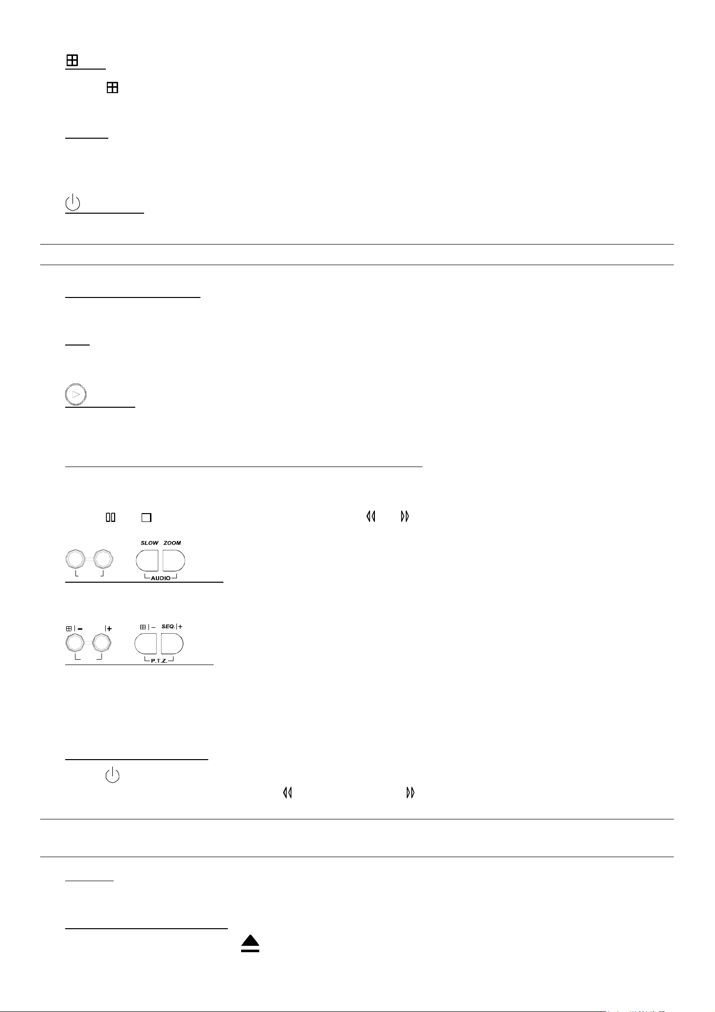
7) / -
Press “ ” button to show the 4 channel display modes.
Press “-” button to change the setting in the menu.
8) SEQ /+
Press “SEQ” button to activate the call monitor function, and press again to quit.
Press ”+” button to change the setting in the menu.
9) or POWER
Press this button long enough to turn on/off your DVR.
Note: Under the recording mode, please stop recording before turning off your DVR.
10) “CH1” “CH2” “CH3” “CH4”
Press one of the buttons to select the channel to display.
11) REC
Press “REC” button to activate manual recording.
12) or PLAY
Press this button to play the recorded video.
13) UP / PAUSE, DOWN / STOP, LEFT / REWIND, RIGHT / FORWARD,
Press one of the direction buttons to move the cursor up/down/left/right.
Under the playback mode:
Press “ ” or “ ” button to pause / stop playback. Press “ ” or “ ” button to fast rewind / forward.
SLOW
ZOOM
14)
AUDIO
or (Audio)
Press these two buttons at the same time to select live or playback sounds of the audio channels.
SEQ.
15)
P.T.Z
or (PTZ)
Press these two buttons at the same time to enter / exit the PTZ control mode.
In the PTZ control mode → Zoom in: Press "+" button ; Zoom out: Press "-" button
Adjust PTZ angle: Press direction buttons to turn up/down/left/right
16) Switch NTSC / PAL System
Press “ ” or “POWER” button on the DVR front panel to shutdown the DVR.
After shutdown the DVR, press and hold (switch to NTSC) or (switch to PAL) first, then press the power button
again to reboot the DVR (press until the monitor shows video images).
Note: The DVR will automatically detect PAL/NTSC system. But you can also manually switch between PAL
and NTSC systems.
17) Key Lock
Press “MENU” + “ENTER” on the DVR front panel at the same time to lock keys and to log in with another user name.
18) Open / Close the the CD Writer
For Model 1 and Model 5, press “ ” buttons at the same time to open / close the CD Writer.
-5-
Page 10
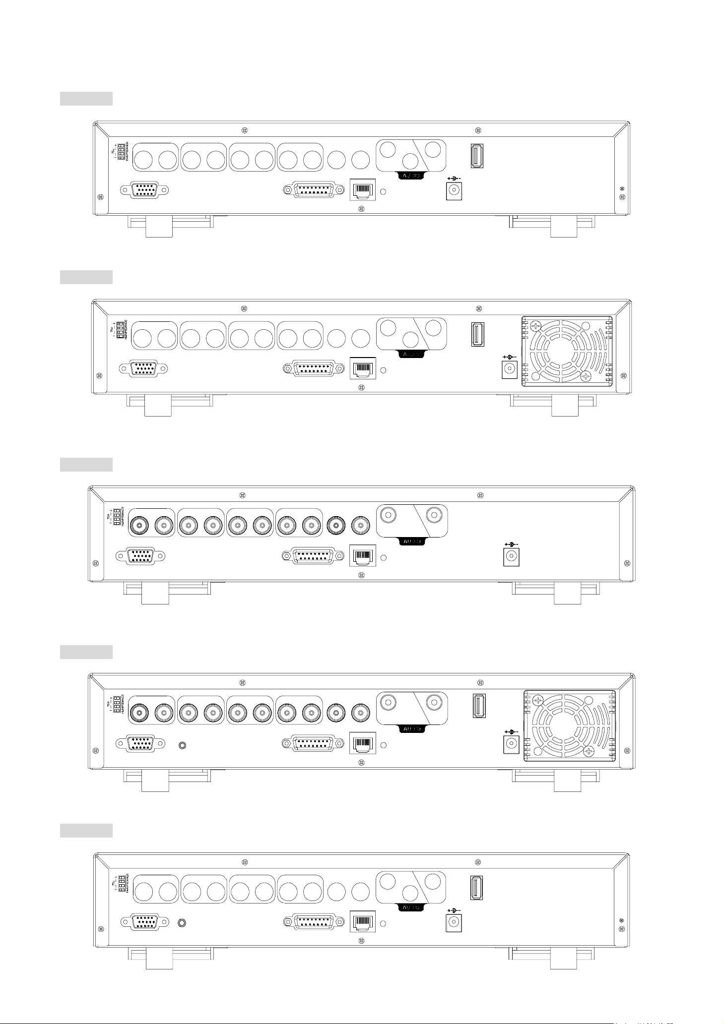
2.2 Rear Panels
‧ MODEL 1
FRONT AND REAR PANELS
‧ MODEL 2
LOOP
LOOP
INPUT
LOOP LOOP LOOP
INPUT
1
VD
/
2
INPUT
3
INPUT
4
EXT ERNA L I/O
CAL LMONIT OR
LAN
1
2
IN
LINK
ACT.
OUT
USB
DC 19V
INPUT
LOOP LOOP LOOP
INPUT
1
VD
/
2
INPUT
3
INPUT
4
EXTERNAL I/O
CAL LMONIT OR
LAN
1
IN
LINK
ACT.
OUT 2
USB
DC 19V
‧ MODEL 3
‧ MODEL 4
LOOP
LOOP
INP UT
1
VD
/
INPUT
LOOP LOOP LOOP
2
INP UT
3
INP UT
4
EXTERNAL I/O
CALLMONITOR
LAN
1
IN
LINK
ACT.
OUT
DC 19V
INP UT
1
VD
/
INPUT
LOOP LOOP LOOP
2
INP UT
3
INP UT
4
EXTERNAL I/OIR
CALLMONITOR
LAN
1
IN
LINK
ACT.
OUT
USB
DC 19V
‧ MODEL 5
LOOP
INPU T
LOOP LOOP LOO P
INPU T
1
VD
/
2
IR
INPUT
3
INPUT
4
EXTERNAL I/O
CAL LM ONITO R
LAN
1
2
IN
LINK
ACT.
OUT
USB
DC 19V
-6-
Page 11

FRONT AND REAR PANELS
1) 75Ω / HI-IMPEDANCE
When using LOOP function, please switch to HI-IMPEDANCE. Otherwise, please switch to 75Ω.
2) LOOP / INPUT (For channel 1~4)
LOOP: Video output connector.
INPUT: Connect to video sources, such as cameras.
Note: If you want to playback the video with audio, please connect an audio camera to the correct channel.
Model 1, 2 & 5: Please connect audio cameras to INPUT1 and/or INPUT 2 on the DVR rear panel.
Model 3 & 4: Please connect audio camera to INPUT 1 on the DVR rear panel
3) MONITOR
Connect to MAIN monitor.
4) CALL
Connect to CALL monitor to show the channel display one by one.
When any alarm is triggered, CALL monitor will show the image of the triggered channel for a period of time.
5) Audio IN
Connect to audio sources, such as cameras equipped with the audio function.
When users start recording, the audio input will also be recorded.
6) Audio OUT
Connect to a monitor or speaker with 1 mono audio output.
7) USB (For MODEL 1, 2, 4 & 5)
Support USB flash drive firmware update and file backup.
Note: For the list of compatible USB flash drives, please refer to “APPENDIX 5 COMPATIBLE USB FLASH
DRIVE BRAND” at page 55.
8) D/V Port (Digital Video Port)
Connect to VGA connecter.
9) IR (For Model 4 & 5)
Connect the IR receiver for remote control.
10) EXTERNAL I/O
Insert the supplied 15PIN DSUB to this port for connecting external devices (external alarm, PTZ camera, etc).
For detailed I/O port PIN configuration, please refer to “APPENDIX 2 PIN CONFIGURATION” at page 51.
11) LAN
Connect to Internet by LAN cable.
12) LINK ACT.
When your DVR is connected to the Internet, this LED will be on.
13) DC 19V
Connect to the supplied adapter.
-7-
Page 12
BASIC OPERATION
3. CONNECTIONS AND SETUP
3.1 Install HDD
The HDDs must be installed before the DVR is turned on. For detailed installation instructions, please refer to
section "APPENDIX 1 INSTALL HDD" at page 50.
3.2 Camera Connection
The cameras must be connected and power-supplied before the DVR is turned on. For detailed DVR video input /
output ports, please refer to section “2.2 Rear Panels” at page 6. For detailed external I/O port description, please refer to
section “APPENDIX 2 PIN CONFIGURATION” at page 51. For detailed camera setup, please refer to its own manual.
Note: When using LOOP function, set the impedance switch at your DVR rear panel to HI-IMPEDANCE to
decrease interferences. The default setting is 75Ω.
3.2.1 Normal Camera Connection
1) Connect the camera with indicated power supply.
2) Connect the camera video output to the DVR video input port with a coaxial cable and BNC connector.
For detailed camera title, ID, protocol and baud rate setup, please refer to section “6.4.5 Remote” at page 22.
3.2.2 PTZ Camera Connection
1) Connect the PTZ camera with indicated power supply.
2) Connect the PTZ camera video output to the DVR video input port with a coaxial cable and BNC connector.
3) For using DVR to control the PTZ camera, please connect the RS485-A line (brown) of the PTZ camera to the PIN11 of
the DVR DSUB solder side, and connect RS485-B line (orange) to the PIN10 of the DVR DSUB solder side.
And then solder them together in case of loosening.
Note: For detailed camera ID, protocol and baud rate setup at DVR side, please refer to section “6.4.5
Remote” at page 22. For detailed camera ID, protocol and baud rate setup at remote AP software side,
please refer to section “(1) Device” at page 39 (AP software system configuration). For detailed PTZ
control instructions, please refer to section “6.6.5 PTZ Camera Setup and Control” at page “30”.
3.3 External Device Connections
3.3.1 VGA Converter (Optional)
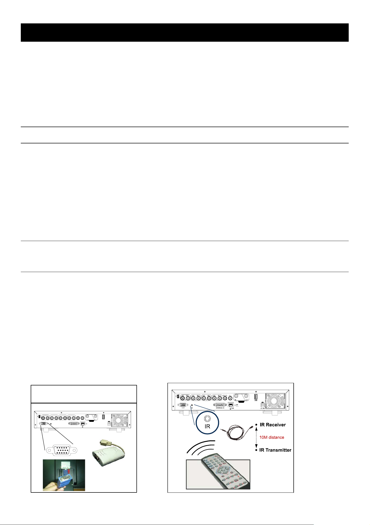
This optional peripheral (VGA Converter) allows your DVR to have VGA output function. Connect VGA CONNECTER
(A) to the MONITOR VGA CONNECTER (a), and connect VGA CONNECTER (B) to the DVR D/V PORT (b).
Please refer to the following figure as an example.
3.3.2 IR Transmitter
For MODEL 4 & MODEL 5 DVR, IR remote control is supported (Other models are optional). Please connect the IR
receiver line to the IR port on the DVR rear panel. And make sure the IR function is activated in the DVR menu (The
default setting is on). Please refer to the following figure as an example.
VGA
INPUT
LOOP
1
VD/
A: Connect to MonitorVideo Input
B: Connect to DVRVideo Output
1
INPUT2LOOP LOOP LOOP3INPUT4INP UT
D / V
CALLMONITOR
IN OUT
EXTERNAL I/OIR
LAN
USB
LINK
ACT.
DC 19V
B
A
MONITOR
-8-
Page 13

BASIC OPERATION
3.4 DVR Power Setup
This device should be operated only with the type of power source indicated on the manufacturer’s label. Connect the
indicated AC power cord to the power adapter, and plug into an electrical outlet. “POWER” LED will be on as red. Press
“POWER” button, and “POWER” LED will be on as green. It takes approximately 10 to 15 seconds to boot the system.
3.5 Date and Time Setting
Before operating your DVR, please set the date and time on your DVR first.
You can use the following buttons for menu setting:
BUTTON FUNCTION
UP, DOWN, LEFT, RIGHT Move the cursor.
+ , -
ENTER Go to the submenu / confirm the selection.
MENU Go to the menu list / confirm the change / exit the menu list.
1) Date and System Time:
Choose numbers / selections.
The menu path is as following: “MENU” → “DATE”.
2) Daylight Saving:
The menu path is as following: “MENU” → “DATE” → “DAYLIGHT SAVING”. Take the following option as an example:
DAYLIGHT SAVING
START 4TH-SUN-MAR 24:00:00
END 4TH-SUN-OCT 24:00:00
ADJUST 01:00
Note: Please DO NOT change the date or time of your DVR after the recording function is
activated. Otherwise, the recorded data will be disordered and you will not be able to find the
recorded file to backup by time search. If users change the date or time accidentally when the
recording function is activated, it’s recommended to clear all HDD data, and start recording again.
3.6 LAN or Internet Setup
3.6.1 STATIC IP
1) Build a Local Area Network (LAN) between DVR and PC/NB with network cable:
Your NB/PC and DVR must be under the same network domain to build the area network. Please change the IP
address of your PC/NB into 192.168.1.X (X can be the number between 1~255, except 10) and the subnet mask into
255.255.255.0 for communicate with the DVR.
Note: Before changing the network properties of your PC/NB, please write down the original network
properties in case you need to recover the properties later.
Install the supplied AP software on your NB/PC. Then, log into the DVR with the supplied AP software for the
following default DVR settings.
‧ The DVR default IP address: 192.168.1.10
‧ The DVR default account / password: admin
‧ The DVR default port: 80
2) Set DVR network setting in “SYSTEM CONFIG” → “Network” of the supplied AP:
In the “SYSTEM CONFIG” → “Network” of the supplied AP, select the “Static IP” in “IP TYPE” section. And then
type the “Server IP”, “Gateway”, “Net Mask” and “Web Port” (1~9999) information obtained from your ISP.
Press ”APPLY” button to confirm the setting.
3) Login your DVR via an Ethernet or dial-up network.:
After setting up the network information of the DVR and connect it to the network, you can use the IP address / Port
/ Account / Password you just entered in the supplied AP software to log into your DVR remotely.
-9-
Page 14

BASIC OPERATION
3.6.2 DDNS Apply
You need to apply a DDNS account before setting PPPoE or DHCP connection. DDNS is a service for transforming
the dynamic IP corresponding to a specific “Hostname”. For DDNS setup, please refer to the steps below.
‧ Go to a website which provides free DDNS services and apply a “Hostname”.
For example, go to http://www.dyndns.com.
‧ Enter all the information necessary for signing up an account according to the website instructions.
‧ Then, you will see the screen “Account Created”, and Dyndns will email the instructions to your specified E-mail
address for enabling your account. You must complete the procedure according to the instructions in the mail. That is
to must visit the confirmation address within 48 hours of the time that the e-mail was sent to complete the account
creation process. Then, you will see “Account Confirmed”. Your account is created successfully now.
‧ Log in with your account information and click ”My Service”.
‧ Click ”Add Host Services”.
‧ Click ”Add Dynamic DNS Host”.
‧ Fill in and choose the desired host name.
‧ The host name is created. You will be connected to the corresponding IP address whenever you enter this hostname.
3.6.3 Dynamic IP - PPPOE
1) Build a Local Area Network (LAN) between DVR and PC/NB with network cable:
Your NB/PC and DVR must be under the same network domain to build the area network. Please change the IP
address of your PC/NB into 192.168.1.X (X can be the number between 1~255, except 10) and the subnet mask into
255.255.255.0 for communicate with the DVR.
Install the supplied AP software on your NB/PC. And then login the DVR with the supplied AP software for the
following default DVR settings.
‧ The DVR default IP address: 192.168.1.10
‧ The DVR default account / password: admin
‧ The DVR default port: 80
2) Set DVR network setting in “SYSTEM CONFIG” → “Network” of the supplied AP:
In the “SYSTEM CONFIG” → “Network” of the supplied AP, select the “PPPOE” in “IP TYPE” section. And then
type the “User Name” and “Password” obtained from your ISP. Press ”APPLY” button to confirm the setting.
3) Set DVR DDNS setting in the “SYSTEM CONFIG” → “DDNS” of the supplied AP software:
‧ DDNS: Choose “Enable”.
‧ User Name: Type your DDNS account.
‧ Password: Type your DDNS password.
‧ Domain: Type the “Host Name” you applied previously (EX: securityanytime.dyndns.org).
‧ System Name: Choose the DDNS server where you applied the domain name (EX: dyndns).
‧ After setting, please press “APPLY” button to confirm and finish the setting.
4) Login your DVR via an Ethernet or dial-up network.:
After setting up the network information of the DVR and connect it to the network, you can type DDNS host name,
default user name and password in the supplied AP software login page to log into your DVR remotely.
-10-
Page 15

BASIC OPERATION
3.6.4 Dynamic IP - DHCP
Get a router and use the default IP address provided by your router to login to the router. Enable the DHCP server
and set the starting IP address, ending IP address and lease time. The DHCP Server of the router will automatically
allocate an unused IP address from the IP address pool to the requesting computer.
1) Build a Local Area Network (LAN) between DVR and PC/NB with network cable:
Your NB/PC and DVR must be under the same network domain to build the area network. Please change the IP
address of your PC/NB into 192.168.1.X (X can be the number between 1~255, except 10) and the subnet mask into
255.255.255.0 for communicate with the DVR.
Install the supplied AP software on your NB/PC. And then login the DVR with the supplied AP software for the
following default DVR settings.
‧ The DVR default IP address: 192.168.1.10
‧ The DVR default account / password: admin
‧ The DVR default port: 80
2) Set DVR network setting in “SYSTEM CONFIG” → “Network” of the supplied AP:
In the “SYSTEM CONFIG” → “Network” of the supplied AP, select the “DHCP” in “IP TYPE” section. Then
press ”APPLY” button to confirm the setting.
Set DVR DDNS setting in the “SYSTEM CONFIG” → “DDNS” of the supplied AP software.
‧ DDNS: Choose “Enable”.
‧ User Name: Type your DDNS account.
‧ Password: Type your DDNS password.
‧ Domain: Type the “Host Name” you applied previously (EX: securityanytime.dyndns.org).
‧ System Name: Choose the DDNS server where you applied the domain name (EX: dyndns).
‧ After setting, please press “APPLY” button to confirm and finish the setting.
3) Login your DVR via an Ethernet or dial-up network:
After setting up the network information of the DVR and connect it to the network, you can type DDNS host name
and default user name and password in the supplied AP software login page to log into your DVR remotely.
-11-
Page 16
3.7 Password and User Name Setting
3.7.1 DVR Password Setting
The menu path is as following: MENU → ADVANCE → SYSTEM → PASSWORD → SETUP → ADMIN
PASSWORD / GUEST PASSWORD. You can use the following buttons for menu setting:
BUTTON FUNCTION
UP, DOWN, LEFT, RIGHT Move the cursor.
+ , -
ENTER Go to the submenu / confirm the selection.
MENU Go to the menu list / confirm the change / exit the menu list.
1) Admin password:
Password for supervisor, allow all the setup of DVR.
Choose numbers / selections.
BASIC OPERATION
2) Guest password:
Only allow viewing the live streaming video and sequencing display, shifting the channel display, and locking keys.
3.7.2 Remote Login Password and User Name Setting
In the “SYSTEM CONFIG” → “Account” of the supplied AP software, you can set up user accounts (max. 5
accounts), password, life time, and authority level (max. 5 users on line at the same time) for remote login to the DVR. For
detailed instructions, please refer to “(1) Account” in the section “7.5.4 General” at page 46.
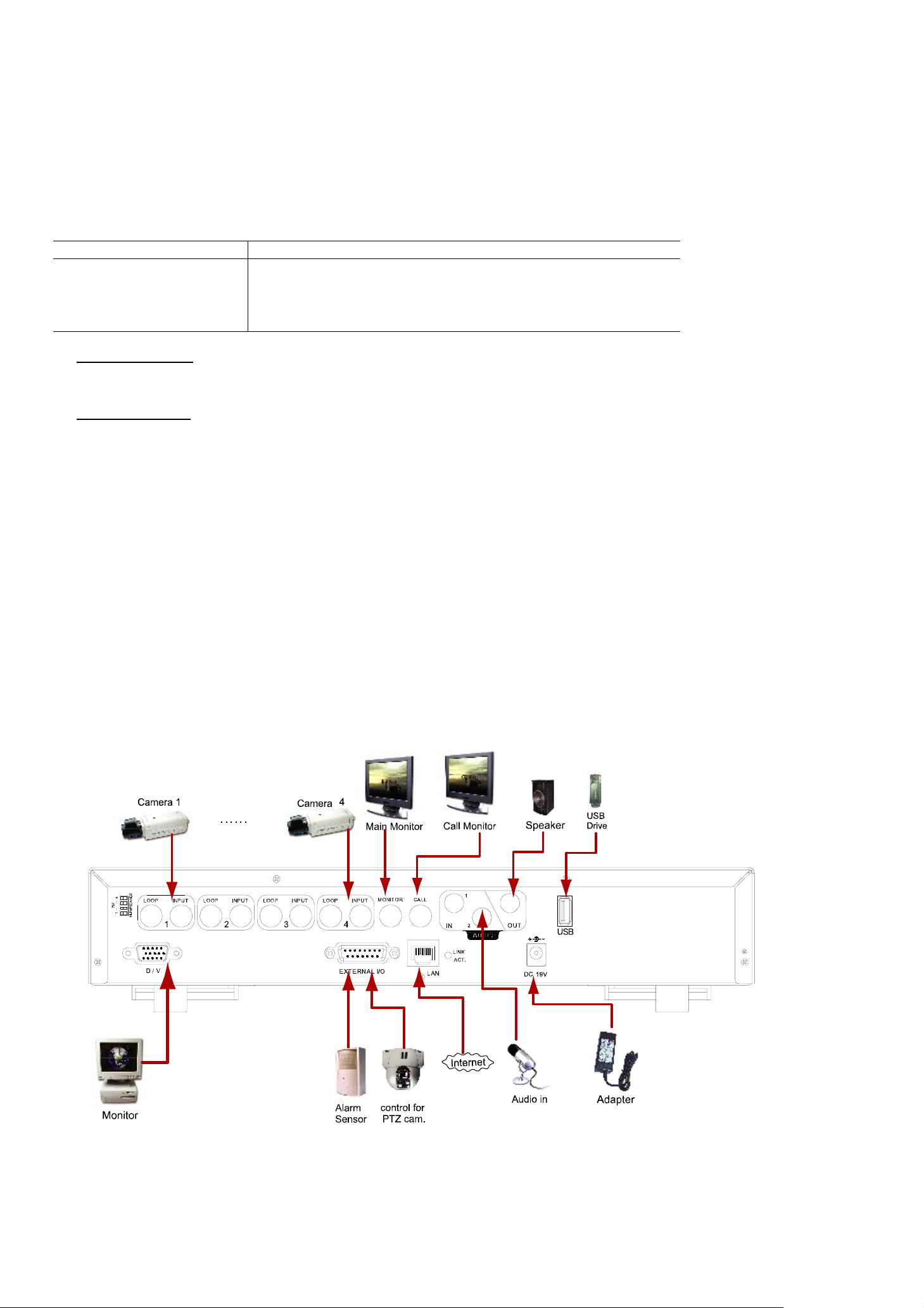
3.8 System Diagram
After you finish all the connections, a surveillance system is established and you can experience the marvelous and
useful functions of this DVR. The diagram below illustrates all the available connections of this DVR for you to picture your
surveillance system (Take Model 1 as an example).
-12-
Page 17

BASIC OPERATION
4. BASIC OPERATION
4.1 Recording
This device offers three recording modes: manual record, event record and timer record. If the power is off
accidentally, the recorded video data will not be lost and is safely stored in the HDD. The device will return to the original
recording status after the power is on again.
‧ MANUAL RECORD (continuous recording)
Recording is initiated by manually pressing “REC” button on the front panel.
This mode is indicated by the sign “z” on the screen.
‧ EVENT RECORD (triggered by motion and external alarm)
When this function is activated, the recording is triggered by motion or external alarms.
This mode is indicated by the sign " " (motion) or " " (external alarm) on the screen.
‧ TIMER RECORD (scheduled time)
Recording is scheduled by TIMER function.
Indicated by the wording “TIMER RECORD” on the monitor.
Note: When the recording function is activated, please DO NOT change the date or time on your DVR. The recorded
data will be disordered and you will not be able to find the recorded data to backup by time search.
If users change the date or time accidentally when the recording function is activated, please clear all HDD data,
and start recording again.
Overwriting Mode
If the overwriting mode is enabled, you will see “-OW-” (1) under the recording mode except the system time (2),
available HDD capacity (3), recording icon (4) and channel title (5).
When the HDD is full under “-OW-” recording mode, the previous recorded data will be overwritten without notice.
Under “-OW-" mode, this device will clear 8GB data from the oldest for continuous recording once the HDD is full.
To turn on/off this mode, please refer to the section “6.4.6 System” at page 22.
-13-
Page 18

BASIC OPERATION
4.2 Playback
Press “ ” or “PLAY” button on the front panel, and the device will display the last recorded video.
Note: There must be at least 8192 images of recorded data for playback to work properly. If not, the device
will stop playback. For example, if the IPS is set to 30, the recording time should be at least 273
seconds (8192 images / 30 IPS) for the playback to work properly.
Playback related operations are described below:
‧ Fast Forward ( ) / Fast Rewind ( )
You can increase the speed for fast forward and rewind on this device. In the playback mode:
Press “ “ once to get 4X speed forward and press twice to get 8X speed, etc. And the maximum speed is 32X.
Press “ “ once to get 4X speed rewind and press twice to get 8X speed, etc. And the maximum speed is 32X.
‧ Pause ( ) / Image Jog
Press “ “ button to pause the video playback.
In the Pause mode:
Press “ “ button once to get one frame forward.
Press “ “ button once to get one frame rewind.
‧ Stop ( )
Pressing “ ” button under all circumstances will return this device to live monitoring mode.
‧ Channel Display Mode
Display mode:
Press “ ” button to show the 4 channel display modes.
Full screen view:
Press one of the number buttons from 1-4 to show the selected channel in the full screen.
Under the playback mode, you can select a channel to display the live video instead of the playback video.
For details, please refer to “Position of Channel Display” in section ”2.1 Front Panels” at page 4.
‧ Slow Playback
Model 1, 2 & 5: Press “SLOW” button to get 1/4X speed playback and press twice to get 1/8X speed playback.
Model 3 & 4: Press “SLOW” button to get 1/2X speed playback.
‧ Audio
SLOW
ZOOM
Press
AUDIO
or buttons at the same time to select to play either live (L) or playback (P) sound.
AUDIO 1 (L) – 1st audio channel, live audio;
AUDIO 1 (P) – 1st audio channel, playback audio
AUDIO 2 (L) – 2nd audio channel, live audio (Only Model 1, 2 & 5 have AUDIO 2 option)
AUDIO 2 (P) – 2nd audio channel, playback audio (Only Model 1, 2 & 5 have AUDIO 2 option)
Note: If you want to playback the video with audio, please connect an audio camera to the correct channel.
Model 1, 2 & 5: Please connect audio cameras to INPUT1 and/or INPUT 2 on the DVR rear panel.
Model 3 & 4: Please connect audio camera to INPUT 1 on the DVR rear panel.
-14-
Page 19
5. MAIN MENU
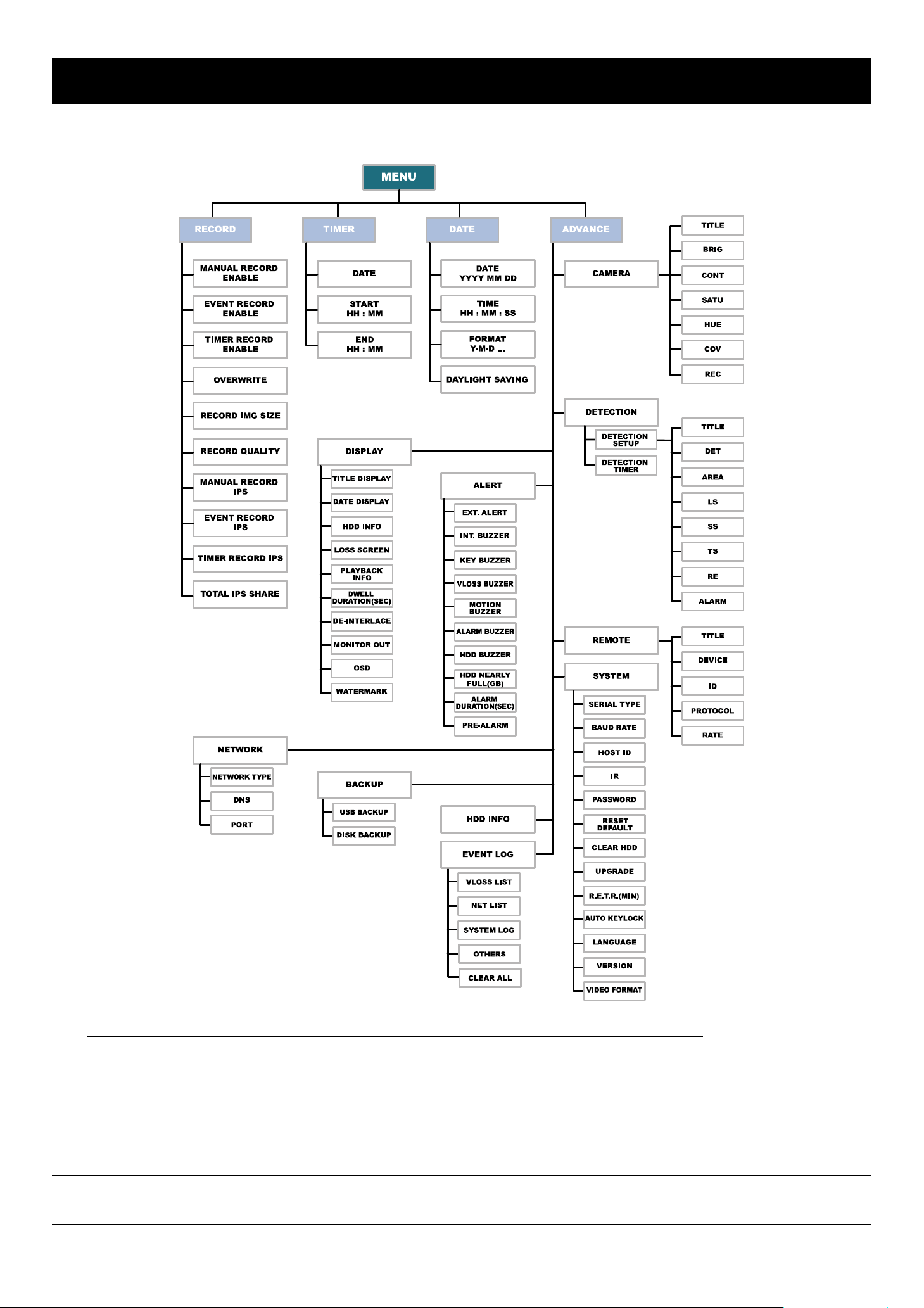
5.1 Menu Tree
MAIN MENU
You can use the following buttons for menu setting:
BUTTON FUNCTION
UP, DOWN, LEFT, RIGHT Move the cursor.
+ , -
ENTER Go to the submenu / confirm the selection.
MENU Go to the menu list / confirm the change / exit the menu list.
Note: The supported functions of Backup, IR remote control and R.E.T.R. vary according to the model you're
using. Please refer to the specification.
Choose numbers / selections.
-15-
Page 20

MENU FUNCTION
6. MENU FUNCTION
6.1 Record
In this menu list, you can set record settings. Press “MENU” button on the front panel to enter the main menu list. The
default admin password is 0000. Enter the default password, and press “ENTER”. Users can change the password later.
Please refer to the section “6.4.6 System” at page 22.
Move the cursor to “RECORD”, and press ” ENTER”. The screen will show the following options:
MENU
RECORD
TIMER OVERWRITE
DATE RECORD IMG SIZE
ADVANCE RECORD QUALITY
MANUAL RECORD IPS
EVENT RECORD IPS
TIMER RECORD IPS
TOTAL IPS SHARE
The submenu items are described below:
MANUAL RECORD ENABLE
EVENT RECORD ENABLE
TIMER RECORD ENABLE
RECORD
1) MANUAL RECORD ENABLE
Start / stop the manual recording function.
2) EVENT RECORD ENABLE
Start / stop the event recording function. When this function is enabled, the recording will be triggered by any motion or
external alarm.
3) TIMER RECORD ENABLE
Start / stop the timer recording function.
4) OVERWRITE
Select to overwrite previous recorded data in your HDD. When the HDD is full under O/W recording mode, this device
will clear 8GB data from the oldest for continuous recording without notice.
5) RECORD IMG SIZE
Select one of the image sizes: FRAME or CIF.
Note: When changing the record image size, please stop recording first.
6) RECORD QUALITY
Select one of the 4 quality options: BEST, HIGH, NORMAL & BASIC.
7) MANUAL RECORD IPS
Select the images per second for MANUAL RECORD.
8) EVENT RECORD IPS
Select the images per second for EVENT RECORD (Recording that is triggered by alarm or motion).
9) TIMER RECORD IPS
Select the images per second for TIMER RECORD (Recording that is activated according to the scheduled time.).
The IPS options are as following:
NTSC PAL
FRAME 30, 15, 7, 3 FRAME 25, 12, 6, 3
CIF 120, 60, 30, 15 CIF 100, 50, 25, 12
10) TOTAL IPS SHARE
This option is used to select how this device divides its total IPS. The more IPS one channel gets, the more smooth
the recorded video will be played. Select one of the IPS share setting: FIX or GROUP.
FIX: IPS per channel = RECORD IPS ÷ number of channels
GROUP (Suitable for Frame mode):
IPS per channel = RECORD IPS ÷ 2 ÷ number of channels in a group which is under recording.
NOTE: For Model 3 & 4, the total IPS share is always “FIX”.
-16-
Page 21

MENU FUNCTION
6.2 Timer
Press “MENU” button on the front panel to enter the main menu list. Move the cursor to “TIMER”, and press ”ENTER”.
The screen will show the following options.
MENU
RECORD DAILY 08 : 00 - 18 : 00
TIMER
DATE MON-FRI 18 : 00 - 23 : 00
ADVANCE OFF 00 : 00 - 00 : 00
OFF 00 : 00 - 00 : 00
OFF 00 : 00 - 00 : 00
The submenu items are described below:
1) DATE
Select from the following 11 options to schedule up to 7 sets of recording days: SUN / MON / TUE / WED / THU / FRI /
SAT / MON–FRI / SAT-SUN / DAILY / OFF.
If you plan to set the timer recording across the midnight, there are two ways to set the timer recording schedule.
Please check the examples below.
Example 1:
If you only want to set the recording schedule from Sunday 23:30 to Monday 23:30, set the schedule as Sunday from
23:30 to 23:30.
Example 2:
DATE START END
OFF 00 : 00 - 00 : 00
SUN 06 : 00 - 23 : 00
RECORD
If you want to set the recording schedule from Sunday 08:00 to Monday 15:00, set the schedule as Sunday from 08:00
to 24:00, and Monday 24:00 to 15:00.
Note: Before setting the timer recording schedule, please turn on “TIMER RECORD ENABLE” in “RECORD”
menu list. For details, please refer to the section “6.1 Record” at page 16.
6.3 Date
In this menu list, you can set up the system date and time for this device.
Note: When the recording function is activated, please DO NOT change the date or time on your DVR. For
details, please refer to the section “4.1 Recording” at page 13.
Press “MENU” button on the front panel to enter the main menu list. Move the cursor to “DATE”, and press ”ENTER”.
The screen will show the following options.
MENU
RECORD DATE 2006 – Dec - 01 12 : 15 : 30
TIMER FORMAT Y - M - D
DATE
ADVANCE
The submenu items are described below:
DAYLIGHT SAVING ON
DATE
1) DATE:
Set the current date and time. The default order is “YEAR – MONTH – DATE HOUR : MIN : SEC”.
2) FORMAT
Select one date format from the following 3 options: Y-M-D, M-D-Y, D-M-Y.
3) DAYLIGHT SAVING
Specify whether to use daylight-saving time (ON / OFF). If it’s set to ON, press “ENTER” to go to its submenu for
further settings. You will see a similar screen as following.
DAYLIGHT SAVING
START 4TH - SUN - MAR 24 : 00 : 00
END 4TH - SUN - OCT 24 : 00 : 00
ADJUST 01 : 00
Set the start time and end time, and adjust the daylight saving time in hour. The above example means during the
daylight-saving time period (starting from the 4th Sunday of March and ending on the 4th Sunday of October), the
system time will plus one hour.
-17-
Page 22

6.4 Advance
Press “MENU” button on the front panel to enter the main menu list. Move the cursor to “ADVANCE”, and
press ”ENTER”. The screen will show the following options.
MENU FUNCTION
MENU
RECORD DISPLAY
TIMER ALERT
DATE REMOTE
ADVANCE
NETWORK
BACKUP
HDD INFO
EVENT LOG
CAMERA
DETECTION
SYSTEM
ADVANCE
6.4.1 Camera
In this submenu, you can make advanced camera settings, such as changing the camera title, or adjust the
brightness. Move the cursor to “CAMERA”, and press ”ENTER”. You will see a similar screen as the following:
ADVANCE CAMERA
CAMERA
DETECTION
DISPLAY 02 110 120 128 128 NO YES
ALERT 03 110 120 128 128 NO YES
REMOTE 04 110 120 128 128 NO YES
SYSTEM
NETWORK
BACKUP
HDD INFO
EVENT LOG
The submenu items are described below:
TITLE BRIG CONT SATU HUE COV REC
01 110 120 128 128 NO YES
1) TITLE
You can change the default camera naming here. The default title is the channel number.
Move the cursor to the camera title you want to change, and press “ENTER” to access the character selection screen.
Assign a new name to the camera up to six characters (letters or symbols).
2) BRIG/CONT/SATU/HUE
You can adjust the brightness/contrast/saturation/hue of each channel here. The default value of BRIG is 110, and
others are 128. The value is adjustable from 0 to 255.
3) COV
Select if you want to mask the selected channel under recording (YES/NO). When this function is activated, the
wording “COV” will be shown on the screen.
4) REC
Select if you want to enable recording for the selected channel (YES/NO). When this function is activated, the symbol
“z” will be shown on the channel screen.
6.4.2 Detection
In this submenu, you can set up detection-related functions: DETECTION SETUP and DETECTION TIMER.
Move the cursor to “DETECTION”, and press ”ENTER”. The screen will show the following options.
ADVANCE DETECTION
CAMERA
DETECTION
DISPLAY
ALERT
REMOTE
SYSTEM
NETWORK
BACKUP
HDD INFO
EVENT LOG
DETECTION SETUP
DETECTION TIMER
-18-
Page 23
(1) Detection Setup
Move the cursor to “DETECTION SETUP”, and press ”ENTER”. You will see a similar screen as the following:
DETECTION
DETECTION
MENU FUNCTION
DETECTION SETUP
TITLE DET AREA LS SS TS RE ALARM
DETECTION TIMER 01 ON SETUP 07 03 02 10 LOW
02 OFF SETUP 07 03 02 10 OFF
03 OFF SETUP 07 03 02 10 LOW
04 OFF SETUP 07 03 02 10 HIGH
PREV NEXT
The submenu items are described below:
1) TITLE:
Show the camera title of each channel set in “CAMERA”.
2) DET: Select if you want to activate the motion detection function for the selected channel (ON/OFF).
3) AREA
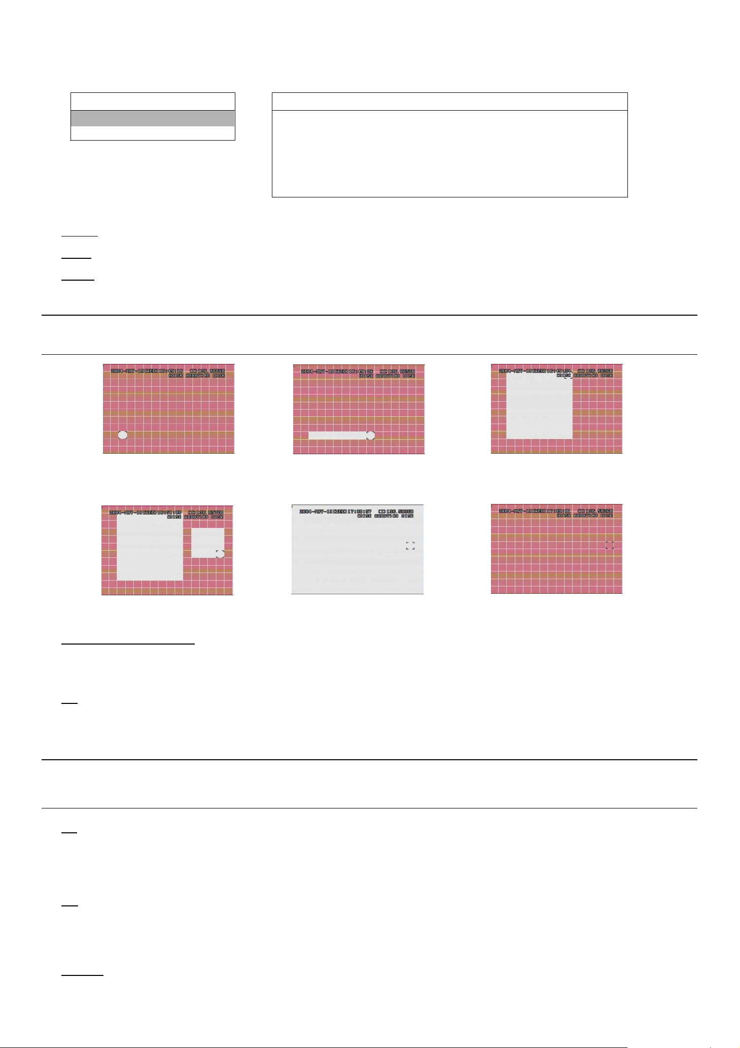
Press “ENTER” button to set the detection area. You will see similar screens as the following:
Pink blocks represent the area that is not being detected while the transparent blocks are the area under detection.
Note: If the connected video output device is LCD monitor, but the “MONITOR OUT” setting in “DISPLAY”
menu is "MAIN", the motion detection area setting will be disabled.
Press “ENTER” to confirm
the start area.
You can also up set up
multi-detection areas.
Press “LEFT” or “RIGHT” to
choose the width of the area
Press “-” to set the whole
area under detection
Press “UP” or “DOWN” to choose
the height of the area, and press
“ENTER” again to confirm.
Press “+” to set the whole
area undetected
4) LS (Level of Sensitivity)
“LS” is to set the sensitivity of comparing two different images. The smaller the value is, the higher sensitivity for motion
detection. The highest sensitivity setting is 00, and the lowest sensitivity setting is 15. The default value is 07.
5) SS (Spatial Sensitivity)
“SS” is to set the sensitivity for detecting the size of one object (the number of the grids) on the screen. The smaller the
value is, the higher sensitivity for motion detection.
The highest sensitivity setting is 00, and the lowest sensitivity setting is 15. The default setting is 03.
Note: The de fault s ettin g of SS is 03, which mea ns once an object is detected more than 3 grids, the system
will get triggered. So the value of SS must be less than the number of grids that you set up for the
motion detection area.
6) TS (Time of Sensitivity)
“TS” is to set the sensitivity regarding how long one object stays in the detection area and triggers the recording. The
smaller the value is, the higher sensitivity for motion detection.
The highest sensitivity setting is 00, and the lowest sensitivity setting is 15. The default setting is 02.
7) RE (Reference)
“RE” is to set a reference for detection. The default value is 10, which means the DVR will compare 10 continuous
images at one time according to the sensitivity of LS, SS, TS simultaneously.
The bigger the value is, the higher sensitivity for motion detection. The highest sensitivity is 61.
8) ALARM
Select LOW / HIGH for the alarm polarity. The default alarm value is OFF.
-19-
Page 24

(2) Detection Timer
Move the cursor to “DETECTION TIMER”, and press ”ENTER”. You will see a similar screen as the following:
MENU FUNCTION
DETECTION
DETECTION SETUP DATE START END
DETECTION TIMER
DAILY 08 : 00 - 18 : 00
SUN 06 : 00 - 23 : 00
MON-FRI 18 : 00 - 23 : 00
OFF 00 : 00 - 00 : 00
Set the date, start time and end time for the detection function. The setting method is similar to “TIMER”. Please refer
to the section “6.2 Timer” at page 17.
OFF 00 : 00 - 00 : 00
OFF 00 : 00 - 00 : 00
OFF 00 : 00
DETECTION TIMER
-
00 : 00
6.4.3 Display
In this menu list, you can check and change some display settings.
Move the cursor to “DISPLAY”, and press ”ENTER”. You will see a similar screen as the following:
ADVANCE
CAMERA
DETECTION DATE DISPLAY ON
DISPLAY
ALERT LOSS SCREEN BLUE
REMOTE PLAYBACK INFO NORMAL
SYSTEM DWELL DURATION (SEC) 2
NETWORK DE-INTERLACE ON
BACKUP MONITOR OUT MAIN
HDD INFO OSD SETUP
EVENT LOG WATERMARK ON
The submenu items are described below:
TITLE DISPLAY ON
HDD INFO ON
DISPLAY
1) TITLE DISPLAY
Select to display the channel title or not (ON / OFF).
2) DATE DISPLAY
Select to display the date or not (ON / OFF).
3) HDD INFO
Select to display HDD remaining capacity or not (ON / OFF).
4) LOSS SCREEN
Set the color for the video loss screen (BLUE / BLACK).
5) PLAYBACK INFO
Set the position where playback information will be indicated: CENTER or NORMAL (on the button of the left-hand
side of the screen).
6) DWELL DURATION (SEC)
Set the duration time of each channel in second for CALL MONITOR (2 / 4 / 8 / 16).
7) DE-INTERFACE
Select to enable or disable “DE-INTERLACE” function (ON / OFF).
8) MONITOR OUT
Select "MAIN" when the video output device is CRT monitor; select "VGA" when the video output device is LCD
monitor.
Note: If the connected video output device is LCD monitor, but the setting here is "MAIN", the motion
detection area setting will be disabled.
For LCD monitor connection, you also need a VGA converter (optional).
9) OSD (Multilingual)
You can set the customized OSD color here.
-20-
Page 25

MENU FUNCTION
Move the cursor to “OSD”, and press ”ENTER” to go to the setup view. You will see a similar screen as the following:
DISPLAY
OSD SETUP
TITLE DISPLAY ON MENU TITLE BACKGROUND GREEN
DATE DISPLAY ON MENU BACKGROUND YELLOW
HDD INFO ON CURSOR YELLOW
LOSS SCREEN BLUE MESSAGE TITLE BACKGROUND RED
PLAYBACK INFO NORMAL MENU STYLE 3D
DWELL DURATION (SEC) 2 MENU TITLE FONT YELLOW
DE-INTERLACE ON MENU FONT PURE WHILE
MONITOR OUT MAIN RECORD SYMBOL GREEN
OSD SETUP
ALERT FONT RED
WATERMARK ON
The default OSD color setting is as the above screen. There are 11 colors for your choice: WHITE, YELLOW, CYAN,
GREEN, MAGENTA, RED, BLUE, BLACK, GRAY, PURE GRAY, and PURE WHITE.
10) WATERMARK
In the playback mode of the software AP, users can prove the authenticity of the backup video. If the backup video
had been modified, the video image will turn to light red, and the playback will be paused.
Note: This function is always on and non-switchable.
6.4.4 Alert
In this menu list, you can set alerts for different kinds of situations, such as when HDD is full.
Move the cursor to “ALERT”, and press ”ENTER”. You will see a similar screen as the following:
ADVANCE
CAMERA
DETECTION INT. BUZZER ON
DISPLAY KEY BUZZER ON
ALERT
REMOTE MOTION BUZZER ON
SYSTEM ALARM BUZZER ON
NETWORK HDD BUZZER ON
BACKUP HDD NEARLY FULL (GB) 05
HDD INFO ALARM DURATION (SEC) 05
EVENT LOG PRE-ALARM OFF
The submenu items are described below:
1) EXT. ALERT
Select to enable or disable the sound when any external alarm is triggered (ON / OFF).
2) INT. BUZZER
Select to enable or disable the sound (ON / OFF) for all the internal buzzers: KEY BUZZER, VLOSS BUZZER,
MOTION BUZZER, ALARM BUZZER, and HDD BUZZER.
ALERT
EXT. ALERT ON
VLOSS BUZZER ON
Note: When this item is set to OFF, item 3) to item 7) will be disabled even though they are set to ON.
3) KEY BUZZER
Select to enable or disable the sound when pressing the buttons on the front panel (ON / OFF).
4) VLOSS BUZZER
Select to enable or disable the sound when video loss happened (ON / OFF).
5) MOTION BUZZER
Select to enable or disable the sound when any motion alarm is triggered (ON / OFF).
6) ALARM BUZZER
Select to enable or disable the sound when any internal alarm is triggered (ON / OFF).
7) HDD BUZZER
Select to enable or disable the sound when HDD is full (ON / OFF).
8) HDD NEARLY FULL (GB)
If HDD buzzer is enabled, you can choose to have a buzzer notification when the HDD available capacity is 5/10/15
GB left.
-21-
Page 26

MENU FUNCTION
9) ALARM DURATION (SEC)
Press “ENTER” or “+” / “-” button to set the duration time of alarm recording in second (5 / 10 / 20 / 40).
10) PRE-ALARM
Select to enable or disable the pre-alarm function (ON / OFF).
When pre-alarm and event recording functions are both activated, the DVR will record 8MB data before any alarm /
motion is triggered.
6.4.5 Remote
In this menu list, you can set up remote devices to work properly.
Move the cursor to “REMOTE”, and press ”ENTER”. You will see a similar screen as the following:
ADVANCE
CAMERA
DETECTION 01 CAMERA 000 NORMAL 02400
DISPLAY 02 PTZ 255 P-D 02400
ALERT 03 CAMERA 000 NORMAL 02400
REMOTE
SYSTEM
NETWORK
BACKUP
HDD INFO
EVENT LOG
The submenu items are described below:
1) TITLE
Show the camera title of each channel set in “CAMERA”.
2) DEVICE
Select the device type (CAMERA / PTZ) according to the connected camera for each channel.
3) ID
Set the ID number (0 ~ 255) for a PTZ camera.
After connecting to a PTZ camera correctly, the default ID of the PTZ camera will be shown on the screen.
TITLE DEVICE ID PROTOCOL RATE
04 CAMERA 000 NORMAL 02400
REMOTE
4) PROTOCOL
Select NORMAL (our protocol) or P-D (PELCO-D) protocol.
5) RATE
Set the baud rate of each channel (2400 / 4800 / 9600 / 19200 / 57600). For the connected cameras, such as PTZ and
speed dome cameras, etc., please make sure their baud rate setting is the same as the setting here.
Note: For detailed PTZ camera connection & setup, please refer to the section “3.2.2 PTZ” at page 8, and
“6.6.5 PTZ Camera Setup and Control” at page 30.
6.4.6 System
In this menu list, you can check or change some system settings.
Move the cursor to “SYSTEM”, and press ”ENTER”. You will see a similar screen as the following:
ADVANCE
CAMERA
DETECTION BAUD RATE 02400
DISPLAY HOST ID 001
ALERT IR ON
REMOTE PASSWORD SETUP
SYSTEM
NETWORK CLEAR HDD EXT 003
BACKUP UPGRADE NO
HDD INFO R.E.T.R. (MIN) 03
EVENT LOG AUTO KEYLOCK NEVER
LANGUAGE ENGLISH
VERSION 1088-10-K2-04-AA-11
VIDEO FORMAT NTSC
SERIAL TYPE RS-485
RESET DEFAULT RESET
SYSTEM
-22-
Page 27

MENU FUNCTION
The submenu items are described below:
1) SERIAL TYPE
Press “ENTER” or “+” / “-” button to set the serial type of the DVR (RS-485 / RS-232).
2) BAUD RATE
Press “ENTER” or “+” / “-” button to set the baud rate of the DVR (2400 / 9600 / 19200 / 57600).
3) HOST ID
Press “ENTER” or “+” / “-” button to set the ID of the DVR (0 ~ 255).
4) IR (For Model 4 & 5)
Press “ENTER” or “+” / “-” button to enable or disable IR function (ON / OFF).
5) PASSWORD
Press “ENTER” to reset the password for accessing the DVR system (ADMIN PASSWORD or GUEST PASSWORD).
You can set the password up to 4 digits.
Note: Users who use guest password to access the DVR will be only allowed to view the live streaming video
and sequence display, shift the channel display, and lock keys.
6) RESET DEFAULT
Press “ENTER” to reset all settings as default, and select “YES” to confirm or “NO” to cancel.
7) CLEAR HDD
Press “ENTER”, and select “YES” to confirm to clear HDD or “NO” to cancel.
8) UPGRADE (This function is only for Model 1, 2, 4 and 5)
Press “ENTER”, and select “YES” to confirm upgrade or “NO” to cancel.
Note: To use this function, you need to have the upgrade file saved in a compatible USB flash drive, and
insert it into the USB port at the front or rear panel.
Note: Do not disconnect the power of your DVR while the upgrade process is in progress, or the DVR
functions may not work normally or be unable to use.
9) R.E.T.R. (MIN) (For Model 5)
‧ R.E.T.R. Activation
Press “MENU” + “-” buttons on the front panel to enable R.E.T.R. function 3 / 5 / 10 minutes later. A message
“R.E.T.R. ON” will be shown on the screen (in white text), and after the RETR function is activated, the message
“R.E.T.R.” shown on the screen will turn to red.
‧ R.E.T.R. Off
Press any key (except “ ” or “POWER” buttons) and enter the password to turn off the RETR function.
10) AUTO KEYLOCK
Set the time-out in second after which the key lock function is activated (Never / 10 / 30 / 60).
11) LANGUAGE (Support multi-language)
Press “ENTER” to select the language of the OSD.
12) VERSION
Here shows the firmware version information.
13) VIDEO FORMAT
Here shows the information of the DVR video format (NTSC / PAL).
-23-
Page 28

MENU FUNCTION
6.4.7 Network
In this menu list, you can set up the network. For detailed network setup, please refer to the section “3.6 LAN or Internet
Setup” at page 9.
Move the cursor to “NETWORK”, and press ”ENTER”. You will see a similar screen as the following:
ADVANCE
CAMERA
NETWORK TYPE STATIC
DETECTION DNS 168. 95. 1. 1
DISPLAY PORT 0080
ALERT
REMOTE
SYSTEM
NETWORK
BACKUP
HDD INFO
EVENT LOG
The submenu items are described below:
1) NETWORK TYPE
There are 3 network types: STATIC, PPPOE and DHCP.
‧ STATIC
Select NETWORK TYPE, press “+” or “-” button to set the network type as STATIC, and then press “ENTER” to
go to the submenu of the network. In the submenu of network type, use “+” or “-” button to set all the information
NETWORK
needed in the DVR. See the example below, and refer to the section “3.6.1 STATIC IP” at page 9 for details.
STATIC
IP 160 . 121 . 346 . 236
GATEWAY 160 . 121 . 346 . 236
NETMASK 255 . 255 . 255 . 254
‧ PPPOE
This PPPoE function needs to have one “username” and one “password” subscribed from one ISP supplier.
For detailed PPPoE settings, please follow the AP (Licensed Software AP) setup, and then refer to the section
“3.6.4 Dynamic IP - DHCP” at page 11, and “(1) DDNS” in section “7.5.1 Network” at page 37.
‧ DHCP
The DHCP function needs to be supported by a router or a cable modem network with DHCP services.
For detailed DHCP settings, please follow the AP (Licensed Software AP) setup, and then refer to the section “3.6.3
Dynamic IP - PPPOE” at page 10, and “(1) DDNS” in section “7.5.1 Network” at page 37.
Note: DHCP and PPPoE network types need to apply DDNS services to get “Hostname” to correspond to the
dynamic IP address. For detailed DDNS settings, please refer to “(1) DDNS” in section “7.5.1
Network” at page 37.
2) DNS
Key in the IP address of the domain name server obtained from your ISP (Internet Service Provider).
3) PORT
The valid number ranges from 1 to 9999. The default value is 80.
Note: Typically, the TCP port used by HTTP is 80. However in some cases, it is better to change this port
number for added flexibility or security.
-24-
Page 29

MENU FUNCTION
6.4.8 Backup
The backup file can be played directly in your PC via the supplied licensed software AP, or via other media players
(ex: Windows Media Player or RealPlayer) after the file is converted to “AVI” format. For detailed AP playback, please refer
to the section “7.4 Playback Operation” at page 35.
Note: For model 3, you need to backup from network via supplied AP software.
Note: Before making a video backup with audio, you need to check whether there’s any audio camera connected to
the channel which supports audio recording, and there’s any recorded data for the channel.
For model 1, 2 & 5: Please choose CH1 and / or CH2 to backup video with audio.
For model 3 & 4: Please choose CH1 to backup video with audio.
Move the cursor to “BACKUP”, and press ”ENTER”. You will see the following options:
ADVANCE
CAMERA
BACKUP
USB BACKUP
DETECTION DISK BACKUP
DISPLAY
ALERT
REMOTE
SYSTEM
NETWORK
BACKUP
HDD INFO
EVENT LOG
1) USB BACKUP (USB backup function is only for Model 1, 2, 4 & 5)
Before making USB backup, please check if:
a) The USB flash drive is supported by your DVR. If not, the message “USB ERROR” will be shown on the screen.
For the list of the compatible USB flash drives, please refer to “APPENDIX 5 COMPATIBLE USB FLASH DRIVE
BRAND” at page 55.
b) The format of your USB flash drive is "FAT 32". If no, please format it to “FAT 32” in your PC.
c) There is no data in the USB flash drive. If yes, it’s recommended to clear all data in the USB flash drive before
starting the backup.
Move the cursor to “BACKUP”, and press ”ENTER”. You will see a similar screen as the following:
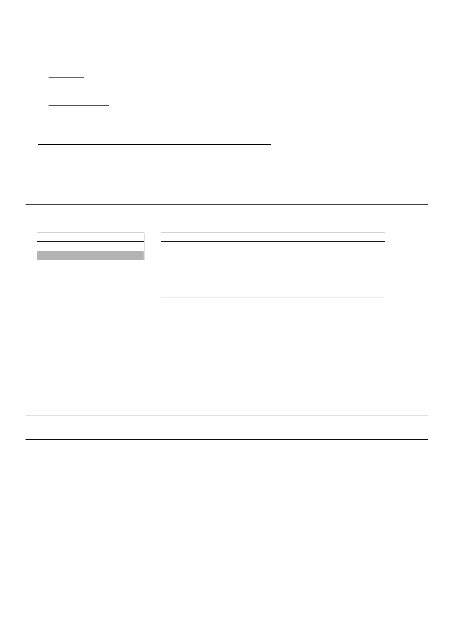
BACKUP USB BACKUP
USB BACKUP
START TIME 2006 – 12 – 01 21 : 35 : 00
DISK BACKUP END TIME 2006 – 12 – 01 21 : 45 : 00
AVAILABLE SIZE 1.460 GB
CHANNEL z 01 z 02 X 03 X 04
HDD NUM HDD-MASTER-1
BACKUP TO USB START
The submenu items are described below:
‧ START TIME
Select the start time of the backup.
‧ END TIME
Select the end time of the backup.
‧ AVAILABLE SIZE
Display the available capacity in the inserted USB flash drive.
‧ CHANNEL
-25-
Page 30
MENU FUNCTION
Select channels by pressing “ENTER” button to change the symbol in front of the channel number.
Symbol “X” means that this channel is not selected to backup.
Symbol “●” means that this channel is selected to backup.
‧ HDD NUM
Press “ENTER” to select the HDD containing the data you need.
‧ BACKUP TO USB
Press “ENTER” to start copying the chosen data to the USB flash drive.
2) DISK BACKUP (CD writer backup function is only for Model 1 & 5)
Before making disk backup, please check if the type of your CD is CD-R. The maximum number of backup files in the
CD is 41.
Note: During the backup process, a file player will also be copied into your CD, and you will see a message
“BACKUP PLAYER” shown on the screen.
Move the cursor to “BACKUP”, and press ”ENTER”. You will see a similar screen as the following:
BACKUP DISK BACKUP
USB BACKUP START TIME 2006 – 12 – 01 20 : 35 : 00
DISK BACKUP
END TIME 2006 – 12 – 01 23. : 35 : 00
AVAILABLE SIZE 600 MB
CHANNEL z 01 z 02 X 03 X 04
HDD NUM HDD-MASTER-1
BACKUP TO DISK START
The submenu items and their functions are the same as USB BACKUP except for “BACK TO DISK” item.
The process below describes how to make a disk backup:
‧ Press “EJECT” button to open the disk tray. Put the CD into a CD-RW drive, and press “EJECT” button again to
close the disk tray.
‧ Go to “DISK BACKUP” menu, and set the start time, end time, channels and HDD.
‧ Move the cursor to “BACKUP TO DISK”, and press “ENTER” to start backup.
While CD backup is processing, users will see the backup completed percentage on the screen.
Note: During the backup process, a file player will also be copied into the CD, and you will see a message
“BACKUP PLAYER” shown on the screen.
‧ After CD backup is completed, “DISK BURN FINISH” will be prompted on the screen. Press “EJECT” button to eject
the CD tray and get the CD.
‧ Put the CD into the CD-ROM drive of your PC. Double click the file to convert it into “AVI” format. Play the converted
file in your PC to see if the backup is successful.
Note: The supported PC operation systems are Windows 2000 and Windows XP.
-26-
Page 31

6.4.9 HDD Info
In this menu list, you can view the remaining capacity of all the connected HDDs in this device.
Move the cursor to “HDD INFO”, and press ”ENTER”. You will see a similar screen as the following:
MENU FUNCTION
ADVANCE
CAMERA
DETECTION MASTER-1 368 SLAVE-1 NO HDD
DISPLAY MASTER-2 NO HDD SLAVE-2 NO HDD
ALERT EXT-001 NO HDD EXT-002 NO HDD
REMOTE EXT-003 NO HDD EXT-004 NO HDD
SYSTEM EXT-005 NO HDD EXT-006 NO HDD
NETWORK EXT-007 NO HDD EXT-008 NO HDD
BACKUP EXT-009 NO HDD EXT-010 NO HDD
HDD INFO
EVENT LOG
HDD NUM HDD SIZE HDD NUM HDD SIZE
HDD INFO
6.4.10 Event Log
In this menu list, you can view all the event information (event type, time and channel) or clear all log records.
Move the cursor to “EVENT LOG”, and press ”ENTER”. You will see the following options:
ADVANCE
CAMERA
DETECTION NET LIST
DISPLAY SYSTEM LOG
ALERT OTHERS
REMOTE CLEAR ALL
SYSTEM
NETWORK
BACKUP
HDD INFO
EVENT LOG
VLOSS LIST
EVENT LOG
The submenu items are described below:
1) VLOSS LIST
Show the information of the video loss time.
2) NET LIST
Show the information of the net login time.
3) SYSTEM LOG
Show the error codes for system errors. For the meaning of each error code, please see the following list:
Error Code in “SYSTEM LOG”: Meaning:
1) SYS ERR 01-YYY #define SYS_ERR_AV087_ERR 1) Compression error
YYY=000 Audio chip error
YYY=001- AV087 Chip for CH1-4 error
2) SYS ERR 02-XXX #define SYS_ERR_AV087_BUF_FULL Buffer is full
3) SYS ERR 03-XXX #define SYS_ERR_AV087_BUF_EMPTY Buffer is empty
4) SYS ERR 04-XXX #define SYS_ERR_IDE_ERR IDE interface error
5) SYS ERR 05-XXX #define SYS_ERR_SCAN_DISK Disk scanning error
6) SYS ERR 06-XXX #define SYS_ERR_TOP_FAT_ERR File system error
7) SYS ERR 07 (including 08, 09, etc.)-XXX #define HDD error
4) OTHERS
Show the information of “power on / off”, “unlock” and “reset to default” time.
5) CLEAR ALL
Clear all event log lists.
-27-
Page 32

MENU FUNCTION
6.5 Search
In this menu list, you can view the time for all the events recorded under different situations and play the file you want,
or search any specific events by event or time and directly play the file you find.
Press “SEARCH” button on the front panel. You will see the following screen:
SEARCH
HDD-MASTER-1
FULL LIST
RECORD LIST
SYSTEM LIST
ALARM LIST
MOTION LIST
EVENT SEARCH
TIME SEARCH
The submenu items are described below:
1) HDD-MASTER-1
Press “ENTER” to change to the HDD you want if there are more than 1 HDD in your DVR.
2) FULL LIST
Show the time list for all types of the recorded files. The capital letters stand for the following:
R: RECORD / S: SYSTEM / A: ALARM / MS: MOTION / T: TIMER
3) RECORD LIST
List the time of manual-recorded files.
4) SYSTEM LIST
List the time of system-recorded files.
Under the manual recording mode, the DVR system will save one recorded file every one hour.
5) ALARM LIST
List the time of alarm-trigger-recorded files.
6) MOTION LIST
List the time of motion-trigger-recorded files.
7) EVENT SEARCH
Move the cursor to “EVENT SEARCH” and press ENTER button to search and directly playback the recorded files by
the specific time period (YEAR / MONTH / DAY / HOUR / MIN), channel, HDD, and event type (motion / alarm triggered
recording).
8) TIME SEARCH
Move the cursor to “TIME SEARCH” and press ENTER button to search the recorded files by the specific time period
(YEAR / MONTH / DAY / HOUR / MIN).
Note: The file found will be played with the fast speed.
-28-
Page 33

MENU FUNCTION
6.6 Additional Operation
6.6.1 Key Lock and Unlock
‧ Key Lock On: Press “MENU” + “ENTER” buttons on the DVR front panel to lock keys.
‧ AUTO KEYLOCK: Set the time-out after which the key lock function is activated (Never / 10 SEC / 30 SEC / 60 SEC).
Please refer to section “6.4.6 System” at page 22.
‧ Key Lock Off: Enter the DVR password to exit “Key Lock” mode.
Note: For the password setting, please refer to the section “3.7 Password and User Name Setting” at page 11.
6.6.2 Switch NTSC / PAL System
‧ Switch to NTSC System ( or POWER + ):
Press “POWER” button on the DVR front panel to shutdown. Then, press and hold “ “ first, and press “POWER” to
switch to NTSC system. (Press the buttons until the monitor shows video images.)
‧ Switch to PAL System ( or POWER + ):
Press “POWER” button on the DVR front panel to shutdown. Then, press and hold “ “ first, and press “POWER” to
switch to PAL system. (Press the buttons until the monitor shows video images.)
Note: The DVR will automatically detect PAL/NTSC system. But you can also manually switch between PAL
and NTSC systems.
6.6.3 Upgrade
Note: Do not disconnect the power of your DVR while the upgrade process is in progress, or the DVR
functions may not work normally or be unable to use.
(1) Firmware / Multilanguage OSD Upgrade
‧ Use USB to upgrade:
Please format the USB memory device as FAT 32 format first. Get the upgrade files from your distributor. Save the
upgrade files in your USB device (do not change the file name). Go to “MAIN MENU” → “SYSTEM” → “UPGRADE”,
and press “ENTER” button. Select “YES”, and press “ENTER” button again to confirm upgrade. For detailed
instructions, please refer to section “6.4.6 System” at page 22.
‧ Use AP software to remotely upgrade:
In the login page of the AP software, enter the user name, password, IP address and port of the DVR. Then, press
“ ” button to upgrade DVR firmware or OSD language files. The provided firmware and OSD files should be saved
at PC first.
(2) AP and JAVA Software Upgrade
‧ Type the IP address where your DVR is located into the URL address box, and press “Enter” to login the AP.
‧ For detailed description, please refer to section “7.6 Operation via IE Browser” at page 48.
6.6.4 Audio Backup and Playback
If you want to backup images with audio, please connect the cameras to the correct channels. For model 1,2 & 5,
the audio channels are CH1 – CH2. For model 3 & 4, the audio channels are CH1.
Note: For detailed camera connection, please refer to section “3.2 Camera Connection” at page 8.
For detailed backup instruction, please refer to section “6.4.8 Backup” at page 25.
-29-
Page 34

SLOW
MENU FUNCTION
ZOOM
To select live or playback sounds of the 2 audio channels, please press these two buttons
AUDIO
or on the
DVR front panel at the same time. For detailed playback instructions, please refer to section “4.2 Playback” at page 14.
For detailed playback instructions on the remote PC side, please refer to section “7.4 Playback Operation” at page 35.
6.6.5 PTZ Camera Setup and Control
‧ PTZ connection: Please refer to section “3.2.2 PTZ” at page 8.
‧ PTZ ID, protocol, baud rate setting at the DVR side: Please refer to section “6.4.5 Remote” at page 22.
‧ PTZ ID, protocol, baud rate setting at the remote AP software side:
Please refer to section “(1) Device” at page 39 (AP software system configuration).
‧ PTZ control at DVR side:
SEQ.
Press these
P.T.Z
or two buttons on the DVR front panel at the same time to enter / exit the PTZ control mode.
In the PTZ control mode, press "+" button to zoom in, press "-" button to zoom out, and press "UP”, “DOWN”, “LEFT”
or “RIGHT" buttons on the DVR front panel to adjust the PTZ angle.
‧ PTZ control at AP software side: Please refer to section “7.3.2 PTZ Camera Control Panel” at page 34.
6.6.6 R.E.T.R. Setup (For Model 5 only)
Before activating the R.E.T.R. function, please set the motion detection area first.
(1) Setup Motion Detection Function:
Activate motion detection function and setup the motion detection area and sensitivity. Please refer to section “6.4.2
Detection” at page 18, or section “(2) Detection” at page 40 (AP software system configuration).
(2) Activate the R.E.T.R. Function:
‧ From DVR front panel:
Press ”Menu” and “-” buttons on the DVR front panel at the same time. R.E.T.R. function will be activated 3 / 5 / 10
minutes later. For detailed instructions, please refer to section “6.4.6 System”. A message “R.E.T.R. ON” will be shown
on the screen (in white text), and after the RETR function is activated, the message “R.E.T.R.” shown on the screen will
turn to red.
‧ From AP software at remote PC/NB side:
Press “R.E.T.R.” button on the AP control panel to activate the R.E.T.R. function immediately. Please refer to section
“7.3.1 DVR Control Panel”.
‧ From IR transmitter:
Press “R.E.T.R.” button on the IR remote control to activate the R.E.T.R. function for 3 / 5 / 10 minutes later. Please
refer to the IR transmitter manual.
(3) Turn off the R.E.T.R. Function:
‧ From DVR front panel:
Press any key (except “ ” or “POWER” button) and enter the password to turn off the RETR function.
‧ From AP software at remote PC/NB side:
Press “R.E.T.R.” button on the AP control panel again to turn off the R.E.T.R. function.
‧ From IR transmitter:
Press any key (except “POWER” button) and enter the password to turn off the RETR function.
-30-
Page 35

LICENSED SOFTWARE AP
7. LICENSED SOFTWARE AP
7.1 Installation
1) Install the software:
Place the attached licensed software AP disk into the CD-ROM drive, and install the application programs into your
PC (Including AP and JAVA programs). After setup, users will see an AP shortcut icon on the desktop.
For the latest software AP, please check with your distributor, or download from the Internet. Please refer to section
“(2) AP and JAVA Software Upgrade” at page 29, or section “7.6 Operation via IE Browser” at page 48.
2) Local Network Connection:
Connect your DVR to PC via RJ45 network line. The default DVR IP is “192.168.1.10”, and default user name and
password are both “admin”. Users should set PC’s IP address as “192.168.1.XXX ” (1~255, except 10) in order to make
the PC and DVR under the same domain.
Double click " " to enter the login page. Key in default IP address (192.168.1.10), username (admin), password
(admin) and port (80) in the login page.
3) Network Setting
After connecting to the DVR with local LAN, you can modify the network settings in the DVR or in “SYSTEM
CONFIG” menu of the software AP.
For the static IP network type, please refer to section “3.6.1 STATIC IP” at page 9. For the dynamic IP network type
(PPPOE or DHCP), please refer to section “3.6.3 Dynamic IP - PPPOE” at page 10 and section “3.6.4 Dynamic IP -
DHCP” at page 11. For detailed DDNS apply, please refer to section “3.6.2 DDNS Apply” at page 10.
4) User Name and Password Setting:
For detailed user name and password setting, please refer to section “3.7.2 Remote Login Password and User
Name Setting” at page 12.
7.2 Login Panel
After setting up the network information, remote login user name and password, double click " " on the
desktop to enter the software AP login page, and key in "Username", "Password", "IP” (IP address for static IP or host
name for dynamic IP) as well as "Port". Then, click the green button to connect to the DVR.
The AP login icon explanations are as following:
ICON EXPLANATION ICON EXPLANATION
Press this button to add a
new IP address into the IP
Address Book
Search
Player
address book, or choose any
preset IP address to access
the software AP software.
Search available DVR IP
addresses in the local area
network and modify the
network setting of the DVR.
Press this button to access
and play the latest recorded
file that are saved in your PC.
Copy
Upgrade Firmware
Press this button to copy all
the software installation files,
so users can keep all the
settings of the video web
server for next software
installation on other PCs.
Press this button to upgrade
DVR firmware or OSD
language files. The provided
firmware and OSD files
should be saved at PC first.
Note: The version of the licensed software AP will be shown on the login page.
-31-
Page 36
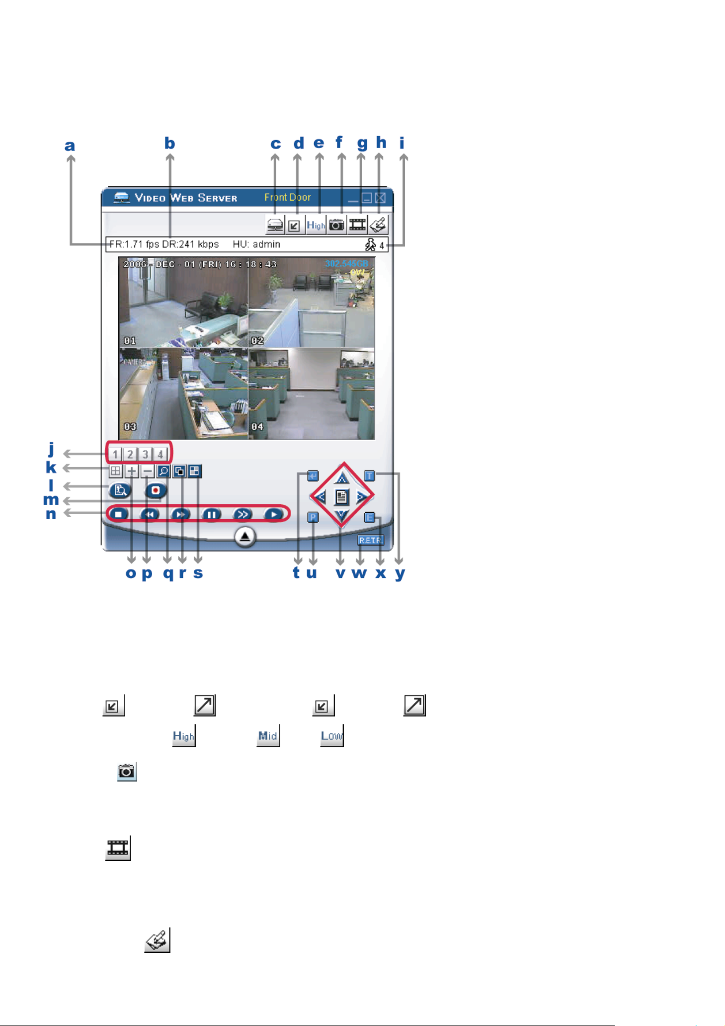
7.3 Control Panel
7.3.1 DVR Control Panel
LICENSED SOFTWARE AP
a. Data Transfer Rate
b. Image Transfer Rate Per Second
c. Connect / Disconnect
d. Resolution:
NTSC: 320 × 228; 640 × 450; PAL: 320 × 276; 640 × 552
e. Image Quality (High , Medium , Low )
f. Snapshot :
Press this button to take a snapshot of the image which will be saved in the specified destination set in “SYSTEM
CONFIG” → “FIL E PATH” → “Snapshot Path”.
g. Record :
Press this button to start recording, and press this button again to stop recording. The recorded files will be saved
to the specified path on the PC. Each recorded file can be up to 18,000 frames. When the recorded file is full, a
new-recorded file will be saved as the second file. If the HDD space is less than 200MB, the program will stop
recording.
h. System Config : Press this button to enter the setting page of the licensed software AP.
-32-
Page 37
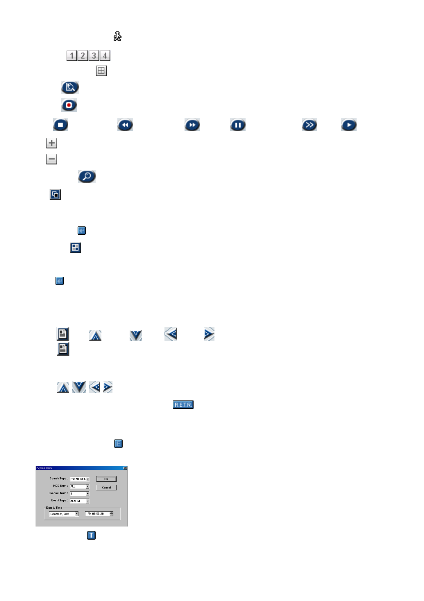
LICENSED SOFTWARE AP
i. Number of Online Users
j. CH 1 ~ 4
k. 4 Channel Display
l. Search : Press this button to enter the DVR search menu.
m. Record
n. Stop / Fast Rewind / Fast Forward / Pause / Slow Playback / Play
o. +
p. -
q. Digital Zoom : Digital zoom in/out
r. Set :
Press this button to change the position of the channel display.
Press “UP”, “DOWN”, “LEFT”, “RIGHT” buttons to select the channel you would like to change.
Press “+” or “-” select the channel you would like to show.
Press “Enter ” button to confirm the setting.
s. Sequence :
Press this button to enter the call monitor function, and press again to exit from the call monitor mode. When any
motion is detected, the monitor will switch to the channel which is motion-triggered.
t. Enter : Press this button to confirm the settings or enter your selection.
u. PTZ Control On / Off:
When the PTZ control is turned on, users could select the PTZ device, and press “OK” button to enter the PTZ
control AP screen. (Press “ESC” to exit from the PTZ control AP screen and return to the DVR control AP screen)
v. Menu / Up / Down / Left / Right :
Press button to enter the menu / to confirm the selection and return to the upper menu / exit the menu
mode. (Via software AP or IE browser, you can remote login to the DVR, but if the user name and password that
you used is not the supervisor level, you are not allowed using this function. For detailed user name and
password setting, please refer to “(1) Account” in the section “7.5.4 General” at page 46.)
Press buttons to move the cursor and make the selection.
w. R.E.T.R. (Remote Event Trigger Recording) (For Model 5 only):
Press this button to activate the R.E.T.R function, and press again to exit. When R.E.T.R. is on, users at the
remote PC side will get a real-time alarm sound notification, and the recorded files will be saved to the specified
path on the PC.
x. Search DVR Video Data :
Press this button to show the following window and set data search criteria. The video data found will be played
in the AP view.
y. Turbo ON/ OFF :
To speed up menu selection or the control of the PTZ camera under the software AP, users can activate TURBO
function by clicking this button. Users are allowed to change the turbo steps from 1 to 30.
Ex: If users activate TURBO function and set the value of the turbo step as 3, one mouse-click will function as
clicking 3 times when users press one of the button up/down/left/right.
-33-
Page 38
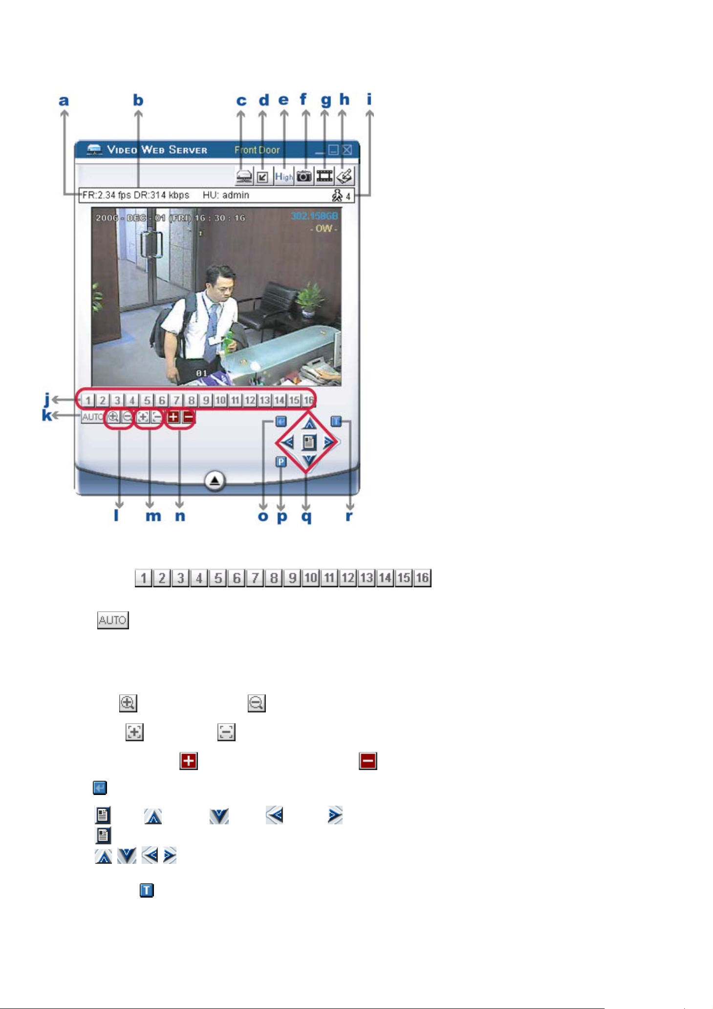
7.3.2 PTZ Camera Control Panel
LICENSED SOFTWARE AP
a ~ j: Same as the DVR control panel a ~ j.
k. Preset 1 ~ 16 :
A preset position is a pre-defined camera view that can quickly and easily been viewed.
l. AUTO :
Press this button to enter the auto pan or sequence mode (depend on the setting in the PTZ menu). In the auto pan
mode, the Live View page will rotate through the selected preset positions, in a set order or in sequence. In the
sequence mode, the Live View page will automatically display the view from preset positions in a set order at set
intervals.
m. Zoom Tele Zoom Wide
n. Focus Near Focus Far
o. Continuously Zoom In Continuously Zoom Out
p. Enter : Press this button to confirm the settings or enter your selection.
q. Menu / Up / Down / Left / Right :
Press button to enter the PTZ menu / to confirm the selection and return the upper menu / exit the menu mode.
Press buttons to move the cursor and make the selection.
r. Turbo ON/ OFF :
To speed up menu selection or the control of the PTZ camera under software AP, users can activate TURBO function
by clicking this button. Users are allowed to change the turbo steps from 1 to 30.
Ex: If users activate TURBO function and set the value of the turbo step as 3, one mouse-click will function as clicking
3 times then when users press one of the button up/down/left/right.
-34-
Page 39
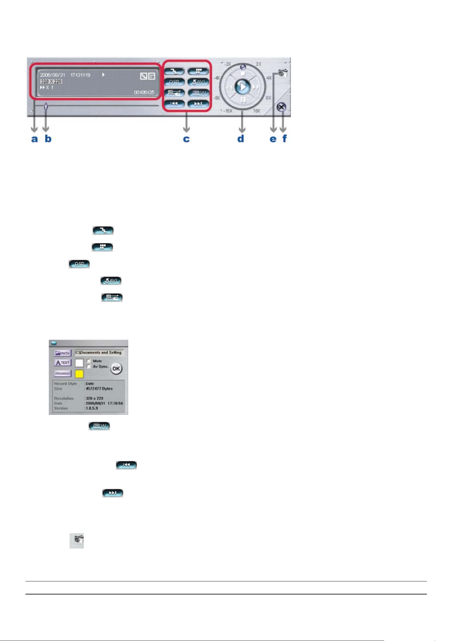
LICENSED SOFTWARE AP
7.4 Playback Operation
7.4.1 AP Playback Functions:
a. Playback Information:
Display the information, such as “Date”, “Time”, “Resolution”, “ Rewind / Forward Speed”, “Status” and “Functions”, etc.
b. Time Progress Bar: Show the playback progress status.
c. Functions:
‧De-interlace : Reduce the vibration of the paused picture.
‧De-blocking : Reduce the video mosaic phenomenon.
‧OSD : Display the OSD of the AP playback window.
‧AVI convertion : Convert the entire recorded file to AVI format.
‧Config. Setting :
Enter AP configuration setting box, and set the file path, text color, and text color of progress status.
* Mute: Play the video only (without audio).
* AV sync. : Play with the audio and video synchronously.
‧Watermark : Proof the authenticity of the backup video.
In the playback mode of the software AP, you can press this button to check the authenticity of the BACKUP VIDEO.
If the BACKUP VIDEO had been altered, the video image will turn to light red and the playback will be paused.
‧Open Previous File : Open the previous backup video.
When users pause the playback, press this button to go to the previous frame.
‧Open Next File : Open the next backup video.
When users pause the playback, press this button to go to the next frame.
d. Playback Control Buttons: Play / Stop / Pause / Fast Rewind / Fast Forward
e. Snapshot :
Press this button to take a snapshot of the current image which will be saved in the specified destination.
f. Close the Player
Note: When users use remote AP manual recording, the watermark function is not supported.
-35-
Page 40
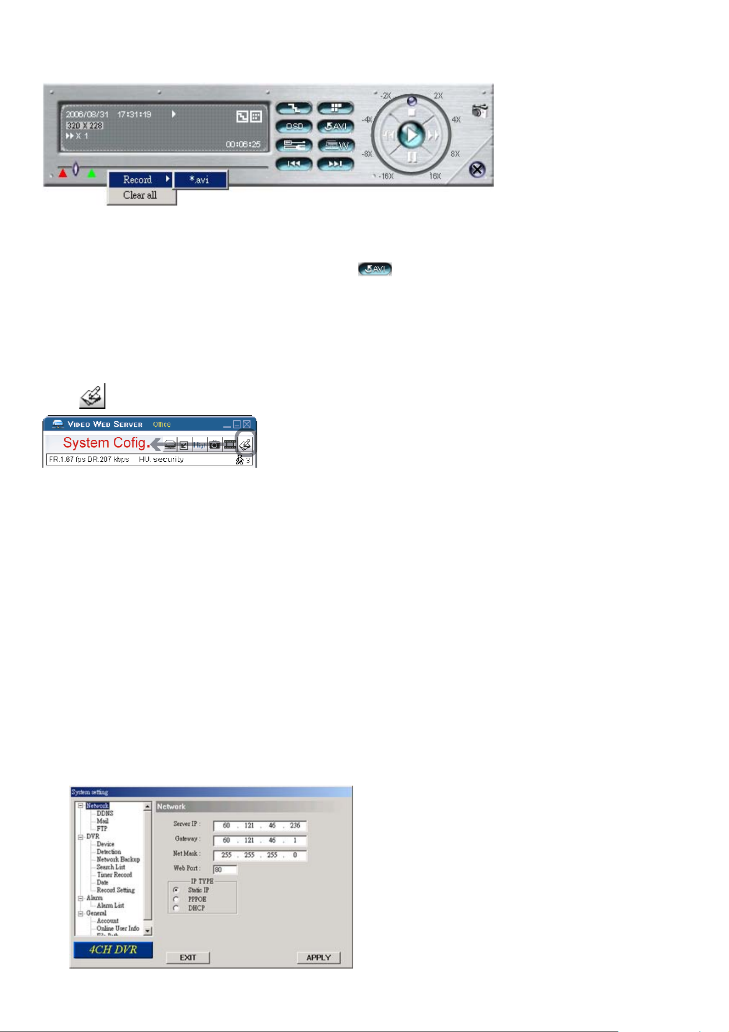
LICENSED SOFTWARE AP
7.4.2 Convert the recorded file to AVI format
The backup file can be played directly in your PC via the supplied licensed software AP, or via other media players (Ex:
Windows Media Player or RealPlayer) after the file is converted to “AVI” format.
To convert the entire recorded file to AVI format, press button.
To snap a video clip, right-click the mouse to set a starting point (▲ red) and click one more time to set an ending
point (▲ green). Then, right-click the mouse to convert to AVI format.
7.5 System Configuration
Press button to enter the AP system setting page.
7.5.1 Network
The network configuration allows the DVR to connect to an LAN or Internet.
PPPoE and DHCP network connection types are required to apply a DDNS service to get a “Hostname” to correspond to a
dynamic IP address. Please refer to section “3.6.2 DDNS Apply” at page 10 for details.
‧ Web Port:
The DVR can be viewed over the network with the licensed software AP or the IE web browser. Typically, the default
TCP port used by HTTP is 80. However in some cases, it is better to change this port number for added flexibility or
security. The valid web port number ranges from 1 to 9999.
‧ Static IP:
Computers are communicated and recognized by their own unique IP addresses over the Internet. “Static IP”
provided by your ISP (Internet Service Provider) means the IP address of the computer is fixed.
In this “Network” menu, choose “Static IP”, and enter the “Server IP”, “Gateway”, “Net Mask” and “Web Port”. Then,
press “APPLY” button to confirm.
-36-
Page 41
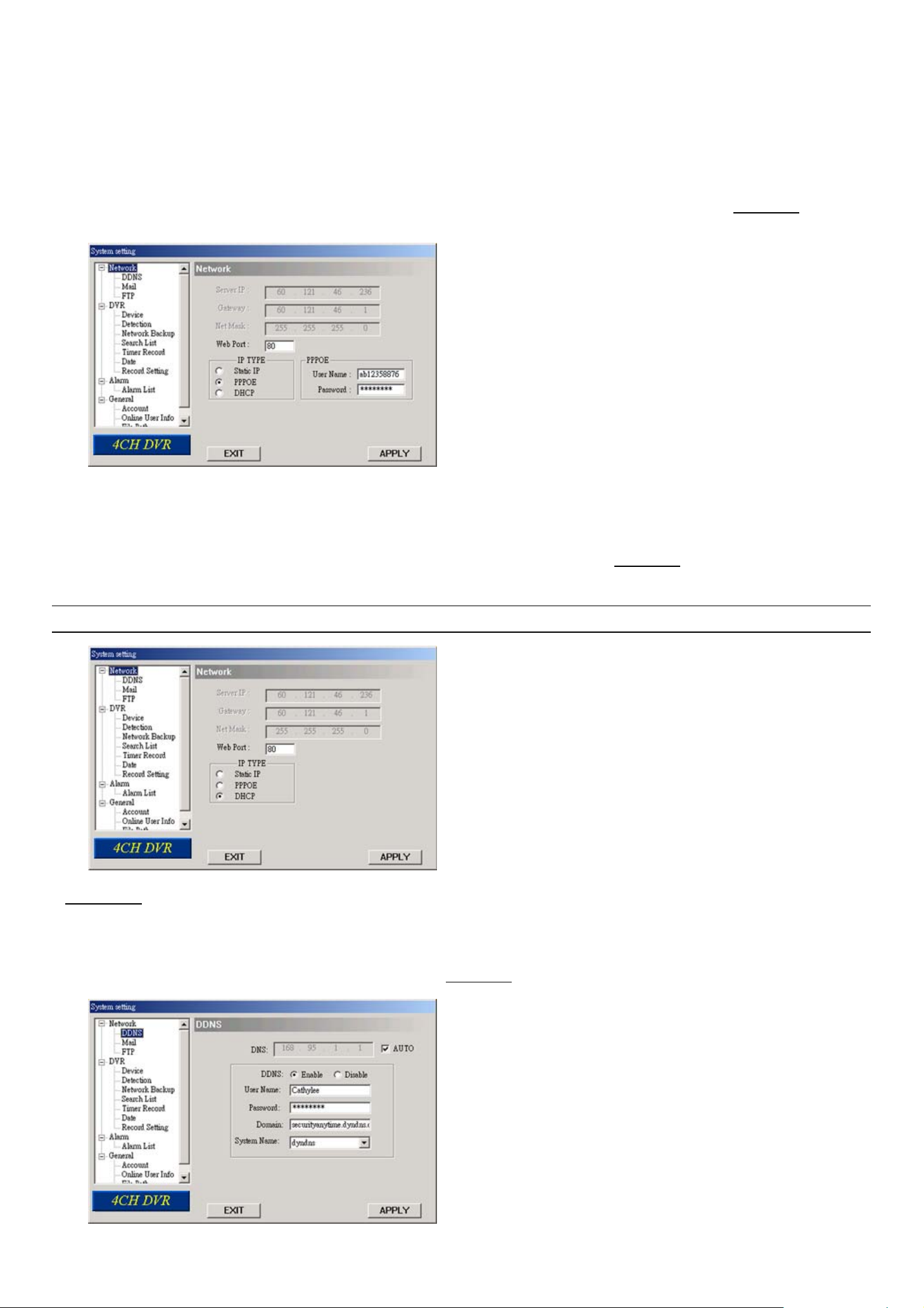
LICENSED SOFTWARE AP
‧ PPPOE
PPPOE stands for Point-to-Point Protocol over Ethernet. Users can easily have Internet services as long as
they’re ready for the following things: 1) Insert an Ethernet card into the PC. 2) Obtain ADSL service via any ISP. 3)
Obtain and install PPPoE software CD.
In this “Network” menu, choose “PPPOE” and enter the “User Name”, “Password” provided by your ISP (Internet
Service Provider) and “Web Port”. Then, select “Network” → “DDNS” to set DDNS settings (see “(1) DDNS” at page
37 for details). When all the settings are completed, press “APPLY”.
‧ `DHCP:
This DHCP function needs to be supported by a router or cable modem network with DHCP services. Choose
“DHCP” IP type. Then, select “Network” → “DDNS” to set DDNS settings (see “(1) DDNS” at page 37 for details).
When all the settings are completed, press “APPLY”.
Note: Some router brands may need to restart the DVR to get the IP address.
(1) DDNS
You need to apply a DDNS account before setting PPPoE or DHCP connection. DDNS is a service for transforming
the dynamic IP corresponding to a specific “Hostname”. Go to a website which provide free DDNS services and apply a
“Hostname”. For DDNS setup, please refer to the section “(1) DDNS” at page 37.
-37-
Page 42
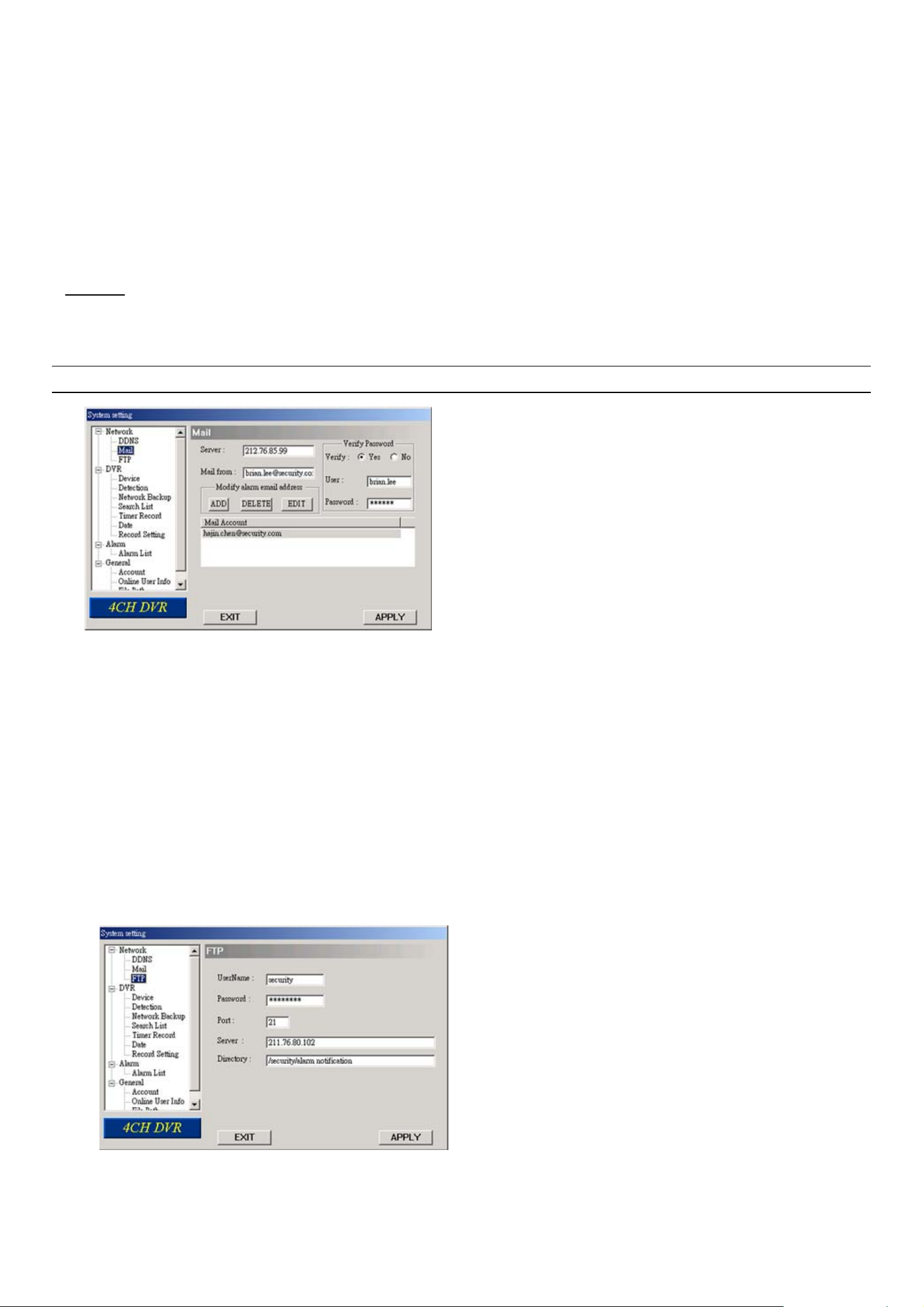
LICENSED SOFTWARE AP
‧ Enable DDNS Function:
a. DDNS: Choose “Enable”.
b. User Name: Type your DDNS account.
c. Password: Type your DDNS password.
d. Domain: Type the “Host Name” you applied previously (EX: securityanytime.dyndns.org).
e. System Name: Choose the DDNS server where you applied the domain name (EX: dyndns).
f. Auto: If you select “DHCP” option in “Network” menu, then “AUTO” option will be shown in this menu.
g. You can check the “AUTO” option to automatically assign the IP address.
(2) Mail
If the e-mail notification function is activated, the DVR will send an e-mail notification to the specified recipients once
alarm-trigger or motion-trigger recording happened. Please enable the function of e-mail notification in the “Alarm” menu first.
Note: Users can assign up to 4 mail accounts for E-mail notification.
‧ Mail Notification Function:
a. Add the recipients’ E-mail accounts in “Mail Account” column.
Please type the entire E-mail address in the “Mail from” column to ensure E-mails will not be blocked by SMTP.
For detailed information (SMTP server, username and password), please check with your E-mail service supplier.
b. Some mail servers are required to verify the password. Please enter the “user name” and “password”.
c. After finishing the setting, press “APPLY” to confirm.
(3) FTP
If the FTP notification function is activated, the DVR will upload the captured images to the specified FTP site once
alarm-trigger or motion-trigger recording happened. Please enable the function of FTP notification in the “Alarm” menu first.
‧ FTP Notification Function:
a. Enter the detailed FTP information.
b. After finishing the setting, press “APPLY” to confirm.
-38-
Page 43
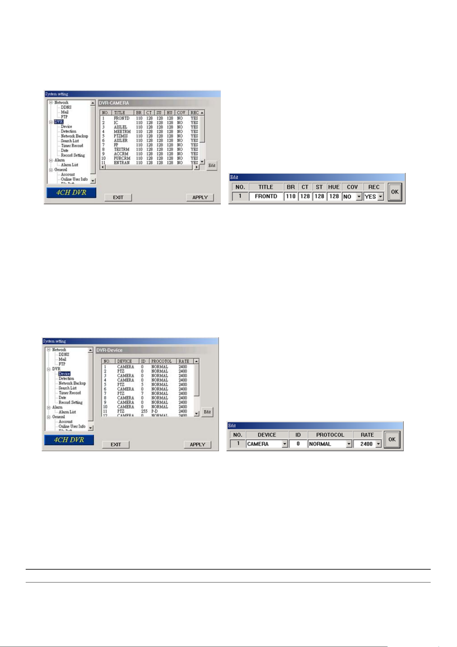
LICENSED SOFTWARE AP
7.5.2 DVR
Each camera channel can be adjusted independently. Select the desired camera channel and press “Edit” to enter the
setting box.
‧ DVR-Camera Function:
a. Title: Enter the camera channel name up to 6 characters.
b. Adjustment: Adjust the BR (brightness) / CT (contrast) / ST (saturation) / HUE / COV / REC values of a camera.
c. After setting, press “OK” and then press “APPLY” button to confirm.
(1) Device
Select the device type (CAMERA / PTZ) according to the connected cameras for each channel. Press “Edit” to enter
the setting box.
‧ The submenu items are described below:
a. Device Type: Choose either normal camera or PTZ camera.
b. ID No.: Set the ID number (0 ~ 255) of the installed external PTZ device.
c. Protocol Type: Choose “NORMAL” protocol for our own brand camera. Choose “P-D” protocol for PELCO-D
protocol camera.
d. Baud Rate: Set the baud rate of each channel (2400, 4800, 9600, 19200, 38400, 57600, 115200).
e. After setting, press “OK” and then press “APPLY” button to confirm.
Note: This function can also be setup at the DVR side, please refer to section “6.4.5 Remote” at page 22.
-39-
Page 44
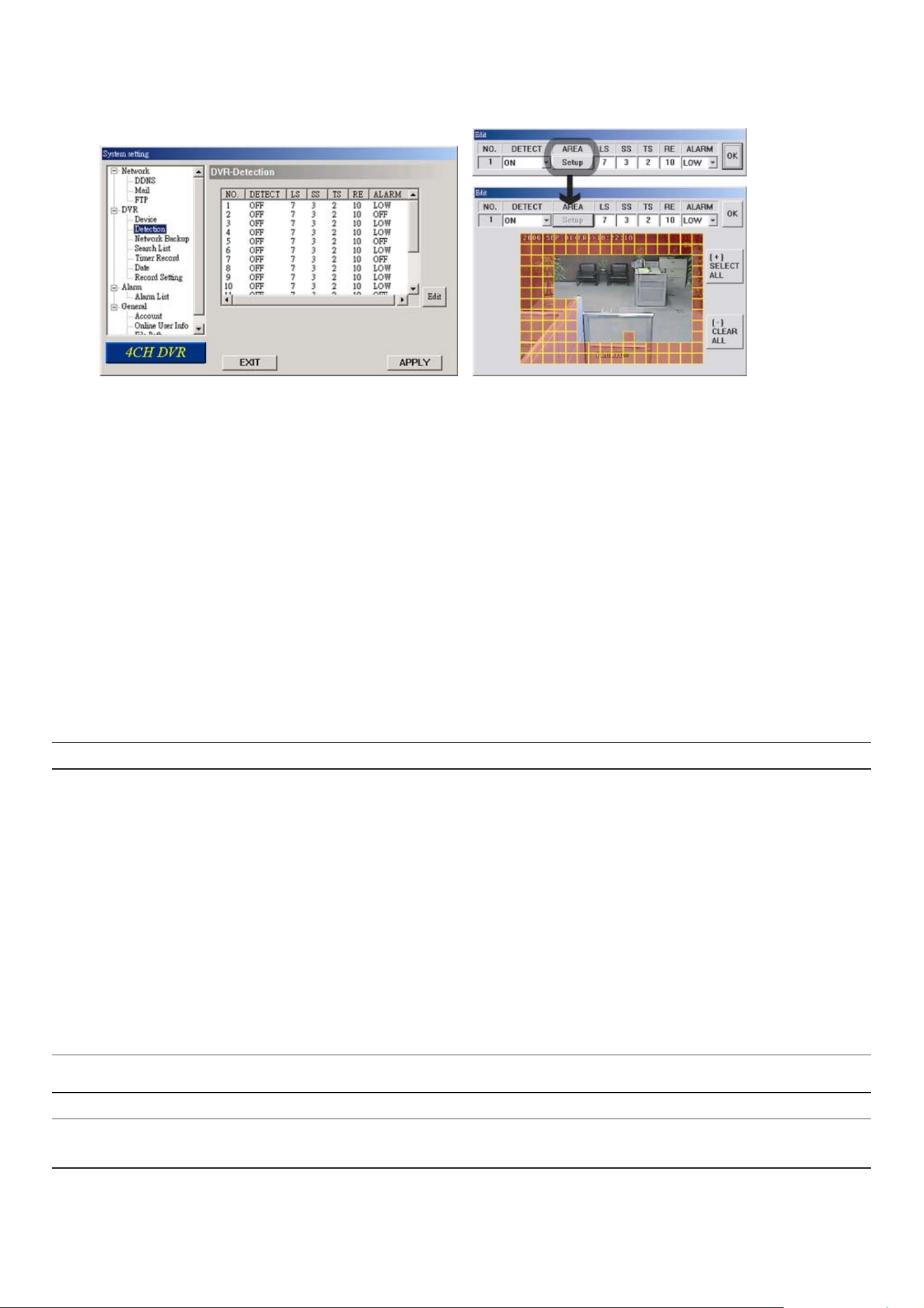
(2) Detection
Select the desired channel, and press “Edit” button to enter the motion detection sensitivity and area-setting page.
‧ The submenu items are described below:
LICENSED SOFTWARE AP
a. DETECT (motion diction):
Select motion detection function ON / OFF.
b. AREA (motion detection area):
Set the motion detection area by selecting the area grids with your mouse. Pink blocks represent the area that is
not being detected while the transparent blocks are the area under detection.
Press “-” to set the whole area under detection.
Press “+” to set the whole area undetected.
b. Motion Detection Sensitivity:
Set the detection sensitivity in 4 different adjustable factors (LS / SS / TS / RD).
c. Alarm:
Select LOW / HIGH for the alarm polarity.
d. After setting, press “OK” and then press “APPLY” button to confirm.
Note: This function can also be setup at the DVR side. Please refer to section “6.4.2 Detection” at page 18.
(3) Network Backup
You can backup the recorded data from the DVR directly to your PC and CD via the network. The backup file can
be played directly in your PC via the supplied licensed AP, or via other media players (Ex: Windows Media Player or
RealPlayer) after the file is converted to “AVI” format.
‧ Enter the backup information:
If you want to make a backup to a CD, please check “Copy to CD”.
If you want to view the backup image while the backup is processing, please check “Dynamic Download”.
After entering the backup information, press "Start" button to proceed the backup process.
Note: For CD backup, please install “NERO” CD burning program to your PC first.
Note: During the file backup process, users can still see the live image at the same time. And the maximum
size per file for Network Backup is 500MB.
-40-
Page 45
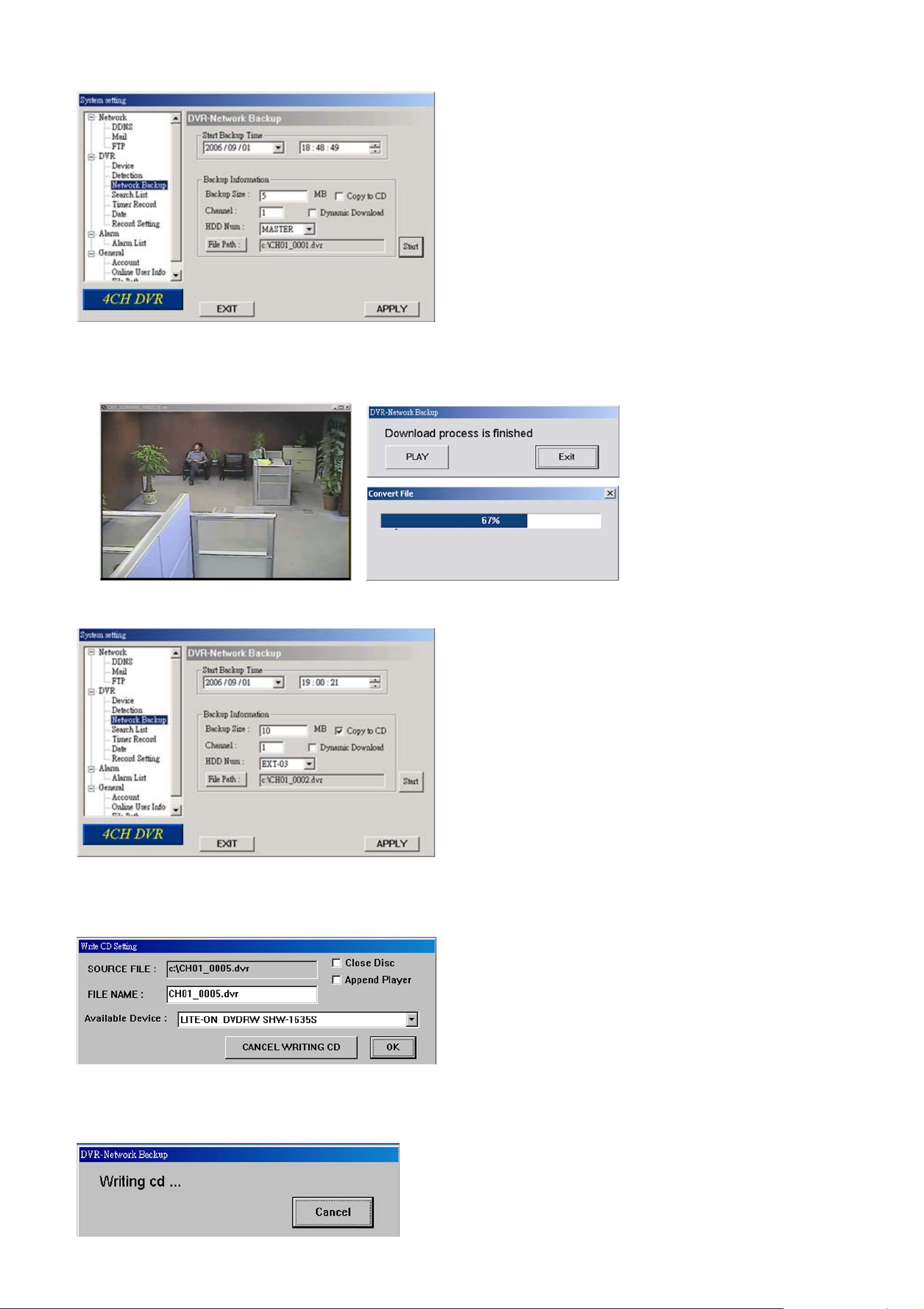
LICENSED SOFTWARE AP
‧ Making backup to your PC:
After pressing “Start”, the backup will be proceeded and a status bar will be displayed. “DVR Network Backup” pop-up
window will show the message “Download process is finished” when the backup is succeeded.
Press “PLAY” button to directly convert and play the file, or “Exit” to quit.
‧ Making backup to a CD:
After pressing “Start”, “Write CD Setting” pop-up window will show on the screen. Choose “Close Disc” when you
don’t want to write any more data to this CD after this burning; choose “Append Player” when you want to play the backup
file on another PC which doesn’t have any available player to play it.
Press “OK” to start making a CD backup, or press “CANCEL WRITING CD” to only make a backup file to your PC.
When CD writing is processing, “DVR-Network Backup” window will show the message “Writing cd …” and a status
bar will show the writing status.
-41-
Page 46
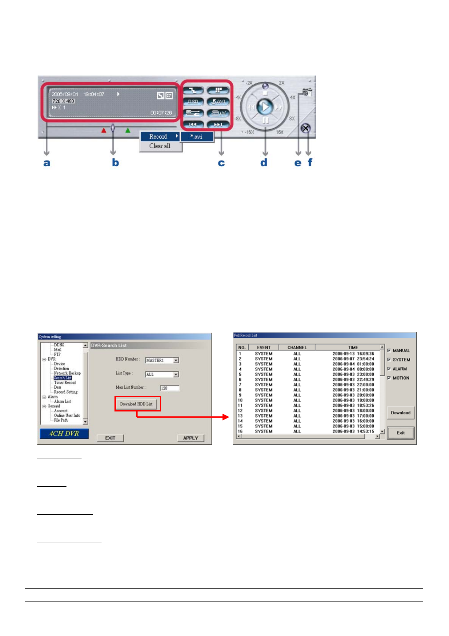
LICENSED SOFTWARE AP
When CD writing is completed, the CD will be ejected, and “DVR Network Backup” pop-up window will show the
message “Download process is finished”. Press “PLAY” button to directly convert and play the file, or “Exit” to quit.
‧ The playback operation are described below:
a. Time Progress Bar
b. Playback Information
c. Functions:
(1) De-interlace (2) De-blocking (3) OSD (4) AVI Conversion
(5) Config. Setting (6) Watermark (7) Open Previous (8) Open Next File
d. Playback Control Buttons: Play / Stop / Pause / Fast Rewind / Fast Forward
e. Snapshot f. Close the Player
For AP playback and AVI conversion details, please refer to section “7.4 Playback Operation” at page 35.
(4) Search List
In “DVR” Æ “Search List”, you can quickly search the event logs from 4 kinds of recording, and directly backup the
event recording of the chosen event log.
‧ HDD Number
Select the HDD from which you want to search recording data in the drop-down menu.
‧ List Type
Select the event type you want to view from the drop-down menu: ALL / MANUAL / SYSTEM / ALARM / MOTION.
‧ Max List Number
Set the maximum number of items in the search list.
‧ Download HDD List
Press “Download HDD List’, and you will see a “Full Record List” shown on the screen.
Highlight the event log you want, and press “Download” to directly go to “DVR-Network Backup” window for video backup.
For the information of network backup, please refer to the section “(3) Network Backup” at page 40.
Tip: You can also quickly go to “DVR-Network Backup” window by double clicking the event log you want.
-42-
Page 47
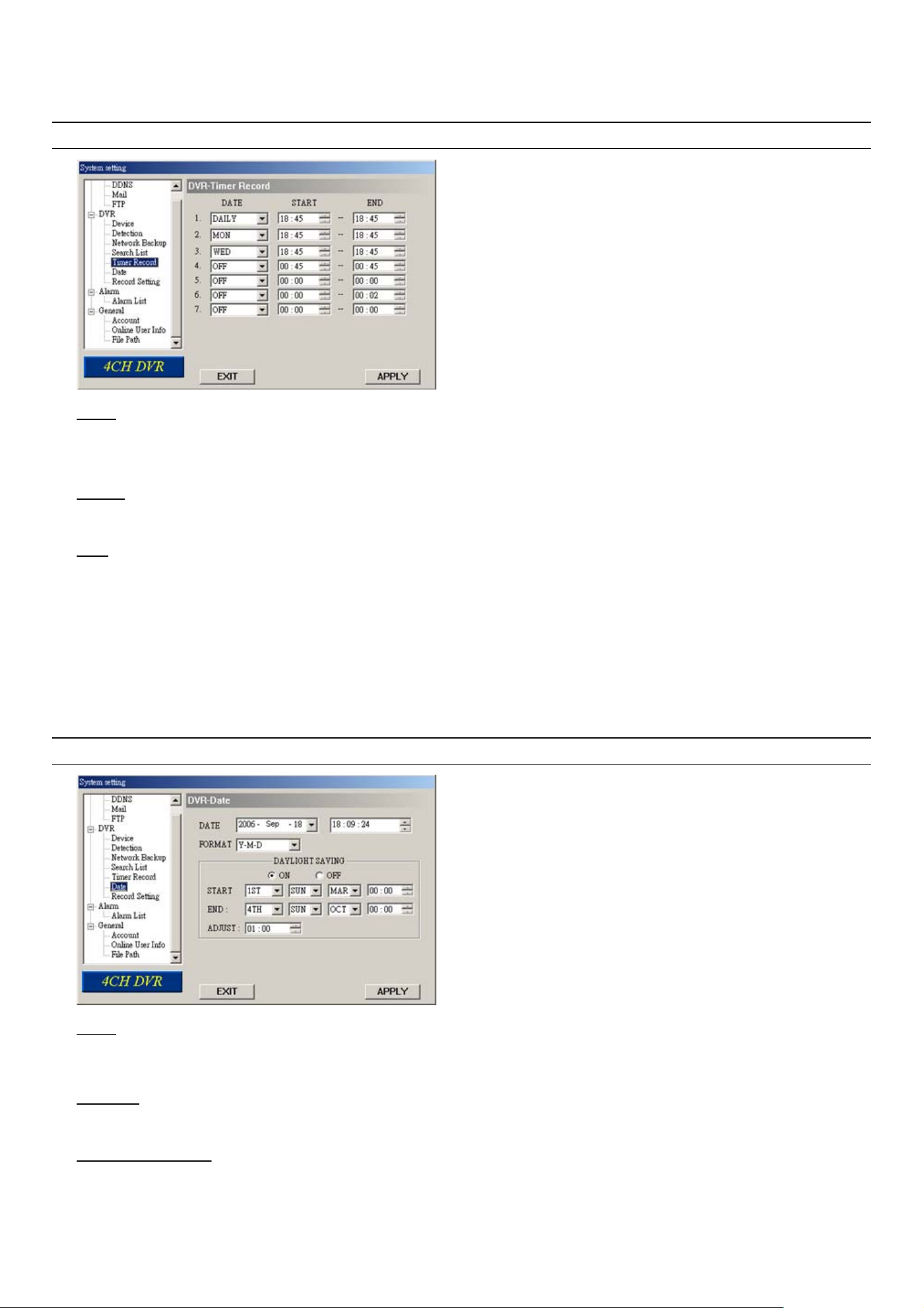
LICENSED SOFTWARE AP
(5) Timer Record
In “DVR” Æ “Timer Record”, you can schedule up to 7 sets of time for recording.
Note: The same settings can also be made in the DVR. Refer to the section “6.2 Timer” at page 17 for details.
‧ DATE
Choose a day from “DATE” dropdown menu. The options are OFF, SUN, MON, TUE, WED, THU, FRI, SAT, MON-FRI,
SAT-SUN and DAILY.
‧ START
Enter the start time of timer recording.
‧ END
Enter the end time of timer recording.
Press “APPLY” to confirm the setup, or “EXIT” to quit without saving.
(6) Date
In “DVR” Æ “Date”, you can set the date for your DVR. Please DO NOT change the date or time when the recording
function is activated. For details, please refer to the section “4.1 Recording” at page 13.
Note: The same settings can also be made in the DVR. Refer to the section “6.3 Date” at page 17 for details.
‧ DATE
Choose the current date from “DATE” drop-down menu and enter the current time.
When you click the drop-down menu, a calendar shown for you to set the current date.
‧ FORMAT
Choose the format for date display from the three options: Y-M-D, D-M-Y and M-D-Y.
‧ DAYLIGHT SAVING
Specify whether to use daylight saving time (ON / OFF) and time period (START / END), and adjust the daylight saving
time in hour (ADJUST).
Press “APPLY” to confirm the setup, or “EXIT” to quit without saving.
-43-
Page 48
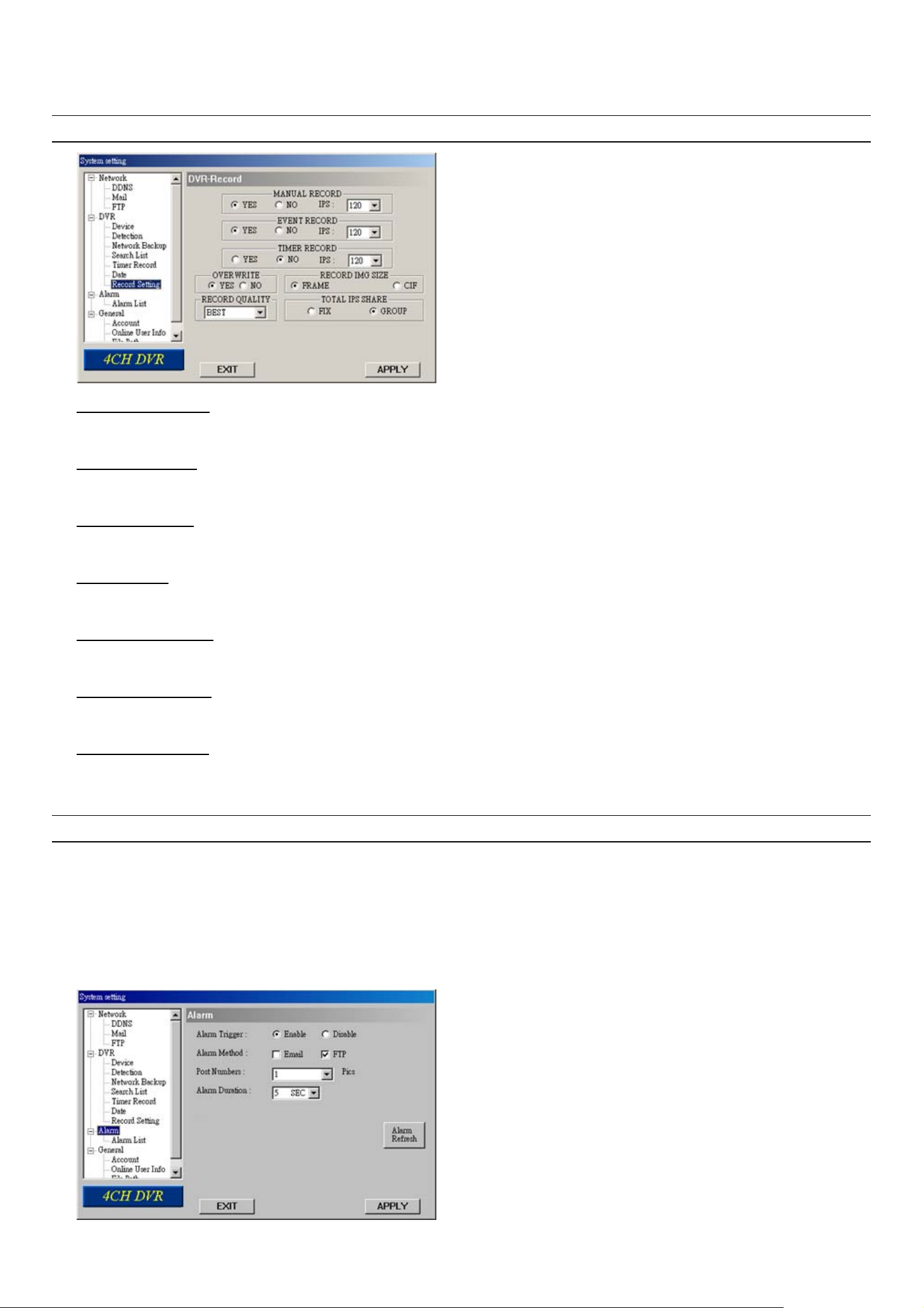
LICENSED SOFTWARE AP
(7) Record Setting
In “DVR” Æ “Record Setting”, you can set DVR record settings.
Note: The same settings can also be made in the DVR. Please refer to the section “6.1 Record” at page 16.
‧ MANUAL RECORD
Specify whether to use manual recording (YES / ON), and set IPS number from the drop-down menu.
‧ EVENT RECORD
Specify whether to user event recording (YES / ON), and set IPS number from the drop-down menu.
‧ TIMER RECORD
Specify whether to user timer recording (YES / ON), and set IPS number from the drop-down menu.
‧ OVERWRITE
Specify whether to overwrite the HDD capacity when the HDD is full (YES / NO).
‧ RECORD IMG SIZE
Choose “FRAME” or “CIF”. This selection will affect the available IPS options of the recording modes described above.
‧ RECORD QUALITY
4 options are available from the drop-down menu: BEST, HIGH, NORMAL and BASIC.
‧ TOTAL IPS SHARE
Choose the total IPS share as FIX or GROUP.
Press “APPLY” to confirm the setup, or “EXIT” to quit without saving.
NOTE: For Model 3 & 4, the total IPS share is always “FIX”. Selecting “GROUP” here is useless.
7.5.3 Alarm
In “Alarm” and its sub-menu “Alarm List”, you can activate the alarm-trigger function, view the detailed information of
alarm events, and play the event recording.
-44-
Page 49
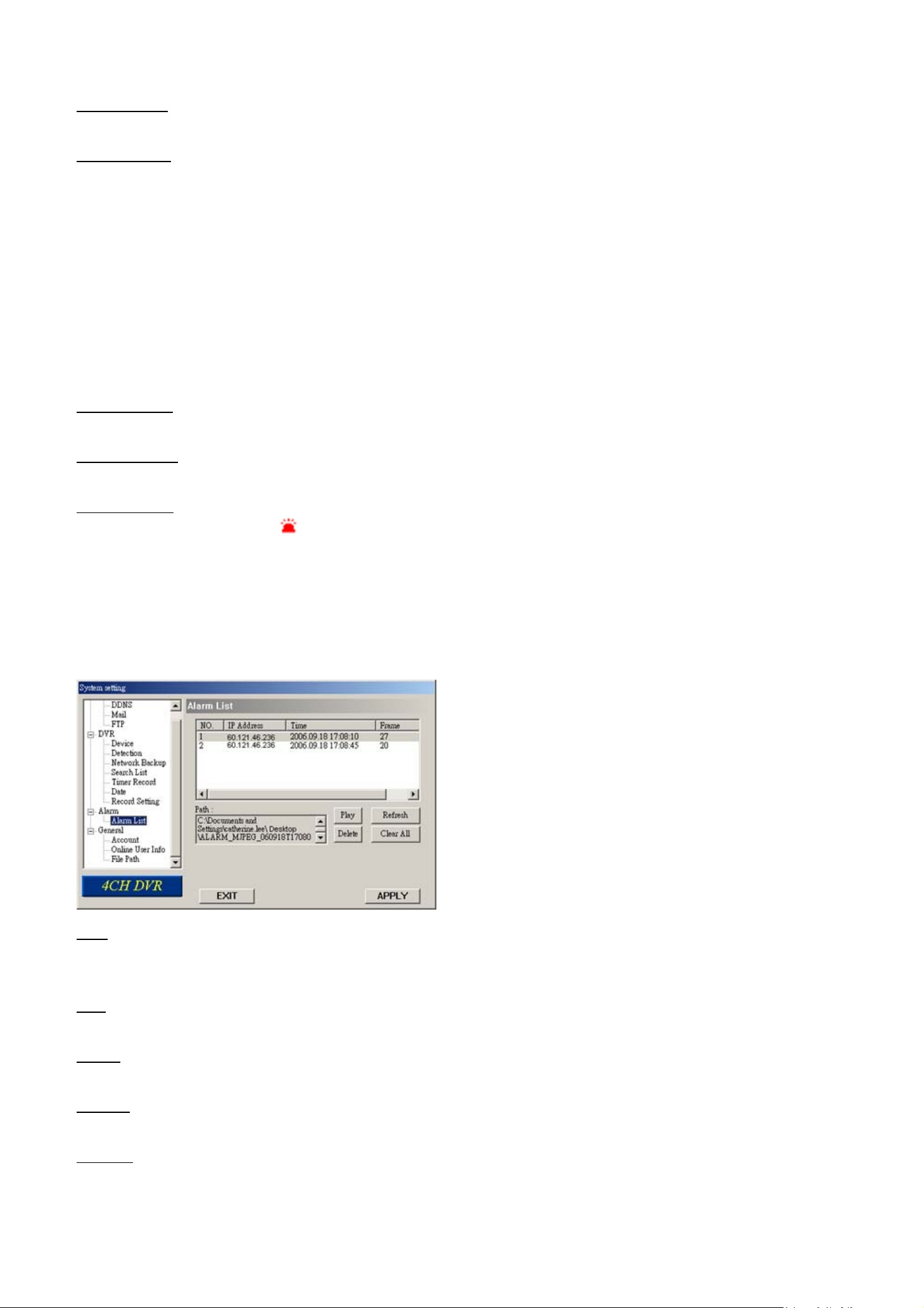
LICENSED SOFTWARE AP
Press “Alarm”, and you will see the following options:
‧ Alarm Trigger
Select to turn the alarm-trigger function on (Enable) or off (Disable).
‧ Alarm Method
Select the notification methods when any alarm is triggered: Email and / or FTP.
a) Email
When this option is checked, MJPEG pictures will be saved in the path assigned in “General” Æ “File Path” Æ
“Snapshot Path” and a copy will also be emailed to the E-mail address assigned in “Network” Æ “Mail” if any alarm is
triggered.
b) FTP
When this option is checked, MJPEG pictures will be saved in the path assigned in “General” Æ “File Path” Æ
“Snapshot Path” and a copy will also be uploaded to the FTP address assigned in “Network” Æ “FTP” if any alarm is
triggered.
‧ Post Numbers
Set the number of MJPEG pictures (1-10) which will be sent with the chosen alarm method(s).
‧ Alarm Duration
Set the duration time of motion trigger recording (5 SEC / 10 SEC / 20 SEC / 40 SEC).
‧ Alarm Refresh
Press to clear the alarm icon “ ” shown on the screen.
(1) Alarm List (For Model 5 Only)
In “Alarm” Æ “Alarm List”, you can view the detailed information of alarm events (IP address, time & frame number),
and see the following options:
‧ Path
Display the location where all the alarm event data will be saved. This path is assigned in “General” Æ “File Path” Æ
“Record Path”.
‧ Play
Choose the event item you want to see, and press “Play” to view the event recording.
‧ Delete
Choose the event item you want to remove, and press “Delete” to remove it.
‧ Refresh
Press “Refresh” to update the alarm list.
‧ Clear All
Press “Clear All” to remove all the alarm event items.
-45-
Page 50
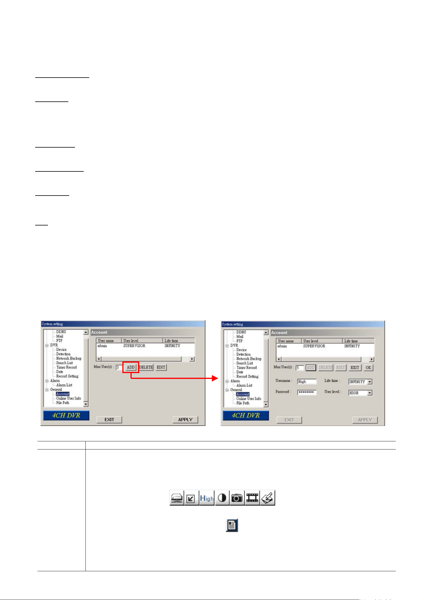
LICENSED SOFTWARE AP
7.5.4 General
In “General” and its sub-menus, “Account”, “Online User Info” and “File Path”, you can view and set up some general
information about this software and your DVR.
‧ Firmware Version
Show the current DVR firmware version information.
‧ Turbo step
To speed up menu selection or the control of the PTZ camera under AP operations, users can activate "Turbo" function
by selecting from the drop-down menu. Users are allowed to change the turbo steps from 1 to 30.
Example: If the value of the turbo step is set to "5", it means that when users press one of the button up/down/left/right,
one click is as clicking 5 times.
‧ Mac address
Show the information of the Mac address.
‧ MAX LOG LIST
Set the maximum number of log list.
‧ Server Log
Press “Server Log” button to enter the server log list window as following. You can filter log types you want to see by
checking or unchecking the log types on the right side.
‧ Title
Name the title which will be shown on the top of the AP live viewer (up to 8 characters).
(1) Account
In “General” Æ “Account”, you can view the current user account information, set the maximum user number,
and add / delete / edit user accounts.
‧ To set the maximum user number, key in the number from 1 ~ 5 in “Max User(s)”.
‧ To create a new account, press “ADD”, and you will see the setting window as the following:
To confirm account creation, press “OK”; to discard the creation, press “EXIT”.
Item Description
Username Set a user name what will be used at AP login page.
Password Set a password what will be used at AP login page.
Life time Select how long this account is allowed to stay online (1 Min / 5 Min / 10 Min / 1 Hour / 1 Day /
INFINITY).
User level
Set the security level of an account. Each level has different permissions for the following functions:
a b c d e f g
SUPERVISOR – Control all the functions and function on the DVR control panel of AP or IE browser.
HIGH – Control all the functions except “g”.
NORMAL – Control only “a”, “e” and “f” functions.
GUEST – Only “a” function can be used. This level is only allowed to watch the live view.
For the function description, please refer to the section “7.3.1 DVR Control Panel” at page 32.
-46-
Page 51
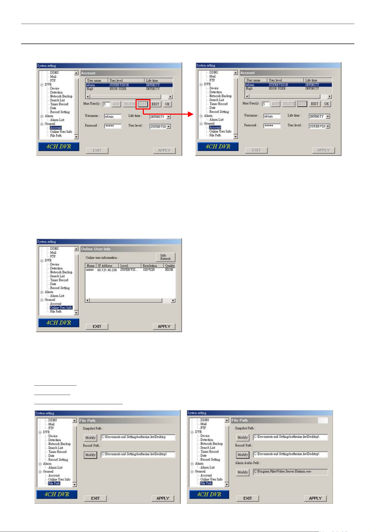
LICENSED SOFTWARE AP
Note: If the number of current accounts already reaches the maximum number, you will not be able to
create an account unless any account is removed.
‧ To edit an account, select one current account you want to modify, and press “EDIT”.
Modify the setting you want to change. To confirm the modification, press “OK”.
‧ To delete an account, select one current account you want to remove, and press “DELETE”. The selected
account will be removed and this operation cannot be recovered.
(2) Online User Info
In “General” Æ “Online User Info”, you can view the current online user account information. This view can be
updated by pressing “Info Refresh” button.
(3) File Path
In “General” Æ “File Path”, you can view and change the file path for saving snapshots and recorded data, and
customize the alarm audio file in “WMV” format. To change and customize the file path, press “Modify”.
Snapshot Path: Assign the route for saving the snapshot picture.
Record Path: Assign the route for saving the manually recorded file.
Alarm Audio Path (For Model 5): Customize the alarm audio file in “WMV” format.
-47-
Page 52
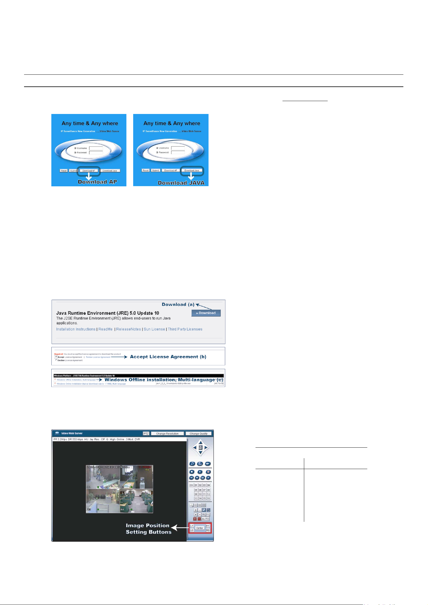
LICENSED SOFTWARE AP
7.6 Operation via IE Browser
You can view the images or operate your DVR with IE web browser. Please install the licensed software AP first.
Note: The supported PC operation systems are Windows 2000 and Windows XP.
Step 1: Key in the IP address used by your DVR in the URL address box, such as 60.121.46.236, and press Enter. You
will see the following page.
If the port number your DVR used is NOT 80, you need to key in the port number additionally. The format is IP
address:port num, for example, IP address: 60.121.46.236, port number: 888, please key in
“http://60.121.46.236:888” into the URL address box, and press “Enter”.
Step 2: Check if you already installed the latest AP version. If no, please click “Download AP” and install the latest AP.
Step 3: Check if you already installed latest Java program. If no, click “Download Java” to connect to Sun Java official
website and download the latest Java Runtime Environment (JRE) version.
a) Press “Download” to go to the download page.
b) Select “Accept License Agreement”.
c) Choose offline installation or online installation, and follow the onscreen instructions.
Step 4: Enter the user name and password, the same as the ones used at AP login. Press “Submit” when the user name
and password are correct, or “Reset” to re-enter the user name and password. You will see a similar screen as
the following when the login information is correct.
Image Position Setting:
Button Position
LT Upper Left
LD Lower Left
Center Center
RT Upper Right
RD Lower Right
All the buttons and their functions on the control panel are the same as the ones on AP control panel except for
the buttons image position setting buttons. For the information of operation, please refer to the section “7.3
Control Panel” at page 32.
-48-
Page 53
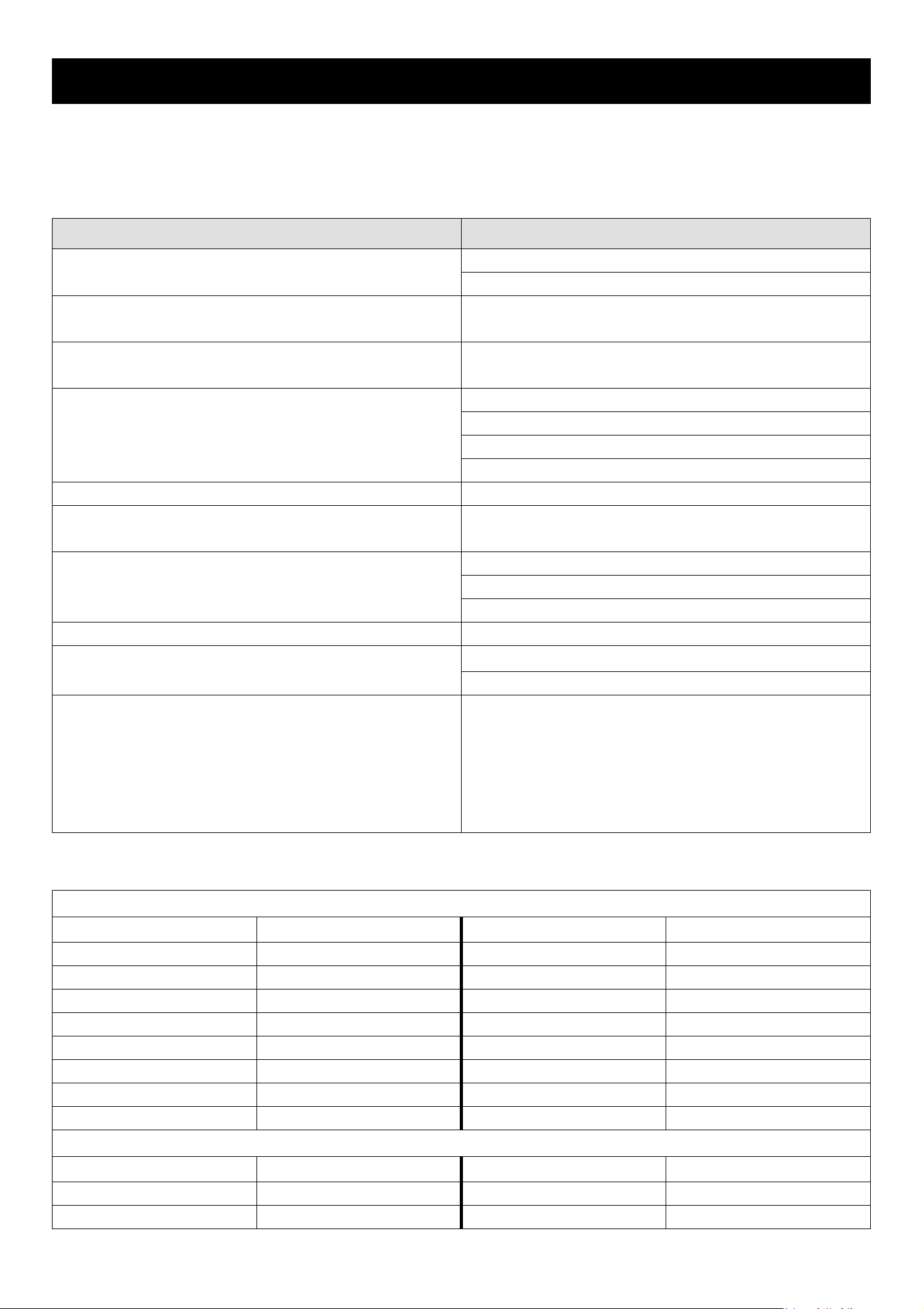
8. TROUBLESHOOTING
8.1 FAQ
Please refer to the table below for easy troubleshooting. The table describes some typical problems and also their
solutions. Please check them before calling your DVR dealer.
Problem Solution
Check power cord connection. No power
Confirm that there is power supplied from the outlet.
DVR is not working when pressing any button You might be under “Key Lock” mode. Press any key and
enter the password to exit this mode.
Timer record is not working Check if “TIMER RECORD ENABLE” option is set to
“YES”.
No live video
No recorded video Check if the HDD is installed and connected properly
DVR keeps rebooting Make sure the power connector and HDD are connected
HDD detection failed
Can’t detect your USB flash drive Replace with another USB flash drive for testing.
browser
Can’t play the recorded data on my DVR There must be at least 8192 images of recorded data for
Confirm the camera is power supplied.
Check the setting of the camera lens.
Check the monitor’s video cable and connection.
Check the camera’s video cable and connection.
closely, or change another compatible HDD.
Replace with another HDD for testing.
Replace with another HDD cable for testing.
Make sure HDD “Master”, “Slave” mode is correctly set.
Update the JAVA program. Can’t view the DVR images over the network with IE web
Update the firmware of the licensed software AP.
playback to work properly. If not, your DVR will stop the
playback.
For example, if the IPS is set to 30, the recording time
should be at least 273 seconds (8192 images / 30 IPS)
for the playback to work properly.
8.2 Default Value
◎ DVR Side
Item Default Value Item Default Value
ADMIN Password 0000 Detection OFF
GUEST Pa ssword 1111 Detec tion - L S 07
Camera - BRIG 110 Detection - SS 03
Camera - CONT 128 Detection - TS 02
Camera - SATU 128 Detection - RE 10
Camera - HUE 128 Detection - Alarm OFF
Camera - COV NO Network - IP Address 192.168.1.10
Camera - REC NO
◎ AP Side
Item Default Value Item Default Value
User Name admin Port 80
Password admin IP Address 192.168.1.10
-49-
Page 54
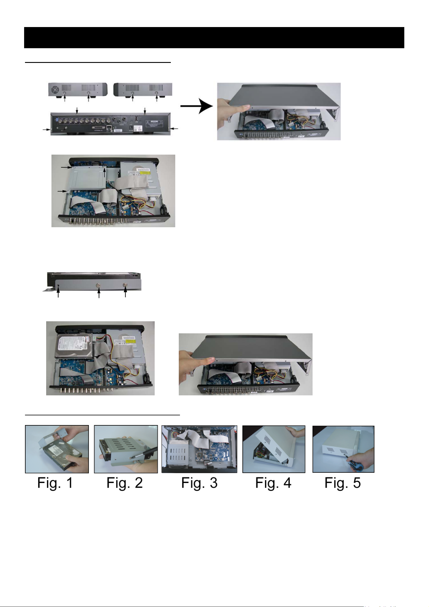
APPENDIX 1 INSTALL HDD
◎ HDD Installation for Model 1 and 5
Step 1: Loosen the screws on the upper cover and open the upper cover of the DVR
Step 2: Screw out the HDD bracket. For the positions of the HDD bracket screws, please refer to the figure below.
Step 3: Get suitable brand HDD and set the HDD mode (master / slave) according to the indication.
Step 4: Screw HDD onto the HDD bracket, two screws for each side. There are three screw holes per side on the bracket
and you can choose two of them to secure the HDD. And then screw the HDD bracket back to the DVR base.
Step 5: Connect the HDD to the power connector and IDE BUS (make sure to align the HDD precisely for pin connection).
And then close the upper cover of the DVR and fasten all the screws you loosened in the step 1.
◎ HDD Installation for Model 2, 3 and 4
Step 1: Loosen the screws on the upper cover and open the upper cover of the DVR.
Step 2: Screw out the HDD bracket.
Step 3: Get suitable brand HDD and set the HDD mode (master or single).
Step 4: Screw HDD onto the HDD bracket, two screws for each side. And then screw the HDD bracket back to the DVR
base. (Refer to Fig.1 & 2).
Step 5: Connect the HDD to the power connector and IDE BUS (make sure to align the HDD precisely for pin connection)
(Refer to Fig. 3)
Step 6: Close the upper cover of the DVR and fasten all the screws you loosened in the step 1. (Refer to Fig. 4 & 5)
-50-
Page 55
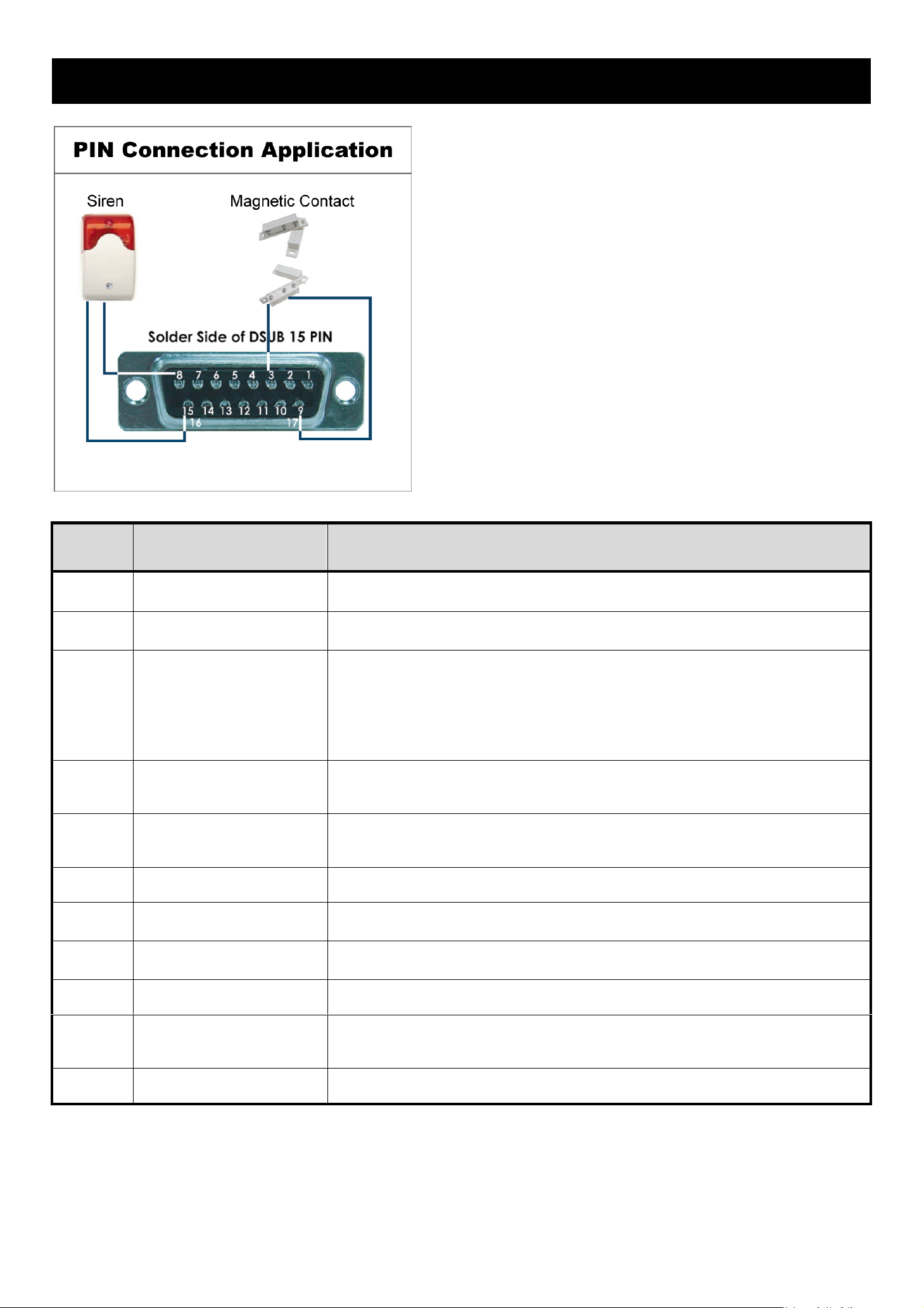
APPENDIX 2 PIN CONFIGURATION
Siren: When the DVR is triggered by alarm or
motion, the COM connects with NO and the siren
with strobe starts wailing and flashing.
Magnetic Contact: When the magnetic contact
is opened, the alarm will be triggered and the
recording is on.
PIN FUNCTION DESCRIPTION
1
2
3 ~ 6
7
8
RS232-TX
RS232-RX
ALARM INPUT
EXTERNAL ALARM NC
EXTERNAL ALARM NO.
DVR can be controlled remotely by the keyboard of PC by using RS-232 serial communication
signals. Please refer to “APPENDIX 3 RS-232 PROTOCOL” for details.
DVR can be controlled remotely by the keyboard of PC by using RS-232 serial communication
signals. Please refer to “APPENDIX 3 RS-232 PROTOCOL” for details.
To connect the wire from ALARM INPUT ( PIN 3 -- 6 ) to GND ( PIN 9 ) connector, DVR will start
recording and the buzzer will be on.
*“MENU -> ADVANCE -> DETECTION -> DETECTION SETUP -> ALARM” is set to “Low”:
When the alarm input signal is “ Low ”, the unit starts to record and buzzer.
*“MENU -> ADVANCE -> DETECTION -> DETECTION SETUP -> ALARM” is set to “High”:
When the alarm input signal is “ High ”, the unit starts to record and buzzer.
Under the normal operation, COM connects with NC and disconnects from NO. But when any
alarm is triggered, COM disconnects with NC and connects with NO.
Attention: The voltage restriction is under DC24V 1A.
Under the normal operation, COM disconnects with NO. But when any alarm is triggered, COM
connects with NO.
Attention: The voltage restriction is under DC24V 1A.
9
10
11
12 ~ 14
15
16 ~ 17
GND
RS485-B
RS485-A
PIN OFF
EXTERNAL ALARM COM
GND
Signal GND
DVR can be controlled remotely by the keyboard of PC by using RS-485 serial communication
signals.
DVR can be controlled remotely by the keyboard of PC by using RS-485 serial communication
signals.
Under the normal operation, COM disconnects with NO. But when any alarm is triggered, COM
connects with NO.
Attention: The voltage restriction is under DC24V 1A.
Earth GND
-51-
Page 56

APPENDIX 3 RS-232 PROTOCOL
Use your PC keyboard to simulate your DVR keypad.
Data: REMOTE PROTOCOL use 8 bit data, 1 start bit, 1 stop bit.
ACT C0H ID FUNCTION STOP
(FFH) (7FH)
FUNCTION CODE ASCII FUNCTION CODE ASCII
KEY_MENU
KEY_ENTER
KEY_PLUS
KEY_MINUS
KEY_UP
KEY_DOWN
KEY_LEFT
KEY_RIGHT
KEY_POWER
KEY_REC
KEY_PLAY
0x4D M
0x0D ENTER
0x6b k
0x6d m
0x55 U
0x4E N
0x4C L
0x52 R
0x57 W
0x72 r
0x50 P
KEY_DWELL
KEY_CH1
KEY_CH2
KEY_CH3
KEY_CH4
KEY_CH5
KEY_CH6
KEY_CH7
KEY_CH8
KEY_CH9
KEY_CH10
0x65 e
0x31 1
0x32 2
0x33 3
0x34 4
0x35 5
0x36 6
0x37 7
0x38 8
0x39 9
0x41 A
KEY_SLOW
KEY_ZOOM
KEY_KEY LOCK
KEY_AUDIO
KEY_SEARCH
KEY_PTZ_MODE
KEY_PTZ_PRESET
KEY_PTZ_ZOOM_IN
KEY_PTZ_ZOOM_OUT
KEY_MODE
KEY_4 CUT
0x53 S
0x5A z
0x4B K
0x64 d
0x73 S
0x70 p
0x71 q
0x69 i
0x66 f
0x6f o
0x61 a
KEY_CH11
KEY_CH12
KEY_CH13
KEY_CH14
KEY_CH15
KEY_CH16
KEY_EJECT_DVD
KEY_IRIS_NEAR
KEY_IRIS_FAR
KEY_PTZ_LIGHT
KEY_PTZ_WIPER
0x42 B
0x43 C
0x44 D
0x45 E
0x46 F
0x47 G
0x6a j
0x67 g
0x68 h
0x6c l
0x77 w
KEY_9 CUT
KEY_16 CUT
KEY_SET_CHANNEL
0x62 b
0x63 c
0x6e n
-52-
Page 57

APPENDIX 4 RECORDING TIME TABLE
The recording time varies depending on the following factors:
‧ Different camera quality
‧ Different picture composition (such as frequency of the object movement)
Recording Time For Model 1, 2 and 5
RECORD TIME
RECORD MODE QUALITY IPS
FOR 500GB
(HOUR)
RECORD DAY
FRAME
30 436.9 18.2
15 767.6 32
BEST
7 1398 58.2
3 2258.6 94.1
30 552.8 23
15 971.3 40.5
HIGH
7 1768.9 73.7
3 2857.9 119.1
30 726.2 30.3
15 1276 53.2
NORMAL
7 2323.9 96.8
3 3754.5 156.4
30 1173.7 48.9
15 2062.2 85.9
BASIC
7 3755.9 156.5
CIF
3 6068.1 252.8
120 520.8 21.7
60 915.1 38.1
BEST
30 1666.7 69.4
15 2692.7 112.2
120 734.2 30.6
60 1290 53.8
HIGH
30 2349.5 97.9
15 3795.9 158.2
120 966.2 40.3
60 1697.6 70.7
NORMAL
30 3091.8 128.8
15 4995.2 208.1
120 1338.7 55.8
BASIC
60 2352.1 98
30 4283.8 178.5
15 6921 288.4
-53-
Page 58

Recording Time For Model 3 and 4
RECORD TIME
RECORD MODE QUALITY IPS
FRAME
BEST
HIGH
NORMAL
30 127.78 5.3
15 236.11 9.8
7 511.11 21.3
3 980.65 40.9
30 159.72 6.7
15 305.55 12.7
7 633.89 26.4
3 1209.72 50.4
30 179.17 7.5
15 352.78 14.7
7 626.11 28.6
3 1263.88 52.7
FOR 500GB
(HOUR)
RECORD DAY
CIF
30 222.22 9.3
15 405.56 16.9
BASIC
7 927.78 38.7
3 1637.5 68.2
120 763.89 31.8
60 1416.67 59
BEST
30 2156.94 89.9
15 4134.72 172.3
120 965.28 40.2
60 1655.55 69
HIGH
30 3398.61 141.6
15 4833.31 201.4
120 1120.83 46.7
60 2166.38 90.3
NORMAL
30 4105.56 171.1
BASIC
15 5154.17 214.8
120 1563.89 65.2
60 2494.44 103.9
30 4472.22 186.3
15 6681.94 278.4
-54-
Page 59

APPENDIX 5 COMPATIBLE USB FLASH DRIVE BRAND
Please upgrade the firmware of the DVR to the latest version to ensure the accuracy of the following table. If the USB
flash drive is not supported by the DVR, the "USB ERROR" message will be shown on the screen.
Note: Please use your PC to format the USB flash drive as "FAT 32".
Compatible USB Flash Drives
MANUFACTURER MODEL CAPACITY
256MB
Transcend JetFlash 110
512MB
Kingston DataTraveler DTI KUSBDTI/256FE
PQI Cool Drive (U339)
APACER HANDY STENO HF202
SANDISK Cruzer Micro
256MB
512MB
256MB
512MB
256MB
512MB
128MB
256MB
512MB
-55-
Page 60

APPENDIX 6 COMPATIBLE HDD BRAND
Please upgrade the firmware of the DVR to the latest version to ensure the accuracy of the following table.
Compatible HDD BRAND
MANUFACTURER MODEL CAPACITY ROTATION
Deskstar 7K250, HDS722516VLAT20 160GB 7200 rpm
HDS722516VLAT80 160GB 7200 rpm
HITACHI
Maxtor
HDS722516DLAT80 160GB 7200 rpm
Deskstar 7K250, HDS722525VLAT80 250GB 7200 rpm
Deskstar 511DHT0021 500GB 7200 rpm
DiamondMax Plus 9, Model#6Y160L0 160GB 7200 rpm
DiamondMax 10 6L160R0 160GB 7200 rpm
DiamondMax 10 6L200R0 200GB 7200 rpm
DiamondMax 10 6L200PO 200GB 7200 rpm
MaxLine Plus , Model#7Y250P0Ⅱ 250GB 7200 rpm
DiamondMax 10 6L250R0-3 250GB 7200 rpm
DiamondMax 10 HDMA6L300RO-3 300GB 7200 rpm
Barracuda 7200.7 Plus, ST3160023A 160GB 7200 rpm
Barracuda 7200.8 ST3200826A 200GB 7200 rpm
Barracuda 7200.8 ST3250826A 250GB 7200 rpm
Barracuda 7200.8 ST3300831A/P 300GB 7200 rpm
Seagate
Barracuda 7200.8 ST3400832A/P 400GB 7200 rpm
7200.9 ST3200827A/P 200GB 7200 rpm
7200.10 ST3250620A/P 250GB 7200 rpm
7200.10 ST3320620A/P 320GB 7200 rpm
Caviar SE WD1600JB 160GB 7200 rpm
Caviar WD2000BB-00DWA0 200GB 7200 rpm
Western Digital
Caviar SE WD2500JB 250GB 7200 rpm
Cavir RE WD2500SB-01KBC0 250GB 7200 rpm
-56-
 Loading...