

Page 1
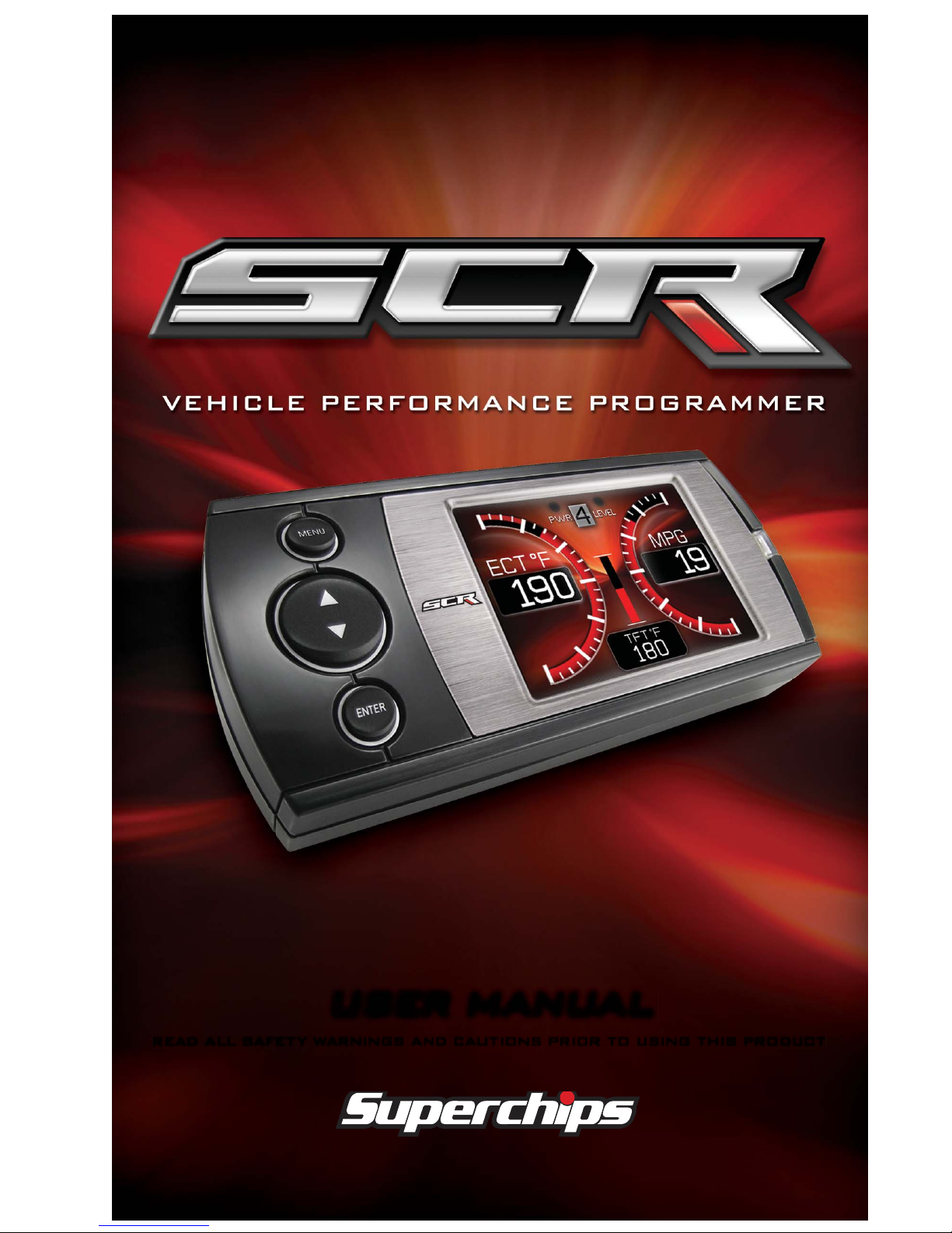
user manual
read all safety warnings and cautions prior to using this product
Page 2

TABLE OF CONTENTS
2
TABLE OF CONTENTS
SAFETY ....................................................................4
SAFETY WARNING & CAUTION ..................................................... 4
SAFETY GUIDELINES .................................................................... 5
LIMITED 1 YEAR WARRANTY ........................................................ 6
WARRANTY ..............................................................6
VEHICLE WARRANTIES ................................................................. 6
READ ME ..................................................................8
PRODUCT REGISTRATION ............................................................ 8
PARTS INCLUDED ......................................................................... 9
IN THE BOX ..............................................................9
OPERATING INSTRUCTIONS ................................ 10
SCREEN LAYOUTS & FUNCTIONALITY ...................................... 10
GETTING STARTED ....................................................................... 11
VEHICLE PARAMETER ID’s (PIDs) ................................................11
NAVIGATING THE MAIN MENU ................................................... 12
SHOW ALERTS ......................................................................... 12
SHOW MAINTENANCE DUE......................................................... 13
DIAGNOSTICS .......................................................................... 13
--TROUBLE CODES-- ............................................................... 13
--PERFORMANCE TESTS-- ....................................................... 13
--RECORDS-- ......................................................................... 14
--MILEAGE COACH-- ............................................................... 14
--DATA LOGGING-- ................................................................. 17
MAINTENANCE MANAGER .......................................................... 17
--ODOMETER SETUP-- ............................................................. 18
--MAINTENANCE SETUP-- ........................................................ 18
--ALERT THRESHOLD-- ........................................................... 19
OPTIONS MENU ....................................................................... 19
--ALERT OPTIONS (SETTINGS)-- ............................................... 19
--SOUND DURATION-- ............................................................ 20
--SCREEN LAYOUT-- .............................................................. 20
--BACKLIGHT AUTODIM-- ......................................................... 21
--MENU TIME-OUT-- ................................................................ 21
--ACCESSORY OPTIONS-- ....................................................... 21
--UNITS-- ............................................................................. 22
--FACTORY RESET-- ............................................................... 22
HELP MENU ............................................................................ 22
--PRODUCT INFO-- ................................................................ 22
--VEHICLE INFO-- .................................................................. 23
--CONTACT INFO-- ................................................................. 23
--TECHNICAL SUPPORT TOOLS-- ............................................. 23
Page 3

TABLE OF CONTENTS
3
PROGRAMMING THE VEHICLE ...................................................24
--PROGRAMMING LEVELS-- .....................................................24
CUSTOMIZATION ......................................................................... 26
FUSION SOFTWARE UPDATES ................................................... 27
INTERNET UPDATES ............................................ 27
USING FUSION SOFTWARE ........................................................27
PROGRAMMING ERRORS ...........................................................28
--UPDATE REQUIRED-- ............................................................28
--NON-STOCK CONDITION-- .....................................................29
APPENDIX ............................................................. 29
TIPS ............................................................................................. 30
TROUBLE-SHOOTING ................................................................. 31
COMMONLY USED ACRONYMS .................................................. 32
INDEX ................................................................... 33
Page 4
SAFETY
4
S A F E T Y
SAFETY
W A R N I N G &
WARNING &
C A U T I O N
CAUTION
Throughout this User Guide (hereafter noted as User Manual or
Manual) you will see important messages regarding your safety or
the protection of your vehicle. These messages are designated by
the words WARNING or CAUTION.
WARNING indicates a condition that may cause serious
injury or death to you, your passengers or others nearby. Pay
careful attention to these Warning messages, and always comply with them. They could save a life.
CAUTION indicates a condition that could cause damage to
your vehicle. It is important to install and operate your Superchips product in conformance with instructions in this Manual.
Cautions alert you to particularly important things that will keep
your vehicle operating properly.
This Superchips Product is a high-performance product. As such,
it does present some risks of which you should be fully aware. Do
not use this product until you have carefully read the following safety
information and the Owner Agreement.
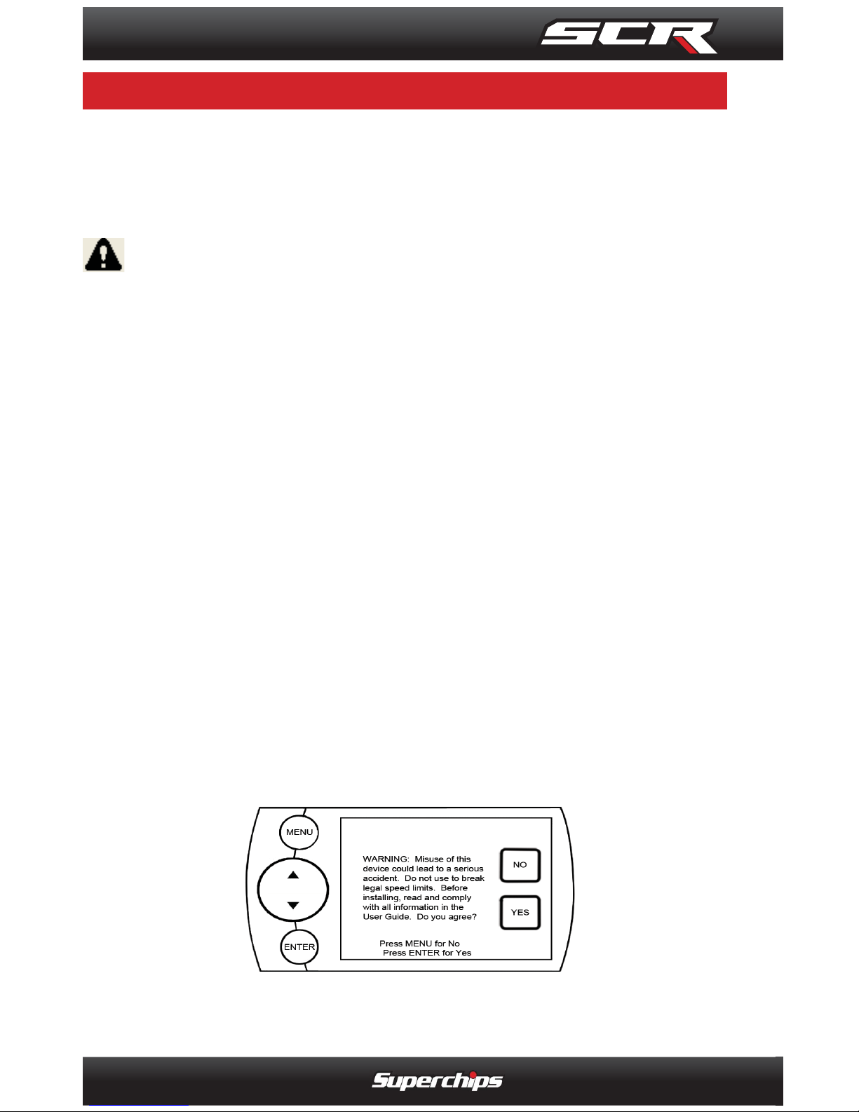
NOTE: After the device has been installed, the screen and logo
will appear followed by a warning and compliance directive. To
indicate you accept and acknowledge the warning and compliance, press the [ENTER] or [YES] button.
Page 5
SAFETY
5
S A F E T Y G U I D E L I N E S
SAFETY GUIDELINES
1. Do not exceed legal speed limits on public roadways. Use any
enhanced speed capabilities of this product only in closed circuit,
legally sanctioned racing environments expressly for this purpose.
Loss of control from speeding on a public road could seriously injure
you, your passengers, or others on the roadway.
2. Do not operate the device while driving. Perform all adjustments
or changes while stopped. Changing a setting while driving can interfere with your attention to roadway conditions.
3. “ Stacking” performance-enhancing devices or other improper installation can cause power train failure on the road. Other products
may have features incompatible with your device. Follow all installation and operating instructions, and do not stack products.
4. Some modifi cations may affect other parts of your vehicle. For ex-
ample, if you remove/adjust the speed limiter in your vehicle, be sure
your tires and other components are rated for the increased speeds
they will have to withstand. Not doing so can lead to loss of vehicle
control. Modify the speed limiter only for use in closed circuit, legally
sanctioned racing environments, not for use on public roadways.
WARNING
Misapplication or misuse of this product could lead to a serious or fatal accident. Comply with all safety information in
this manual, and your vehicle owner’s manual. Follow safety,
installation and operating instructions in this User Manual to
assure proper use.
Page 6
WARRANTY
6
L I M I T E D 1 Y E A R
LIMITED 1 YEAR
W A R R A N T Y
WARRANTY
LIMITED 1 YEAR WARRANTY
• Superchips, (hereafter “SELLER”) gives Limited Warranty as to description, quality,
merchantability, fi tness for any product’s purpose, productiveness, or any other matter
of SELLER’s product sold herewith. The SELLER shall be in no way responsible for the
product’s open use and service and the BUYER hereby waives all rights other than those
expressly written herein. This Warranty shall not be extended or varied except by a written
instrument signed by SELLER and BUYER.
• The Warranty is Limited to one (1) year from the date of sale and limited solely to the
parts contained within the product’s kit. All products that are in question of Warranty must
be returned shipping prepaid to the SELLER and must be accompanied by a dated proof
of purchase receipt. All Warranty claims are subject to approval by Superchips.
• Under no circumstances shall the SELLER be liable for any labor charged or travel time
incurred in diagnosis for defects, removal, or reinstallation of this product, or any other
contingent expenses.
• If the BUYER sends back a failed unit that is out of warranty and chooses to buy a
refurbished unit, the refurbished unit will only carry a 90 day warranty. If the BUYER
purchases a new unit at a predetermined discounted rate, it will have the standard 1 year
warranty.
• Under no circumstances will the SELLER be liable for any damage or expenses insured
by reason of the use or sale of any such equipment.
• THE INSTALLATION OF THIS PRODUCT INDICATES THAT THE BUYER HAS READ
AND UNDERSTANDS THIS AGREEMENT AND ACCEPTS ITS TERMS AND CONDITIONS.
• IN THE EVENT THAT THE BUYER DOES NOT AGREE WITH THIS AGREEMENT,
THE BUYER MAY PROMPTLY RETURN THIS PRODUCT, IN A NEW AND UNUSED
CONDITION, WITH A DATED PROOF OF PURCHASE, TO THE PLACE OF PURCHASE
WITHIN THIRTY (30) DAYS FROM DATE OF PURCHASE FOR A FULL REFUND.
• NOTE: This warranty is void for any new products purchased through auction
web sites. Warranty is valid only for new products purchased through Authorized
Dealers (proof of purchase required for all warranty claims).
IMPORTANT INFORMATION
• Many of our customers ask, “Will your product void my vehicle’s manufacturer’s warranty?” While the answer is straightforward from a legal standpoint, it’s important to educate
our customers (and all aftermarket consumers) on some industry realities and offer some
common sense precautions to minimize your risk. Superchips is committed to providing quality products that are safe to use. Our products do not cause damage to a vehicle
when used as intended.
• Consumers of aftermarket products are protected by the Federal Magnusson-Moss
Warranty Act. The Act states that if something breaks on your vehicle and you take it in for
warranty repair, the dealer must honor your warranty unless whatever modifi cations you
have added to your vehicle actually caused the problem in question.
• However, the reality is that many dealerships have been known to void warranties on
vehicles that use aftermarket products as a matter of policy. This applies in particular to
those aftermarket products that produce horsepower, such as performance enhancement
“chips,” modifi ed intake manifolds, or aftermarket exhaust systems, regardless of product
brand.
• You have strong legal protection as a consumer in regard to your vehicle’s warranty.
V E H I C L E W A R R A N T I E S
VEHICLE WARRANTIES
Page 7
WARRANTY
7
However, Superchips strongly recommends you always disconnect and remove your
module/programmer and monitor when you take your vehicle to a dealer for warranty
work. In addition, leaving the product connected may affect dealer diagnostic analysis and
scan tool functions. Superchips makes every effort to produce product that can be easily
removed.
• NOTE: Even if you disconnect your device, your dealer can detect the use of any
programmer—even if the device has been removed.
SERVICE CENTER AND COMPATIBILITY CAUTIONS
• CAUTION: RETURN YOUR VEHICLE TO STOCK BEFORE TAKING IT TO A SERVICE CENTER. All Superchips modules and programmers are built to operate with OEM
calibrations. If you take your vehicle to a service center they may, by your request or
otherwise, update your vehicle’s calibrations. If this happens and your vehicle has not
been returned to stock your device will no longer be capable of programming your vehicle.
Superchips updates its active products (i.e. those currently being manufactured) to work
effectively with updated OEM calibrations. However, this process can take some time as
Superchips is not always made aware of calibration changes made by the OEM. In the
case of discontinued products, Superchips cannot ensure that your unit will work effectively if you take your vehicle to a dealership and you are given, by your request or otherwise,
a new calibration.
• CAUTION: If you have used another tuner/programmer on your vehicle, you will
need to program the vehicle back to stock and remove the device before using this
product. Failure to return to stock may result in PCM failure or engine damage. Programming your vehicle may expose existing defects in the vehicle’s PCM that could
disable your vehicle. It is advised that you do not program your vehicle in remote
locations in case of vehicle failure.
• CAUTION: The SCR programmer was developed on stock vehicles with no aftermarket bolt-on parts; as such, the performance changes implemented by the SCR
may not be compatible with certain aftermarket power add-ons. See below for a
brief explanation of how the SCR tuning may be affected by certain aftermarket
devices.
COLD AIR INTAKE (CAI) KITS
There are currently a large number of CAI kits on the market. These kits are designed to
improve air fl ow and temperature. Some of these kits may be compatible with the SCR
programmer; however others may cause a lean condition when used in conjunction with
the SCR tuning.
MECHANICAL MODIFICATIONS
Mechanical modifi cations such as headers, upgraded camshafts, displacement changes,
cylinder head improvements etc. will change the airfl ow characteristics of an internal com-
bustion engine. This may cause the tuning to be incompatible with the SCR tuning.
FORCED INDUCTION (TURBOCHARGERS OR SUPERCHARGERS)
Turbochargers and Superchargers drastically change the dynamics/performance of the
engine, and its fueling/timing needs. Additional hard parts and custom tuning are required
to run a forced induction system on an engine that was originally designed as a Naturally
Aspirated (NA) engine.
Page 8
READ ME
8
P R O D U C T
PRODUCT
R E G I S T R A T I O N
REGISTRATION
C A R B / E P A C O M P L I A N C E
CARB/EPA COMPLIANCE
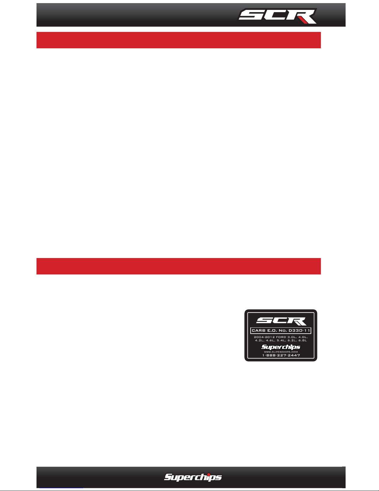
This product meets the emissions compliance requirements of the California Air Resources Board and Federal
Environmental Protection Agency and is legal for sale and
use on pollution-controlled vehicles operated on public
streets and highways. It must be installed and operated according to the instructions provided in this user’s
manual. Included with this product is a sticker like the one
pictured for you to keep in your vehicle. You can either apply it somewhere on
the vehicle (e.g., the inside end of driver’s door) or simply store it in your glove
box. The purpose of these stickers is to inform anyone who may have questions
regarding the use of your Superchips product and how it affects emissions. For
example, it would be something to show an emissions technician if questioned
when taking your vehicle in for an emissions check to let him/her know the product is CARB emissions compliant.
NOTE: The stickers included in some products apply to products that have
received CARB certifi cation for emissions compliance.
BENEFITS OF PRODUCT REGISTRATION
-Your Safety - Registering your product allows us to know exactly which
product you have and provide important product updates to you that improve the quality and/or safety of the product.
-Enhanced Features - All Superchips products are easily updated via the
internet. We are constantly adding new features and improvements to
our product that we know you will want to enjoy.
-Confi rmation of Ownership - Provides a record in case of product loss,
theft, or required warranty work. When you call us for support our team
will already have much of the information they need to help you.
-Improved Product Development - Helps us better understand you (our
customers) and design products that meet your needs.
-Special Offers - Allows us to inform you about special offers on accessories and/or new products that fi t your vehicle and enhance your driving
experience.
Page 9
IN THE BOX
9
P A R T S I N C L U D E D
PARTS INCLUDED
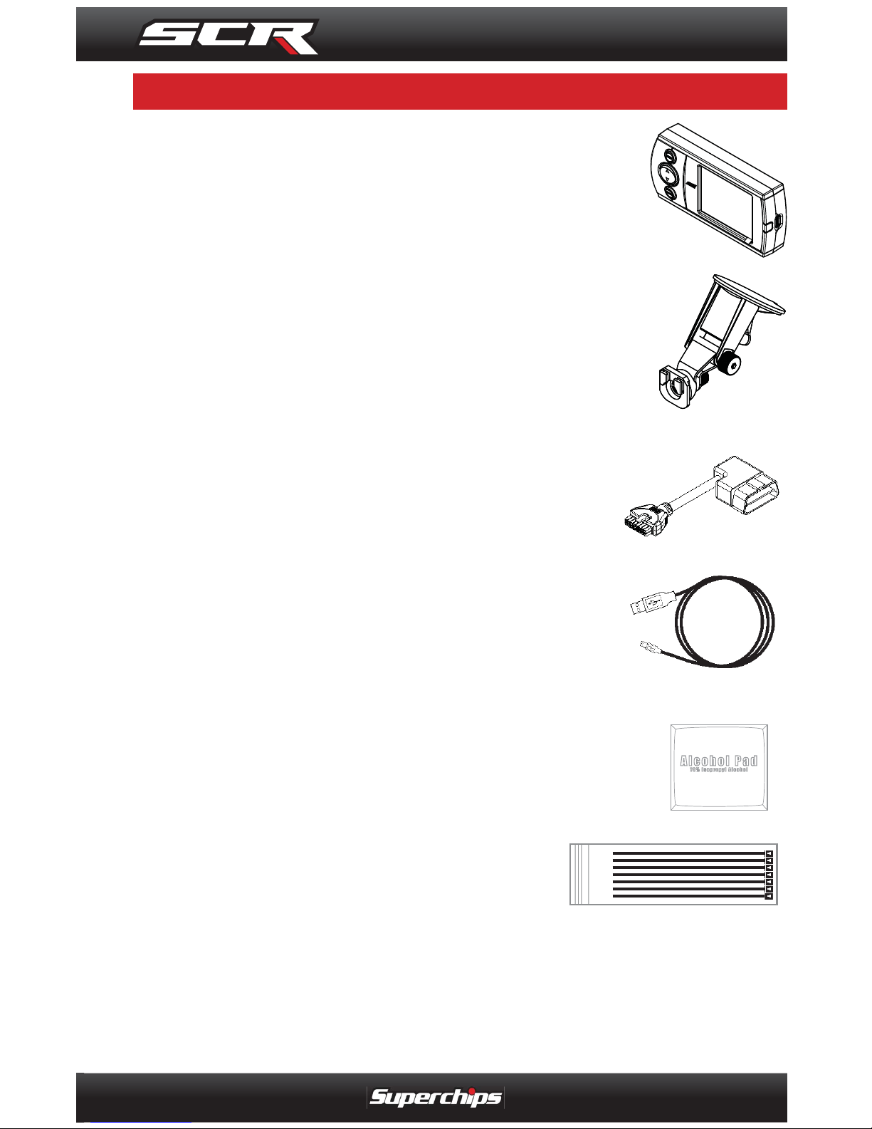
SCR DEVICE
The SCR device provides you with an interface to
change the performance programming of your vehicle
and display multiple vehicle parameters in real time.
WINDSHIELD MOUNT
The mount supplied with your kit is designed to give
you fl exibility in mounting your device anywhere on
your windshield. It is equipped with a locking suction
cup, a vertically adjustable arm, and a 180 pivot head
which allows you to fi ne tune the viewing angle.
OBDII CABLE
The purpose of this cable is to provide a communication link between your vehicle and your device
as well as power.
MINI USB CABLE
The USB cable is used to connect your device to
your PC in order to perform fi rmware and calibra-
tion updates using the Fusion software.
ALCOHOL PAD
The alcohol pad is supplied for cleaning the windshield
prior to mounting the suction cup mount.
ZIP-TIES
Use these zip-ties to fasten the OBDII cable
under the dash, and away from moving parts
such as foot pedals.
Page 10
OPERATING INSTRUCTIONS
10
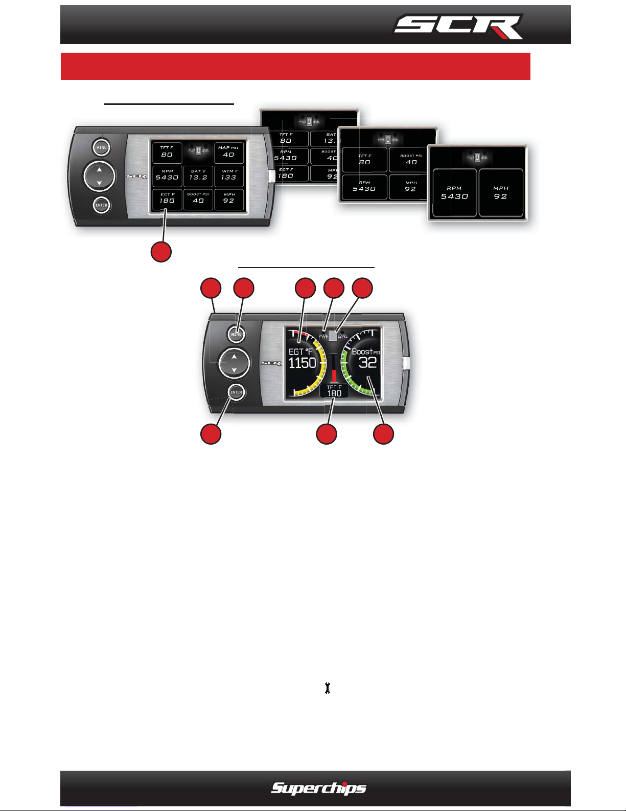
8 Gauge Layout
6 Gauge
4 Gauge
2 Gauge
3
1. The Up/Down Arrow Buttons are used to select the menu items and in-
crease or decrease values.
2. The Menu Button gives you access to the main menu or can be used to exit
out of a menu screen.
3. The Enter Button, if pressed, directs you to the PID Menu where you are
able to modify what each gauge displays.
4. Analog Gauges display vehicle Parameter IDs (PIDs)
5. Digital Gauges display vehicle Parameter IDs (PIDs)
6. The Alert Indicator light will illuminate (red) when an alert limit is exceeded.
If the light is blue and contains a wrench
your Maintenance Manager is
letting you know a maintenance item is ready to be serviced.
7. The Power Level Indicator represents the current power level. 0 repre-
sents stock.
ANALOG GAUGES
42
3
1
5
6
7
45
DIGITAL GAUGES
S C R E E N L A Y O U T S & F U N C T I O N A L I T Y
SCREEN LAYOUTS & FUNCTIONALITY
Page 11
OPERATING INSTRUCTIONS
11
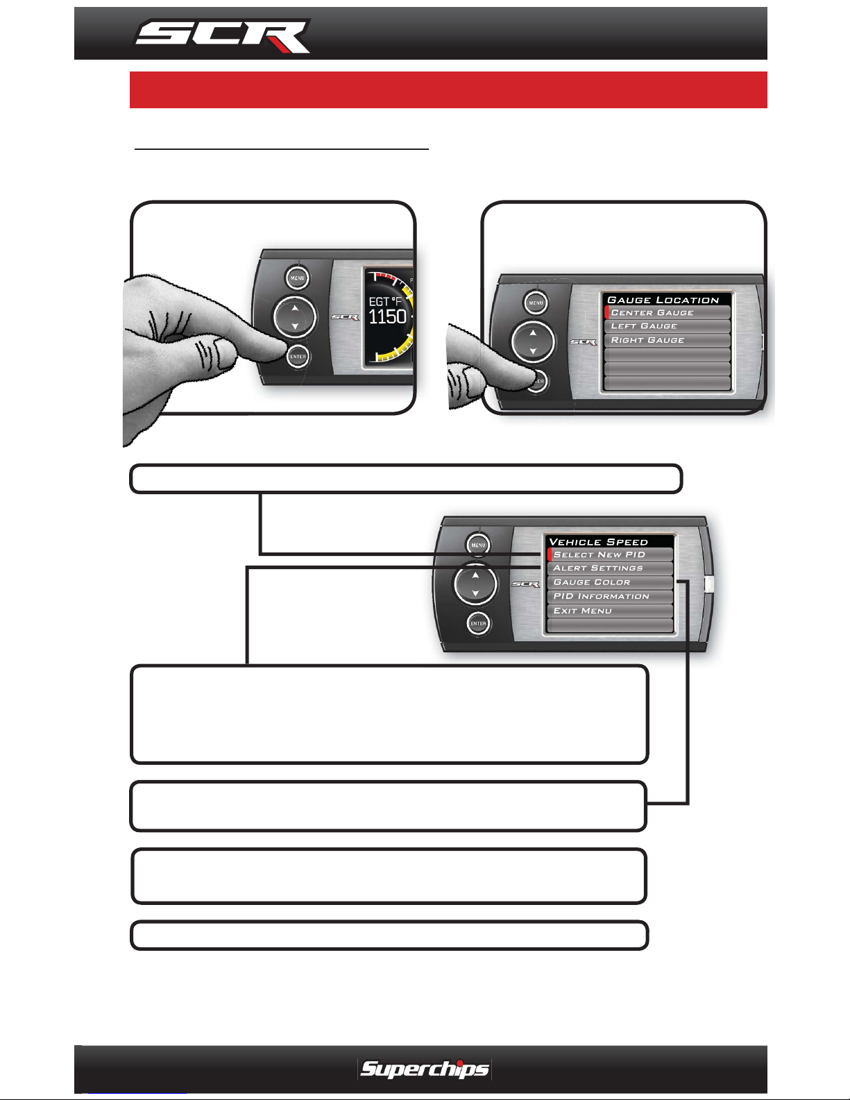
STEP 1 - PRESS ENTER
VEHICLE PARAME TER ID’s ( PIDs)
STEP 2 - CHOOSE THE
GAUGE TO MODIFY, THEN
PRESS ENTER
STEP 3 - SELECT A NEW PID FROM THE PROVIDED LIST
STEP 4 - SET THE ALERT VALUES ACCORDINGLY.
(FOR MORE INFORMATION ON ALERT SETTINGS,
PLEASE REFER TO THE ALERT OPTIONS (SETTINGS)
SECTION
STEP 5 - CHOOSE A GAUGE COLOR. (COLORS CAN
ONLY BE MODIFIED ON ANALOG STYLE GAUGES)
STEP 6 - VIEW PID INFORMATION TO UNDERSTAND
WHAT THE PID IS AND/OR WHAT IT MONITORS
STEP 7 - WHEN YOU ARE FINISHED, EXIT THE MENU
To change what PID each gauge displays, follow these steps:
G E T T I N G S T A R T E D
GETTING STARTED
Page 12
OPERATING INSTRUCTIONS
12
NOTE: The following will only show
under certain circumstances:
1. “Show Alerts” will only show if an
alert is active.
2. “Show Maintenance Due” will
only show if your Maintenance Manager is turned on and a maintenance
item is due.
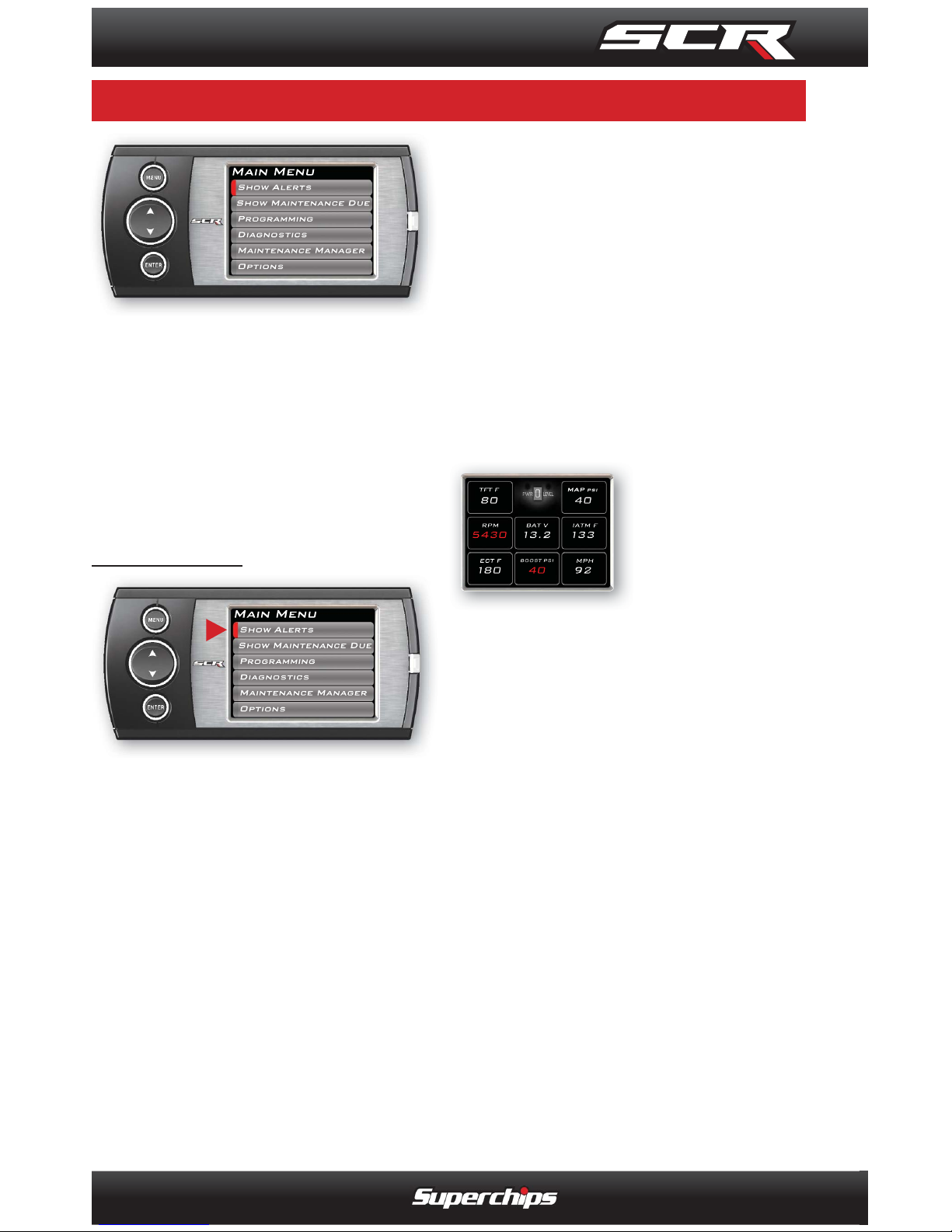
SHOW ALERTS
If this option is displayed in the
MAIN MENU, the SCR device
is alerting you that one or more
of the PARAMETER IDs (PIDs)
being displayed is outside the
values you specifi ed. There are
two methods in which the alerts
are viewed:
MAIN SCREEN METHOD
While viewing the gauges, two
things will automatically occur:
1. The alert notifi cation will
sound (only if the sound is
turned on for that specifi c PID).
The sound will turn off after a
few seconds depending on the
sound duration you have set.
2. The gauge value will fl ash
red. It will continue fl ashing as
long as the parameter is outside
the user-defi ned value.
ALERTS SCREEN METHOD
The Alerts
screen will show
all parameters
for which an
alert has been
set. If an alert value is outside
the user-defi ned setting, it will
fl ash red. The Alerts screen will
stay in view for a minimum of
three seconds, until no alert condition exists, or until the MENU
button is pressed, at which point
it will return to the main gauge
screen.
If you have exited the Alerts
Screen you can return to the
screen by entering the Main
Menu and selecting Show
Alert s.
NOTE: For more information
on how to set the Alerts, Refer
to the: ALERT SETTINGS section of this manual.
N A V I G A T I N G T H E M A I N M E N U
NAVIGATING THE MAIN MENU
Page 13
OPERATING INSTRUCTIONS
13
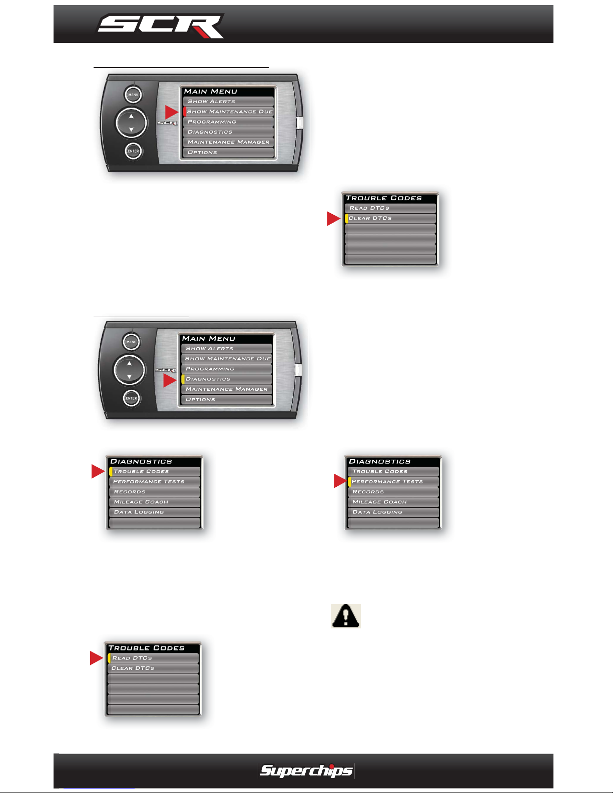
SHOW MAINTENANCE DUE
This feature allows you to quickly view which Maintenance Item
is up for service. Refer to the
Maintenance Manager section
of this manual for more information.
--TROUBLE CODES--
When your
PCM detects
a problem with
your vehicle it
sets a trouble
code. Use this menu item to
retrieve the code, and to clear it
after retrieval.
--- READ DTCs---
If you want to
read the DTCs
on your vehicle
follow these
instructions:
1. Make sure the Key is in the
ON position.
2. Select the Trouble Codes
from the Diagnostics menu.
3. Select Read DTCs from the
menu.
---CLEAR DTCs---
After you have
retrieved the
trouble codes
and written
them down,
you can clear the trouble codes
by selecting Clear DTCs from
the menu. This will erase any
of the codes currently set. If
the codes come back we recommend you see a qualifi ed
mechanic who can accurately
diagnose/repair the problem.
--PERFORMANCE TESTS--
Performance
tests can be
helpful for
measuring
performance
gains after vehicle modifi cations
( e.g. intake, exhaust, programers, etc).
WARNING: Do not use the
Performance Tests feature to
break any traffi c laws.
The CSR device allows you to
test the performance of your
vehicle by timing 0-60 and
DIAGNOSTICS
Page 14
OPERATING INSTRUCTIONS
14
quarter mile runs (instructions
are provided in the Instructions
menu). The results recorded by
the Performance Test features
will likely differ from what you’ll
see on a drag-strip or other
racing venues. Incorrect speedometer calibration, data sample
rate, and tire slippage can cause
miscalculations in the displayed
results.
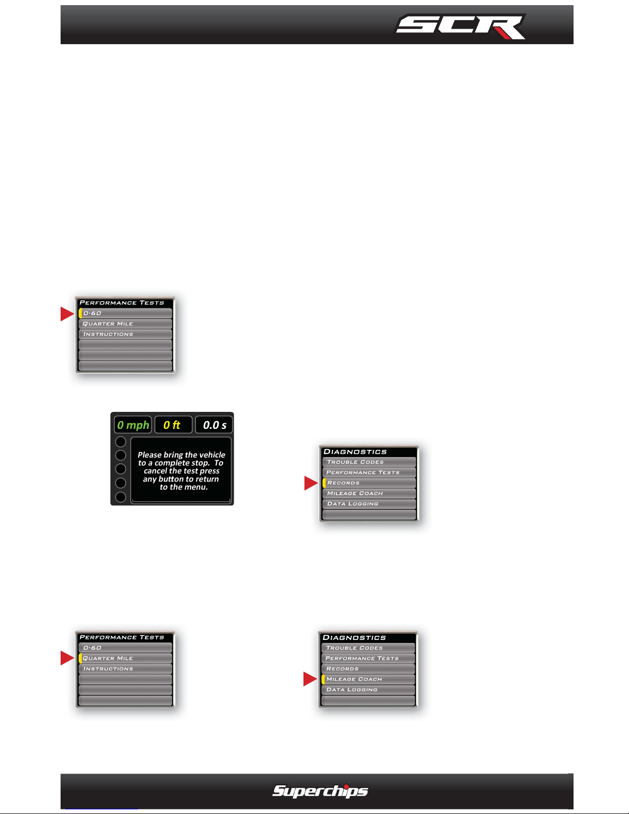
---0 to 60 MPH TEST---
After selecting
the 0-60 menu
option, the following screen
will appear:
After bringing the vehicle to a
stop, follow the directions noted
on the screen.
---QUARTER MILE TEST---
Select the
Quarter Mile
menu item
and Figure 10
will appear.
After bringing the vehicle to a
stop, follow the directions noted
on the screen. The Quarter mile
test will prompt you with a drag
strip style light tree. If you watch
the circles on the left they will
light up yellow, then green. If
you go before green appears
then a red light will light up in the
bottom showing that you started
too early. If you don’t start early
then you will see a green light
remain in the bottom circle.
When you’ve fi nished the quar-
ter mile run the device will
display the ending mph, the
distance traveled in ft., and the
elapsed time it took to reach 1/4
mile. In addition it will graph
your Distance vs Speed so you
can better analyze the run.
-- RECORDS--
Records contain certain
parameters for
later review.
This is useful on the drag strip, or when
you are trying to trouble shoot a
problem.
-- MILEAGE COACH--
The Mileage
Coach feature provides
useful tips and
tools that help
you learn ways to improve your
fuel mileage.
Page 15
OPERATING INSTRUCTIONS
15
There are 3 PID options that
directly relate to the Mileage
Coach feature. They are:
Mileage Average
This PID displays the calculated
average MPG or L/100km and
is updated continuously while
driving.
NOTE: The average is calculated only when the PID is
being displayed on the Main
Gauge Screen.
This value will typically change
more during start/stop driving,
and less on the highway.
Mileage Instantaneous This
PID shows a conscientious driver how to vary the pressure on
the gas pedal to save fuel every
second. The value is displayed
in either MPG or L/100km.
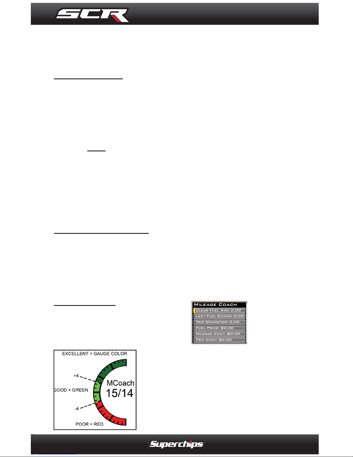
Mileage Coach
This PID takes the Average and
Instantaneous values mentioned
above and creates a visual tool
to help maximize your fuel econ-
omy. This
PID is best
viewed using one of
the Analog
Gauge
locations.
The level
indicator has been separated
into 3 colors. The Green color
in the middle indicates that your
driving habits are producing
good fuel economy. The Red
indicates that your driving habits
are not producing the best fuel
economy and that there is room
to improve. The upper “Gauge
Color” (depends on the color
you chose in the PID properties)
indicates that your driving habits
have been maximized, and you
are getting the most out of your
fuel.
NOTE: For instruction on how
to display the Mileage Coach
IDs, refer to the Getting Started section of this manual.
MILEAGE COACH SETUP
1. Enter the MAIN MENU, select DIAGNOSTICS, then select
MILEAGE COACH. The following screen will be displayed:
2. Become familiar with each
option within the Mileage Coach
feature set and adjust values
accordingly. Refer to the follow
explanations for each of the options available.
Page 16
OPERATING INSTRUCTIONS
16
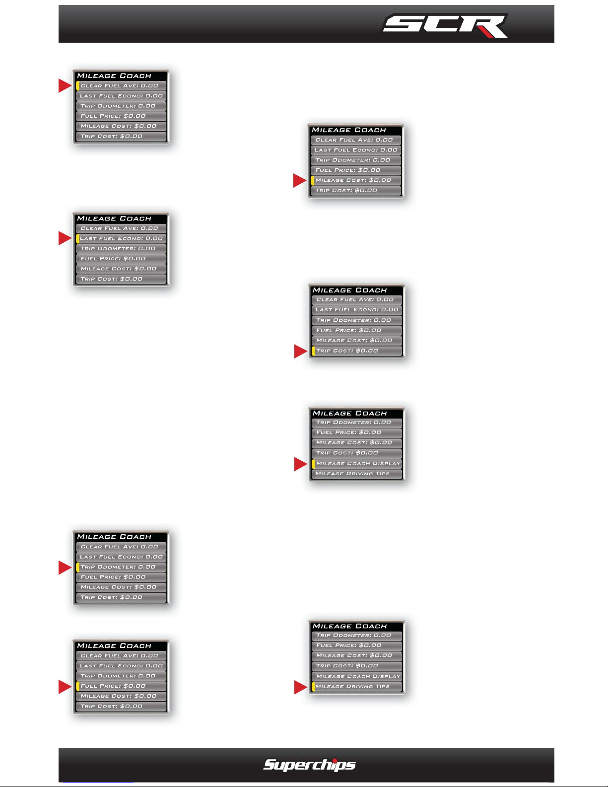
---CLEAR FUEL AVERAGE---
Use this option to clear
the calculated
average displayed in the
Mileage Average PID.
---LAST FUEL ECONOMY---
This option
allows you
to enter your
actual Fuel
Economy
Value. This value is important
and should be calculated and
entered regularly. This can be
manually calculated by dividing
the distance travelled by how
much fuel you have used (Distance/Fuel = Fuel Economy).
Some vehicles have their own
Fuel Economy average that is
displayed in cab and may be
used instead of a manual calculation.
---TRIP ODOMETER---
This value is
used to calcu-
late the Trip
Cost and Fuel
Average.
---FUEL PRICE---
In order to
calculate your
Mileage and
Trip Costs, the
price of fuel
purchased must fi rst be entered.
For example: Fuel purchased at
$3.58/Gal should be entered as
3.58.
---MILEAGE COST---
This value is
a calculated
average based
on how many
miles you have
traveled and the Fuel Price you
entered.
---TRIP COST---
This value
is calculated
from the Fuel
Price and the
Trip Odometer.
---MILEAGE COACH DISPLAY---
There are two
ways to display the Mileage Coach
PID.
1. Show Difference: Difference
between Instantaneous and
Average.
2. Show Values: Displays as
Instantaneous | Average.
---MILEAGE DRIVING TIPS---
These tips
are intended
to give you
general infor-
mation regarding driving habits or anything
that will help maximize your fuel
Page 17
OPERATING INSTRUCTIONS
17
economy and overall driving
experience.
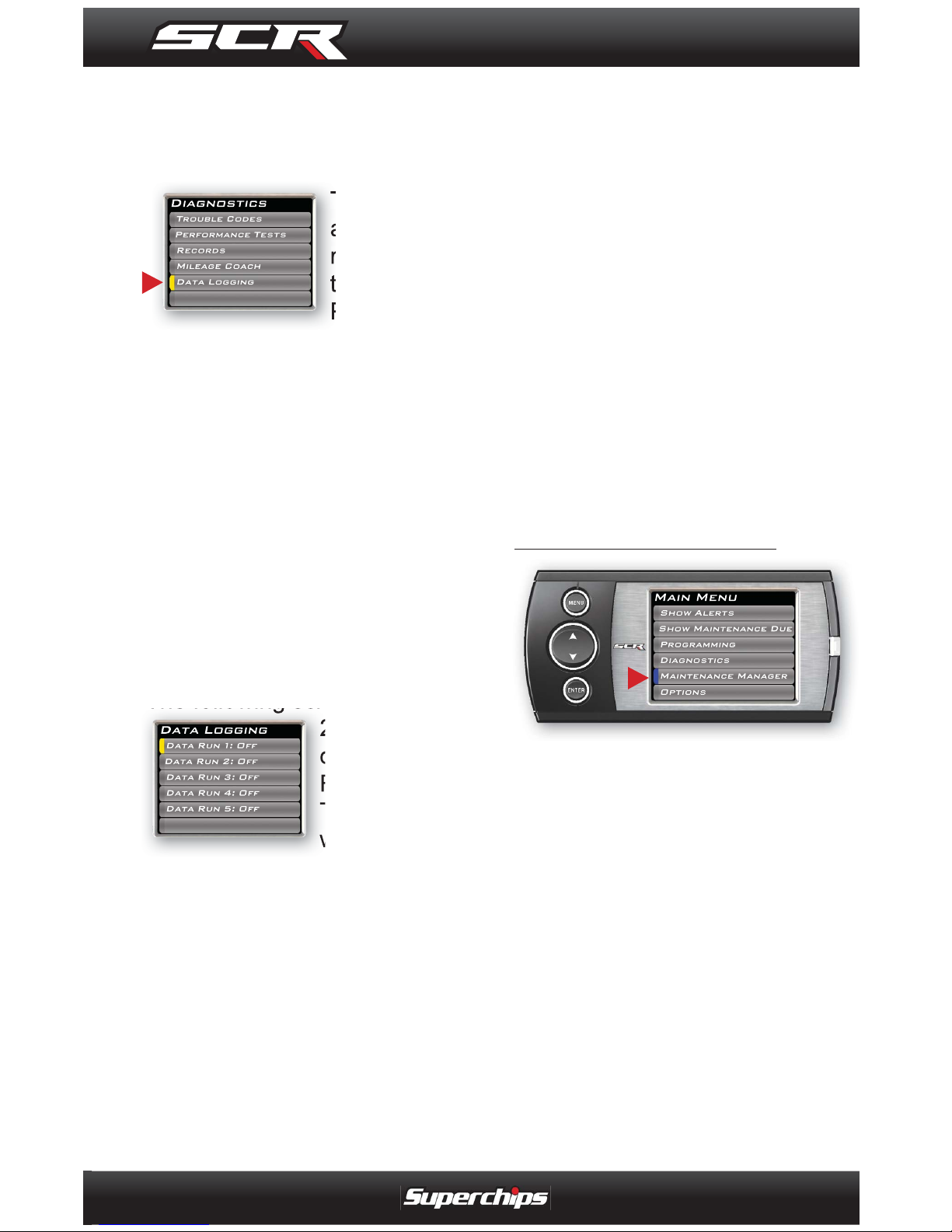
--DATA LOGGING--
This feature
allows you to
record all of
the available
PID data on
your device, so you can view it
at a later time.
(NOTE: The device also runs
background tasks which are
also recorded. This information can be ignored.)
To start the recording:
1. Open the Data Logging menu
located under the Diagnostics
menu.
The following screen will appear:
2. Choose one
of the 5 Data
Run options.
The data run
will turn “On”.
NOTE: Only one data run can
be turned on at a time.
3. Return to the Main Gauge
screen. The device is now in
recording mode.
4. Once you have recorded for
a desired period of time, return
to the Data Logging menu, and
choose the same data run as
before. (This will turn the data
run “Off” and stop the device
from recording. The recorded
information will be stored for the
My Style software to retrieve
later on).
NOTE: If you turn the same
Data Run back “On” the previous data will be erased, and
a new recording session will
begin. If the indicator light
is red, there is currently a
recorded fi le associated with
that run.
MAINTENANCE MANAGER
The Maintenance Manager
calculates the odometer value
of your vehicle using the vehicle
speed and time.
NOTE: The Maintenance Manager odometer reading may
become out of sync with the
actual dash odometer reading.
You may need to periodically
update the Maintenance Manager’s odometer value. It is
important to note that the SCR
only tracks miles traveled
when the main gauge screen
Page 18
OPERATING INSTRUCTIONS
18
is being displayed. If you are
in the menus while driving,
your miles are not calculated.
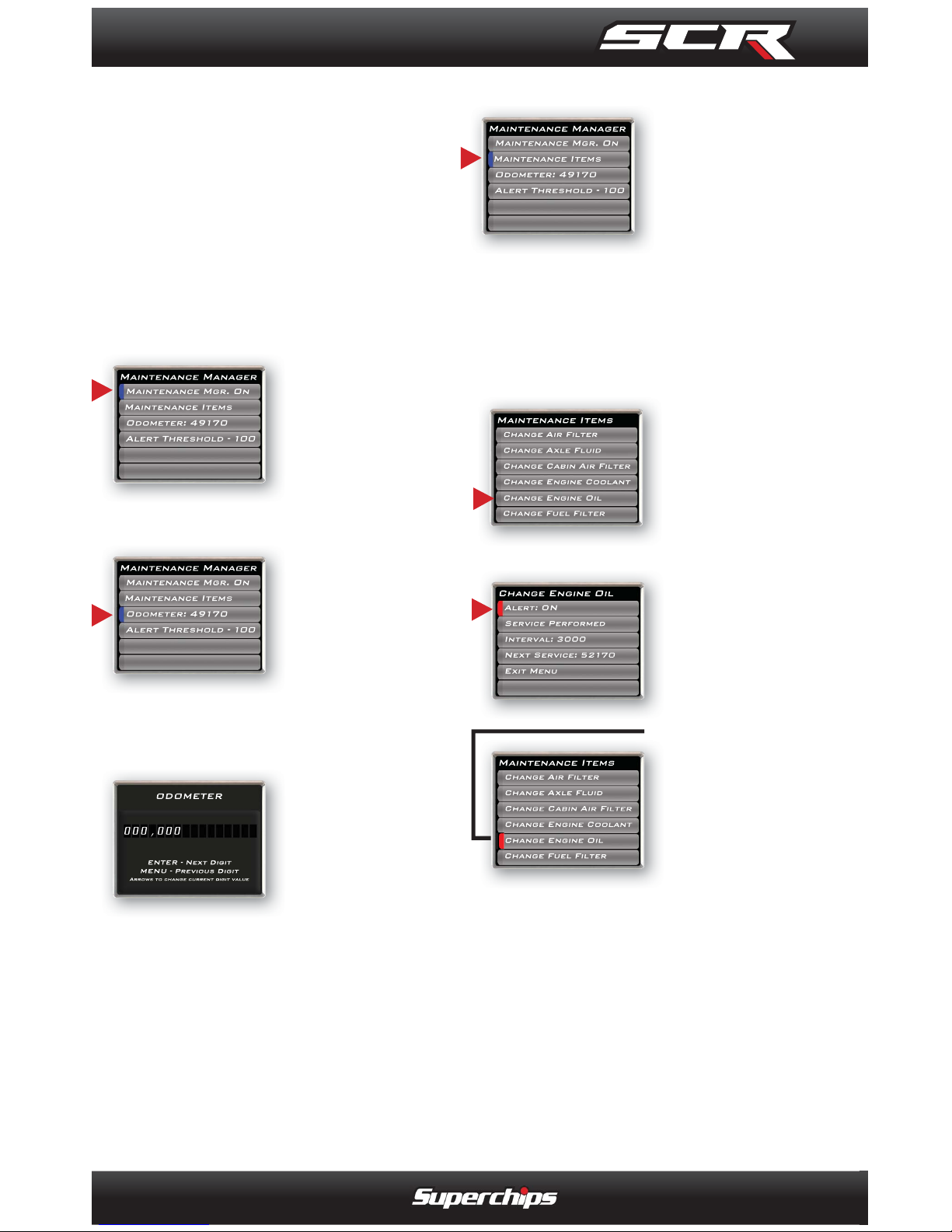
--ODOMETER SETUP--
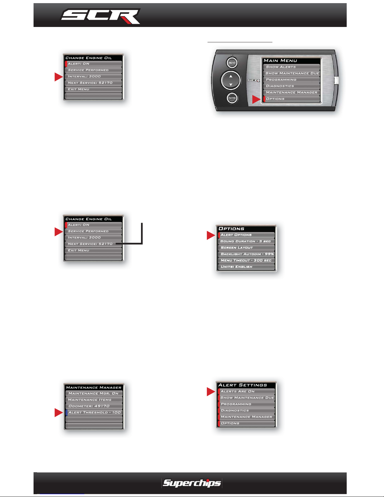
1. Locate the “Maintenance
Manager” by entering the “Main
Menu”.
2. Turn “ON” the Maintenance
Manager. (If
it is turned off,
you will not be
notifi ed when
service is
due.)
3. Choose
“Odometer” to
set your current Odometer
reading.
The following screen will appear:
4. Use the
Arrow buttons
to adjust the
values up or
down.
5. Press the Enter button to
move to the next Digit.
6. Once all digits have been en-
tered, the Maintenance Manager
screen will reappear showing
your entered value.
7. Once the Odometer is entered and displayed, chose
the “Maintenance Items”
option, and
refer to the following section.
--MAINTENANCE SETUP--
1. Chose the item you would
like to maintain. For demonstration purposes, the “Change
Engine Oil”
item will be
used in this
example.
2. Turn the ALERT ON.
NOTE: Once
a Maintenance Item
is turned
on, the Alert
Status Box
to the left of
the item will
light up. If
it is green,
the item is
not yet due for service. If it is
yellow, the item is about to be
due and within the specifi ed
Alert Threshold. If it is red,
the item is due for service. If
it remains black, the item is
not turned on. This all depends on the following settings.
Page 19
OPERATING INSTRUCTIONS
19
3. Setup the interval value. The
3000 in the example will remind
you every 3000
miles to change
the engine oil.
NOTE: Refer to your vehicle
user manual to determine
what value is recommended
for each Maintenance Item.
4. Select the “Service Performed” option. This will automatically set the “Next Service”
value.
NOTE: Each
time your vehicle is serviced,
the “Service Performed” option will need to be selected to
set the “Next Service” Value.
3. The “Exit Menu” option will
bring you back to the main
gauge screen.
--ALERT THRESHOLD--
The Alert
Threshold
value allows
you to set how
many miles
ahead of time you want your
Maintenance Manger to alert
you that an item is due.
OPTIONS MENU
The Options menu contains
items that will allow you to customize the device settings, as
well as change the alert settings
to best fi t your needs.
--ALERT OPTIONS (SETTINGS)--
The Alert Options screen allows you to turn the alerts on or
off both collectively and
individually. It
also lets you
set the alert
values for each of the available
PIDs.
To turn alerts on:
1. Select Alert Options from the
Options menu.
2. Select Alerts are Off/On and
press enter. This will affect the
entire alert
system as a
whole.
Page 20
OPERATING INSTRUCTIONS
20
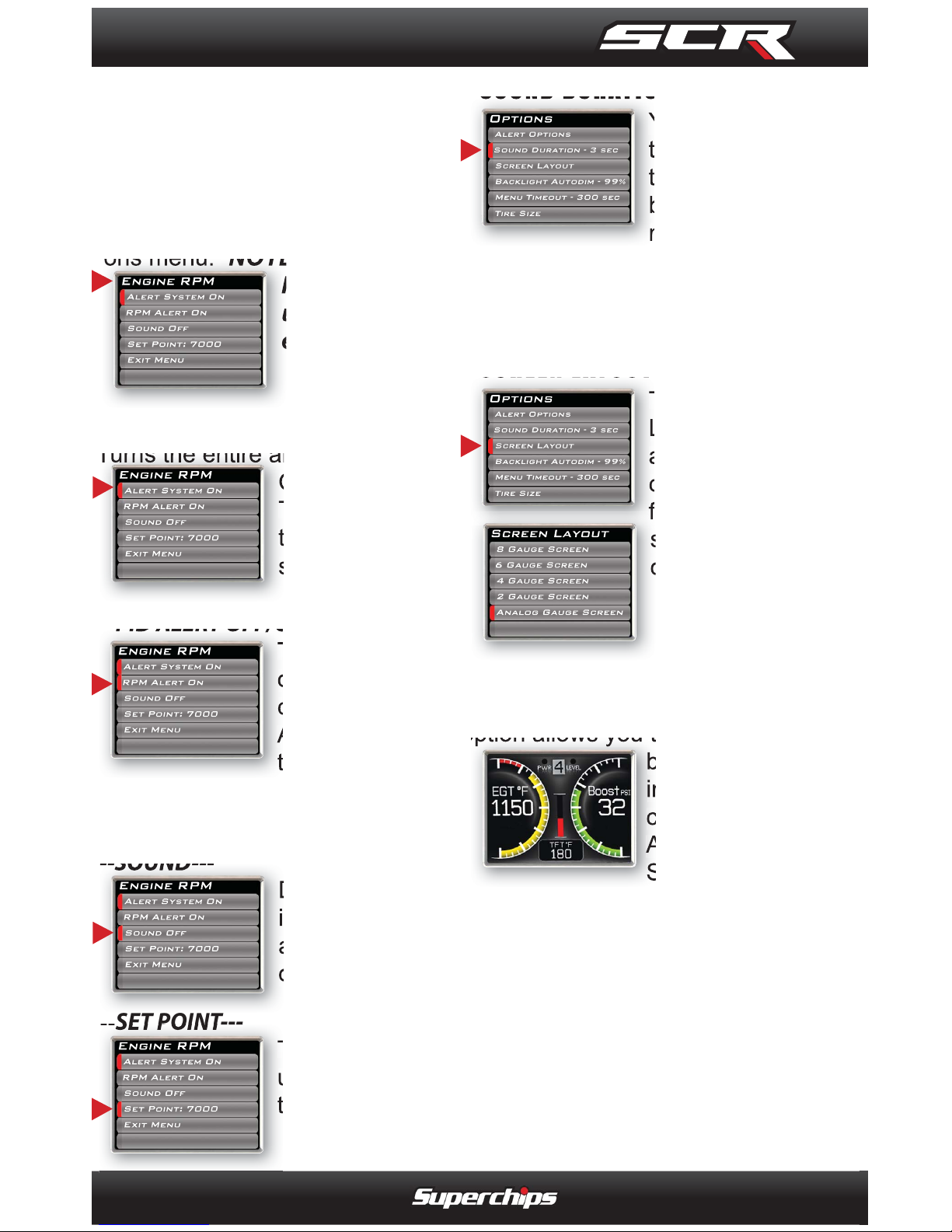
NOTE: To individually disable or enable an alert, or to
change the alert follow these
instructions:
1. Select a PID in the Alert Options menu. NOTE: Engine
RPM is being
used for this
example.
---ALERT SYSTEM OFF/ON---
Turns the entire alert system
OFF or ON.
This disables
the alerts and
sound.
---PID ALERT OFF/ON---
This turns OFF
or ON the specifi c PID alert.
Any other PID
that is turned
on, will not be affected, and
remain turned on.
---SOUND---
Deals with
individual PID
alert sounds
only.
---SET POINT---
This value is
used to trigger
the alert.
--SOUND DURATION--
You can adjust
the duration of
the alert sound
by using this
menu option.
Simply press the up/down arrow
until you have the desired sound
length in seconds.
--SCREEN LAYOUT--
The screen
Layout menu
allows you to
choose from
fi ve different
screen layout
options.
The Analog Gauge Screen is
set as the default. This gauge
option allows you to change the
background
image. After
choosing the
Analog Gauge
Screen option, you will be asked to toggle
through the different backgrounds.
For more information on how
to create custom backgrounds,
refer to the MyStyle section of
this manual.
Page 21
OPERATING INSTRUCTIONS
21
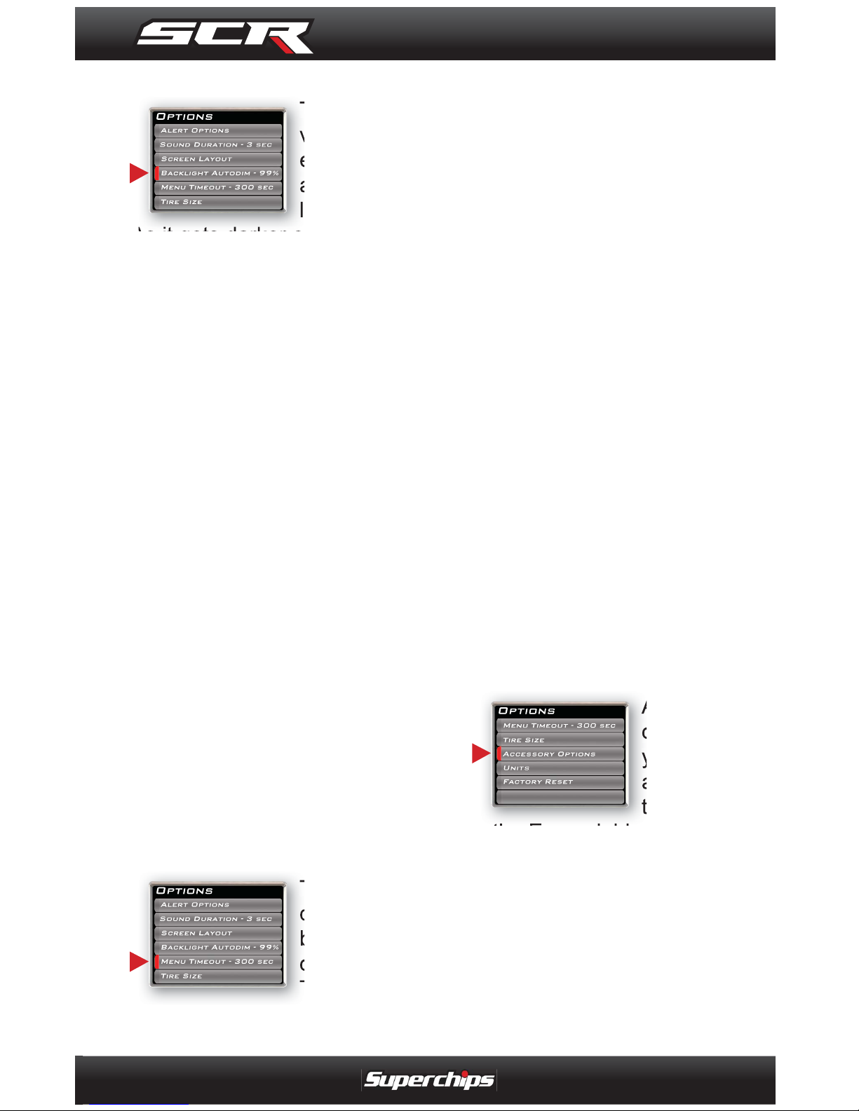
--BACKLIGHT AUTODIM--
The SCR device has been
equipped with
an ambient
light sensor.
As it gets darker outside, the
device will automatically dim the
screen for easier viewing. The
Auto Dim feature allows you to
set how much the screen will
dim.
NOTE: It’s best to make this
adjustment at night so you
can verify the screen brightness is correct. You’ll need
to return to the main display
screen after setting
the Autodim percent in order to see
the changes.
The default is set at 99%. This
max setting provides the largest
range between the brightness of
the screen during the daylight,
and the darkness of the screen
at night. A 1% setting will provide the same brightness during
the day and night.
--MENU TIME-OUT--
The SCR
device has a
built in timeout feature.
The purpose
of this time-out is to prevent the
unit from staying powered up for
excessive amounts of time. If
you leave the device in a menu
option, and turn off the vehicle,
the device will stay in the menu
(for 300 seconds by default).
After the 300 seconds are up, it
will automatically return to the
main gauge screen and power
off. The same will happen if the
device is left in a menu while
the vehicle is running or the key
is on (it will return to the main
gauge screen, but not turn off).
CAUTION: This function only
applies to menu screens. If
you are viewing a parameter
(PID) adjustment screen, the
device will not time out. If you
do not exit these screens, the
device will not power-off and
may discharge the vehicle’s
battery.
--ACCESSORY OPTIONS--
Accessory
options allow
you to adjust
add on fea-
tures such
as the Expandable Accessories
System (EAS). As other accessories are added, additional
options will also be added.
Page 22
OPERATING INSTRUCTIONS
22
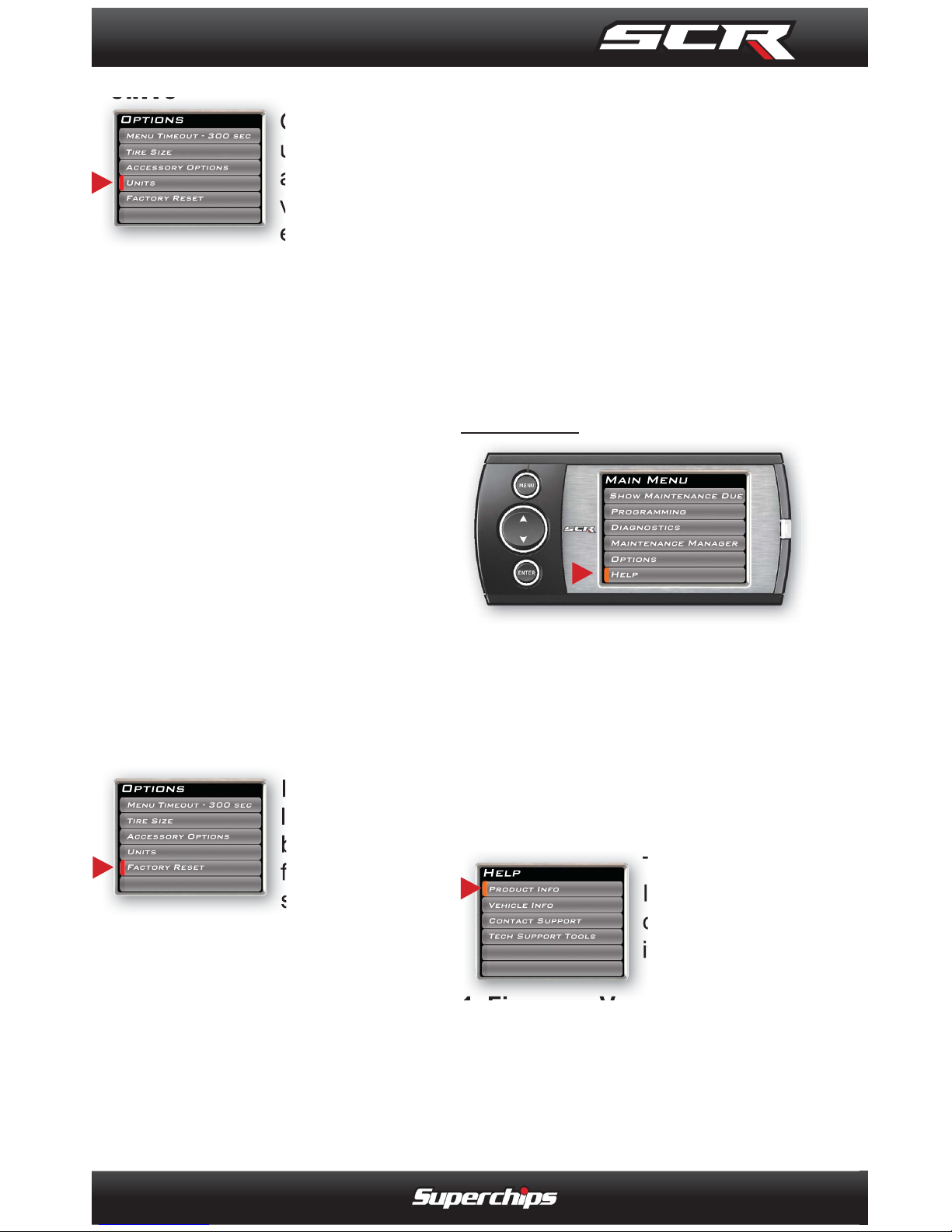
-- UNITS--
Changing the
unit option
allows you to
view PIDs in
either Metric
or English on the main gauge
screen. Vehicle Speed, for example, may be viewed as either
MPH or KPH. Temperature
PIDs such as Engine Coolant
Temperature may be viewed as
either Fahrenheit or Celsius.
CAUTION: If you set up your
units in either English or Metric, the alert value will be the
same for both. If you change
from one unit to another, you
will need to setup the alert
values accordingly. For example, 100 MPH is not the
same as 100 KPH.
--FACTORY RESET--
If you would
like to revert
back to the
factory default
settings, simply select Factory Reset
and choose YES or press
ENTER.
Many settings will be returned
back to the default setting as
they were when the unit was
new. Any changes you’ve made
to the alerts, the gauge screen
displays, etc will be returned to
the default settings provided by
Superchips.
NOTE: Factory Reset will not
return the vehicle to stock
from a programmed Power
Level. See Programming
Power Levels section for
instructions to return to stock
power level.
HELP MENU
The Help Menu contains useful
information about your device,
and the vehicle it is being used
on. It also contains Superchips
Contact Information, and Technical Support tools.
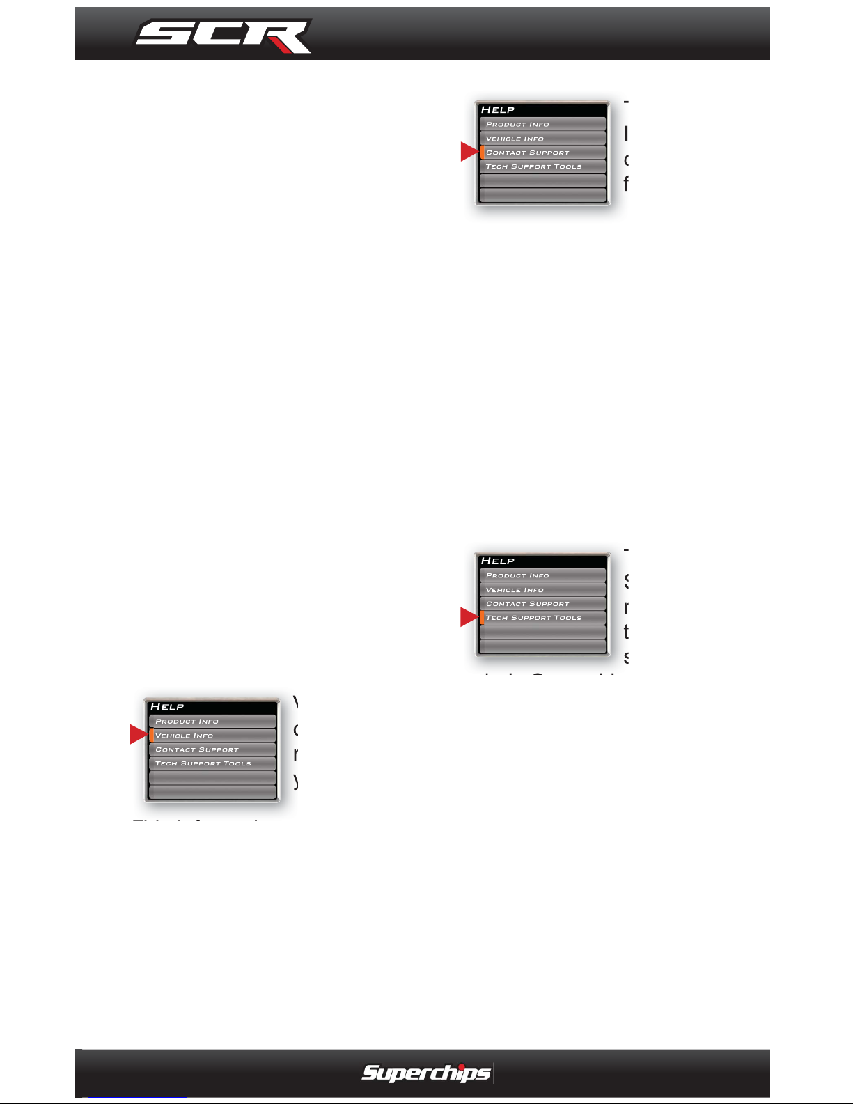
--PRODUCT INFO--
The Product
Info screen
contains fi ve
items:
1. Firmware Version
2. Calibration Version
3. Application Version
4. FPGA Version
5. Serial Number
Page 23
OPERATING INSTRUCTIONS
23
NOTE: The Serial Number is
assigned to your particular
device and is used in the software update process by Technical Support.
Occasionally, Superchips will
release updates with improved
functionality for both Firmware
and Calibrations. Each of these
updates are labeled with a
number, the number shown in
this menu represents the version
that is currently on your device.
If you have an EAS device
installed on your vehicle and
plugged into your device, another Product Info screen will be
made available:
1. EAS Firmware Version
2. EAS Serial Number.
--VEHICLE INFO--
Vehicle Info
contains information about
your vehicle.
This information will give
Superchips Technical Support
the specifi cs of your vehicle.
--CONTACT INFO--
The Contact
Information
contains the
following:
1. Superchips’ web site URL
2. Superchips’ address
3. Technical Support’s e-mail
4. Technical Support’s ph. #
This information will be useful if
you need to contact Superchips
for warranty claims, sales information, upgrade information or
any other technical questions/
inquiries.
--TECHNICAL SUPPORT TOOLS--
The Technical
Support Tools
menu contains
tools made
specifi cally
to help Superchips’ Technical
Support representatives help
customers when they are experiencing problems with their vehicle or device. This menu should
only be used when requested by
Superchips Technical Support
personnel.
Page 24
OPERATING INSTRUCTIONS
24
NOTE: It is important to unplug all power consuming
devices (plugged into the
cigarette lighter or power
outlets). If you are receiving
errors or your display is stuck
on the “Uploading bootloader” screen, refer to the trouble
shooting guide at the back of
this manual for more information.
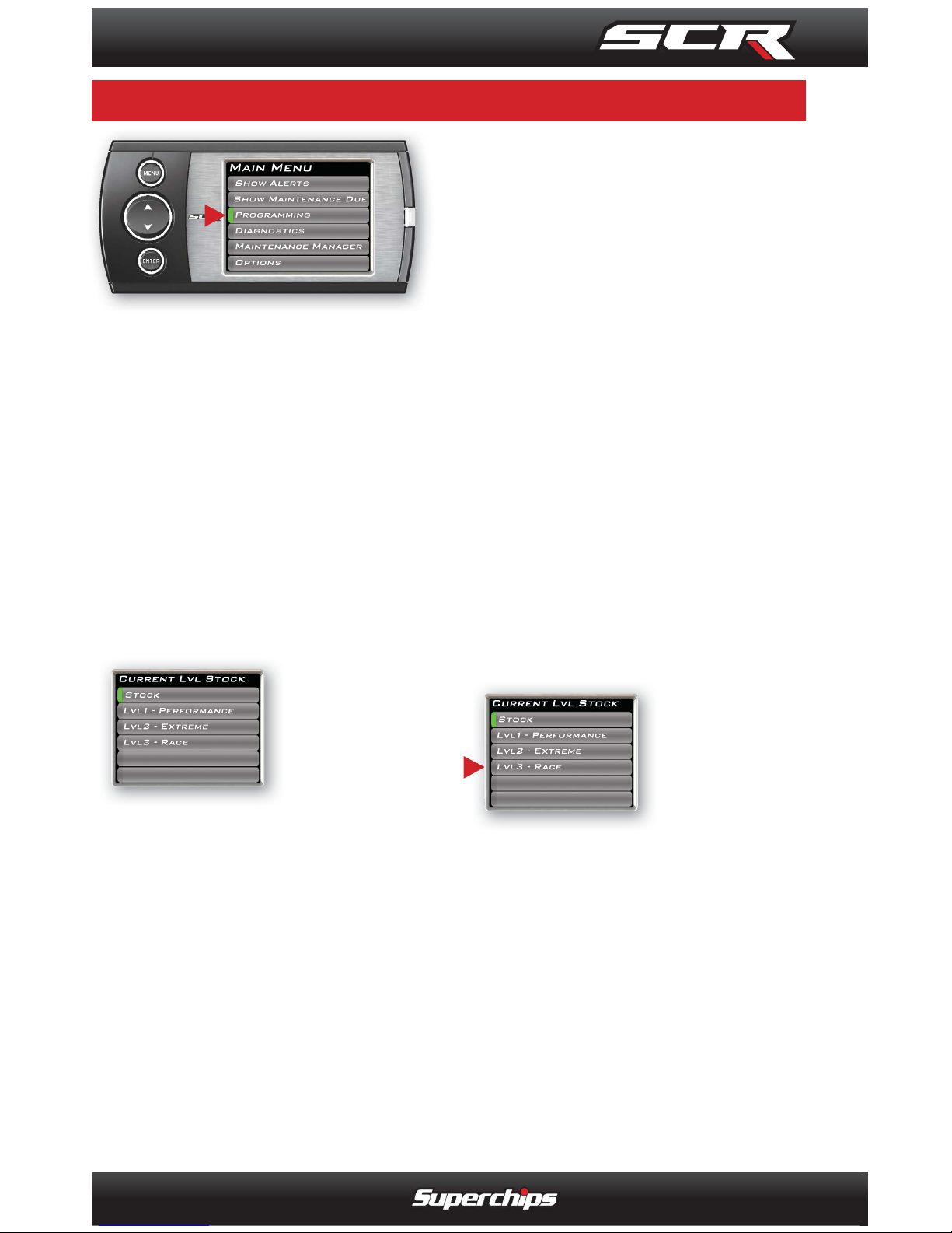
--PROGRAMMING LEVELS--
The SCR
device comes
ready with
power levels
that can be
programmed into your vehicle’s
Power Control Module (PCM)
NOTE: Some power levels
are specifi c to certain vehicle
models. Availability may vary.
Stock = This will program your
vehicle back to stock.
Performance = This program
requires the use of 87+ octane
gas.
91 Performance = This program
requires the use of 91+ octane
gas.
93 Performance = This program
requires the use of 93+ octane
gas.
Extreme = This program
requires 91+ octane gas.
Race = This program
requires 93+ octane gas.
Extreme Pulley = This program
is available only for GT500’s
with a 4lb pulley modifi cation.
91+ Octane gas is required.
To Program to a Level:
1. Select the
power level
that best suits
your needs.
2. Follow the
instructions on the screen. If
you choose to Create a custom
program, continue to the Cus-
tom Options section.
CAUTION: Only program while
the vehicle is parked and
away from traffi c, or where the
vehicle may impede access or
exit. Programming will take
several minutes and the vehicle can not be started.
P R O G R A M M I N G T H E V E H I C L E
PROGRAMMING THE VEHICLE
Page 25
OPERATING INSTRUCTIONS
25
CAUTION: Do not combine,
or “stack” chips (modules) to
gain more horsepower. The
chips could be incompatible
and result in power-train failure or create dangerous conditions leading to a serious or
fatal accident.
--- CUSTOM OPTIONS---
Custom options allow you to
change non-stock parameters.
USE CURRENT SETTINGS
This option will use the previously selected options.
RESET ALL V ALUES
This option will restore all of the
settings back to factory defaults.
TIRE SIZE
This option will allow you to
select a new tire size if you’ve
changed the factory tires.
GEAR RATIO
This option will allow you to
select a new gear ratio if you’ve
changed the factory gears.
AXLE RATIO
This option will allow you to
select a new axel ratio if you’ve
changed the factory axle.
SPEED LIMITER
This option will allow you to
adjust the factory speed limiter
higher or lower than the factory
set speed limiter MPH.
NOTE: Removal/adjustment
of the factory speed limiter is
intended for use at a closed
circuit, legally sanctioned racing environment. If this custom option is used for purposes inconsistent with the
product’s intended function,
and violates the product’s
intended use, the product’s
warranty is no longer valid.
Superchips is not responsible
for, or liable for the consequences of improper product
use.
WARNING: If you drive
on public roads after removal
or adjustment of the speed
limiter, you must still obey all
driving laws, including adhering to posted speed limits.
To drive at racing speeds on
public roads seriously endangers you, your passengers,
and others nearby. Even if
racing in a legally sanctioned
racing environment, it is your
responsibility to ensure your
tires and other vehicle components are rated to travel at
increased speeds.
Page 26
OPERATING INSTRUCTIONS
26
USING MYSTYLE
Create and add your own custom backgrounds using the
unique MyStyle™ Software.
Mystyle can be downloaded
from the Superchips website.
To change the background
image:
1. Press the Menu Button to
open the main menu.
2. Select the Options menu.
3. Select Screen Layout under
the Options menu.
4. Choose the Analog Gauge
Screen option from the main
menu.
5. When the Analog Gauge
screen displays, you will have
the option to choose from 10 different screen backgrounds.
6. Scroll through options using
the Up/Down button and then
press the Enter button.
C U S T O M I Z A T I O N
CUSTOMIZATION
Page 27
INTERNET UPDATES
27
Fusion Software allows the user
to update their device to the
latest version of fi rmware and
calibration fi les. Download the
Fusion software from:
http://www.superchips.com/
or
http://www.fusionupdate.com/
NOTE: Before you connect
your device to your PC be
sure to install both the SOFTWARE and the DRIVERS
included in the download.
During the installation you
will be prompted to install the
drivers...Choose yes.
USING FUSION SOFTWARE
CAUTION: The SCR device
cannot be plugged into the
vehicle’s OBDII port and your
computer’s USB port at the
same time.
NOTE: Be sure to return your
vehicle to stock before connecting the device to Fusion.
1. Click the Fusion icon on
your PC desktop.
2. If you have not yet created an
account, click on “Create a New
User”. You will then be directed
to a web page to create your
login information.
NOTE: After entering your information, a password will be
sent to the e-mail address you
provide. Be sure your e-mail
account doesn’t block e-mails
from www.fusionupdate.com.
3. Enter your e-mail address
and password on the login
screen of the Fusion Software.
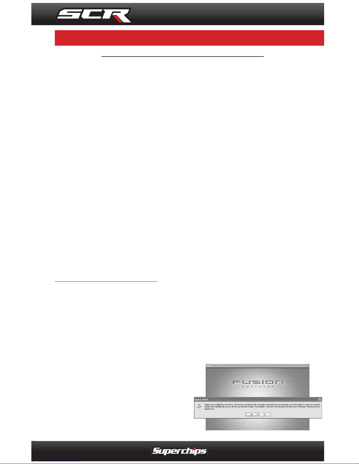
4. The computer will prompt you
to connect the device using the
USB cable. After connecting
the device, you’ll see a screen
pop-up.
5. Click Y es to continue with the
update.
***REQUIRES INTERNET CONNECTION***
F U S I O N S O F T W A R E U P D A T E S
FUSION SOFTWARE UPDATES
Page 28
INTERNET UPDATES
28
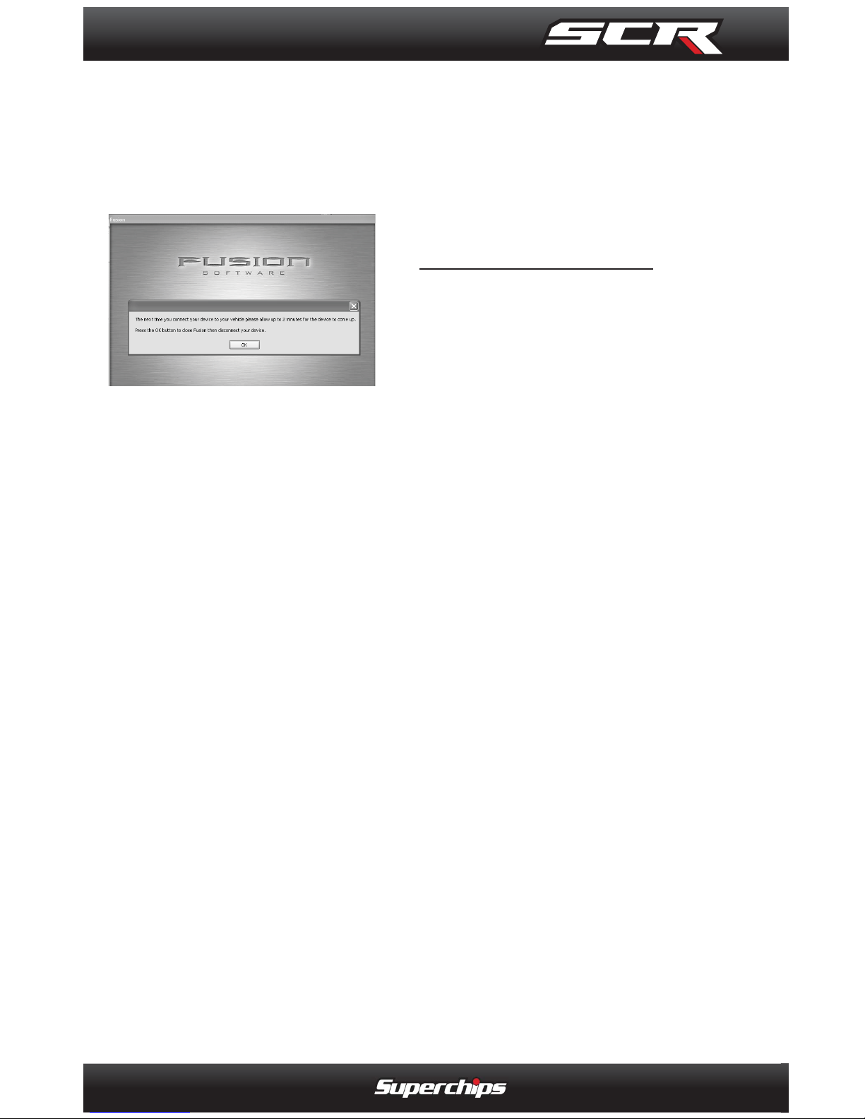
After you’ve selected yes, the
Fusion software will automatically update the device. Once
it’s completed, you’ll see the
following screen.
6. Click OK and the update will
be completed. You’ll now have
the latest Firmware, and Calibrations on your device.
When your device is connected
to Fusion, the device model, Lvl,
Bootloader, Firmware, Calibration and Serial Number are all
displayed at the bottom of the
screen. These numbers will be
useful to quickly view the state
of your device, and whether or
not it is currently programmed to
a vehicle.
• MODEL : The model number
for your device.
• LVL : The currently programmed level.
• BOOTLOADER : The boot
loader version currently on
your device.
• FIRMWARE : The fi rmware
version currently on your
device.
• CALIBRATION: The calibration version currently on your
device
• SERIAL NUMBER : The serial number assigned to your
device
PROGRAMMING ERRORS
--UPDATE REQUIRED--
Fusion is designed to help
the development team
at Superchips support
new vehicle calibrations.
When you connect your
device to the vehicle, the fi rst
step it takes is identifying your
vehicle’s stock fi le.
If the stock fi le isn’t currently
supported:
1. The device will display a
screen alerting you that the
stock fi le is not yet supported.
2. It will then prompt you to
press a button in order to read
and save the stock fi le.
3. Once the device has saved
the stock calibration, it will
prompt you to connect the de-
vice to Fusion.
4. Fusion will ask you if you
want to upload your vehicle’s
stock fi les to our server. Choos-
ing Yes will upload the fi les to
the server, and alert the devel-
Page 29
APPENDIX
29
opment team. This will help the
development team provide support for your vehicle’s calibration
as quickly as possible.
--NON-STOCK CONDITION--
During programming, the device
will read the stock fi le on your
vehicle and compare it to a corresponding stock fi le that has
been verifi ed by Superchips. If
there is a mismatch, the device
will alert you, and display the following message:
“ Non-stock condition detected. This is most likely
because your vehicle has
been programmed with a competitive product. It is recommended that you return your
vehicle to a stock condition
with the product that changed
it. Alternatively, you can plug
your device into your computer and it will load the necessary fi les onto your device to
return your vehicle to stock.”
If you don’t have the competitive
product that programmed your
vehicle:
1. Connect the device to Fu-
sion (via USB connector) where
you’ll be prompted to download
the correct stock fi les.
2. Once downloaded, simply
connect the device to your vehicle (via OBDII), and the device
will program the verifi ed stock
fi les to your vehicle.
Page 30
APPENDIX
30
Tip: Programming your vehicle may expose existing defects in your
PCM that could disable your vehicle. It is advised that you do not
program in remote locations in case of failure. Vehicle manufacturers do not recommend programming in extreme temperature.
Please see your vehicle service manual to ensure that programming is being done in accordance to the original equipment manufacturers specifi cations.
Tip: Keep in mind that the SCR is a high performance product and
that not all vehicles deliver the exact same power output when programmed with the SCR. It is recommended that you select a program that will best fi t your needs. Keep in mind the condition and
tolerances of your vehicle when selecting a suitable power level.
Tip: If any problems persist, contact Superchips Technical Support.
Please have the product Serial Number and Vehicle Information
prior to calling Technical Support. This will help ensure quick and
accurate support.
Tip: When taking your vehicle to the dealership to get the oil
changed or to get other work done, it is always a good idea to
program the vehicle to stock before taking it in for service. In many
cases, the dealership has new updates for the vehicle, and consequently will update the vehicle’s computer. If the vehicle is programmed to a power level, the dealership update will over write the
programming and lock the device. Always program the vehicle to
stock, and update the product on Fusion while it is out of the vehicle to ensure that the software on the SCR is up to date with the
software the dealer installs in the vehicle.
T I P S
TIPS
Page 31
APPENDIX
31
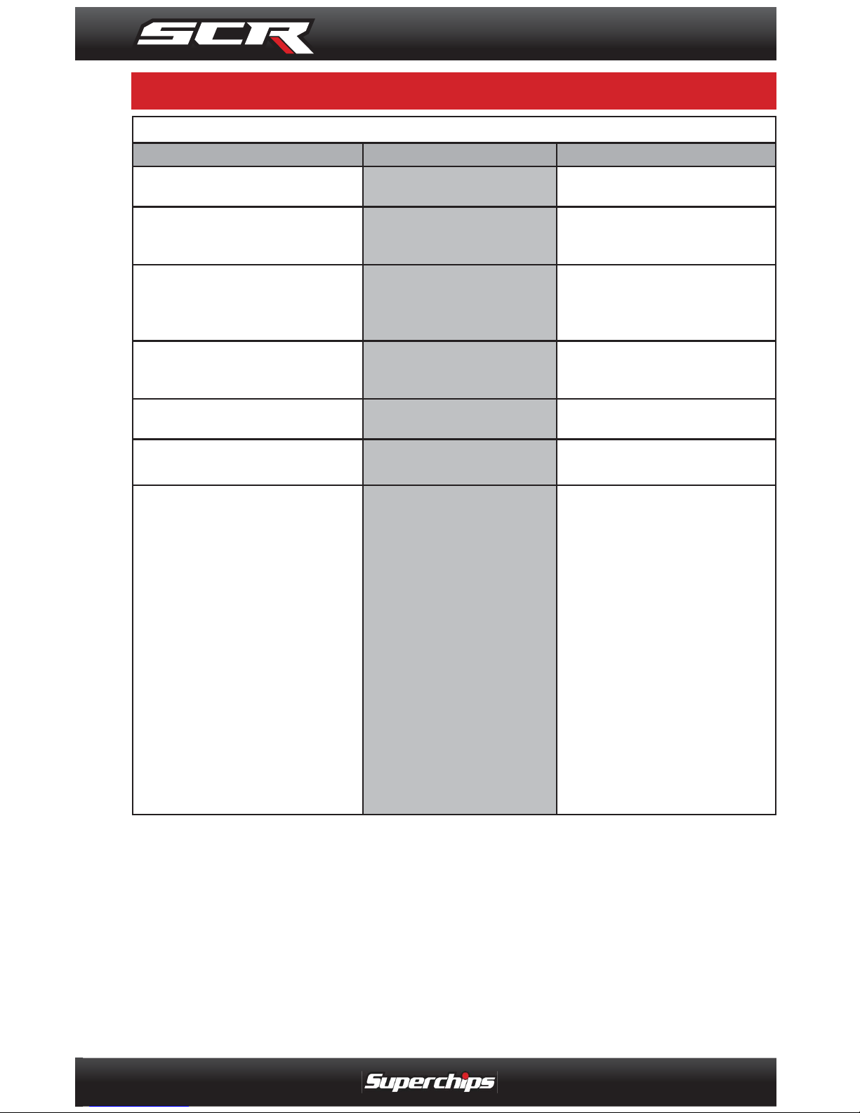
TROUBLE SHOOTING GUIDE
SYMPTOM POSSIBLE CAUSE SOLUTION
Display beeps for two seconds (long beep) The unit is too hot from being in the
direct sunlight
Once the device cools down the screen will
turn itself on
No display when the key is in “on” position The unit will not wake up with the
key in the “on” position until any
button is pressed
Touch the screen or start the vehicle, if this
does not turn the screen on then you will
need to call technical support
Vehicle does not start after programming The calibration may have not written
correctly
Select “Return to stock” from the programming menu. Then, Program back to stock.
Now, try to start the vehicle again. If the
problem continues contact tech support
Fusion drivers will not install correctly The drivers were not successfully
installed by the automatic installer
Manually install the drivers, technical
support can provide you with instruction
on how to do this
Display beeps quickly Possible device malfunction Update the device using the fusion
software
Unit will not power on after vehicle is started
or after screen or buttons are pressed
Typically this issue is caused by a
blown OBDII/Cigarette Lighter Fuse
Replace fuse and test unit again
Programming errors:
1. Your device gets stuck on the “Uploading
Bootloader” screen
2. An error is displayed: “ERROR-We could
no upload the bootloader to the vehicle...”
3. If you are constantly asked to make sure
your key is on.
4. Error displayed after your device shows
blank gauges and says that it is loading. The
error will be displayed as “Cannot communicate with vehicle, ensure the key is in the
on position...”
Sometimes programming can be
disrupted by installed aftermarket devices that are tapped into the vehicle
communication lines. These may
include but are not limited to aftermarket radios, chime boxes, remote
starters, ect.
Also, any power consuming devices
should not be plugged into the cigarette adapter during the programming
process. Fluctuations in power may
disrupt the programming process.
The following solutions are good fi rst
steps to getting around these programming
errors. If these steps do not solve your
problem, please contact Tech Support:
Fuses: ( CAUTION: Always turn the key
off while unplugging fuses).
1. Remove fuses connecting radio, radio
amplifi er, satellite radio, remote starter,
or any other aftermarket device you have
installed on your vehicle.
Power:
1. Close all doors during programming.
2. Do not operate electrical accessories
(radio, windows, wipers, ect.)
3. Remove any devices plugged into the
cigarette lighter or any other auxiliary
power port.
T R O U B L E - S H O O T I N G
TROUBLE-SHOOTING
Page 32
APPENDIX
32
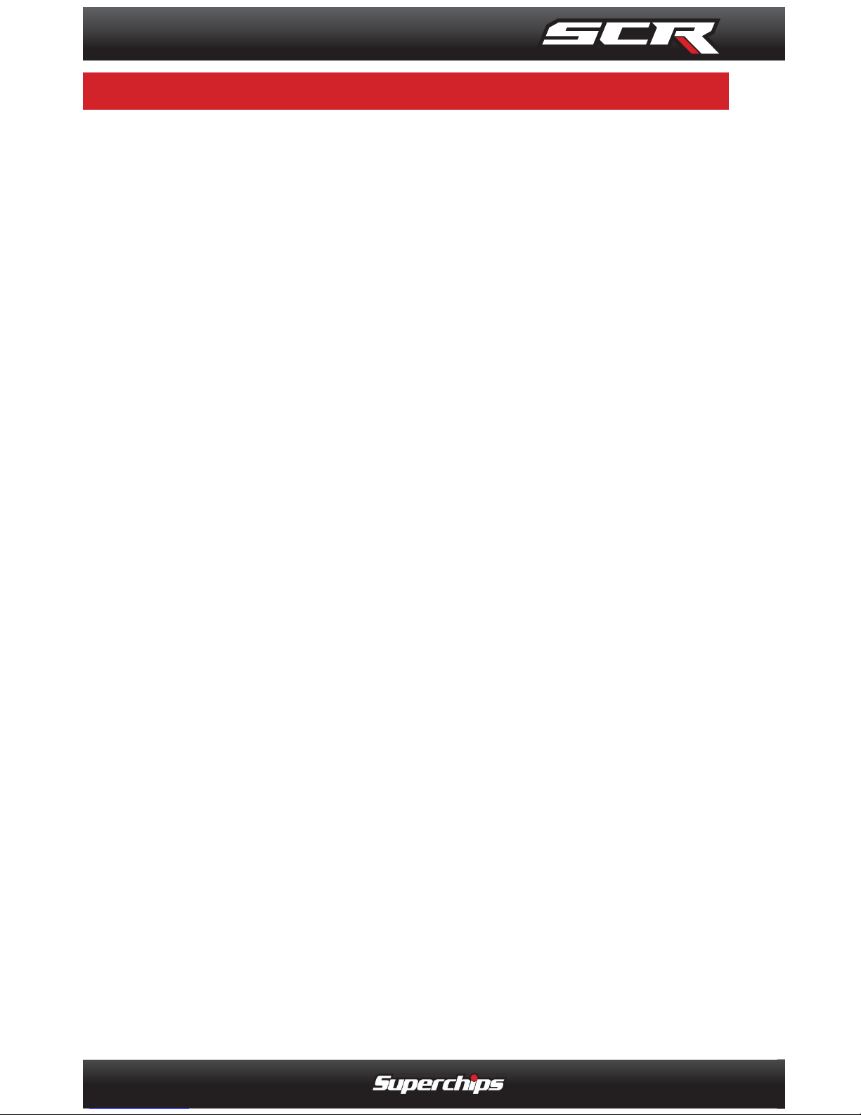
ACT = Air Charge Temp
ACV = Air Control Sensor
AOD = Automatic Overdrive Transmission
APP = Accelerator Petal Position
BAT = Battery Voltage
BCM = Body Control Module
BOO = Brake On/Off Switch
BP = Barometric Pressure Sensor
CCD = Computer Controlled Dwell
CCO = Converter Clutch Override
CDR = Crankcase Depression Regulator
CEL = Check Engine Light
CFI = Central Fuel Injection
CHT = Cylinder Head Temperature
CID = Cylinder Identifi cation Sensor
CKP = Crank Position Sensor
CMP = Cam Position Sensor
CPS = Crankshaft Position Sensor
DTC = Diagnostic Trouble Codes
EAS= Expandable
Accessory System
ECA = Electronic Control Assembly
ECM = Electronic Control Module
ECT = Engine Coolant Temp
EDF = Electric Drive Fan Relay
EDIS = Electronic Distributor
EGO = Exhaust Gas Oxygen Sensor
EGR = Exhaust Gas Recirculation
EOT = Engine Oil Temperature
EVP = EGR Position Sensor
EVR = EGR Valve Regulator
FDM = Fuel Delivery Module
FPM = Fuel Pump Monitor
FRP = Fuel Rail Pressure
HEGO = Heated Exhaust Gas Sensor
IAT = Intake Air Temperature
ICM = Integrated Controller Module
IDM = Ignition Driver Module
ISC = Idle Speed Control
ITS = Idle Tracking Switch
IVS = Idle Validation Switch (Diesel)
KAM = Keep Alive Memory
KOEO = Key On Engine Off
KOER = Key On Engine Running
KS = Knock Sensor
LOAD = Engine Load
LOS = Limited Operation Strategy
LPD = Line Pressure Desired
LUS = Lock-up Solenoid
MAF = Mass Airfl ow
MAFV = Mass Airfl ow Sensor Voltage
MAP = Manifold Absolute Pressure
MAT = Manifold Air Temp
MCU = Microprocessor Control Unit
MIL = Malfunction Indicator Light
MPH = Miles Per Hour
OHC = Over Head Camshaft
OSS = Output Shaft Speed
PCM = Powertrain Control Module
PIP = Profi le Ignition Pickup
PSPS = Power Steering Pressure Switch
RPM = Revolutions Per Minute
SES = Service Engine Soon
SIL = Shift Indicator Light
SPARK = Spark Advance/Retard
SPOUT = Spark Output Signal
STAR = Self Test Automatic Readout
TAPS = Throttle Angle Position Sensor
TCM = Transmission Control Module
TFI = Thick Film Ignition System
TFT = Transmission Fluid Temperature
TGS = Top Gear Switch
TPS = Throttle Position Sensor
TQC = Torque Control
TSS = Turbine Shaft Speed
TTS = Transmission Temperature Switch
VAF = Vane Air Flow Sensor
VAT = Vane Air Temperature
VCT = Variable Cam Timing
VSS = Vehicle Speed Sensor
WAC = WOT A/C Cut-off Switch
WOT = Wide Open Throttle
C O M M O N L Y U S E D A C R O N Y M S
COMMONLY USED ACRONYMS
Page 33
INDEX
33
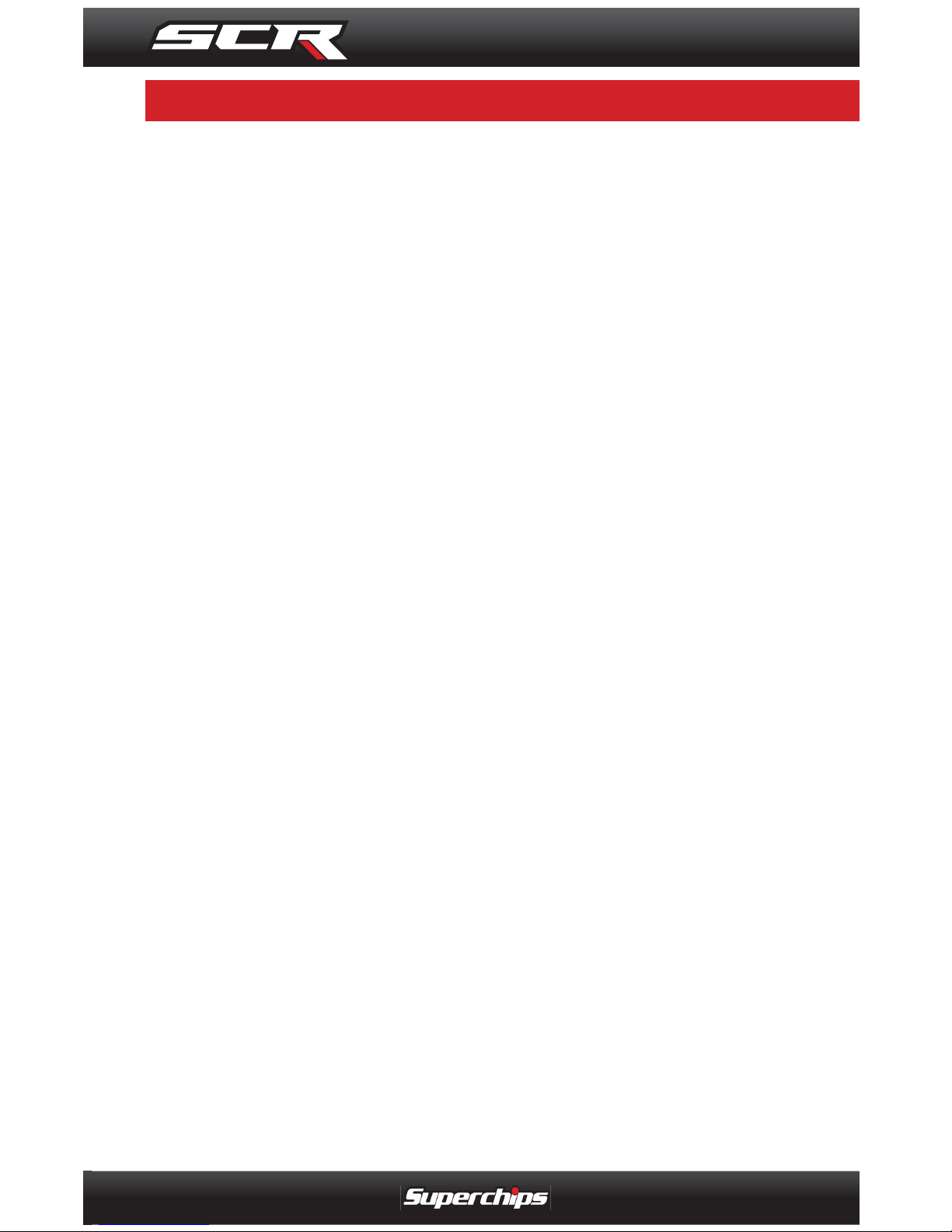
A
Alerts
Options 19
show alerts option 12
Threshold 19
viewing 12
C
Cable
OBDII 9
USB 9
C.A.R.B 8
Caution. See Safety
D
Data Logging 17
Diagnostics
Mileage Coach 14
Performance Tests. See Performance
Tests
Records 14
Trouble Codes. See Diagnostic Trouble
Codes (DTC)
Diagnostic Trouble Codes (DTC)
Clear DTCs 13
Read DTCs 13
E
EPA 8
F
Factory Reset 22
Fusion 27
G
Gauges. See also Screen Layout
Analog 10, 11
Digital 10, 11
M
Maintenance Manager 17
show maintnenance due 13
Mileage Coach 14
Mount
Windshield 9
Mystyle 26
O
OBDII. See Cable
P
Performance Tests 13
0 to 60 MPH 14
Quarter Mile 14
PIDs
gauge display 11
Programming 24
Custom Options 25
Errors 28
Levels 24
Non-Stock Condition 28
R
Registration 8
S
Safety 4, 5
Cautions 4, 7, 21, 22, 27, 31
Warnings 4, 5, 13, 24, 25
Screen Layout 20
Software. See Fusion; See Mystyle
Sound Duration 20
Stacking 5
T
Tuning. See Programming
affects on 7
U
Units 22
USB. See Cable
V
Vehicle Parameter ID’s. See PIDs
W
Warning. See Safety
Warranty
Limited 1 Year 6
Vehicle 6
I N D E X
INDEX
Page 34

INTENTIONALLY LEFT BLANK
Page 35

INTENTIONALLY LEFT BLANK
Page 36

1790 East Airport Blvd. | Sanford, FL 32773 | 888.227.2447
Rev. 00
www.superchips.com
Follow Us
 Loading...