

Page 1

Page 2
TABLE OF CONTENTS
STORAGE AND MAINTENANCE ............................................................................................... 3
BEFORE YOU BEGIN ................................................................................................................. 4
LIST OF COMPONENTS .....................................................................................................................4
BUTTON FUNCTIONALITY ................................................................................................................4
BASIC MENU LAYOUT ............................................................................................................... 5
DOWNLOAD IGNITION UPDATER TOOL .................................................................................. 6
PRODUCT UPDATES USING IGNITION .................................................................................... 8
OPTIONS ................................................................................................................................... 10
OPTIONS EXPLAINED .............................................................................................................. 11
READ DTC ................................................................................................................................. 12
CLEAR DTC .............................................................................................................................. 13
VIEWING GAUGES ................................................................................................................... 14
DATA LOGGING ....................................................................................................................... 15
DATA LOGGING RETRIEVAL .................................................................................................. 16
BATTERY VOLTAGE ................................................................................................................ 17
VEHICLE INFO .......................................................................................................................... 18
DEVICE INFO ............................................................................................................................ 19
SAFETY WARNING & CAUTION .............................................................................................. 20
SAFETY GUIDELINES .............................................................................................................. 21
LIMITED 1 YEAR WARRANTY ................................................................................................. 22
2
Page 3
STORAGE AND MAINTENANCE
NOTICE
It is NOT recommended to store your programmer in your vehicle in
extreme heat, direct sunlight or extreme cold (temperatures near or
below freezing). These conditions can cause malfunction or damage
to the programmer.
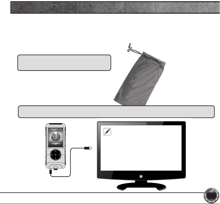
TIP: When you are not using your device,
place it in its protective bag. This will keep the
display from getting scratched.
TIP: Prior to using your device after a long period of non-use, use Ignition to update. This will ensure
that your device is up-to-date and contains all of the latest les and functionality.
Ignition
3
Page 4
OK
BEFORE YOU BEGIN
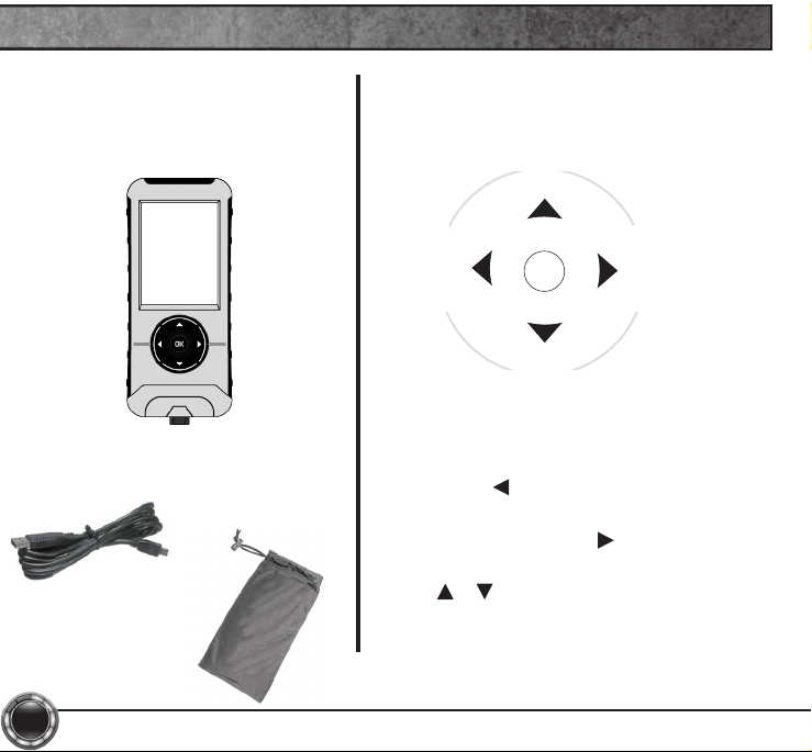
LIST OF COMPONENTS
DISPLAY DEVICE
USB CABLE
4
PROTECTIVE
BAG
BUTTON FUNCTIONALITY
Left
Back
Exit
NAVIGATING TIPS:
• To move back to the previous menu,
press the button.
• To move forward to the next menu, you
can press either OK or
enter the highlighted option.
• The & buttons are used to select
menu options, as well as adjust values for
certain features.
Up_Increase
Down_Decrease
Forward
button to
Right
Next
Page 5
BASIC MENU LAYOUT
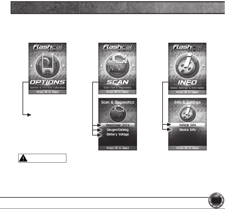
Some of the menu options or features displayed in this manual are
vehicle specic, and may not be available for your make and model.
Adjustable Options
WARNING
Misapplication or misuse of this product could lead to a serious or
fatal accident. Comply with all safety information in this manual, and
your vehicle owners manual. Follow safety, installation and operating
instructions in this User Manual to assure proper use.
5
Page 6
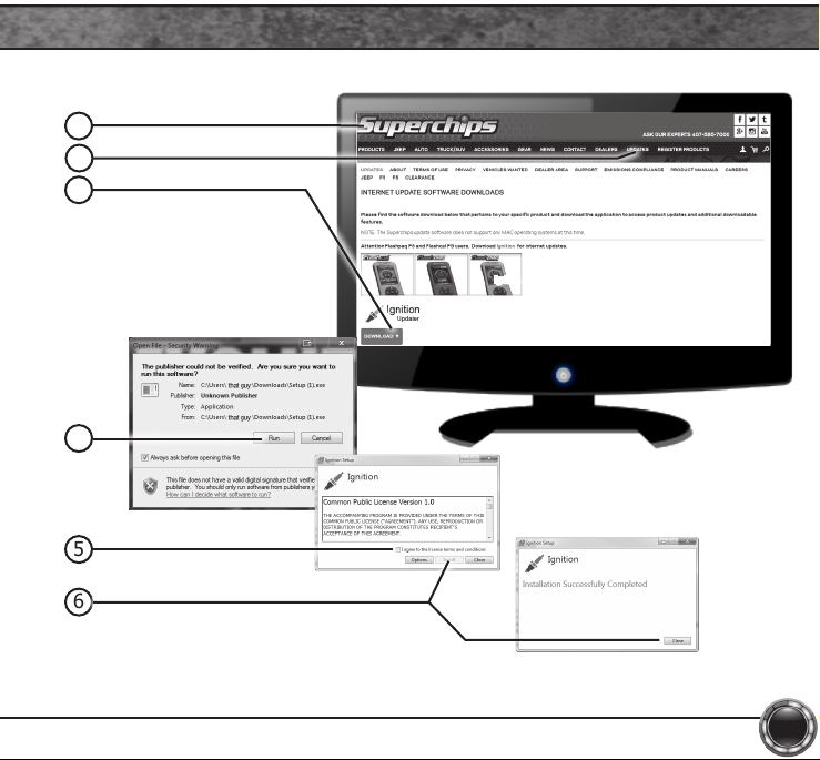
DOWNLOAD IGNITION UPDATER TOOL
1 Go to: www.superchips.com
2 Click the UPDATES tab located at the top of the page.
3 Click the Download button to download Ignition.
4 Click the Run button on the pop-up menu.
5 Read and click the box to accept the license agreement terms.
6 Click the Install Button, then the Close button once the download is complete.
7 Double-click the Ignition desktop icon.
8 Fill out the registration form.
9 Refer to the next section for performing product update.
TIP: Use a wired internet connection vs. wireless, air card, or satellite connections. This will minimize
potential connection issues that may affect the update process.
6
Page 7
1
2
3
Ignition
4
5
6
7
Page 8
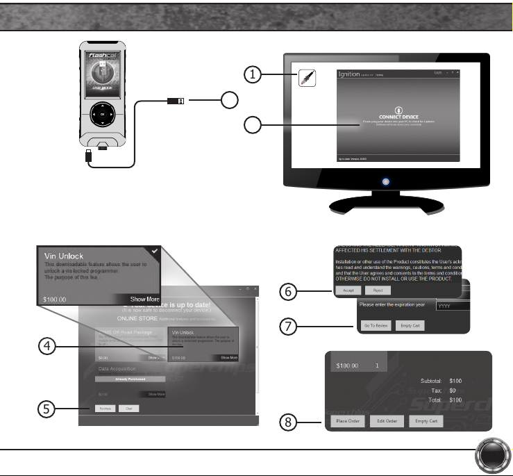
PRODUCT UPDATES USING IGNITION
1 Double-click the Ignition Icon located on your computer’s desktop.
2 Connect your device to the computer using the supplied USB cable.
(Ignition will automatically search for updates related to your device.)
3 Click the Update button.
(The update process will start and nish automatically. Once the update is
complete, you may be directed to the Online Store. To further update your
device using the online store, refer to the following steps.)
4 Click on any or all of the available options.
(A check mark will appear in the upper right corner.)
5 Click the Purchase button.
6 If required, read and Accept the disclaimer.
7 Fill in the required information and click Go to Review.
(Here you can check the information you lled in before submitting the order.)
8 Click the Place Order button to complete your order.
9 If a purchase was made, follow steps 1-3 above to complete the update.
8
Page 9
2
NOTICE
Do not unplug the USB while the device
is being updated. Once the update is
complete, you will be informed that it is
safe to disconnect.
4
1
Ignition
3
6
7
5
8
9
Page 10
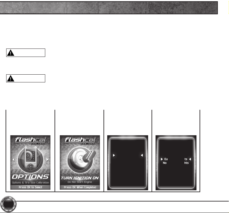
OPTIONS
These options allow to you quickly adjust the settings for the available
features.
NOTE: Not all features are available on every make, model, and engine.
CAUTION
Do not remove or bump the OBD-II connector while changing Quick option
settings. If you do, the vehicle may not start.
WARNING
Do not make adjustments to your vehicle while parked in unsafe locations
including heavy trafc or places without cell phone service.
STEP 1 - Enter
the Options Menu
by pressing ok.
10
STEP 2 - Follow
the on-screen
instructions.
STEP 3 - Select
an option from
the list provided.
Quick Options
Axle Lock
Engine Idle
Lamp Delay
Run Lights
Acc Delay
Lane Change
Lamp Flash
Horn Chirp
Fog Lights
Exit
STEP 4 - Modify
each setting
according to your
specic needs.
Daytime Run Lamps
High Beams
Low Beams
Turn Signals
Fog Lights
European Lights
No Running Lights
Page 11

OPTIONS EXPLAINED
Tire Size: This feature allows you modify the programmed Tire Height.
Axle Ratio: This feature allows you to adjust the calculated output shaft speed.
Engine Idle: This feature allows the user to increase the engine Idle RPM momentarily.
Run Lights: This feature allows you to change the Daytime Running lights conguration.
Engine Timing: This feature gives the option to Retard the Timing down a total of 6 degrees.
Tire Pressure: Adjust the tire pressure at which the TPMS warning light will illuminate for a low
tire-pressure condition.
Accessory Delay Adjustment: Adjust the length of time your radio stays on after key Off.
Automatic Door Lock Toggle: Allows you to turn ON or OFF the vehicle feature that
automatically locks your doors once the vehicle is in motion.
Horn Chirp: Allows you to turn ON or OFF the horn “chirp” when locking the vehicle.
Lamp Flash: Allows you to turn ON or OFF the vehicle lamp ash when locking the vehicle.
One Touch Lane Change: Allows you to toggle this vehicle feature ON or OFF. When this feature
is turned OFF, your blinker will only blink once after pressing the switch.
Transfer Case Ratio Adjustment: This feature allows you to adjust the ratio based on your Jeeps
specic transfer case.
Transfer Case HI Adjustment: Allows you to adjust the transfer case settings while in 4-HI.
Transfer Case LO Adjustment: Allows you to adjust the transfer case settings while in 4-LO.
11
Page 12
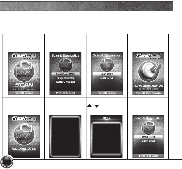
READ DTC
This feature allows you to troubleshoot issues that your vehicle may be experiencing. Most
vehicles will illuminate the in-dash check engine light. A Diagnostic Trouble Code (DTC) arises
when a vehicle’s computer detects a sensor failure or a parameter outside of specic range.
STEP 1 - Enter the
Scan Menu.
STEP 5 - Allow the
device to search for
DTCs.
12
STEP 2 - Select
Read/Clear DTCs.
STEP 6 - Read and
follow the on-screen
instructions.
Pressing UP or DOWN
will cycle through the
DTCs
Pressing OK or LEFT
will exit
Press OK to Continue
STEP 3 - Select
Read DTCs.
STEP 7 - Push the
/ arrows to
view each DTC.
DTC - 1of2
P0090
Fuel Pres Reg Ctrl Circ
STEP 4 - If asked,
turn ignition on,
but do not start.
STEP 8 - Press OK
to return to the
DTC menu.
Page 13
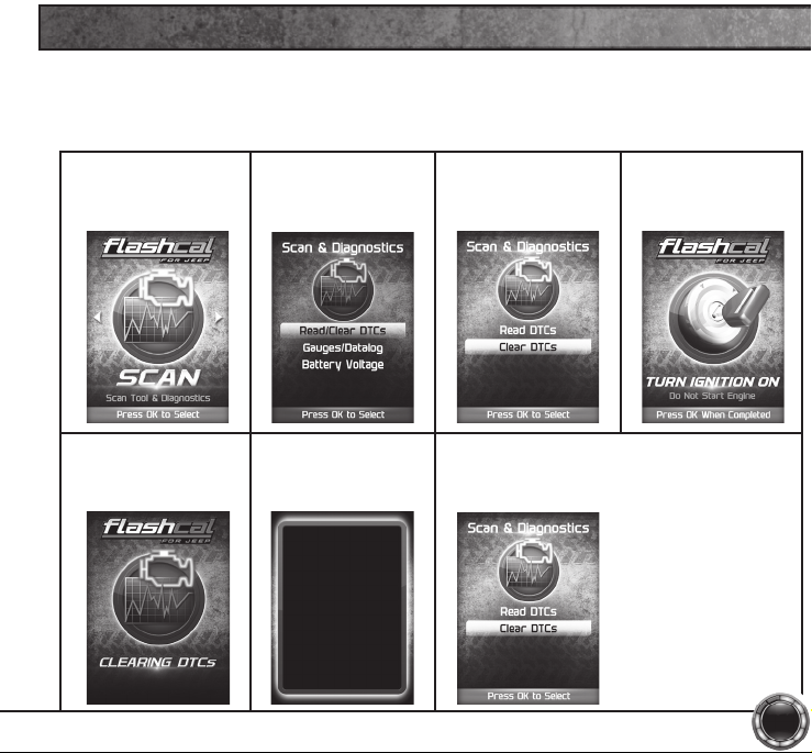
CLEAR DTC
This feature allows you to clear the DTC and turns off the check engine light.
NOTE: If a DTC persists, this could indicate a vehicle malfunction. We recommend seeking a
qualied professional in resolving the issue. Program the vehicle back to stock prior to service.
STEP 1 - Enter the
Scan Menu.
STEP 5 - Allow the
device to search for
DTCs to clear.
STEP 2 - Select
Read/Clear DTCs.
STEP 6 - Read and
follow the on-screen
instructions.
Vehicle DTCs
Successfully Cleared
Press OK to Continue
STEP 3 - Select
Clear DTCs.
STEP 4 - If asked,
turn ignition on,
but do not start.
STEP 8 - Press OK to return to the DTC
menu.
13
Page 14
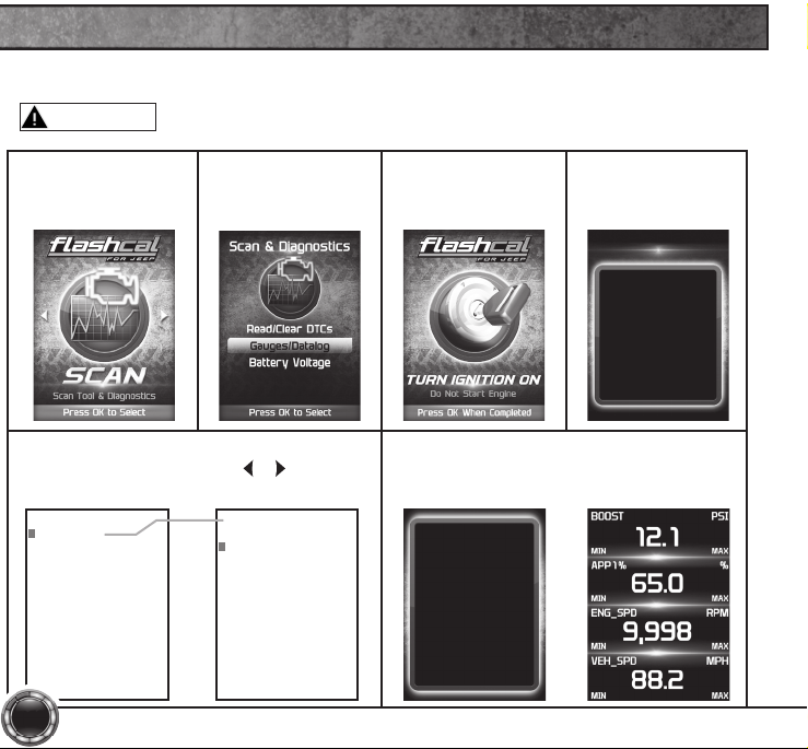
VIEWING GAUGES
If you would like to view Parameter IDs (PIDs) specic to your vehicle, following these
instructions to learn how to view them using your Flashcal device.
WARNING
Do not exceed legal speed limits on public roadways.
STEP 1 - Enter the
Scan Menu.
STEP 2 - Select
Gauges/Datalog.
STEP 5 - Select a PID Group, then select
a total of 4 PIDs. Use the / arrows to
switch between screens. OK to select.
PID Groups
Engine Misc
Fuel Trim/Press
Time/Distance
Oxygen Sensors
Misc Non-Engine
Egr/Evap
Catalyst Temp
Throttle Detail
Engine Misc
Calc Eng Load
Engine Coolant Temp
Manifold Abs Pressure
Engine RPM
Spark Advance
Intake Air Temperature
Mass Air Flow
Abs Throttle Position
14
STEP 3 - If asked,
turn ignition on,
but do not start.
STEP 4 - Follow
the on-screen
instructions.
GAUGES / DATALOG
Select 4 PIDs within the
following PID groups
Press OK to continue...
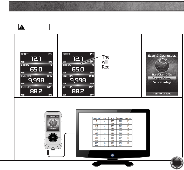
STEP 6 - Follow the on-screen
instructions. Note the RED highlights.
See DataLogging for more information.
While viewing gauges,
press OK to start
Datalogging
Press OK again to stop
Datalogging
Press OK to continue
Page 15
DATA LOGGING
Data logging allows you to record specic vehicle information while driving. Follow these
instructions to nd out how to datalog, and how it may be helpful to your particular needs.
WARNING
Do not exceed legal speed limits on public roadways.
STEP 1 - Refer to
the previous section
and follow the steps.
The information will be stored on the device and may be retrieved using a
computer. For more information continue to the next section.
STEP 2 - Press the OK button to begin
recording the PID data. Press the OK
button again, to stop the recording.
The separator lines
will change from
Red to Green,
which indicates
that the device is
actively recording
(datalogging).
STEP 3 - Press the
left arrow to return
to the menu.
15
Page 16
DATA LOGGING RETRIEVAL
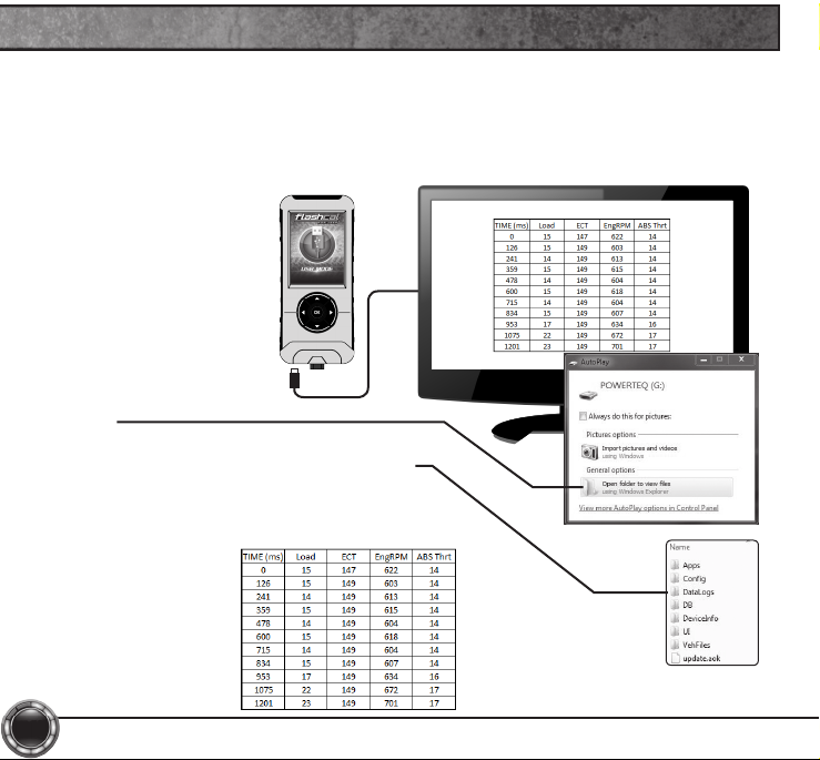
To learn more about how Data Logging results can be extracted from the device,
please follow these instructions:
STEP 1 - Remove the device from the vehicle OBDII port.
STEP 2 - Using the USB
cable provided, connect the
device to your computer.
STEP 3 - The device will
enter USB Mode, and allow
your computer to open it’s
les.
STEP 4 - Open the folder to
view les.
STEP 5 - Open the folder named DataLogs.
STEP 6 - Copy the Excel le to your computer
desktop, then open it. A le will open that looks
similar to the following:
16
Page 17
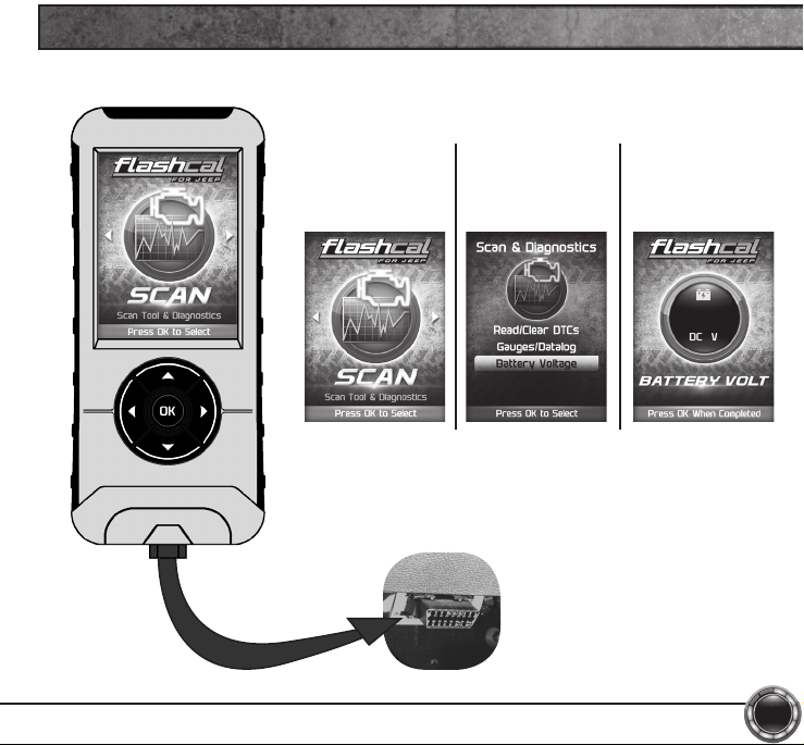
STEP 1 - Plug the device into the OBDII port.
BATTERY VOLTAGE
STEP 2 - Enter
the Scan Menu.
STEP 3 - Select
the Battery
Voltage option.
STEP 4 - Press
OK to return
to the previous
screen.
13.21
17
Page 18
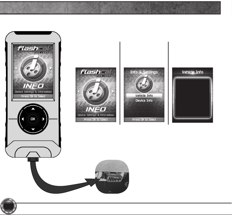
VEHICLE INFO
STEP 1 - Plug the device into the OBDII port.
18
STEP 2 - Enter
the Info Menu.
STEP 3 - Select
the ID Vehicle
option.
STEP 4 - Press
OK to return
to the previous
screen.
TUNING LEVEL
Stock
VIN
#################
Vehicle Files
########
Page 19
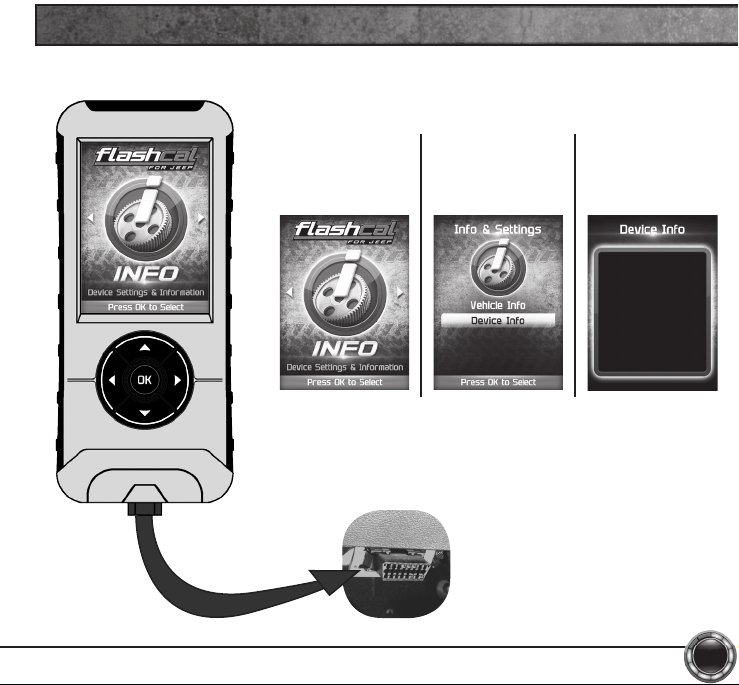
STEP 1 - Plug the device into the OBDII port.
DEVICE INFO
STEP 2 - Enter
the Info Menu.
STEP 3 - Select
the Device Info
option.
STEP 4 - Press
OK to return
to the previous
screen.
SKU:#########
APP: XX_XX_XX
APP Ver: 2
IAP Ver: 1
VID Ver: 1
DB Ver: 2085
SN: #########
Status: Stock
19
Page 20
SAFETY WARNING & CAUTION
Throughout this User Manual you will see important messages regarding your safety or
the protection of your vehicle. These messages are designated by the words WARNING,
CAUTION, or NOTICE.
WARNING
A WARNING indicates a hazardous situation which, if not avoided, will result in death or
serious injury.
CAUTION
A CAUTION indicates a hazardous situation which, if not avoided, could result in minor or
moderate injury.
NOTICE
A NOTICE indicates a condition that could cause damage to the product or your vehicle.
The Superchips product you have purchased is a high-performance product. As such, it does
present some risks of which you should be fully aware. Do not use this product until you have
carefully read the following safety information and the Owner Agreement.
NOTE: After the display has been installed, a warning screen will appear (3) different
times.
use to break legal speed limits. Before installing, read and comply with all information
If you agree with the agreement, select Yes to continue.
WARNING: Misuse of this device could lead to a serious accident. Do not
in the User Guide. Do you agree?
20
Page 21
SAFETY GUIDELINES
WARNING
Before using device, read and understand the user manual, including these additional
safety instructions. Failure to do so could result in DEATH or SERIOUS INJURY.
• Do not exceed legal speed limits on public roadways. Violating trafc laws is dangerous
and could result in injury or vehicle damage or both.
• Use any enhanced speed capabilities of this product only in closed circuit, legally
sanctioned racing environments expressly for this purpose. Violating trafc laws is
dangerous and could result in injury or vehicle damage or both.
• Do not operate the device while driving. Distracted driving could result in trafc accidents,
death or serious injury, and/or damage to your vehicle. Always perform all adjustments or
changes while stopped. Changing a setting while driving can interfere with your attention
to roadway conditions and could result in injury or vehicle damage or both.
• Do not stack products. “Stacking” performance-enhancing devices or other improper
installation can cause power train failure on the road. Other products may have
features incompatible with your Superchips device. Follow all installation and operating
instructions.
• Some modications may affect other parts of your vehicle. For example, if you remove/
adjust the speed limiter in your vehicle, be sure your tires and other components are
rated for the increased speeds they will have to withstand. Not doing so can lead to
loss of vehicle control. Modify the speed limiter only for use in closed circuit, legally
sanctioned racing environments, not for use on public roadways.
21
Page 22
LIMITED 1 YEAR WARRANTY
Powerteq, LLC, (hereafter “SELLER”), subject to the conditions and limitations set
forth herein, warrants to the original consumer purchaser only that each Flashcal
product sold by SELLER (the “Product”) through an authorized dealer will be free
from defects in material and workmanship under normal operating conditions for
one (1) year after the date of purchase. SELLER will repair or replace, at SELLER’s
option, any Product that is found to be defective in material or workmanship under
normal operating conditions during the one-year period after the date of purchase by
the original consumer purchaser.
What Is Not Covered by This Warranty?
This warranty does not apply to any of the following:
1. Loss, damage, repairs, or maintenance required as a result of accident, abuse,
negligence, or misuse.
2. Loss, damage, repairs, or maintenance required as a result of any third-party
tuning software.
3. Loss, damage, repairs, or maintenance required as a result of re, water, hail,
theft, earthquake, wind, ice, lightening, acts of god, accident, animals, corrosive
atmosphere, or other external causes beyond the control of SELLER.
4. Any special, indirect, incidental, consequential, or punitive damages, including
property damage, arising out of or related to the use or loss of use of the Product
under this Limited Warranty.
5. Any Products purchased through auction websites.
22
Page 23

Limitation of Liability
The terms of this Limited Warranty constitute the entire agreement between the parties
with respect to the Product. The original consumer purchaser’s exclusive remedy shall
be limited to the repair or replacement of the defective product.
EXCLUDING THE LIMITED WARRANTY PROVIDED ABOVE, SELLER, TO
THE MAXIMUM EXTENT PERMITTED BY LAW, MAKES NO WARRANTIES,
EXPRESSED OR IMPLIED, AND DISCLAIMS ALL WARRANTIES, DUEITES AND
CONDITIONS, WHETHER EXPRESS, IMPLIED, OR STATUTORY, WITH RESPECT
TO THE WORK, INCLUDING WITHOUT LIMITATION ANY IMPLIED WARRANTIES
OF MERCHANTABILITY OR FITNESS FOR A PARTICULAR PURPOSE. ANY
REMEDY IS LIMITED TO THE PURCHASE PRICE OF THE PRODUCT.
How to Make a Warranty Claim
Contact Powerteq Customer Service. BUYER will be required to submit proof of
purchase from an authorized dealer within 5 days of the warranty claim.
THE INSTALLATION OF THIS PRODUCT INDICATES THAT THE BUYER HAS
READ AND UNDERSTANDS THIS AGREEMENT AND ACCEPTS ITS TERMS AND
CONDITIONS. IN THE EVENT THAT THE BUYER DOES NOT AGREE WITH THIS
AGREEMENT, THE BUYER MAY PROMPTLY RETURN THIS PRODUCT, IN A NEW
AND UNUSED CONDITION, WITH A DATED PROOF OF PURCHASE, TO THE
PLACE OF PURCHASE WITHIN THIRTY (30) DAYS FROM DATE OF PURCHASE
FOR A FULL REFUND.
23
Page 24

WWW. .COM
1790 East Airport Blvd. | Sanford, FL 32773 | Ph: 407.585.7000
 Loading...