

Manual
LITHIUM BATTERY
SB12V160E-ZC
12.9V/160Ah
Lithium Iron Phosphate
Version
June 2018

2
User Manual SB12V160E-ZC Lithium Iron Phosphate
battery
Dear customer,
This is your lightweight Super B SB12V160E-ZC traction Li-ion battery. A high performance
Li-ion battery with only 1/3 of the size of a conventional lead acid battery. The Li-ion battery is
designed to replace the much heavier 250 to 320 Ah lead-acid battery.
This manual contains all the information necessary to install, use and maintain the Li-ion
battery. We kindly ask you to read this manual carefully before using the product. In this
manual, the Super B SB12V160E-ZC Li-ion battery will be referred to as: the Li-ion battery.
This manual is meant for the installer and the user of the Li-ion battery. Only qualified,
certified personnel may install and perform maintenance on the Li-ion battery. Please consult
the index at the start of this manual to locate information relevant to you.
The boundaries of its use, as described in this manual should always be upheld. The Li-ion
battery may not be used in medical or in aviation related applications. The Li-ion battery may
not be used for any purposes other than described in this manual. Using the Li-ion battery for
any other purpose will be considered improper use and will void the warranty of the product.
Super B cannot be held responsible for any damage caused by improper, incorrect or unwise
use of the product. Read and understand this manual completely before using the product.
During the use of the product, user safety should always be ensured, so installers, users,
service personnel and third parties can safely use the Li-ion battery. This is the original
manual, keep it in a safe location! Please consult www.super-b.com for the latest version of
all manuals.
Copyright© Super B All rights reserved. Licensed software products are owned by Super B
or its subsidiaries or suppliers, and are protected by national copyright laws and international
treaty provisions. Super B products are covered by Dutch and foreign patents, issued and
pending. Information in this publication supersedes that in all previously published material.
Specifications and price change privileges reserved. Super B is a registered trademark of
Super B

3
Be in charge Super B
For more information, or to order documents, contact:
Super B
Expolaan 50
7556 BE Hengelo (Ov) The Netherlands
Tel: +31(0)748200010
E-mail: support@super-b.com
www: www.super-b.com
The Netherlands
Tel: +31(0)748200014 (support)
E-mail: support@super-b.com
www: www.super-b.com
Be in charge Super B

4
Table of content
1. Introduction 6
1.1. Product description 6
1.2. Glossary of Terminology 6
1.3. Used symbols 6
2. Product specifications 7
2.1. Product features 7
2.2. General product specifications 7
2.3. Technical specifications 7
2.3.1. Battery designation 8
2.3.2. Electrical properties (23°C) 8
2.3.3. Dimensions (±1mm) 8
2.4. Environmental conditions 9
2.4.1. Marine use 10
2.5. Required tools 10
2.6. Components 11
2.6.1. List of components 11
2.7. Connections, indicators and battery controls 11
2.7.1. Con1 (Output for BI-Stable Relay) 12
2.7.2. Con2 (I/O connection 7) 12
2.7.3. Con 3 (CANopen; 5-pin “micro” style connector) 13
2.8. Peripheral equipment 13
2.8.1. Obligatory 13
2.8.2. Optional Components 14
3. Safety guidelines and measures 15
3.1. General 15
3.2. Disposal 15
3.3. Safety symbols and markings on product 16
4. Installation 17
4.1. General information 17
4.2. Unpacking 17
4.3. Preparing the battery for use 17
4.3.1. Placement of the battery 17
4.3.2. Placement and removal of a fuse 18
4.4. Connection wires 19
4.5. Installing the mandatory Battery Disconnect device 19
4.5.1. Connecting a bi-stable relay to the Li-ion battery 19
4.5.2. Connecting a normal relay as Battery Disconnect device 20
4.5.3. Using the SB BIB (Battery Interface Box)
21

5
Be in charge Super B
4.5.4. Using the SB BCI-C1 (Battery Communication Interface) with a normal relay 21
4.6. Connecting the Li-ion battery to the load/charger 22
4.6.1. Connecting a single Li-ion battery to the load/charger with a bi-stable relay 22
4.6.2. Connecting a single Li-ion battery to the load/charger with a normal relay 23
4.6.3. Connecting Li-ion batteries in series. 25
4.6.4. Connecting Li-ion batteries in parallel 25
4.6.5. Connecting Li-ion batteries in series and parallel 26
4.7. CANopen interface 27
4.7.1. CAN Bus network topology 28
4.7.2. Termination Resistors 28
4.7.3. CAN balancing 29
5. Battery use 30
5.1. General information 30
5.2. Charging 30
5.2.1. Charging rate 30
5.2.2. Charging method 31
5.2.3. Battery balancing 33
5.2.4. Reading out the battery’s State of Charge (SoC) 33
5.3. Battery Monitoring Software 34
5.3.1. Battery History Recording 34
6. Inspection, cleaning and maintenance 35
6.1. General information 35
6.2. Inspection 35
6.3. Cleaning 35
7. Storage 36
8. Transportation 36
8.1. General 36
9. Disposal and recycling 37
9.1. General information 37
10. Troubleshooting 38
11. Warranty and liability 39
Appendix I. Declaration of Conformity 41
Appendix II. Performance Graphs 42
Appendix III. Conductor requirements 43
6
1. Introduction
1.1. Product description
The SB12V160E-ZC is a Lithium Iron Phosphate rechargeable battery. The unique combination
of state-of-the art technology and smart software makes this Li-ion battery a robust, safe and
easy to use energy storage solution.
Compared to conventional lead acid batteries, the Li-ion battery offers an enormous weight
and space saving. It is very efficient, has extremely high performance and is maintenance
free.
Moreover, the Li-ion battery uses exceptionally safe Lithium Iron phosphate (LiFePO4)
technology. With its integrated battery management system the Li-ion battery is protected
from deep discharging, overcharging and overheating.
External disconnect device is required!
Potential applications of this Li-ion battery include: off grid power supply, marine power
supply, medium for (renewable) energy storage (traction) battery for vehicles.
In Appendix I, the Declaration of Conformity for the Li-ion battery is given.
1.2. Glossary of Terminology
BMS Battery Managent System
Charge cycle
A period of use from fully charged, to fully discharged, and fully recharged
again.
Endurance Life-cycle
The products maximum lifespan, achieved by following the guidelines
presented in this manual.
BCI Battery Communication Interface
LiFeP04 Lithium Iron Phosphate
SoC State of charge
CCCV Constant Current - Constant Voltage
DoD Depth of Discharge
Table 1. Glossary of terminology
1.3. Used symbols
The following icons will be used throughout the manual:
!
Warning! A warning indicates severe damage to the user and/or product may occur when a
procedure is not carried out as described.
7
Be in charge Super B
!
Caution! A caution sign indicates problems may occur if a procedure is not carried out as
described. It may also serve as a reminder to the user.
2. Product specifications
2.1. Product features
• Traction battery
• Lithium Iron Phosphate (LiFePO4): Safe Li-ion technology
• Integrated BMS (Battery Management System), external interruption device needed
• Glass fiber reinforced plastic (GRFP) Casing, Aluminum / PE sandwich side panels
• Terminals for 2 x 95mm2 wire connection per terminal
• Integrated fuse, 72V / 500A
• 3C continuous discharge (480A)
• Wired communication infteraface: CANopen
• Battery monitoring / History Storage
• Adaptive cell balancing
• Configurable in serial or parallel connection
• Output for bi-stable relay / latching relay
2.2. General product specifications
Product name SB12V160E-ZC
Producer Super B
Battery type Lithium Iron Phosphate (LiFePO4) / Traction battery
EAN number 8718531360570
Cycle life > 2000 (0.3C continuous discharge, DoD 100%)*
Table 2. General product specifications
*The cycle life value given above is an indication at 23°C. The Li-ion battery cycle life
depends strongly on temperature and the applied charging and discharging loads. For more
information on the cycle life of the Li-ion battery, appendix II may be consulted.
2.3. Technical specifications
Mass 26.9 kg +/- 0.250 kg
Ingress protection rating IP50
Table 3. Technical specifications
8
2.3.1. Battery designation
Battery designation according to
EC61960
4IFpP85/170/245
Table 4. Battery
2.3.2. Electrical properties (23°C)
Open Circuit Voltage* 13.2V dc
Nominal voltage** 12.9V dc
Rated capacity 160Ah
Charge method CCCV
Charge voltage 14.3V...14.6V
End-of-discharge voltage 8V dc
Charge current Max 160A (1C)
Discharge current continuous 480A (3C)
Discharge current 10 seconds 800A (5C)
Table 5. Electrical properties (23 °C)
*Open Circuit Voltage at 50% SoC, no load
**Nominal voltage (V) at 50%, SoC, 0.2C discharge
More information on the Li-ion battery’s discharge performance and capacity may be found in
Appendix II.
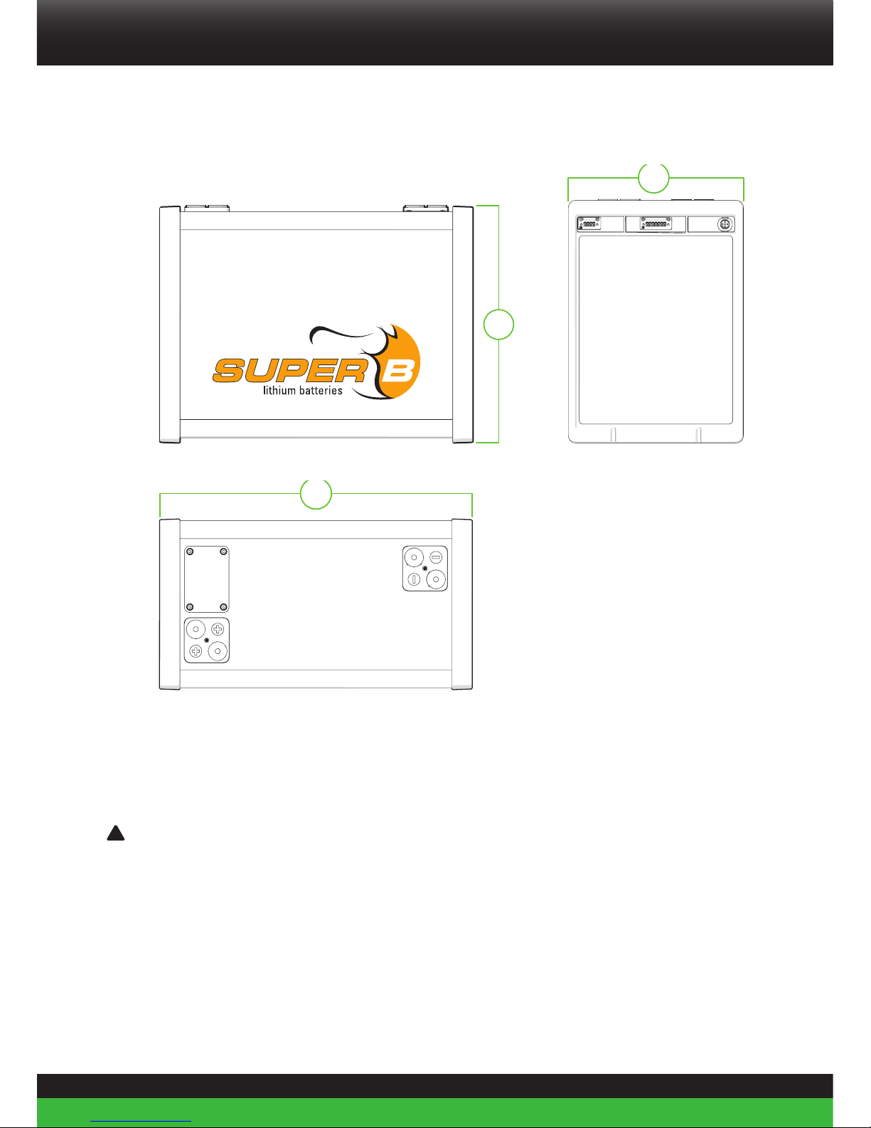
2.3.3. Dimensions (±1mm)
Height (H) 314 mm
Width (W) 417 mm
Thickness (T) 227 mm
Table 6. Dimensions
9
Be in charge Super B
313.0
314.0
225.0
226.0
413.5
414.5
Figure 1. Dimensions
2.4. Environmental conditions
!
Warning! The Li-ion battery may only be used in conditions specified in this manual. Exposing
the Li-ion battery to conditions outside the specified boundaries may lead to serious damage
to the product and/or the user.
Use the Li-ion battery in a dry, clean, dust free, well ventilated space. Do not expose the Liion battery to fire or water or solvents.
When the Li-ion battery is placed in an enclosed environment without air circulation, it is
advised to provide 2 ventilation holes of 100mm x 100mm each. This helps to prevent the heat
built-up.
10
Recommended charge temperature range* 0°C to +45°C
Discharging operating temperature range -10°C to +55°C
Short term (<1 month) storage temperature range -20°C to +45°C
Long term (>1 month) storage temperature range -10°C to +20°C
Relative humidity 10-90%
Corrosion Salt-contaminated atmosphere up to
1 mg salt per m3 of air, at all relevant
temperatures and humidity conditions.
Applicable to equipment located in open air
and made of material subject to corrosion.
Placement angle (continuously) Up right
Vibrations and shocks According UN38.3
Table 7. Environmental conditions
(1) Charging below 0 °C only with reduced charge current. This might result in degraded cycle life.
2.4.1. Marine use
Parameter Class Location
Temperature A Machinery spaces, control rooms, accommodation, bridge
Humidity B All locations except as specified for location A
Vibration A On bulkheads, beams, deck, bridge
EMC B All locations including bridge and open deck
Table 8. Marine use
2.5. Required tools
• 13mm Hexagon socket wrench
• Torque wrench
• TORX key for fuse cover
11
Be in charge Super B
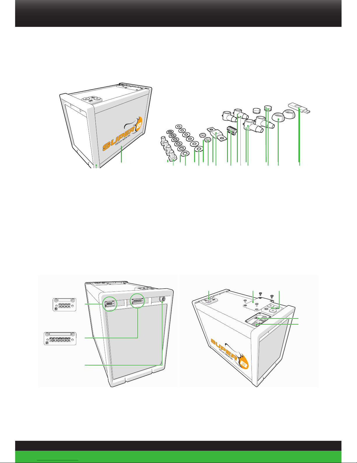
2.6. Components
Figure 2. Components
2.6.1. List of components
1. (1) Super B SB12V160E-ZC Battery
2. (4x) M8 Bolt
3. (6x) M8 Spring washer
4. (6x) M8 Plain washer
5. (2x) M8 Nut
6. (1x) Mega Fuse 72V/500A
7. (1x) Phoenix plug 7
8. (2x) Terminal cover, Red
9. (2x) Terminal cover, Black
10. (1x) Terminal protection cap, Red
11. (1x) Terminal protection cap, Black
12. (1x) USB stick (manual)
2.7. Connections, indicators and battery controls
1 2 3 4 5 6 7
1 2 3 4
1
2
3
64 5
7
8
Figure 3. Connections, indicators and battery controls
32 4 5 6 8 10 11 12971
12
1. Con 1 (Output for BI-Stable Relay; Phoenix FRONT-MC 1,5/4-STF-3,81 1850877)
2. Con 2 (I/O Connection 7; Phoenix FRONT-MC 1,5/7-STF-3,81 1850903)
3. Con 3 (CANopen; 5-pin “micro” style connector)
4. Terminal - (2x 95mm2 wire connection)
5. Fuse cover
6. Terminal + (2x 95mm2 wire connection)
7. Reset button
8. Fuse connections
2.7.1. Con1 (Output for BI-Stable Relay)
PIN # Output range (12V dc) Function
1
2.7A (continuous)
15A (100ms pulse)
+, OFF
2
2.7A (continuous)
15A (100ms pulse)
-, ON
3
2.7A (continuous)
15A (100ms pulse)
-, OFF
4
2.7A (continuous)
15A (100ms pulse)
+, ON
Table 9. Con1 (Output for BI-Stable Relay) Output Functions
2.7.2. Con2 (I/O connection 7)
PIN # Range Function
1 max 30 V dc + (Plus)
2 0-10 V dc AN_SOC (Analogue state of charge)
3 NA Nc (Not connected)
4
5A max
48V dc max
Rc, (Relay common contact)
5 Rnc, (Relay normaly close contact)
6 Rno, (Relay normaly open contact)
7 GND, (Ground)
Table 10. (I/O connection 7)

13
Be in charge Super B
2.7.3. Con 3 (CANopen; 5-pin “micro” style connector)
PIN # Signal Description
1 CAN_SHLD Optional CAN Shield
2 CAN_V+
Optional CAN external positive supply
(dedicated for supply of transceiver and
optocouplers. if galvanic isolation of the bus
node applies)
3 CAN_GND Ground / 0V
4 CAN_H CAN_H bus line (dominant high)
5 CAN_L CAN_L bus line ( dominant low)
Table 11. Con 3 (CANopen; 5-pin “micro” style connector)
2.8. Peripheral equipment
2.8.1. Obligatory
In order for the Li-ion battery to be used safely, an external switch off device must be
installed. This should either be a relay or latching relay (bi-stable) controlled by the battery’s
BMS or a relay or latching relay controlled by a remote switch (CAN controlled). If an
external switch off device is not installed the warranty of the Li-ion battery will be void.
14
2.8.2. Optional Components
The Li-ion battery can be used in combination with a number of (Super B) products:
Description Article name EAN code
SB-LIR250 (relay) SB-LIR250 (relay) 8718531361126
BI-Stable relay SB-V23130C2021A412-TE (latching relay) 8718531361010
Terminator Resistor Female SB CAN Terminator Resistor Female 8718531360808
Terminator Resistor Male SB CAN Terminator Resistor Male 8718531360815
CAN Male-female Cable 0.6m SB CAN Male-female Cable 0.6m 8718531360716
CAN Male-female Cable 1m SB CAN Male-female Cable 1m 8718531360723
CAN Male-female Cable 2m SB CAN Male-female Cable 2m 8718531360730
CAN Male-female Cable 5m SB CAN Male-female Cable 5m 8718531360747
CAN Male-female Cable 10m SB CAN Male-female Cable 10m 8718531360754
T-splitter SB CAN T-splitter 8718531360761
Battery Interface Box SB BiB LV48V350A 8718531360914
USB to CAN CAN Compact to USB 8718531361201
Battery monitor SB Monitor Software
Mounting bracket ZC casing
SB Battery Bracket for SB12V100E-ZC and
SB12V160E-ZC
8718531360693
Battery Communication
Interface
SB BCI-C1 8718531360884
Touch Display Touch Display 8718531361447
Touch Display + Cable Touch Display + Cable 8718531361447
BM01 Battery monitor SB BM01 12-24V 8718531361041
BM01 Battery monitor cable SB BM 01 Cable 2.5m 12-24V only 8718531361225
BM01 Battery monitor cable SB BM 01 Cable 5m 12-24V only 8718531361232
BM01 Battery monitor cable SB BM01 Cable 10m 12-24V only 8718531361249
Table 12. Optional components that can be used with the Li-ion battery

15
Be in charge Super B
3. Safety guidelines and measures
3.1. General
• Do not short-circuit the Li-ion battery.
• Treat the Li-ion battery as described in this manual.
• Do not dismantle, crush, puncture, open or shred the Li-ion battery.
• Do not expose Li-ion battery to heat or fire. Avoid exporusre to direct sunlight.
• Do not remove the Li-ion battery from its original packaging until required for use.
• In the event of the Li-ion battery leaking, do not allow the liquid to come in contact with the
skin or eyes. If contact has been made, wash the affected area with copious amounts of
water and seek medical advice.
• Do not use any charger other than that specifically provided for use with the Li-ion battery.
• Observe the plus (+) and minus (–) marks on the Li-ion battery and equipment and ensure
correct use.
• Do not use any battery which is not designed for use with the Li-ion battery.
• Do not mix batteries of different manufacture, capacity, size or type within a device.
• Keep the Li-ion battery clean and dry.
• Secondary batteries need to be charged before use. Always use the correct charger and
refer this manual for proper charging instructions.
• Do not leave the Li-ion battery on prolonged charge when not in use.
• After extended periods of storage, it may be necessary to charge and discharge the Li-ion
battery several times to obtain maximum performance.
• Retain the original product documentation for future reference.
• Remove the Li-ion battery from the equipment when not in use.
!
Warning! Keep the Li-ion battery away from water, dust and contamination.
3.2. Disposal
Dispose of the Li-ion battery in accordance with local, state and federal laws and
regulations.
Batteries may be returned to the manufacturer.
Do not mix with other (industrial) waste.

16
3.3. Safety symbols and markings on product
Several safety symbols and markings can be found on the product. These markings are
displayed below. Never remove these markings!
The meanings of the symbols:
Shield eyes
Note operating instructions
Battery acid
Explosive gas
No smoking, no naked flames, no sparks
Keep away from children
Dispose of the Li-ion battery in accordance with local, state and federal laws and
regulations. Batteries may be returned to the manufacturer. Do not mix with other
(industrial waste)
This product, or sections of this product can be recycled
Table 13. Safety symbols

17
Be in charge Super B
4. Installation
4.1. General information
!
Warning! Never install or use a damaged Li-ion battery.
!
Caution! Do not reverse connect the Li-ion battery(polarity)
When connecting several batteries in series or parallel, always use batteries of the same
brand, type, age, capacity and state of charge.
4.2. Unpacking
Check the Li-ion battery for damage after unpacking. If the Li-ion battery is damaged, contact
your reseller or Super B. Do not install or use the Li-ion battery if it is damaged!
4.3. Preparing the battery for use
!
Caution! Do not operate the Li-ion battery beyond published maximum specifications.
!
Caution! In case of an under-voltage shutdown, charge immediately.
!
Warning! Always remain within the limits indicated in chapter 2 during the use of the
Li-ion battery.
!
Caution! This Li-ion battery stores fault conditions internally, like excessive charge current or
deep discharge situations. Super B uses this information in the warranty process
!
Warning! Do not overcharge the Li-ion battery.
4.3.1. Placement of the battery
Before it is used, the Li-ion battery must be positioned in such a way that it will not move
around in its compartment during use. If necessary, the Li-ion battery may be fixed in place
by means of Super B mounting brackets. The brackets can be screwed in place by means of
bolts or screws (See Figure 4).

18
Figure 4. Installing the Li-ion battery using the Super B mounting brackets
4.3.2. Placement and removal of a fuse
Before the Li-ion battery can be used, the internal fuse needs to be installed into it. The 72V/500A
fuse is supplied with the Li-ion battery. Other fuses may only be used in the product when they
are approved by Super B for this application.
Use the following steps to (re)place the fuse in the Li-ion battery (Figure 5):
1. Disconnect the negative wire from the - pole of the Li-ion battery (see paragraph 4.5.5. for the details).
2. Disconnect the positive wire from the + pole of the Li-ion battery.
3. Unscrew the fuse cover using the fuse TORX key.
4. Unscrew the fuse contacts using a 13mm wrench.
5. Place the (new) fuse between the contacts, place washers and spring washers and tighten the fuse
contact points to 20Nm.
6. Fasten the fuse cover.
7. Proceed to the next paragraph to read the instructions on installing the Li-ion battery in an electrical
circuit.

19
Be in charge Super B
Figure 5. Install a fuse
4.4. Connection wires
Use appropriate wire for the connection wires to ensure no overheating or unnecessary
losses occur. Use appropriate fuses matching the wires and load. See appendix III for more
details.
4.5. Installing the mandatory Battery Disconnect device
!
Warning! Always connect the relay between the + or - terminal of the battery and the load.
!
Warning! Never use the Li-ion battery without a properly installed Battery Disconnect device (relay
or latching relay).
An external Battery Disconnect device must be installed between the + or - terminal of the
Li-ion battery and the load. The protection of the Li-ion battery is possible by one of the
following ways:
1. Connect a bi-stable relay to the Li-ion battery’s Con1 output.
2. Connect a normal relay to the Li-ion battery’s Con2 (I/O connection 7) output.
3. By using the SB BIB (Battery Interface Box).
4. By using the SB BCI-C1 (Battery Communication Interface) and a normal relay.
4.5.1. Connecting a bi-stable relay to the Li-ion battery
1. When using a bi-stable relay connect it to Con1 output as displayed in Figure 6.
The Con1 output controls both the ON coil and the OFF coil of the bi-stable relay. The output
of Con1 can be found in Table 9.

20
Load/Charger
Bi-stable Relay
Figure 6. Connect a bi-stable relay as Battery Disconnect device
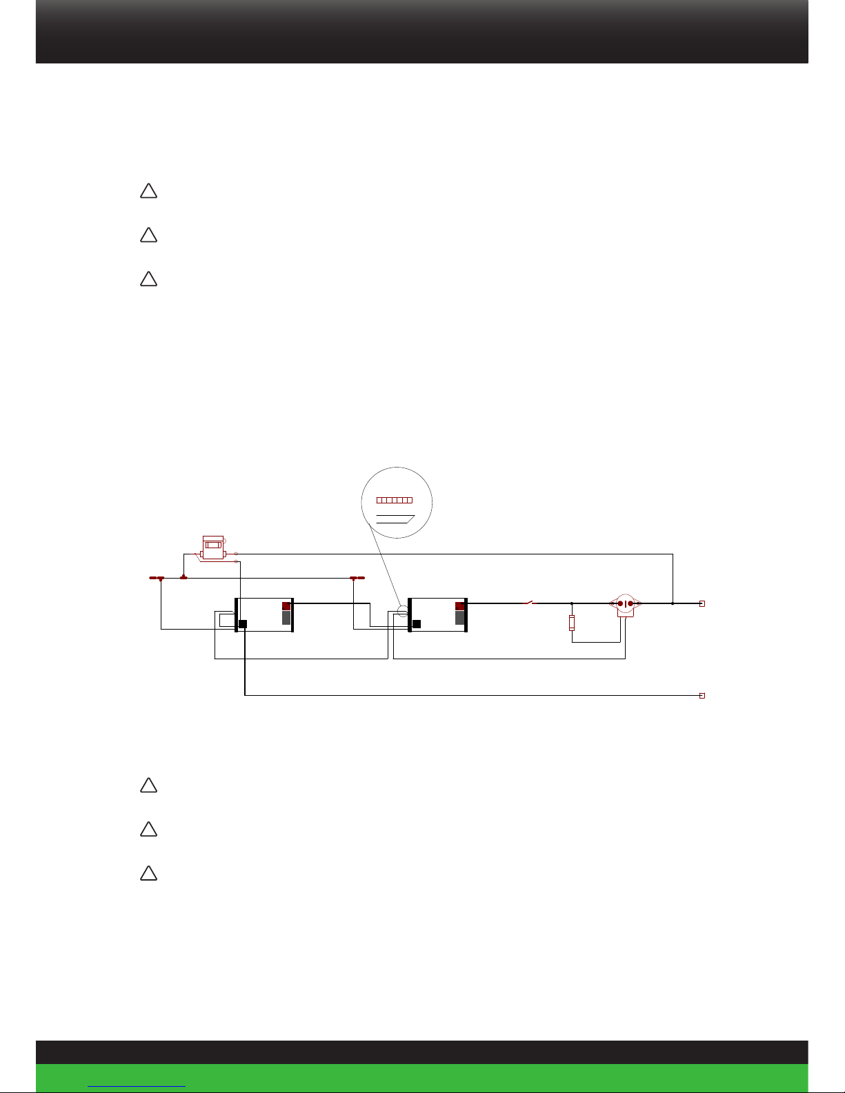
4.5.2. Connecting a normal relay as Battery Disconnect device
1. When using a normal relay, connect it to Con 2 (I/O Connec tion 7), Pin 4 (Rc) and Pin 5 (Rnc)
as displayed in Figure 7.
Normal relay
Load/Charger
Figure 7. Connect a normal relay as Battery Disconnect device.

21
Be in charge Super B
4.5.3. Using the SB BIB (Battery Interface Box)
Figure 8. Connecting a Li-ion battery to the SB BIB
Consult the manual of the SB BIB for installation instructions.
4.5.4. Using the SB BCI-C1 (Battery Communication Interface) with a normal relay
CAN_Term_FemaleCAN_Term_Male
J2_IO
J3_CAN
J1_BREL
J2_IO
J3_CAN
J1_BREL
3
4
5
6
7
8 9
A
B
C
FUSE
S1
S2
FUSE
J1 J2
J3 J4
S3
X1
X2
BT11
X1
X2
BT12
X1(+) X2(-)
K2
22Ω 50W
Minus (-)
Plus (+)
Manual Control
5A
5A
BCI
1. RECOVER RELAY COM
2. RECOVER RELAY NO
3. RESET IN +
4. RESET IN -
5. PRECHARGE IN +
6. PRECHARGE IN -
7. OFF IN +
8. OFF IN -
9. ON IN +
10. ON IN -
10. LOAD +
9. BATTERY +
8. MAIN RELAY HIGH SIDE COM
7. MAIN RELAY HIGH SIDE NO
6. MAIN RELAY LOW SIDE COM
5. MAIN RELAY LOW SIDE NO
4. PRECHARGE RELAY COM
3. PRECHARGE RELAY NO
2. IO1
1. GND
CAN MASTER CAN SLAVE
D1
ORANGE
D2
GREEN
D3
RED
+
+
_
_
Fuse
+
+
_
_
Fuse
A2 A1
Figure 9. Connecting a Li-ion battery to the SB BCI-C1
Consult the manual of the SB BCI-C1 for installation instructions.

22
4.6. Connecting the Li-ion battery to the load/charger
4.6.1. Connecting a single Li-ion battery to the load/charger with a bi-stable relay
!
Warning! Ensure you have completed all the previous steps described in chapter 4.5 before
connecting the battery to the load/charger.
1. Slide the terminal covers over the connection wires.
2. Connect the + terminal of the battery to the - or A terminal of the relay (Figure 10).
3. Connect the load or charger to the + or B terminal of the relay.
4. Connect the - terminal of the battery. Do not connect the - terminal first as this may lead to short
circuits (Figure 10).
5. Ensure both contacts are tightened to 20Nm.
6. Place the terminal covers over the terminals (Figure 11).
7. Press the reset button for 10-15 seconds after connecting the bi-stable relay to Con1 output.(the reset
button is located under the fuse cover). The bi-stable relay contacts will be turned off and on, this is to
make sure that the bi-stable relay is ON
Figure 10. Connecting the battery to the load
2
1
Bi-stable Relay
4
3
5
20 Nm

23
Be in charge Super B
Load/Charger
Bi-stable Relay
Figure 11. Securing the terminal covers
4.6.2. Connecting a single Li-ion battery to the load/charger with a normal relay
!
Warning! Ensure you have completed all the previous steps described in chapter 4.5 before
connecting the battery to the load/charger.
1. Slide the terminal covers over the connection wires.
2. Connect the + terminal of the battery to the - or A1 terminal of the relay (Figure 12).
3. Connect the load or charger to the + or A2 terminal of the relay.
4. Connect the - terminal of the battery. Do not connect the - terminal first as this may lead to short
circuits (Figure 12).
5. Ensure both contacts are tightened to 20Nm.
Place the terminal covers over the terminals (Figure 13)

24
2
1
Normal relay
4
3
5
20 Nm
Figure 12. Securing the terminal covers.
Normal relay
Load/Charger
Figure 13. Connecting the battery to the load
25
Be in charge Super B
4.6.3. Connecting Li-ion batteries in series.
!
Caution! Before connecting 2 or more Li-ion batteries, the Li-ion batteries must be
charged to 100% SoC.
!
Caution! For more than 4 Li-ion batteries in series connection consult Super B or your
dealer.
!
Caution! Depending on the installation a precharge circuit is needed. For further
information consult Super B or your dealer.
When using Li-ion batteries in series configuration CAN balancing is required (see
paragraph 4.7.4.).
The CAN power cable is necessary for CAN balancing.
In installations with more than 2 batteries in series the CAN power cable should be powered
from an external 24V power supply.
J2_IO
J3_CAN
J1_BREL
J2_IO
J3_CAN
J1_BREL
1 2
3
4
5
6
7
8 9
A
B
C
CAN_Term_Female
CAN_Term_Male
X1
X2
X1
X2
Plus
Minus
K1
Rc Rnc Rno
1 2 3
4 5 6 7
gndV+ soc nc
FUSE
FUSE
CAN
Red(+)
Black(-)
CAN Power Cable
Minus (-)
Plus (+)
Rc
RncRnc
Rc
RncRnc
Con J2 (IO connections)
Rc (pin 4)
Rnc (pin 5)
5A
Main Switch
+
+
_
_
Fuse
+
+
_
_
Fuse
A1 A2
Figure 14. Batteries connected in series with CAN power cable and disconnecting device
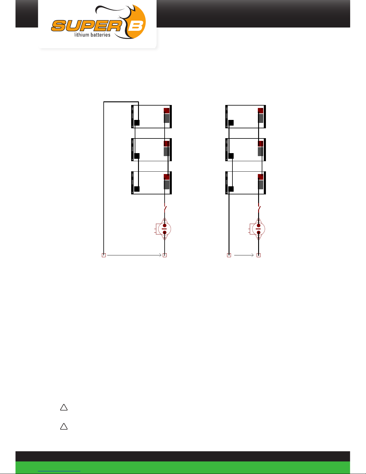
4.6.4. Connecting Li-ion batteries in parallel
!
Caution! Before connecting 2 or more Li-ion batteries, the Li-ion batteries must be
charged to 100% SoC.
!
Caution! For more than 4 Li-ion batteries in parallel connection consult Super B or your
dealer.
!
Caution! Depending on the installation a precharge circuit is needed. For further
information consult Super B or your dealer.
26
J2_IO
J3_CAN
J1_BREL
J2_IO
J3_CAN
J1_BREL
J2_IO
J3_CAN
J1_BREL
J2_IO
J3_CAN
J1_BREL
J2_IO
J3_CAN
J1_BREL
J2_IO
J3_CAN
J1_BREL
X1
X2
BT1
X1
X2
BT2
X1
X2
BT3
Plus
Minus
K3
X1
X2
BT4
X1
X2
BT5
X1
X2
BT6
Plus
Minus
K1
Minus (-)
Load
Plus (+)
Minus (-)
Load
Plus (+)
OK NOT OK
+
+
_
_
Fuse
+
+
_
_
Fuse
+
+
_
_
Fuse
A1 A2
+
+
_
_
Fuse
+
+
_
_
Fuse
+
+
_
_
Fuse
A1 A2
Figure 15. Three Li-ion batteries in parallel with external relay
OK: Equally divided battery current.
All batteries contribute equally to the current into the load.
NOT OK: Current not equally divided.
Batteries closest to load will have the highest contribution to the current into the load.
Whereas batteries further away from load will have lesser current contribution.
Wear and tear will be higher on the Li-ion battery close to the load.
When using Li-ion batteries in parallel configuration CAN balancing is not required.
4.6.5. Connecting Li-ion batteries in series and parallel
!
Caution! Before connecting 2 or more Li-ion batteries, the Li-ion batteries must be
charged to 100% SoC.
!
Caution! For more than 4 Li-ion batteries in series and parallel connection consult Super B
or your dealer.

27
Be in charge Super B
!
Caution! Depending on the installation a precharge circuit is needed. For further
information consult Super B or your dealer.
When using Li-ion batteries in series and parallel configuration CAN balancing is required
(see paragraph 4.7.4).
The CAN power cable is necessary for CAN balancing.
In installations with more than 2 batteries in series the CAN power cable should be powered
from an external 24V power supply.
J2_IO
J3_CAN
J1_BREL
J2_IO
J3_CAN
J1_BREL
J2_IO
J3_CAN
J1_BREL
J2_IO
J3_CAN
J1_BREL
1 2
3
4
5
6
7
8 9
A
B
C
CAN_Term_Female
CAN_Term_Male
FUSE
CAN
Red(+)
Black(-)
CAN Power Cable
X1
X2
X1
X2
X1
X2
X1
X2
Plus
Minus
K2
Rc Rnc Rno
1 2 3
4 5 6 7
gndV+ soc nc
FUSE
Minus (-)
Plus (+)
Rc
RncRnc
Rc
RncRnc
Rc
RncRnc
Rc
RncRnc
Con J2 (IO connections)
Rc (pin 4)
Rnc (pin 5)
5A
Main Switch
+
+
_
_
Fuse
+
+
_
_
Fuse
+
+
_
_
Fuse
+
+
_
_
Fuse
A1 A2
Figure 16. Four Li-ion batteries in a series - parallel connection with external relay
4.7. CANopen interface
The CANopen interface of the Li-ion battery must be used for CAN balancing and can be used
for monitoring purposes.
The Li-ion battery can be monitored using the Battery Monitor software and the Touch
Display Screen.
(see paragraph 2.8.2)
To use the Battery Monitoring Software, the CAN bus of the Li-ion battery (CON 3) needs to
be connected by means of CAN-to-USB interface to the computer on which the monitoring
software and the usb drivers are installed.
More information about the CANopen bus can be found at the CiA website: www.can-cia.org.

28
4.7.1. CAN Bus network topology
The CAN Bus must be used in a bus network topology. Do not use a ring- or a star topology.
The maximum CAN bus legnth is limitted because the Li-ion battery has a fixed bitrate of
250kbps.
In Table 6 is an overview of these restrictions.
Bitrate Buslength (L) Max. stublength (S) Accumulated stub length
250 kbps 250 m 11 m 55 m
Table 6. CAN bus speed
4.7.2. Termination Resistors
The CAN bus requires termination at the two ends of the bus. The USB-to-CAN interface may
be connected in anywhere to the CAN bus.
Use termination resistors at the end nodes to prevent reflections on the line. The value of this
resistor should be +/- 120 ohms.
CAN bus power
Due to the galvanic separation between the BMS and the Li-ion battery’s CAN interface an
external power supply is needed on the CAN bus.
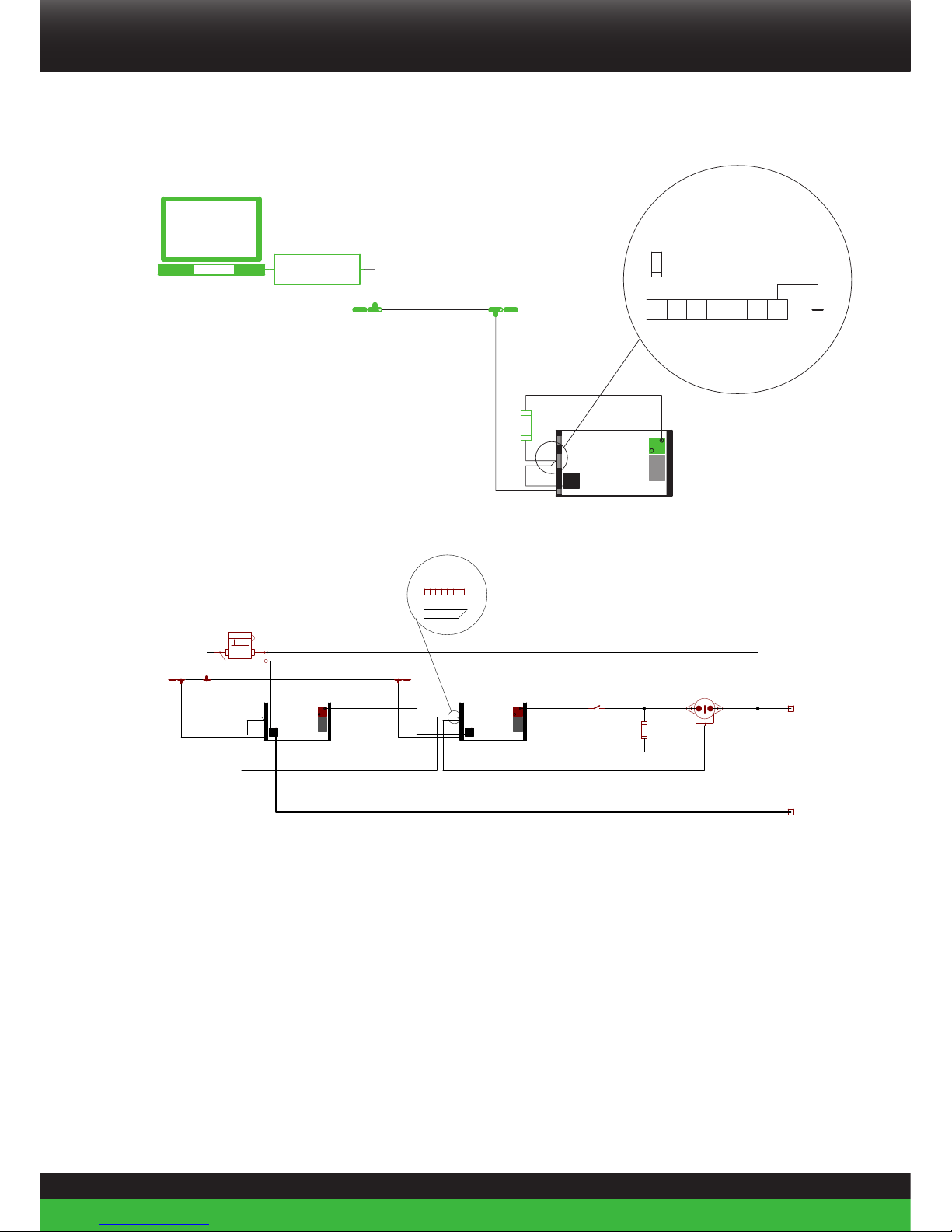
The CAN bus can be powered through Con 2 (I/O Connection 7) (figure 17) or the CAN power
cable. (figure 18)
This situation may occur when a USB-to CAN interface is directly connected to the Li-ion
battery (Figure 17).
1. Connect Pin 1 of Con2 to the + terminal of the Li-ion battery.
2. Connect Pin 7 of Con2 to the - terminal of the Li-ion battery.
29
Be in charge Super B
J2_IO
J3_CAN
J1_BREL
X1
X2
BT11
FUSE
USB
CAN
BSUBSU
CAN_Term_Female
CAN_Term_Male
V+
123
4
GND
V+ Battery
Con2
56
7
Fuse 5A
V- Battery
5A
V+
GND
+
+
_
_
Fuse
USB
Figure 17. Use Con2 to power the CAN bus
J2_IO
J3_CAN
J1_BREL
J2_IO
J3_CAN
J1_BREL
1 2
3
4
5
6
7
8 9
A
B
C
CAN_Term_Female
CAN_Term_Male
X1
X2
X1
X2
Plus
Minus
K1
Rc Rnc Rno
1 2 3
4 5 6 7
gndV+ soc nc
FUSE
FUSE
CAN
Red(+)
Black(-)
CAN Power Cable
Minus (-)
Plus (+)
Rc
RncRnc
Rc
RncRnc
Con J2 (IO connections)
Rc (pin 4)
Rnc (pin 5)
5A
Main Switch
+
+
_
_
Fuse
+
+
_
_
Fuse
A1 A2
Figure 18. Use of CAN power cable to power the CAN bus
4.7.3. CAN balancing
When the Li-ion battery is connected in a series configuration CAN balancing is required.
CAN balancing makes sure that all batteries are balanced properly. For this it is necessary
that the batteries must communicate with each other. Therefore the CAN bus is used.
CAN balancing works with SB BCI-C1/SB BIB and without SB BCI-C1/SB BIB up to 8
batteries.
Consult the manual of the SB BCI-C1/ SB BIB for more CAN balancing configurations.
30
Disconnecting the Li-ion battery
1. Turn off any device or charger the Li-ion battery is connected to.
2. Disconnect the negative wire from the - terminal of the Li-ion battery.
3. Disconnect the positive wire from the + terminal of the Li-ion battery.
5. Battery use
5.1. General information
!
Warning! Always use a Battery Disconnect device.
!
Caution! In case of an undervoltage shutdown, charge immediately.
!
Warning! Follow the safety guidelines and measures of chapter 3
5.2. Charging
!
Warning! Never charge the Li-ion battery with a charging current larger than 1C.
!
Warning! Stop charging in case the Li-ion battery switches into alarm mode. (the protection
relay will disengage)
!
Caution! Charge before use
!
Caution! Disconnect the charger from the Li-ion battery if it is not used for a long time.
!
Caution! To preserve the lifespan of the Li-ion battery, use a charger approved by Super B.
1. Connect the charger to the Li-ion battery as described in paragraph 4.6.
2. Charge the Li-ion battery in case of an under-voltage shutdown or if the state of charge
drops below 20% to preserve the lifespan of the Li-ion battery.
5.2.1. Charging rate
Super B Li-ion battery can be charged in approximately 1 hour. Displayed in Table 7 are the
charge times for the Li-ion battery at different charge currents. Always use the indicated
charge current and end of charge voltage during charging.
31
Be in charge Super B
Charging rate
Time Change current
Maximum 1 hour 1C (160A)
Endurance lifecycle 3 hours C3 (53.3A)
Table 7. Charging rates at different charge currents
5.2.2. Charging method
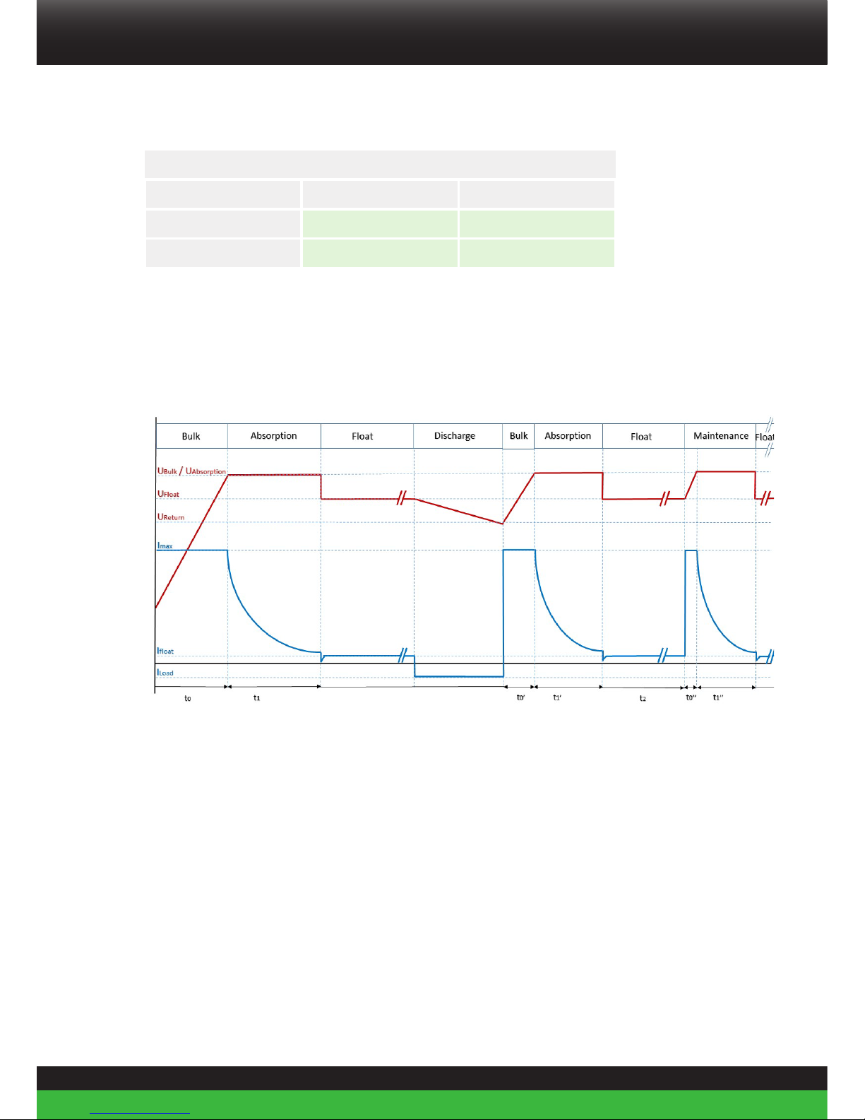
Super B recommends using the following charging method.
Charge Profile Super B Batteries
Figure 19. Charge curve
Bulk phase
In this phase the batteries are charged with a constant current up to the end of charge
voltage (Ubulk), If UBulk is reached the charger will automatically switch to absorption
phase. The maximum charge current (Imax) for Super B batteries is 1C, however for
endurance cycle life Super B suggests to limit the current to C3 (1C = nominal battery
capacity, C3 = 1/3 of nominal capacity). On some chargers the maximum charger active time
(t0) can be programmed. Super B suggests setting t0 to: t0 = 2*(BTcap / Chcur)
Example: Battery capacity = 160Ah, Charger = 80A, Set to to a maximum of 2*(160/80) = 4
hours.

32
Bulk Phase
Typical Min Max
Imax - - 1C (160 A)
t0 Depends on the battery SoC - 2*(BTcap / Chcur)
Table 8. Bulk Phase
Absorption phase
In this phase the charge voltage must be maintained at UAbsorption to fully charge the Li-ion
battery and set the State of Charge (SoC) counter to 100%. See Table 7. This phase is finished
when the SoC is indicating 100%.
Absorption Phase
Typical Min Max
UAbsorption 14.4V DC 14.3V DC 14.6V DC
t1 20 minutes 10 minutes 1 hour
Table 9. Absorption Phase
Float phase
In this phase the charge voltage is set to UFloat. The charger will supply the load, if any.
Float Phase
Typical Min Max
UFloat 13.8V DC 13.6V DC 14V DC
Table 10. Float Phase
Discharge phase
In this phase the Li-ion battery is discharged. As soon as the Li-ion battery voltage drops
below UReturn for longer than 5 seconds the charging process must be repeated.
Discharge Phase
Typical Min Max
UFloat 13.5V DC 13.4V DC 13.6V DC
Table 11. Discharge Phase

33
Be in charge Super B
Maintenance phase
Every t2 hours the batteries require a maintenance charge to fully charge the Li-ion battery
and set the State of Charge (SoC) counter to 100%. Without this phase the Li-ion battery SoC
can be inaccurate.
Maintenance Phase
Typical Max
t3 13 weeks 26 weeks
Table 12. Maintenance phase
5.2.3. Battery balancing
The Li-ion battery is automatically balanced during the absorption phase (see paragraph
5.2.2).
During the batteries lifespan, the cells within the Li-ion battery may be unbalanced due to
high discharge currents and short float charge periods. This may result in a loss of capacity
and unbalanced cells. Cells may be equalized by means of the following procedure:
Apply a constant voltage of 14.4V and a current of between 1A and 2A to manually equalize
the Li-ion battery.
5.2.4. Reading out the battery’s State of Charge (SoC)
The Li-ion battery’s State of Charge can be read out either by using the BM01, Touch Display,
CAN network, or by the analogue output (see further instructions below).
1. Connect Pin1 of Con2 to the Li-ion battery’s + pole.
2. Connect Pin 7 of Con2 to ground.
3. Determine the voltage at Pin 2 of CON2 (see Figure 20).
The analog SoC output ranges from 0 to 10 volt, in which 0V corresponds with 0% SoC and 10V
corresponds with 100% SoC.
The SoC is an indication. Charging currents smaller than 100mA are not used in the SoC calculation.
4. Perform a complete charge cycle to the Li-ion battery through if the SoC indication does not provide an
accurate measurement. This will recalibrate the SoC.

34
21 3 4 5 6 7
V+
GND
GND
V
con 2
Fuse 5A
Figure 20. Determining the batteries SoC
5.3. Battery Monitoring Software
Battery monitoring software offers the possibility to continuously monitor a number of the
Li-ion battery properties through sensors within the Li-ion battery. It also enables one to
download a complete recording of the Li-ion battery’s properties over time.
The Battery Monitoring software and the hardware are not included with the Li-ion battery.
An overview of these products is given in paragraph 2.8.2.
5.3.1. Battery History Recording
The battery history can be downloaded with the Battery Monitor software. Thisrecording can
only be accessed by a reseller or Super B for evaluation.

35
Be in charge Super B
6. Inspection, cleaning and maintenance
6.1. General information
!
Warning! Never attempt to open or dismantle the Li-ion battery! The inside of the Li-ion
battery does not contain serviceable parts.
1. Disconnect the Li-ion battery from all loads and charging devices before performing cleaning and
maintenance activities (see paragraph 4.7.5).
2. Remove the fuse or dummy fuse before cleaning and maintenance activities (see paragraph 4.3.2).
3. Place the enclosed protective caps over the terminals before cleaning and maintenance activities to
avoid the risk of contacting the terminals.
6.2. Inspection
1. Inspect for loose and/or damaged wiring and contacts, cracks, deformations, leakage or damage of any
other kind. If damage to the Li-ion battery is found, it must be replaced. Do not attempt to charge or
use a damaged Li-ion battery. Do not touch the liquid from a ruptured Li-ion battery
2. Observe and note the run time that a new, fully-charged Li-ion battery provides for powering your
product. Use this new Li-ion battery run time as a basis to compare run times for older batteries. The
run time of the Li-ion battery will vary depending on the products’ configuration and the application it is
used for.
3. Routinely check the Li-ion battery’s charge status. Lithium Iron Phosphate batteries continue to slowly
self-discharge (1-2% per month) when not in use or whilst in storage.
4. Carefully monitor batteries that are approaching the end of their estimated life.
5. Consider replacing the Li-ion battery with a new one if you note either of the following conditions:
- The Li-ion battery run time drops below about 80% of the original run time.
- The Li-ion battery charge time increases significantly.
6.3. Cleaning
If necessary, clean the Li-ion battery with a soft, dry cloth. Never use liquids, solvents, or
abrasives to clean the Li-ion battery.

36
7. Storage
Follow the storage instructions in this manual to optimize the lifespan of the Li-ion battery
during storage. If these instructions are not followed and the Li-ion battery has no charge
remaining when it is checked, consider it to be damaged. Do not attempt to recharge or use
it. Replace it with a new Li-ion battery.
See chapter 2.4 for storage temperature conditions.
The self-discharge of the Li-ion battery is 1-2% per month.
1. Charge the Li-ion battery to 100% of its capacity before storage.
2. Disconnect the Li-ion battery from all loads and, if present, the charging device
3. Remove the fuse from the Li-ion battery during storage. (See paragraph 4.3.2)
4. Place the terminal covers over the Li-ion battery’s terminals during storage.
5. Charge the Li-ion battery to 100% of its capacity every year.
8. Transportation
8.1. General
Always check all applicable local, national, and international regulations before transporting
a Lithium Iron Phosphate battery.
Transporting an end-of-life, damaged, or recalled Li-ion battery may, in certain cases, be
specifically limited or prohibited.
The transport of the Li-ion battery falls under hazard class UN3480, class 9. For transport over
water, air and land, the Li-ion battery falls within packaging group PI965 Section II.
Use Class 9 Miscellaneous Dangerous Goods and UN Identification labels for
transportation of lithium ion batteries which are assigned Class 9. Refer to
relevant transportation documents. Lithium batteries and lithium ion cells are
regulated in the U.S. in accordance with Part 49 of the Code
of Federal Regulations, (49 CFR Sections 105-180) of the U.S. Hazardous
Materials Regulations.
Visit www.iata.org for the complete transport regulations and packing instructions for this
product. The relevant information for Li-ion batteries can be found under “Programs” >
“Cargo” > “Dangerous goods (HAZMAT)”.

37
Be in charge Super B
9. Disposal and recycling
9.1. General information
Always discharge the Li-ion battery before disposal. Use electrical tape or other approved
covering over the Li-ion battery connection points to prevent short circuits.
Battery recycling is encouraged. Dispose of the Li-ion battery in accordance with local, state
and federal laws and regulations. Batteries may be returned to the manufacturer.
USA & Canada:
Lithium Iron Phosphate batteries are subject to disposal and recycling regulations that vary
by country and region. Always check and follow your applicable regulations before disposing
of any Li-ion battery. Contact Rechargeable Battery Recycling Corporation (www.rbrc.org) for
U.S.A. and Canada, or your local Li-ion battery recycling organization.
EC
Waste must be disposed of in accordance with relevant EC Directives and national, regional
and local environmental control regulations. For disposal within the EC, the appropriate code
according to the European Waste Catalogue (EWC) should be used.
Other
Many countries prohibit the disposal of waste electronic equipment in standard waste
receptacles.

38
10. Troubleshooting
Problem Possible reason Solution
The capacity of
the Li-ion battery
has decreased
The cells within the batteries are not
properly balanced or the Li-ion battery
is worn out. .
Perform one full charge cycle to
balance the cells.
The Li-ion
battery cannot
be charged /
discharged
The fuse of the Li-ion battery is not
installed
Install the fuse; follow the procedures
described in paragraph 4.3.2
The fuse in the Li-ion battery is
broken.
Disconnect all loads and chargers,
check and correct for short circuits
and defects. Then replace the fuse;
follow the procedures described in
paragraph 4.3.2
The Li-ion battery has been deeply
discharged. The BMS is now in “fault
condition”.
Disconnect all loads and connect a
charger to the Li-ion battery. Then
press the reset button for at least
10-15 seconds to resolve the “fault
condition”(see paragraph 2.7.).
The Li-ion battery has been
overcharged. The BMS is now in
“fault condition”.
Disconnect the charger from the Liion battery and press the reset button
for at least 10-15 seconds to resolve
the “fault condition” (see paragraph
2.7.).
The Li-ion battery has overheated.
The BMS is now in “fault condition”.
Disconnect the charger and all loads
and wait for the Li-ion battery to cool
down. Then press the reset button for
at least 10-15 seconds to resolve the
“fault condition” (see paragraph 2.7.).
Table 13. Troubleshooting

39
Be in charge Super B
11. Warranty and liability
11.1 Upon delivery the customer is obliged to immediately verify whether the products have
been damaged during transport. In the event that any such damage has arisen, the customer
must notify Super B thereof as soon as possible, in any event no later than three (3) days of
delivery, by means of accurate, written statement, stating the damage and where possible a
photograph. Failure to inspect the products and inform Super B within the stated time or the
use of the products at any time shall be conclusive evidence that Super B has satisfactorily
tendered delivery.
11.2 In the event that the customer demonstrates that any of the delivered products do not
conform to the agreement, Super B (at its option, upon having received those products returned
by the customer) has the option to either repair or replace such products by new products, or to
refund the invoice value, exclusive of any dispatch costs.
11.3 Super B grants a three year limited warranty for damages caused by manufacturing
defects starting at the time of delivery. Damages caused by manufacturing defects do not
include damage resulting from (a) general wear and tear, (b) short circuit, (c) overcharging, (d)
deep discharging, (e) overheating of Super B products (f) installation of the Super B product by
persons unskilled to work with electro-technical devices or components, (g) any other wrongful
use contrary to the Super B’s user manual or the safety instruction, (h) any use contrary to the
product specifications of that product; (i) any acts of force majeure.
11.4 Except as specified in the clause 11.3 Super B makes no warranty, whether express or
implied, including without limitation any implied warranty of merchantability and fitness for a
particular purpose or any warranty arising from any course of dealing, course of performance
or usage of trade and specifically disclaims any representation or warranty that the product will
meet customer’s requirements, perform any specific function or achieve a desired result other
than expressly stated by Super B in writing.
11.5 Any liability to the customer in any case ceases to apply in the event that the customer
fails to notify Super B of the existence of the defect within ten (10) days of having discovered
the defect, in writing, in order to enable Super B to investigate the damage. Some of Super
B’s products electronically store usage data, including charging/discharging data, in order to
enable Super B to analyse such data retroactively when investigating damage.
11.6 Any liability of Super B for damage suffered by the customer is in any case limited to
the invoice amount of the relevant products, unless such damage has been caused by gross
negligence or willful misconduct of Super B.

40
Super B can never be held liable for (a) damage caused by any of the circumstances mentioned
in clause 11.3, leading to damage to the Super B products or to any other device located near
those products, or (b) consequential damage or (c) loss of profits or goodwill.
11.7 To the extent that a court determines that the limitation of liability as meant in clause
11.6 cannot be invoked against a particular claim for damages by the customer, Super B’s
liability for loss of property, damage to property, and bodily injury (including death) caused
by the application of those particular Super B products shall in any event be limited to the
amount actually paid out by Super B’s insurance company to Super B in accordance with the
insurance cover of that insurance policy for that particular type of damage. Super B has taken
out insurance against certain risks, as described in the respective insurance policies. These
policies contain a usual limitation of insurance payment to be paid out to Super B if, and to the
extent that, the event is a covered event.

41
Be in charge Super B
Appendix I. Declaration of Conformity
42
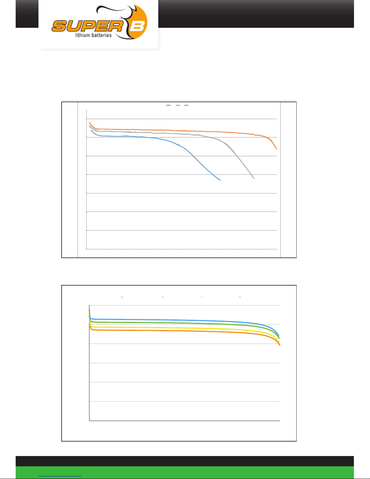
Appendix II. Performance Graphs
Temperature performance
0
2
4
6
8
10
12
14
0 10 20 30 40 50 60 70 80 90 100
U(V)
Capacity(%)
-10℃ 0℃ 23℃
Load performance
U(V)
0
2,5
5
7,5
10
12,5
15
Capacity (%)
0112131405060708090100
0,5C 1C 2C 3C

43
Be in charge Super B
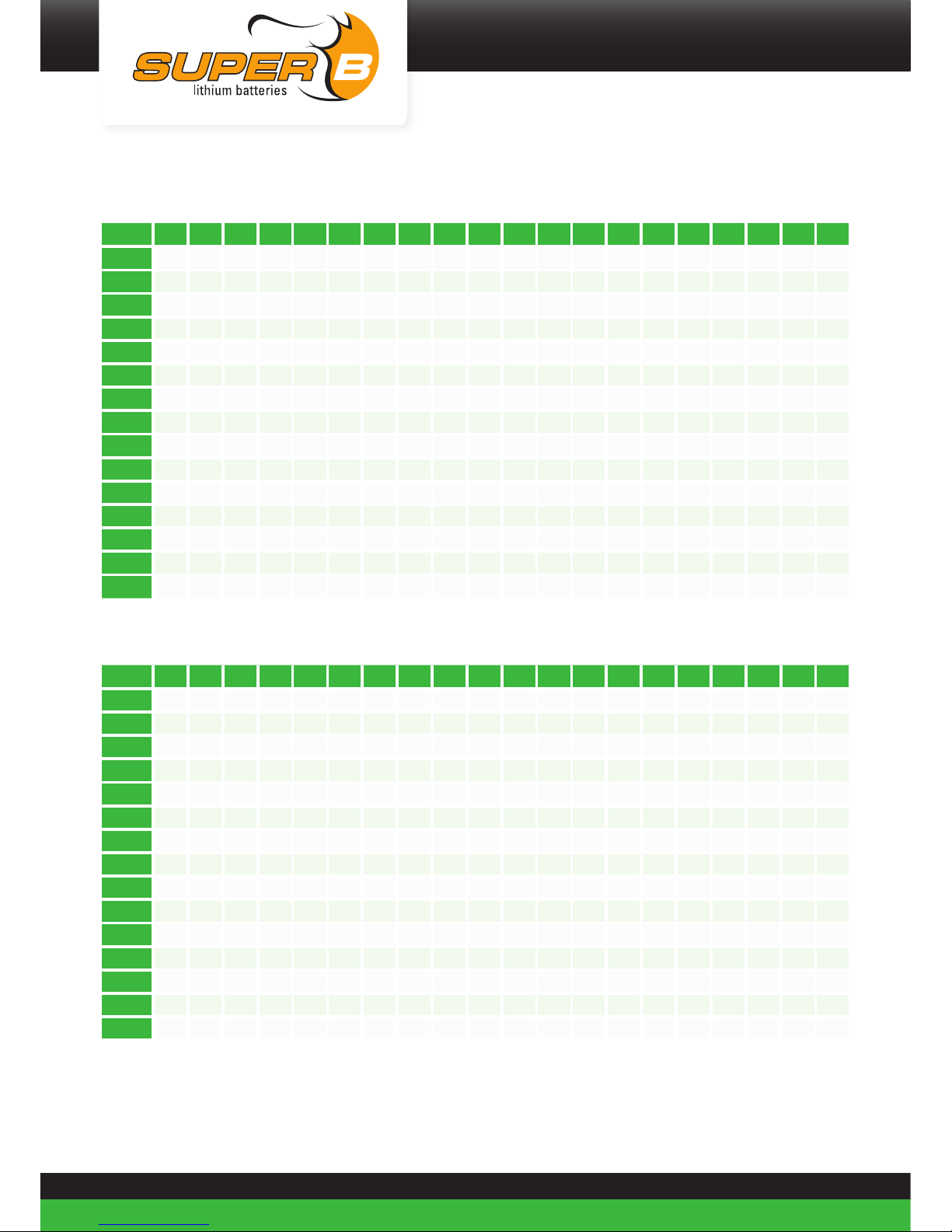
Appendix III. Conductor requirements
Subject
Use appropriate wire for the connection wires to ensure no overheating or unnecessary
losses occur. Consult the SAE-J378 or ISO 10133:2012 standards to determine the appropriate
wire properties. Use appropriate fuses matching the wires and load.
The below information is a summary extracted from the ISO10133:2012, reading the
ISOISO10133:2012 is recommended.
Conductor requirements 12V d.c. system at 30 °C ambient temperature
Allowable maximum current, in amperes, for single conductors at insulation temperature
ratings. With a maximum voltage drop of 3%.
S is the conductor cross-sectional area, in square millimeters
I is the load current, in amperes
L is the length, in meters, of conductor from the positive power source to the electrical
device and back to the negative source connection.
Conductors at insulation temperature 105 ºC:
S / L 1 2 3 4 5 6 7 8 9 10 15 20 25 30 35 40 45 50 75 100
0,75 16 8 5 4 3 3 2 2 2 2 1 1 1 1 0 0 0 0 0 0
1 22 11 7 5 4 4 3 3 2 2 1 1 1 1 1 1 0 0 0 0
1,5 33 16 11 8 7 5 5 4 4 3 2 2 1 1 1 1 1 1 0 0
2,5 45 27 18 14 11 9 8 7 6 5 4 3 2 2 2 1 1 1 1 1
4 55 44 29 22 18 15 13 11 10 9 6 4 4 3 3 2 2 2 1 1
6 75 66 44 33 26 22 19 16 15 13 9 7 5 4 4 3 3 3 2 1
10 120 110 73 55 44 37 31 27 24 22 15 11 9 7 6 5 5 4 3 2
16 170 170 117 88 70 59 50 44 39 35 23 18 14 12 10 9 8 7 5 4
25 200 200 183 137 110 91 78 69 61 55 37 27 22 18 16 14 12 11 7 5
35 240 240 240 192 154 128 110 96 85 77 51 38 31 26 22 19 17 15 10 8
50 325 325 325 274 220 183 157 137 122 110 73 55 44 37 31 27 24 22 15 11
70 375 375 375 375 307 256 220 192 171 154 102 77 61 51 44 38 34 31 20 15
95 430 430 430 430 417 348 298 261 232 209 139 104 83 70 60 52 46 42 28 21
120 520 520 520 520 520 439 376 329 293 263 176 132 105 88 75 66 59 53 35 26
150 560 560 560 560 560 549 470 412 366 329 220 165 132 110 94 82 73 66 44 33

44
Conductors at insulation temperature 85 - 90 ºC:
S / L 1 2 3 4 5 6 7 8 9 10 15 20 25 30 35 40 45 50 75 100
0,75 16 8 5 4 3 3 2 2 2 2 1 1 1 1 0 0 0 0 0 0
1
22 11
7
5 4
4 3
3
2 2
1 1
1
1 1
1 0
0
0 0
1,5 30 16 11 8 7 5 5 4 4 3 2 2 1 1 1 1 1 1 0 0
2,5 40 27 18 14 11 9 8 7 6 5 4 3 2 2 2 1 1 1 1 1
4
50 44 29 22 18 15 13 11 10 9 6 4 4 3 3 2 2 2 1 1
6 70 66 44 33 26 22 19 16 15 13 9 7 5 4 4 3 3 3 2 1
10 100 100 73 55 44 37 31 27 24 22 15 11 9 7 6 5 5 4 3 2
16 150 150 117 88 70 59 50 44 39 35 23 18 14 12 10 9 8 7 5 4
25 185 185 183 137 110 91 78 69 61 55 37 27 22 18 16 14 12 11 7 5
35 225 225 225 192 154 128 110 96 85 77 51 38 31 26 22 19 17 15 10 8
50 300 300 300 274 220 183 157 137 122 110 73 55 44 37 31 27 24 22 15 11
70 360 360 360 360 307 256 220 192 171 154 102 77 61 51 44 38 34 31 20 15
95 410 410 410 410 410 348 298 261 232 209 139 104 83 70 60 52 46 42 28 21
120 480 480 480 480 480 439 376 329 293 263 176 132 105 88 75 66 59 53 35 26
150 520 520 520 520 520 520 470 412 366 329 220 165 132 110 94 82 73 66 44 33
Conductors at insulation temperature 70 ºC:
S / L 1 2 3 4 5 6 7 8 9 10 15 20 25 30 35 40 45 50 75 100
0,75 16 8 5 4 3 3 2 2 2 2 1 1 1 1 0 0 0 0 0 0
1 20 11 7 5 4 4 3 3 2 2 1 1 1 1 1 1 0 0 0 0
1,5 25 16 11 8 7 5 5 4 4 3 2 2 1 1 1 1 1 1 0 0
2,5 35 27 18 14 11 9 8 7 6 5 4 3 2 2 2 1 1 1 1 1
4 45 44 29 22 18 15 13 11 10 9 6 4 4 3 3 2 2 2 1 1
6 60 60 44 33 26 22 19 16 15 13 9 7 5 4 4 3 3 3 2 1
10 90 90 73 55 44 37 31 27 24 22 15 11 9 7 6 5 5 4 3 2
16 130 130 117 88 70 59 50 44 39 35 23 18 14 12 10 9 8 7 5 4
25 170 170 170 137 110 91 78 69 61 55 37 27 22 18 16 14 12 11 7 5
35 210 210 210 192 154 128 110 96 85 77 51 38 31 26 22 19 17 15 10 8
50 270 270 270 270 220 183 157 137 122 110 73 55 44 37 31 27 24 22 15 11
70 330 330 330 330 307 256 220 192 171 154 102 77 61 51 44 38 34 31 20 15
95 390 390 390 390 390 348 298 261 232 209 139 104 83 70 60 52 46 42 28 21
120 450 450 450 450 450 439 376 329 293 263 176 132 105 88 75 66 59 53 35 26
150 475 475 475 475 475 475 470 412 366 329 220 165 132 110 94 82 73 66 44 33

45
Be in charge Super B
Conductor requirements 48V d.c. system at 30 °C ambient temperature
Allowable maximum current, in amperes, for single conductors at insulation temperature
ratings. With a maximum voltage drop of 3%.
S is the conductor cross-sectional area, in square millimeters
I is the load current, in amperes
L is the length, in meters, of conductor from the positive power source to the electrical
device and back to the negative source connection.
Conductors at insulation temperature 105 ºC:
S / L 1 2 3 4 5 6 7 8 9 10 15 20 25 30 35 40 45 50 75 100
0,75 12 8 5 4 3 3 2 2 2 2 1 1 1 1 0 0 0 0 0 0
1 18 11 7 5 4 4 3 3 2 2 1 1 1 1 1 1 0 0 0 0
1,5 21 16 11 8 7 5 5 4 4 3 2 2 1 1 1 1 1 1 0 0
2,5 30 27 18 14 11 9 8 7 6 5 4 3 2 2 2 1 1 1 1 1
4 40 40 29 22 18 15 13 11 10 9 6 4 4 3 3 2 2 2 1 1
6 50 50 44 33 26 22 19 16 15 13 9 7 5 4 4 3 3 3 2 1
10 70 70 70 55 44 37 31 27 24 22 15 11 9 7 6 5 5 4 3 2
16 100 100 100 88 70 59 50 44 39 35 23 18 14 12 10 9 8 7 5 4
25 140 140 140 137 110 91 78 69 61 55 37 27 22 18 16 14 12 11 7 5
35 185 185 185 185 154 128 110 96 85 77 51 38 31 26 22 19 17 15 10 8
50 230 230 230 230 220 183 157 137 122 110 73 55 44 37 31 27 24 22 15 11
70 285 285 285 285 285 256 220 192 171 154 102 77 61 51 44 38 34 31 20 15
95 330 330 330 330 330 330 298 261 232 209 139 104 83 70 60 52 46 42 28 21
120 400 400 400 400 400 400 376 329 293 263 176 132 105 88 75 66 59 53 35 26
150 430 430 430 430 430 430 430 412 366 329 220 165 132 110 94 82 73 66 44 33
46
Conductors at insulation temperature 85 - 90 ºC:
S / L 1 2 3 4 5 6 7 8 9 10 15 20 25 30 35 40 45 50 75 100
0,75 10 8 5 4 3 3 2 2 2 2 1 1 1 1 0 0 0 0 0 0
1
14 11
7
5 4
4 3
3
2 2
1 1
1
1 1
1 0
0
0 0
1,5 18 16 11 8 7 5 5 4 4 3 2 2 1 1 1 1 1 1 0 0
2,5 25 25 18 14 11 9 8 7 6 5 4 3 2 2 2 1 1 1 1 1
4
35 35 29 22 18 15 13 11 10 9 6 4 4 3 3 2 2 2 1 1
6 45 45 44 33 26 22 19 16 15 13 9 7 5 4 4 3 3 3 2 1
10 65 65 65 55 44 37 31 27 24 22 15 11 9 7 6 5 5 4 3 2
16 90 90 90 88 70 59 50 44 39 35 23 18 14 12 10 9 8 7 5 4
25 120 120 120 120 110 91 78 69 61 55 37 27 22 18 16 14 12 11 7 5
35 160 160 160 160 154 128 110 96 85 77 51 38 31 26 22 19 17 15 10 8
50 210 210 210 210 210 183 157 137 122 110 73 55 44 37 31 27 24 22 15 11
70 265 265 265 265 265 256 220 192 171 154 102 77 61 51 44 38 34 31 20 15
95 310 310 310 310 310 310 298 261 232 209 139 104 83 70 60 52 46 42 28 21
120 360 360 360 360 360 360 360 329 293 263 176 132 105 88 75 66 59 53 35 26
150 380 380 380 380 380 380 380 380 366 329 220 165 132 110 94 82 73 66 44 33
Conductors at insulation temperature 70 ºC:
S / L 1 2 3 4 5 6 7 8 9 10 15 20 25 30 35 40 45 50 75 100
0,75 6 6 5 4 3 3 2 2 2 2 1 1 1 1 0 0 0 0 0 0
1 8 8 7 5 4 4 3 3 2 2 1 1 1 1 1 1 0 0 0 0
1,5 12 12 11 8 7 5 5 4 4 3 2 2 1 1 1 1 1 1 0 0
2,5 17 17 17 14 11 9 8 7 6 5 4 3 2 2 2 1 1 1 1 1
4 22 22 22 22 18 15 13 11 10 9 6 4 4 3 3 2 2 2 1 1
6 29 29 29 29 26 22 19 16 15 13 9 7 5 4 4 3 3 3 2 1
10 40 40 40 40 40 37 31 27 24 22 15 11 9 7 6 5 5 4 3 2
16 54 54 54 54 54 54 50 44 39 35 23 18 14 12 10 9 8 7 5 4
25 71 71 71 71 71 71 71 69 61 55 37 27 22 18 16 14 12 11 7 5
35 87 87 87 87 87 87 87 87 85 77 51 38 31 26 22 19 17 15 10 8
50 105 105 105 105 105 105 105 105 105 110 73 55 44 37 31 27 24 22 15 11
70 135 135 135 135 135 135 135 135 135 135 102 77 61 51 44 38 34 31 20 15
95 165 165 165 165 165 165 165 165 165 165 139 104 83 70 60 52 46 42 28 21
120 190 190 190 190 190 190 190 190 190 190 176 132 105 88 75 66 59 53 35 26
150 220 220 220 220 220 220 220 220 220 220 220 165 132 110 94 82 73 66 44 33

47
Be in charge Super B
Derating of conductors in ambient temperatures of 60 °C
For conductors in 60 °C ambient, the maximum current rating in the above tables shall be
derated by the factors below.
Temperature rating of conductor insulation,°C Multiply maximum current from Table by:
70 0,75
85 – 90 0,82
105 0,86
125 0,89
200 1
Table 14. Derating of conductors

LI-ION
For more information, or to order documents,
contact:
Super B
Expolaan 50
7556 BE Hengelo (Ov)
The Netherlands
Tel: +31(0)748200014 (support)
E-mail: support@super-b.com
www: www.super-b.com
Manual June 2018
 Loading...