

Superabrasive Lavina 20NHV Pro, Lavina 20N Pro, Lavina 20 Pro Owner's Manual
Superabrasive Owner’s Manual orginal language – Lavina 20®N Pro/20®NHV Pro 2/2012
A
N
I
V
A
L
L
L
A
A
V
V
I
I
N
N
A
A
2
2
2
0
0
0
®
®
®
N
N
N
P
P
P
r
r
r
o
o
o
/
2
0
®
N
H
V
P
r
/
2
0
®
N
H
V
/
2
0
®
N
H
V
P
P
r
r
o
o
o

Superabrasive Owner’s Manual orginal language – Lavina 20®N Pro/20®NHV Pro 2/2012
CONTENT
1. GENERAL INFORMATION
Preface 3
Manufacturer 3
General Description 3
Machine Characteristics 3
Lavina20® Pro Main Design 3
Environmental Conditions 4
Electrical Connection 4
Vacuum Connection 4
Technical Data 4
Vibrations 4
Sonorous Emissions 4
Label Data 4
Customer Service 4
2. SAFETY INSTRUCTIONS
Recommended Use 4
Prohibited Use 4
Preparation for Work 5
Protection Devices 5
Arrest Functions 5
Safe Use 5
Residual Risks 5
Before You Begin 5
Operating the Machine 5
After Work is Completed 5
The Work Area 5
Personal Protective Equipment (Ppe) 5
Operator 5
3. HANDLING AND TRANSPORTATION
Preparing the Machine for Transportation 6
Storage 6
4. OPERATION
Preliminary Controls 7
Adjusting and Mounting Tools 7
Control Board 7
Starting the Machine 7
Operating Machine 7
Stopping Machine 7
Alarm 7
5. TOOLS AND ACCESSORIES
Weights 8
Belt Replacing Tool 8
Tool Holder Key 8
Foam Plate 8
6. POPULAR TOOLS 9
7. MAINTENANCE AND INSPECTION
Cleaning 10
Check Daily 10
Check Every 200 Working Hours 10
Check Every 400 Working Hours 10
Vacuum 10
Water Leaks 10
Mechanical Parts 10
Electrical System 10
Single Phase or Three Phase Connection 10
Electrical Schemes 208-240 Volt 11
Electrical Schemes 380-480 Volt 11
8. TROUBLESHOOTING
Index of Problems and Solutions
Replacing Power Cord and Plugs 13
Dismounting and Mounting SA Tool Holder 13
Dismounting and Mounting SAM Tool Holder 14
Replacing Belt and Pulley Units with Pins 14
Replacing Belt and Pulley Units with SA or SAM Tool Holder 15
Replacement of the Pulley Units 16
Mounting the Belt with Pins 17
Mounting the Belt with SA or SAM Tool Holder 17
Motor Connection 17
Fault Diagnosis Inverter YASKAWA V1000 18
9. WARRANTY, WARRANTY CARD AND RETURNS
Warranty 21
Return Policy 21
10. DISPOSAL 21
11. MANUFACTURER’S CONTACTS 21
12. SPARE PARTS
Assembly and Parts Specifications 22
Assembly and Parts Specifications Main Head
for Machines with Short Shaft Motor 22
Assembly and Parts Specifications Main Head
for Machines with Long Shaft Motor 23
Assembly and Parts Specifications of the Main Head
Seal Assembly with Pins for Machines with Numbers 24
Assembly and Parts Specifications of the Main Head
Seal Assembly with SA Tool Holder f Machines w Numbers 25
Assembly and Parts Specifications of the Main Head
Seal Assembly with SAM Tool Holder f Machines w Numbers 26
Assembly and Parts Specifications of the Main Head
Bottom Cover Assembly for Machines with Short Shaft Motor 27
Assembly and Parts Specifications of the Main Head
Bottom Cover Assembly for Machines with Numbers 27
Assembly and Parts Specifications of the Main Head
Bottom Cover Assembly for Machines with Numbers 28
Assembly and Parts Specifications of the Main Head
Bottom Cover Machines with Number 28
Assembly and Parts Specifications of the Main Head M and W Support 29
Assembly and Parts Specifications of the Main Head Top Cover 29
Assembly and Parts Specifications of the Main Head
Disc Assembly for Machines with Short Shaft Motor 30
Assembly and Parts Specifications of the Main Head
Disc Assembly for Machines with Numbers 30
Assembly and Parts Specifications of the Main Head
Disc Assembly for Machines with Numbers 31
Assembly and Parts Specifications of the Main Head Pulley Unit 32
Assembly and Parts Specifications of the Main Head Base Plate 33
Assembly and Parts Specifications of the Main Head Guard Assembly 33
Assembly and Parts Specifications of the Carriage 34
Floating Backer Plate Tool Holder 34
SA Tool Holder 35
SAM Tool Holder 36
Lavina20®N Pro Assembly and Parts
Specifications of the Electrical and Control Box 208-240 Volt 37
Lavina20®NHV Pro Assembly and Parts
Specifications of the Electrical and Control Box 380-480 Volt 38
2
Superabrasive Owner’s Manual orginal language – Lavina 20®N Pro/20®NHV Pro 2/2012
1. GENERAL INFORMATION
This owner’s manual is intended for the operator of the Lavina 20®N Pro/20®NHV Pro machine, the servicing
technician as well as for anyone involved with operating or servicing the machine. We recommend that you read the
instructions very carefully and follow them strictly. The manual includes information about assembling, using, handling,
adjusting and maintaining your Lavina 20®N Pro/20®NHV Pro floor grinding and polishing machine.
MANUFACTURER
Superabrasive was founded 24 years ago, in 1987, as a manufacturer of high quality diamond tools for the stone and
concrete industry. Today, Superabrasive is one of the world’s leading companies in the production of diamond tools and
floor grinding machinery. At Superabrasive, we strive to deliver the very best solutions to our customers, and enable
them to work more efficiently.
GENERAL DESCRIPTION
The Lavina 20®N Pro/20®NHV Pro machine is intended for grinding, polishing and buffing concrete, marble, granite,
limestone and terrazzo surfaces with diamond tools.
The Lavina 20®N Pro/20®NHV Pro is a three-disc machine, which can be used dry as well as wet.
For best results, use only tools manufactured or recommended by Superabrasive and its distributors. Additionally, the
machine could be used for grinding wood floor surfaces.
WARNING!
The Lavina 20®N Pro/20®NHV Pro machine is manufactured and fitted for the above-mentioned applications only!
Every other use may possess risks to the persons involved.
MACHINE CHARACTERISTICS
The Lavina 20®N Pro/20®NHV Pro is made of two main component sections:
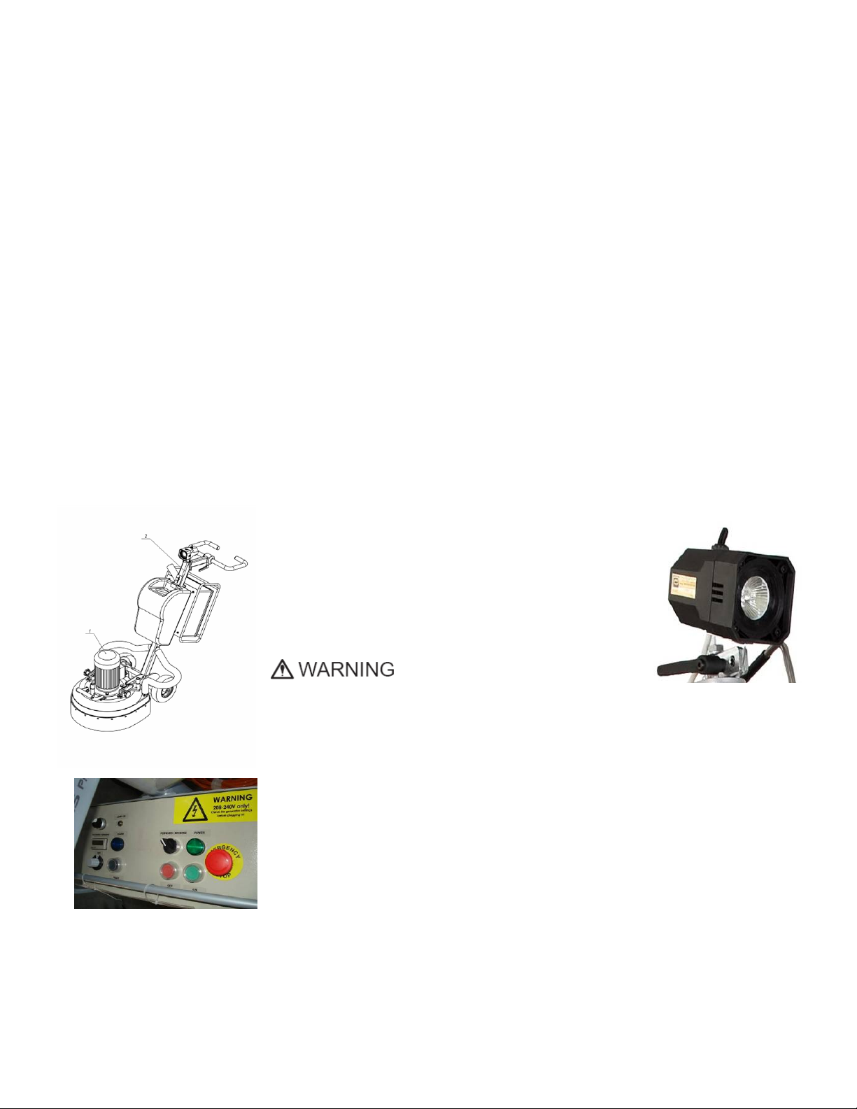
LAVINA 20®N PRO/20®NHV PRO MAIN DESIGN
• The two main component sections, the
carriage and main head.
The handle on the frame is adjustable in height and
allows the operator to work in a correct and safe
posture.
• The halogen spotlight (Fig.1.2) enables the
operator to work in darker areas.
Existing lighting system does
not replace adequate overhead lighting.
• The frame
• The controls are positioned on top of the electrical box (fig.1.3)
Figure 1.1
• The electrical box (fig.1.3) contains the electric switching devices and the
inverter. The motor feeding cable and the main feeding cable are plugged in the socket
located on the bottom of the box.
• The water tank is on the opposite side of the frame, so that the weight of the
water has no influence on the operation of the machine. The frame weight, on the
other hand, is fully absorbed by the driving wheels.
• The motor is mounted on the base plate and is driving the three heads with a belt
Figure 1.3
system. The planetary motion derives from the friction between the tools and the
floor, which is allowing the tools to spin in either clockwise or counterclockwise
direction. The design ensures that the tools will not force themselves against the resistance of the floor surface.
Instead, the machine will alternate directions to accommodate to a “high spot” or a “low spot” imperfections in the
floor without causing damage to the floor or the machine.
Figure 1.2
Superabrasive Owner’s Manual orginal language – Lavina 20®N Pro/20®NHV Pro 2/2012
ENVIRONMENTAL CONDITIONS
The temperature range for operating the Lavina 20®N Pro/20®NHV Pro outdoors is between 41°F and 86°F or 5°C and
30°C. Never use the Lavina 20®N Pro/20®NHV Pro during rain or snow when working outdoors. When working
indoors, always operate the machine in well-ventilated areas.
ELECTRICAL CONNECTION
The voltage (Volt) and power (Ampere) are displayed on a label on the electrical control box to avoid any incorrect
connection. Refer to these before connecting the power. To avoid electrical shocks, make sure the ground power
supply is functioning properly.
VACUUM CONNECTION
A connection for a vacuum dust extractor is located on the carriage. The Lavina 20®N Pro/20®NHV Pro does not
include a vacuum dust extractor. The customer must purchase the vacuum dust extractor separately. The hose of the
vacuum extractor must be Ø 50 mm and can be glided over the pipe. The vacuum dust extractor must be adapted for
floor grinders and have a minimum air displacement of 320m3/h with a negative vacuum of 21 kPa.
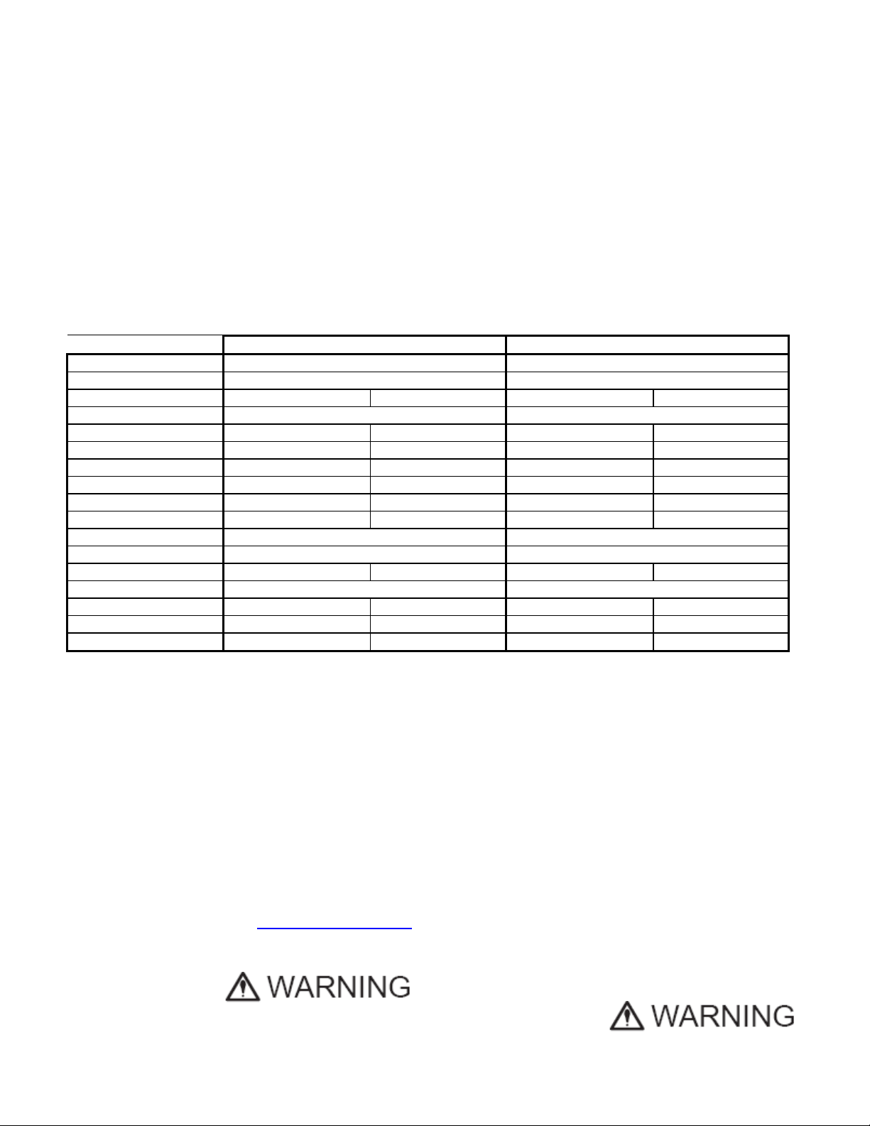
TECHNICAL DATA
Lavina 20®N Pro Lavina 20®NHV Pro
Voltage/Hz 1or 3 ph x 208-240 V 50-60Hz 3 ph x 380-480 V 50-60Hz
Amperage Max 15 Amps Max 14 Amps
Power 5,5 kW 7,5 HP 5,5 kW 7,5 HP
Tool holder rpm 300-1100 rpm 300-1100 rpm
Working width 510 mm 20” 510 mm 20”
Tool holder diameter 3x 165 mm 3x 6.5” 3x 165 mm 3x 6.5”
Tool diameter 3x 225 mm 3x 9” 3x 225 mm 3x 9”
Weight 153 kg 337 lbs 153 kg 337 lbs
Grinding pressure 98 kg 216 lbs 98 kg 216 lbs
Additional weight max 2x 22 kg max 96 lbs max 2x 22 kg max 96 lbs
Application wet and dry wet and dry
Vacuum hose port Yes Yes
Water tank capacity 16 l 4.2 gal 16 l 4.2 gal
Water feed Peripheral Peripheral
Cable length 17.4 m 57 ft 17.4 m 57 ft
Machine LxWxH 1350x540x1100 mm 53.1”x21.3”x43.3” 1350x540x1100 mm 53.1”x21.3”x43.3”
Packing LxWxH 1150x730x1155 mm 45.2”x28.7”x45.5” 1150x730x1155 mm 45.2”x28.7”x45.5”
VIBRATIONS
The vibrations of the machine are within the limits of directive 2003/10/EC (the seventeenth Individual Directive of
Article 16(1) of Directive 89/391/EC) if the Lavina 20®N Pro/20®NHV Pro is operated with the recommended tools and
in normal conditions.
SONOROUS EMISSIONS
Sonorous emissions are also within the limits of directive 2003/10/EC (the seventeenth individual Directive of Article
16(1) of Directive 89/391/EC). However, as previously stated, the operator must wear ear protectors.
LABEL DATA
The data on the label provides the correct voltage and kW (needed for operational purposes);
Weight (needed for transportation purposes); production year and serial number (needed for maintenance purposes).
CUSTOMER SERVICE
For customer assistance and technical support call your local distributor or call Superabrasive Inc. at
1-800-987-8403 or visit us at: www.superabrasive.com
, where you can download a copy of this manual.
2. SAFETY INSTRUCTIONS
RECOMMENDED USE
The Lavina 20N Pro/20NHV Pro machine is designed and
manufactured to grind and polish concrete, terrazzo and natural
stone floors. It can be used for renovations as well as for
polishing. The machine is designed for dry or wet use. When
using it dry, use a vacuum of appropriate size. For more
4
information, please refer to the chapter on handling the vacuum
connection.
PROHIBITED USE
The machine MUST NOT be used:
• For applications different from the ones stated in the
General Description chapter.

Superabrasive Owner’s Manual orginal language – Lavina 20®N Pro/20®NHV Pro 2/2012
• For not-suitable materials.
• In environments which:
• Possess risks of explosion
• Possess high concentration of powders or oil substances in
the air
• Possess risks of fire
• Feature inclement conditions.
• Possess electromagnetic radiation.
PREPARATION FOR
WORK
Make sure that:
• You have closed the work area, so that no person
unfamiliar with operating the machine can enter the area
• The tool plate and tools are adjusted to the machine
properly
• There are no missing parts of the machine
• The machine is in upright working position
• The protection devices are working properly.
• The electrical cable is free to move and follow the machine
easily. In order to keep the electrical cable from being
damaged, no vehicle should cross the zone where electrical
cables are situated.
PROTECTION DEVICES
• The machine is equipped with several protection devices
including the following:
• An emergency stop button
• A protection skirt and a hood for protecting the tool plates.
• These devices protect the operator and/or others persons
from potential injuries. Do not remove them. On contrary,
before using the machine, please ensure that all protection
devices are mounted and function properly.
ARREST FUNCTIONS
Functions of arresting of the machine are following:
• Button to stop the motor (category 1)
• Emergency button (category 1)
SAFE USE
• The Lavina 20N/20NHV Pro is designed to eliminate all
risks correlated with its use. However, it is not possible to
eliminate the risks of an eventual accident with the
machine. Unskilled or uninstructed operator may cause
correlated residual risks. Such risks are:
• Position Risks due to operator’s incorrect working
position
• Tangling up Risks due to wearing
inappropriate working clothes
• Training Risks due to lack of operational training
NOTE: In order to reduce all consequences of the abovementioned risks, we advise that machine operators will follow
the instructions in the manual at all times.
RESIDUAL RISKS
• During the normal operating and maintenance cycles, the
operator is exposed to few residual risks, which cannot be
eliminated due to the nature of the operations.
BEFORE YOU BEGIN
• Working area must be clear from any debris or objects.
• A first-time operator must always read the manual and pay
attention to all safety instructions.
• All electric connections and cables must be inspected for
potential damages.
• Ground wire system of the power supply must be also
inspected.
• Perform general daily inspections of the machine and
inspect the machine before each use.
• Always inspect the safety devices:
• The emergency break must be clear and working
• The tool protector must be working
• The machine must be clean
• Never operate the machine in the rain!
• Confirm that there are no missing parts especially after
transportation, repair or maintenance.
• Before filling the water tank with water make sure the
machine is not working and the main switch is turned off.
• Before turning on the machine make sure that the base is
placed on the floor, the machine MUST NOT be in an
upright position when turned on!
OPERATING MACHINE
• When operating the Lavina 20N Pro/20NHV Pro, make
certain that there is no one, but you around the machine.
• Never leave the machine unattended while working.
• The electrical cable must move freely and must be damage-
free.
• The water hose must move freely and must be damage-free.
• Check if the floor, you work on, is not too uneven. If this is
the case, it may damage the machine.
AFTER WORK IS COMPLETED
• Clean the machine and its surroundings properly
• Empty and clean the water tank
• Unplug the machine and wind up the electrical cable
• Store the machine in a safe place
THE WORK AREA
• Make certain that people or vehicles do not enter the work
area.
• Avoid cables and hoses being in the way.
• Always check the floor for debris
PERSONAL PROTECTIVE EQUIPMENT (PPE)
• Always wear safety shoes when working with the machine.
• Always wear ear protectors when working with the machine.
• All personnel in the immediate work area must wear safety
glasses with side shields.
• Always wear safety gloves when changing the tools.
• Always wear clothes suitable for the work environment.
OPERATOR
• The Lavina 20N Pro/20NHV Pro machine.
• The operator must know the machine’s work environment.
• Only one operator at a time can work with the machine.
• The operator must be properly trained and well instructed
prior operating the machine.
• The operator must understand all the instructions in this
manual.
• The operator must understand and interpret all the drawings
and designs in manual.
• The operator must know all sanitation and safety regulations
pertaining to the operation of
• The operator must have floor grinding experience.
• The operator must know what to do in case of emergency.
• The operator must have an adequate technical knowledge
and preparation.
5
Superabrasive Owner’s Manual orginal language – Lavina 20®N Pro/20®NHV Pro 2/2012
3. HANDLING AND TRANSPORTATION
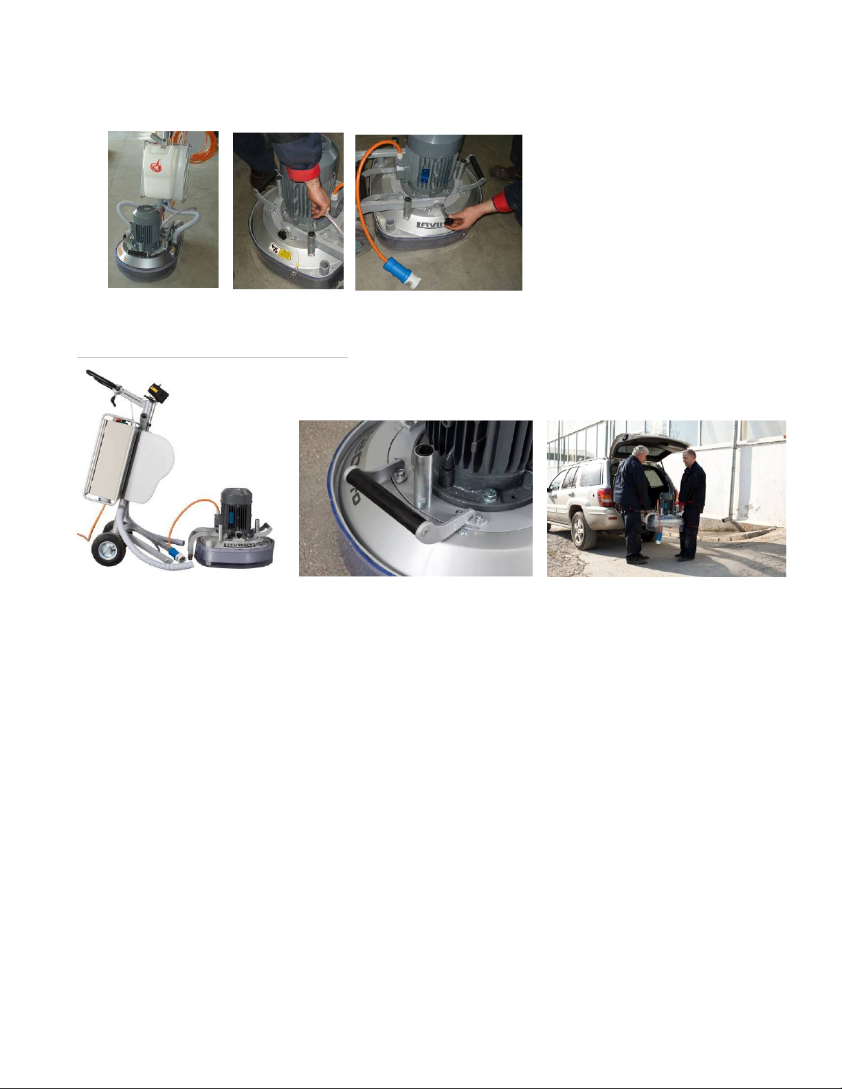
PREPARING THE MACHINE FOR TRANSPORTATION
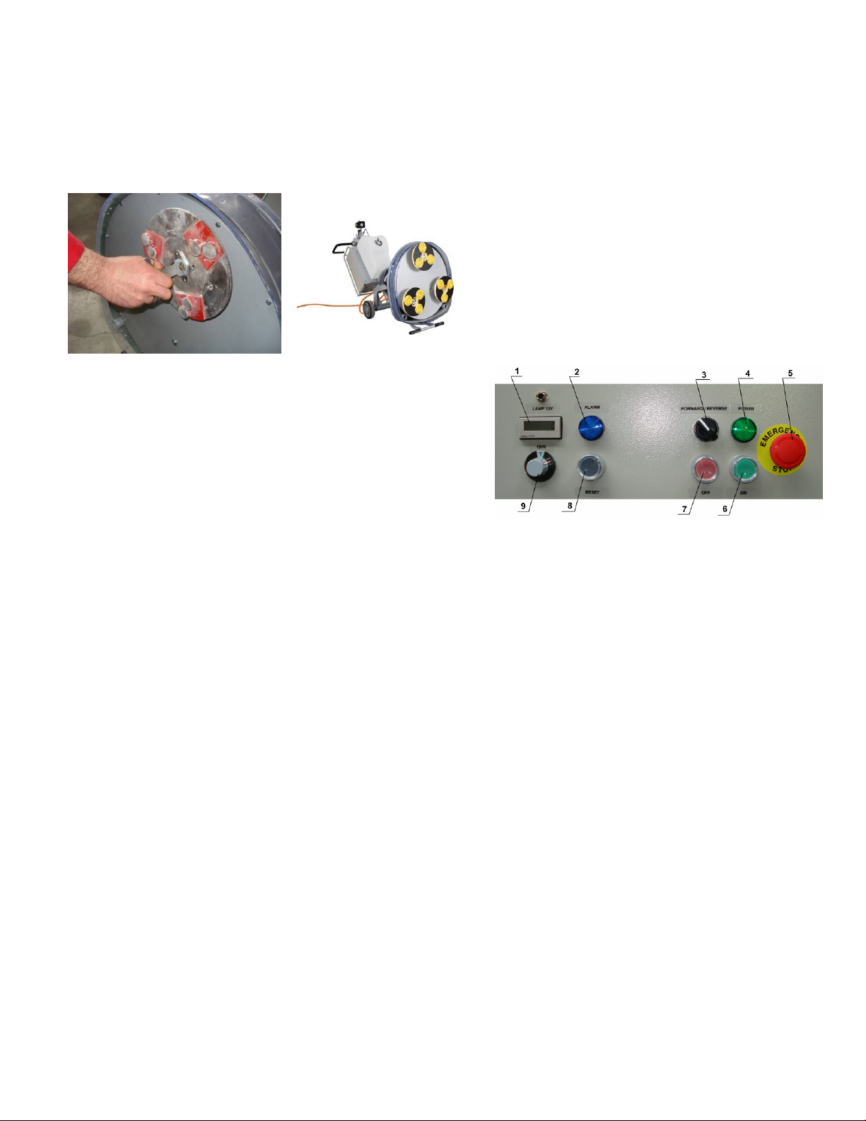
Unplug the motor cable plug from the control box (Fig. 3.1) and disconnect the water hose from the main head by
pulling it out (Fig. 3.2). Wind the electrical cable on the carriage. Release the pin sets (Fig. 3.3) which attach the head to
the carriage.
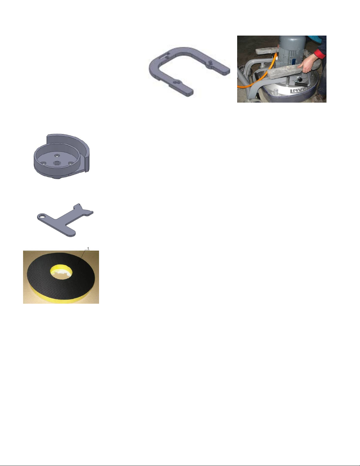
Pull out the vacuum hoses, and dismount the head from the carriage (Fig. 3.4).
The head of the Lavina 20®N Pro/20®NHV Pro has one bar and a support used as handles intended for easy moving
and transportation (Fig. 3.5).
The Lavina 20
allows convenient transportation and storage (Fig.3.4, Fig.3.6).
STORAGE
Always store and transport the Lavina 20®N Pro/20®NHV Pro in a dry place. Never transport the Lavina 20®N
Pro/20®NHV Pro unprotected; it may be damaged if transported unprotected during rain or snow.
Figure 3.1
Figure 3.4
Figure 3.2
Figure 3.5
®
Pro is engineered with easy transportation in mind. The ability to dismantle the machine in two parts
Figure 3.3
Figure 3.6
6
Superabrasive Owner’s Manual orginal language – Lavina 20®N Pro/20®NHV Pro 2/2012
4. OPERATION
PRELIMINARY CONTROLS
Inspect the working area as explained in the safety instructions. For wet use, fill in the water tank when the electrical
cable is disconnected. Connect the vacuum extractor and ensure that the vacuum hose is clear and it will follow the
machine easily. Plug in the machine and make sure that the power cord is free to follow the working direction of the
Lavina 20®N Pro/20®NHV Pro.
ADJUSTING AND MOUNTING TOOLS
Mount the tools only after ensuring that there is
enough diamond bond material left. Be sure
that the plates are always clean before
mounting. Always use the tool holder key
(Fig.4.1)
Diamond tools with Velcro are attached on
three foam plates of 9 inch. The foam plates
(Fig. 4.2) are mounted the same way as the
Figure 4.2
Figure 4.1
THE CONTROL BOARD
1. Digital RPM indicator
indicates the revolution per minute of the
grinding plates (not the revolution per
minute of the entire unit).
2. Inverter alarm led
lights blue when the inverter goes into
alarm mode.
3. Forward/Reverse switch
choose forward for clockwise rotation of
the grinding plates or reverse for anticlockwise rotation of the grinding plates
4. Power led lights green when the power is on
5. Emergency button used in Emergency situations for stopping the motor
6. ON button starts the motor
7. OFF button stops the motor
8. Reset button resets the alarm of the inverter
9. Potentiometer changes the RPM of the grinding plates from 300-1100 rpm
STARTING THE MACHINE
First, follow the directions in chapter Safety Devices and Safety Instructions. Next, pull the emergency stop (5) to
ensure that the machine is in working condition. Check the potentiometer (9) and ensure that it is set at the working
speed. If working wet, add water to the floor surface. If working dry, omit this step, and instead, switch on the vacuum
unit. Finally, hold the machine firmly and push the start button (6).
OPERATING THE MACHINE
Guide the machine in straight lines across the floor, and with each new line overlap a little bit of the previously
completed surface. Work at a constant speed allowing the tools time to work at a speed appropriate for the tools’ grit
size. Avoid vibrations. Do not stop the Lavina 20®N Pro/20®NHV Pro machine in one spot while the tools are still
working because they will leave marks on the floor surface. When working wet, open the water tank periodically to
release water onto the floor surface. When working dry, check the floor surface periodically to ensure that dust is not
accumulating on the surface, also check regularly if your vacuum works properly.
STOPPING THE MACHINE
The stopping of the machine must be done gradually until the motor stops. Do not stop moving the machine before
arresting the motor as the tools could damage the surface. To stop push the off button (7). Use the Emergency button
(5) only in emergency or use it to switch the power totally off.
Remember not to hold the machine in one spot before turning off the motor.
ALARM
The Alarm light (2) will light incase inverter goes in alarm mode. The most common failure is motor in overload. To reset
the mode push reset button (8).
other tools.
Figure 4.3
7
Superabrasive Owner’s Manual orginal language – Lavina 20®N Pro/20®NHV Pro 2/2012
5. TOOLS AND ACCESSORIES
WEIGHTS
Superabrasive offers additional weights
for increasing the productivity of the
machine (Fig.5.1). Each additional weight
weighs about 48 lbs or 22 kg. Each
individual application, type and condition
of surface, power capacity of the outlet,
etc. will determine the number of weights
you can use without tripping a breaker.
The weight stacks on to three posts
around the outer bowl (Fig.5.2).
The additional weights depend on the
tools; it is not always possible to add weights. Some tools work too aggressively and the
machine can stop. The weight can be ordered with item number A07.00.00.00
BELT REPLACING TOOL
You need the belt replacing (fig.5.3) tool when you want to replace the belt. It is explained
below in chapter Troubleshooting.
This tool can be ordered with number L20SPS-00.00.01.00
Figure 5.3
TOOL HOLDER KEY
The tool holder key (Fig. 5.4) is used for adjusting, mounting and dismounting of the tools.
Always use the key for mounting. Item number is A03.00.00.00
Figure 5.4
FOAM PLATE
Diamond tools with Velcro are mounted on the foam plate 9“(Fig.5.5). The foam plate is
mounted on the flexible backer plate. Item number is LV-9-FP
Figure 5.1
Figure 5.2
Figure 5.5
8
Superabrasive Owner’s Manual orginal language – Lavina 20®N Pro/20®NHV Pro 2/2012
6. POPULAR TOOLS
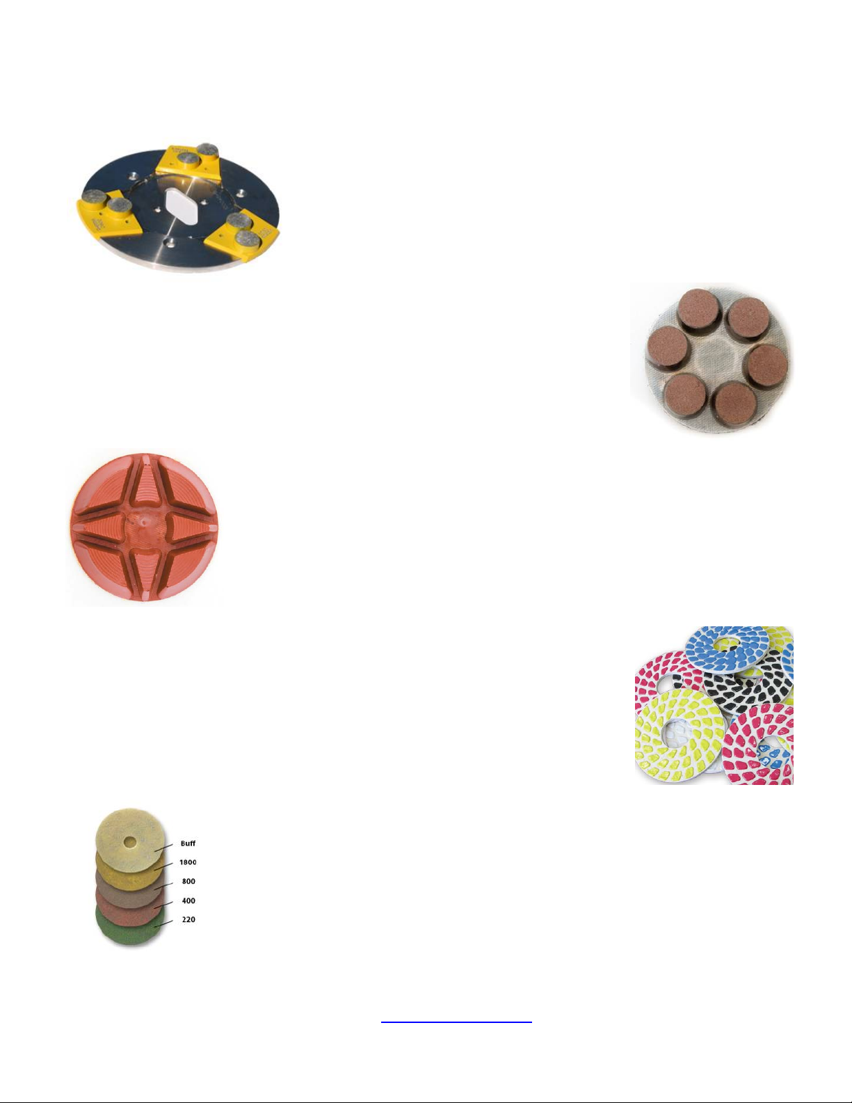
RECOMMENDED TOOLS
QuickChange Plates and Tooling feature extremely fast and convenient tool
changes, and a long tool life. The QuickChange plates are produced in several
sizes to accommodate any size
times, providing for great long-term cost savings. The QuickChange trapezoid
pads are produced in three different bonds for hard, medium and soft concrete, in
a variety of grit sizes, with either 1 or 2 buttons, which allows you to customize
the aggressiveness of the cut.
Calibra grinding discs: our popular ceramic bond discs are designed for the removal of
difficult scratches and they save you valuable time by eliminating the need for multiple
passes with metal tools. They can be used wet or dry, and are best for hard concrete
applications.
NATO® polishing discs feature a special resin formula designed for both wet and dry
applications and a unique design with wide channels allowing for work on a cleaner surface
and ensuring a quality polish. Available in 3 and 4 in sizes.
V-HARR® Premium Polishing Pads are
restoring concrete; also ideal for terrazzo and hard stone floors. V-HARR® pads are
offered in a wide variety of diameters and grit sizes to accommodate many applications.
Dry use is strongly recommended.
Diama-Clean pads are high quality diamond-impregnated pads for floor maintenance.
Available in a variety of sizes (17, 20, 21, 27 inch and other sizes), they are designed for use
under swing machines and burnishers, and are great for daily use – they require only water (no
wax or chemicals needed) and are a very environmentally friendly solution for maintaining
floors.
Use only Superabrasive’s recommended tools see www.superabrasive.com
designed for mechanically polishing and
LAVINA machine, and can be reused many
9

Superabrasive Owner’s Manual orginal language – Lavina 20®N Pro/20®NHV Pro 2/2012
7. MAINTENANCE AND INSPECTION
CLEANING
Keep your machine clean. Cleaning the machine on a regular basis will help detect and solve potential problems before
they cause damage to the machine. Most importantly, check and clean the tool plate connections, power cord and
plugs, vacuum hoses and water tank.
CHECK DAILY
After operating the Lavina 20®N Pro/20®NHV Pro, the operator should conduct a visual inspection of the machine. Any
defect should be solved immediately. Pay attention to power cords, plugs and vacuum hoses.
Shock absorbers A01/00.00.01 (See page Floating backer plate) are consumables and have to be checked daily and
replaced if needed. Buffers and spiders (See page SA tool holder and page SAM tool holder) are consumables and
must be visually checked daily and replaced if needed. The key lock holders on the tool holders should be also
checked.
CHECK EVERY 200 WORKING HOURS
Every 200 working hours, the operator should inspect all parts of the machine carefully. Most importantly, inspect and
clean the tool plate connections, power cord and plugs, vacuum hoses and water tank. Also, check the water flow.
Check the guard assembly. Make certain the wheels are clean and rotate properly. Inspect the control buttons. If there
are defective control parts, they should be replaced immediately. Replace worn vacuum- and water hoses.
Machines with floating backer plate tool holder (Fig. 12.3.1 and Fig. 12.13.1)
Dismount the seal assemblies (See Troubleshooting) replace all parts (pins, seal assemblies, “O” rings) with the
slightest damage or consume. Check the floating backer plates; replace sealer fronts, shock absorbers.
Machines with SA tool holder (Fig. 12.3.2 and Fig. 12.13.2) or with SAM tool holder (Fig. 12.3.3 and Fig. 12.13.3)
Dismount the tool holders (See Troubleshooting) replace all parts (Spider, buffers, sealer caps, “O” rings) with the
slightest damage or consume.
CHECK EVERY 400 WORKING HOURS
Besides the checks of 200 working hours, open up the bottom cover like described in chapter “TROUBLE SHOOTING
REPLACING BELT AND PULLEY UNITS. Check if sealers, belt and bearings are in good condition, change if needed.
VACUUM
As stated previously, frequently check hoses and other parts for clogging.
WATER LEAKS
Replace any leaking parts immediately as the water could damage your machine
MECHANICAL PARTS
Parts such as the belt, seal rings, cap rings, spiders and buffers and guard assembly are subject to wear and should be
replaced as needed.
ELECTRICAL SYSTEM
Dust should not enter the control box, as it will destroy the contacts. Remove (blow out) any dust present.
SINGLE PHASE OR THREE PHASE CONNECTION
Only Lavina 20®N Pro 208-240 Volt
The Lavina 20®N Pro 208-240 Volt will automatically detect if the connection is based on single (L1, L2) or three phase
(L1, L2, L3) 208-240 Volt. The operator does not have to switch the machine; only connect to two phases or three
phases. For convenience, the machine is delivered with 2 different receptacles and cables (see fig. 7.1), each is
marked. Please mount your own local plug, rated for 30 Amps on it. Notice, the yellow/green cable is the ground (never
attach this to a phase); grey, brown and black are phases, (see fig. 7.2 two phases and 7.3 three phases)
Figure 7.1
Figure 7.2
10
Figure 7.3

Superabrasive Owner’s Manual orginal language – Lavina 20®N Pro/20®NHV Pro 2/2012
LAVINA 20®N PRO ELECTRICAL SCHEMES WITH YASKAWA INVERTER
208-240 Volt
Figure 7.4
The motor is connected in “Delta” (triangle) 230 Volt,
reminder for the wire connection of the motor.
Figure 7.5
LAVINA 20®N PRO ELECTRICAL SCHEMES YASKAWA CONNECTION MAIN CIRCUIT TERMINALS
Figure 7.6
11
Superabrasive Owner’s Manual orginal language – Lavina 20®N Pro/20®NHV Pro 2/2012
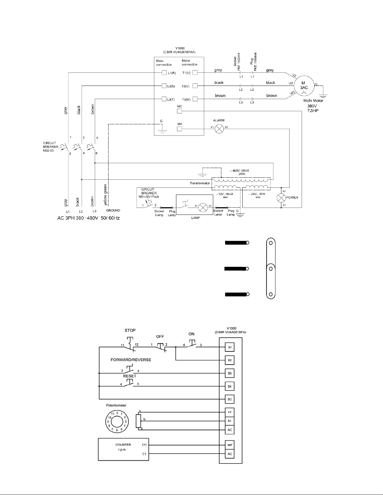
LAVINA 20®NHV PRO ELECTRICAL SCHEMES WITH YASKAWA INVERTER
380-480 Volt
Figure 7.7
The motor is connected in “Star” 380 Volt,
reminder for the wire connection of the motor.
Figure 7.8
LAVINA 20®NHV PRO ELECTRICAL SCHEMES YASKAWA CONNECTION MAIN CIRCUIT TERMINALS
Figure 7.9
12
 Loading...