

Page 1
Page 2

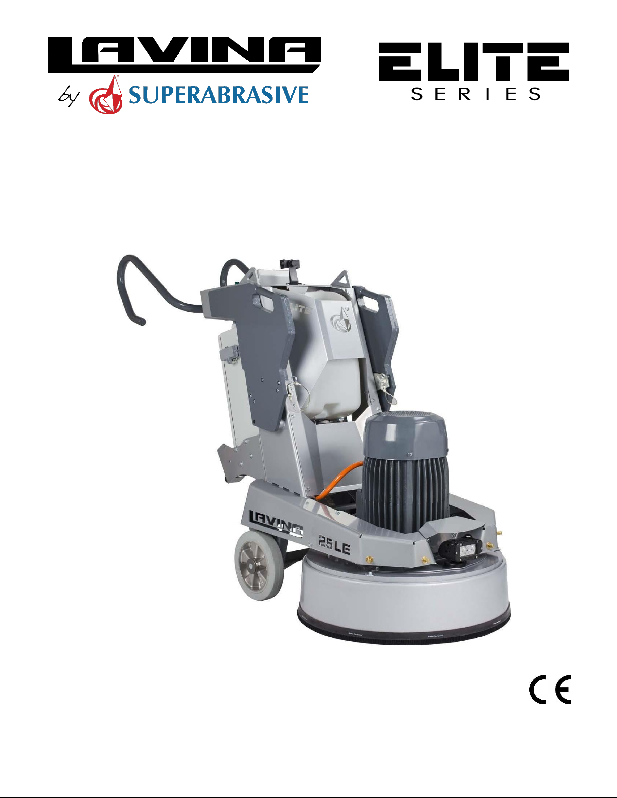
Superabrasive User Manual Original Language Lavina® 25LEU 5/2019
WARRANTY AND RETURNS
WARRANTY POLICY FOR LAVINA® ELITE MACHINES
A warranty card must be submitted to Superabrasive within 30 days of purchase in order for the foregoing warranty to apply.
You can either mail a hard copy of the warranty card or submit it electronically - see page 2.
Superabrasive warrants, from the time of delivery and receipt by the original customer, new and unused products sold by
Superabrasive or Superabrasive-appointed distributors or dealers. Goods shall be free from defects in materials and
workmanship. Superabrasive or a Superabrasive-appointed repair facility shall either replace or repair any defects in the
Goods resulting from faulty design, materials, or workmanship. Products repaired or replaced during the warranty period
shall be covered by the foregoing warranty for the remainder of the original warranty period, or ninety (90) days from date
of the repair or shipment of the replacement, whichever is longer. Spare parts for repair will be either new or equivalent to
new.
Warranty period shall be 2 years from the time of delivery and receipt by the original customer, or 600 operating hours on the
machine - whichever occurs first. Superabrasive will cover the shipping charges for the transportation of the machine to
Superabrasive (or an approved repair facility) and back to the customer (within the contiguous 48 United States) in the event
that the damage occurs and is reported within 200 operating hours. Shipping charges, if covered by Superabrasive, must be
agreed upon in advance and approved by Superabrasive. Thereafter, the customer will have to cover the shipping charges to
Superabrasive and back. Superabrasive will not warranty Goods after a period of 2 years from the time of delivery and receipt
by the original customer, or 600 operating hours on the machine - whichever occurs first.
Superabrasive shall not be liable for any defects that are caused by circumstances that occur after the Goods have been
delivered and whilst the Goods are in the possession of the purchaser. Furthermore, the warranty does not include normal
wear and tear or deterioration. Wear parts are not warranted. Superabrasive is not liable for defects arising out of use of
non-OEM parts.
The Warranty is void if the purchaser has not followed the maintenance plan stipulated by the machine’s manual and warranty
card. The warranty is void if the purchaser repairs said Goods himself, or if repairs are conducted by a repair facility that is not
approved by Superabrasive. Superabrasive’s liability does not cover defects which are caused by faulty maintenance, incorrect
operation, faulty repair by the purchaser, or by alterations conducted without Superabrasive’s prior written consent. The same
applies to any alterations of the Goods or services performed by another party other than Superabrasive, a Superabrasiveappointed distributor, or a Superabrasive-approved repair facility. The warranty is not applicable on a defect that arises due to
tools or parts that are not original to Superabrasive. Replaced defective parts shall be placed at Superabrasive’s disposal and
shall become property of Superabrasive. If such defective parts are replaced
within the warranty period, the shipping charges will be covered by Superabrasive. In warranty complaint cases, when no
defects are found for which Superabrasive is liable, Superabrasive shall be entitled to compensation for the labor, material cost,
and shipping charges, incurred by Superabrasive as as a result of the complaint.
The warranty herein is non-transferable, and only applies to the original owner or purchaser of the machine.
RETURN POLICY FOR LAVINA® ELITE MACHINES
The Lavina® ELITE machines may be returned, subject to the following terms:
In no case, a machine is to be returned to Superabrasive Inc. for credit or repair without prior authorization. Please contact
Superabrasive Inc. or your local distributor for an authorization and issuance of a return authorization number. This number
along with the serial number of the machine must be included on all packages and correspondence. Machines returned
without prior authorization will remain property of the sender and Superabrasive Inc. will not be responsible for them. No
machines will be credited after 90 days from the date of invoice.
All returns must be shipped freight prepaid. Returned machines may be exchanged for other equipment or parts of equal dollar
value. If machines are not exchanged, they are subject to a fifteen percent (15%) restocking fee.
2
Page 3

Superabrasive User Manual Original Language Lavina® 25LEU 5/2019
LAVINA ELITE L25LEU.................................................................. 1
1. GENERAL INFORMATION ................................................................. 4
1.1 MANUFACTURER........................................................................... 4
1.2 GENERAL DESCRIPTION ................................................................. 4
1.3 ENVIRONMENTAL CONDITIONS ..................................................... 4
1.4 VACUUM CONNECTION ................................................................. 4
1.5 LAVINA® 25LEU MAIN COMPONENTS ............................................ 4
1.6 TECHNICAL DATA .......................................................................... 6
1.7 VIBRATIONS .................................................................................. 6
1.8 CE-CERTIFICATION ......................................................................... 6
2. SAFETY INSTRUCTIONS .................................................................... 7
RECOMMENDED USE .......................................................................... 7
PROHIBITED USE ........................................................................... 7
PREPARATION FOR WORK .................................................................. 7
PROTECTION DEVICES .................................................................... 7
ARREST FUNCTIONS ...................................................................... 7
SAFE USE ..................................................................................... 7
RESIDUAL RISKS ........................................................................... 7
BEFORE YOU BEGIN ...................................................................... 7
OPERATING MACHINE ................................................................... 7
AFTER WORK IS COMPLETED ............................................................... 7
THE WORK AREA ..................................................................... 8
PERSONAL PROTECTIVE ................................................................ 8
EQUIPMENT (PPE) ............................................................................... 8
OPERATOR .......................................................................................... 8
3. HANDLING AND TRANSPORTATION ..................................................... 8
3.1 ADJUSTING THE HANDLE ............................................................... 8
3.2 TURNING THE MACHINE FROM WORKING TO TOOL MOUNTING
POSITION ............................................................................................ 9
3.3 LIFTING ......................................................................................... 9
3.4 STORAGE ...................................................................................... 9
4. OPERATION ......................................................................................... 9
4.1 PRELIMINARY CONTROLS .............................................................. 9
4.2 WATER FLOW CONTROL SYSTEM ................................................. 10
4.3 ADJUSTING AND MOUNTING TOOLS ........................................... 11
4.4 VACUUM CONNECTION ............................................................... 11
4.5 CONTROL BOARD ........................................................................ 12
4.6 STARTING THE MACHINE ............................................................. 12
4.7 OPERATING THE MACHINE .......................................................... 12
4.8 STOPPING THE MACHINE ............................................................ 13
5. TOOLS AND ACCESSORIES ............................................................. 13
TOOL HOLDER KEY ............................................................................ 13
SECURITY PLATE FOR QUICKCHANGE PADS ....................................... 13
6. POPULAR TOOLS ........................................................................... 14
7. MAINTENANCE AND INSPECTION .................................................. 15
CLEANING ......................................................................................... 15
CHECK DAILY .................................................................................... 15
......................................................................................................... 15
CHECK EVERY 200 WORKING HOURS ................................................. 15
CHECK EVERY 400 WORKING HOURS ................................................. 15
VACUUM .......................................................................................... 15
WATER LEAKS ................................................................................... 15
MECHANICAL PARTS ......................................................................... 15
ELECTRICAL SYSTEM .......................................................................... 16
LAVINA® 25LEU ELECTRICAL SCHEMES WITH YASKAWA INVERTER .... 16
LAVINA® 25LEU ELECTRICAL SCHEMES YASKAWA CONNECTION MAIN
CIRCUIT TERMINALS .......................................................................... 17
8. TROUBLESHOOTING ...................................................................... 18
INDEX OF PROBLEMS AND SOLUTIONS .............................................. 18
8.1 SEPARATING THE HEAD FROM THE CARRIAGE ............................. 18
8.2 DISMOUNTING/MOUNTING THE GUARD ..................................... 20
8.3 REPLACING POWER CORD AND PLUGS ......................................... 20
8.4 DISMOUNTING AND MOUNTING TOOL HOLDER TO CHANGING V-
RINGS AND FELT-RINGS ..................................................................... 20
8.5 DISASSEMBLING AND MOUNTING TOOL HOLDER TO CHANGE
BUFFERS AND ELASTIC ELEMENT ....................................................... 21
8.6 CORRECTING DEFLECTION OF THE USED PLANETARY CHAIN ......... 22
MOUNTING NEW PLANETARY CHAIN ............................................... 22
8.7 REPLACING THE PLANETARY DRIVING CHAIN WHEEL AND
PLANETARY TENSIONER .................................................................... 23
8.8 TENSIONING AND REPLACING THE BELTS ..................................... 24
......................................................................................................... 24
8.9 REPLACING THE DRIVEN PLANETARY GEAR (SPROCKET) ............... 26
8.10 REPLACING THE PULLEY UNITS ................................................... 26
8.11 REPLACING THE PLANETARY UNIT .............................................. 27
8.12 MOTOR CONNECTION ............................................................... 27
8.13 FAULT DIAGNOSIS INVERTER YASKAWA V1000 .......................... 28
9. DISPOSAL ...................................................................................... 30
10. MANUFACTURER’S CONTACTS ..................................................... 30
11. SPARE PARTS ............................................................................... 31
ASSEMBLY AND PARTS SPECIFICATIONS ............................................ 31
......................................................................................................... 31
1. LAVINA®25LEU GENERAL PARTS ................................................... 31
2. LAVINA® 25LEU BUMPER ............................................................. 31
3. LAVINA® 25LEU TOP COVER 1 PARTS ............................................ 32
4. LAVINA®25LEU GARD ASSEMBLY ................................................. 32
5. LAVINA®25LEU TOP COVER ASSEMBLY ......................................... 32
6. LAVINA® 25LEU BOTTOM COVER 1 PARTS ..................................... 33
7. LAVINA® 25LEU PLANETARY DRIVE PARTS .................................... 34
7.1. LAVINA® 25LEU PULLEY UNIT ASSEMBLY .................................. 35
8. LAVINA® 25LEU BOTTOM COVER 2 PARTS ..................................... 35
9. LAVINA®25LE TOOL HOLDER PARTS/SEE ALSO FIG.8.7.13/ ........... 36
(POS.1 INCLUDE POS.1.1;1.2;1.3/POS.1.3 INCLUDE POS.1.3.1 AND ETC.)
......................................................................................................... 36
10. LAVINA® 25LEU CARRIAGE PARTS 1............................................ 36
11. LAVINA® 25LEU CARRIAGE PARTS 2............................................ 37
12. LAVINA® 25LEU CARRIAGE PARTS 3............................................ 37
13. LAVINA® 25LEU WATER TANK ................................................... 38
14. LAVINA® 25LEU WATER BALL VALVE ........................................... 38
15. LAVINA® 25LEU WATER PUMP REGULATOR .............................. 38
16. LAVINA® 25LEU WATER PUMP .................................................. 39
17. LAVINA® 25LEU WATER INSTALLATION ..................................... 39
18 CONTROL BOARD ASSEMBLY ........................................................ 40
3
Page 4

Superabrasive User Manual Original Language Lavina® 25LEU 5/2019
1. GENERAL INFORMATION
This owner’s manual is intended for the operator of the Lavina® ELITE machine, the servicing technician as well as for anyone
involved with operating or servicing the machine. We recommend that you read the instructions very carefully and follow them
strictly. The manual includes information about assembling, using, handling, adjusting and maintaining your Lavina® ELITE floor
grinding and polishing machine.
1.1 MANUFACTURER
Superabrasive was founded in 1987, as a manufacturer of high quality diamond tools for the stone and concrete industry. Today,
Superabrasive is one of the world’s leading companies in the production of diamond tools and floor grinding machinery. At
Superabrasive, we strive to deliver the very best solutions to our customers, and enable them to work more efficiently.
1.2 GENERAL DESCRIPTION
The Lavina® ELITE machine is intended for grinding, polishing and buffing concrete, marble, granite, limestone and terrazzo
surfaces with diamond tools. Additionally, the machine could be used for grinding wood floor surfaces.
The Lavina® ELITE machine is a three-disc machine, which can be used wet or dry.
For best results, use only tools manufactured or recommended by Superabrasive and its distributors.
The Lavina® ELITE machine is manufactured and fitted for the above-mentioned applications only! Every other use may possess
risks to the persons involved.
1.3 ENVIRONMENTAL CONDITIONS
The temperature range for operating the Lavina® ELITE machine outdoors is between 41°F and 86°F or 5°C and 30°C. Never
use
the
Lavina® ELITE machine during rain or snow when working outdoors. When working indoors, always operate the
machine in
1.4 VACUUM CONNECTION
A connection for a vacuum dust extractor is located on the carriage. The Lavina® ELITE machine does not include a vacuum dust
extractor. The customer must purchase the vacuum dust extractor separately. The vacuum dust extractor must be adapted for
floor grinders and have a minimum air displacement of 310m3/h with a negative vacuum of 21 kPa.
1.5 LAVINA® 25LEU MAIN COMPONENTS
The Lavina® ELITE machine is made of two main component sections:
well‐
ventilated
1.5.1 Carriage which contains:
Handle - the handle on the frame is adjustable in height and allows the operator to work in a correct and safe
posture (see point 3. Handling and transportation).
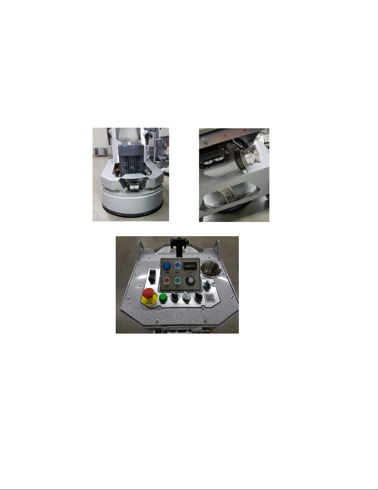
LED lights - the LED lights (Fig.1.1; Fig.1.2) enables the operator to work in darker
does not replace adequate overhead
The control panel (fig.1.3) is positioned on top of the frame and contains
machine also for the pump, lights, RPMs control switch, hour meter unit, EMG button and the USB port for
charging your phone.
The water tank is on the opposite side of the frame, so that the weight of
operation of the machine. The frame weight, on
electric pump sprays
Power box
Water pump
areas.
areas.
Existing lighting system
lighting.
the
water through a front mist system or
buttons and switches for start/stop the
the
water does not affect the
the
other hand, is fully absorbed by the driving wheels. An
internal under cover.
4
Page 5
Superabrasive User Manual Original Language Lavina® 25LEU 5/2019
Figure 1.1
Figure 1.2
Figure 1.3
1.5.2 Machine head which contains:
The Electric motor - its mounted on the base plate
The planetary motion - it derives from the main engine, driven by a simplex roller chain
The self‐leveling Guard is designed to have contact with the surface. Anytime,
the tool
used.
“Quickchange” tool holder is designed to hold the tools with
and
it is driving the three heads with a belt
no
matter the height of
“Quickchange”connection (All of our new tools
system.
.
use the “Quickchange” connection and there is no more foam holders).
5
Page 6

Superabrasive User Manual Original Language Lavina® 25LEU 5/2019
Lavina® 25LEU
Voltage/Hz
3 ph x 380-400V 50-60Hz
Amperage
Max 30 Amps
Power
11 kW
15 HP
Tool holder rpm
300-1100 rpm
Working width
655 mm
25.8”
Tool diameter (QC Plate)
3x 225 mm
3x 9”
Weight
380 kg
838 lbs
Grinding pressure
Weights upward
201 kg
443 lbs
Grinding pressure
Weights downward
237 kg
522 lbs
Application
wet and dry
Vacuum hose port
Cam lock E250
Water tank capacity
20 l
5.2 gal
Water feed
Peripheral and front mist with pump
Cable length
17.4 m
57 ft
Machine LxWxH
1430x617x1214 mm
56x24.3x47.8”
Packing LxWxH Crate 1
1480x840x1454 mm
58.3x33x57.2”
1.6 TECHNICAL DATA
1.7 VIBRATIONS
The vibrations of the machine are within the limits of directives and harmonized standards from the European Union when
Lavina® ELITE is operated with the recommended tools and in normal
SONOROUS
EMISSIONS
conditions
.
The sonorous emissions are within the limits of directives and harmonized standards from the European Union when the
Lavina®
must wear
LABEL
The data on the label provides the correct Voltage and kW (needed for operational
Weight (needed for transportation purposes); production year and serial number (needed for maintenance
CUSTOMER
ELITE is operated with the recommended tools and in normal conditions. However, as previously stated, the operator
ear protectors.
DATA
SERVICE
purposes);
purposes).
For customer assistance and technical support call your local distributor or call Superabrasive Inc. at
1‐800‐987‐8403 or visit us at: www.superabrasive.com , where you can download a copy of this
manual
.
1.8 CE-CERTIFICATION
The Lavina® ELITE machine is designed to operate correctly in an electromagnetic atmosphere of industrial type and is
equipped with all the mechanical and electrical safety protections in conformity with the following European CEE rules and
regulations:
The Lavina® ELITE machine complies with the Safety Directive for machines 2006/42/EC, the EMC Directive 2004/108/EC and
the Low Voltage Directive 2006/95/EC.
Also complies with the norms in use BDS EN ISO 12100, BDS EN 13862,BDS EN ISO 13857, BDS EN 349, BDS EN ISO 13850,BDS
EN 13732-1, BDS EN 953, BDS EN ISO 13849-1,BDS EN 1037, BDS EN ISO 5349-1, BDS EN ISO 11201, BDS EN ISO 3744, BDS EN
1033:2002, BDS EN 60204-1,BDS EN 1837, BDS EN 61000-6-4, BDS EN 61000-6-2, BDS EN 61000-4-2, BDS EN 61000-4-4, BDS EN
61000-4-5,BDS EN 61000-4-11, BDS EN 55016-2-1
Test results are a part of the machine’s technical information and can be sent upon a special request. The machine is delivered
with the CE mark exposed and provided with a EC declaration of conformity.
6
the
Page 7
Superabrasive User Manual Original Language Lavina® 25LEU 5/2019
2. SAFETY INSTRUCTIONS
Recommended Use
The Lavina® E machine is designed and manufactured to grind and
polish concrete, terrazzo, and natural stone floors. It can be used
for renovation as well as for polishing. The machine is designed for
dry or wet use. When using it dry, use a vacuum of appropriate size.
For more information, please refer to the chapter on handling the
vacuum connection.
Prohibited Use
The machine MUST NOT be used:
For applications different from the ones stated in the general
description chapter.
For non-suitable materials. In environments which:
- Possess risks of explosion,
- Possess high concentration of powders or oil substances in the
air,
- Possess risks of fire Feature inclement conditions,
- Possess electromagnetic radiation.
PREPARATION FOR WORK
Make sure that:
You have closed the work area, so that no person unfamiliar with
operating the machine can enter the area.
The tool plate and tools are adjusted to the machine properly.
There are no missing parts of the machine
The machine is in upright working position.
The protection devices are working properly.
The electrical cable is free to move and follow the machine
easily.
In order to keep the electrical cable from being damaged, no
vehicle should cross the zone where electrical cables are
situated.
PROTECTION DEVICES
The machine is equipped with
several protection devices
including the following:
• An emergency stop button
• A protection skirt and a hood for protecting the tool plates.
These devices protect the operator and/or others persons from
potential injuries. Do not remove them. Before using the machine,
please ensure that all protection devices are mounted and function
properly. The Security plate prevents the QuickChange
pads to from loosening during work
Arrest Functions
Methods of arresting of the machine are following:
• Button to stop the motor (category 1)
• Emergency button (category 1)
Safe Use
The Lavina® E is designed to reduce risks correlated with its use.
However, it is not possible to fully eliminate the risks of an accident
with the machine. An unskilled or uninstructed operator may cause
correlated residual risks. Such risks are:
• Position Risks: due to operator’s incorrect working position
• Entanglement Risks: due to wearing inappropriate
working clothes
• Training Risks: due to lack of operational training.
• NOTE: In order to reduce any consequences of the
above‐ mentioned risks, we advise that machine operators
follow the instructions in the manual at all times.
Residual Risks
During the normal operating and maintenance cycles, the operator
is exposed to some residual risks, which cannot be eliminated due
to the nature of the operations.
Before You Begin
Working area must be clear from any debris or objects.
A first‐time operator must always read the manual and pay
attention to all safety instructions.
All electric connections and cables must be inspected for
potential damages.
Ground wire system of the power supply must be also
inspected.
Perform general daily inspections of the machine and inspect
the machine before each use.
Always inspect the safety devices: Mount the Security plate
for the QuickChange pads.
The emergency break must be clear and working
The tool protector must be working
The machine must be clean Never operate the machine in
the rain!
Confirm that there are no missing parts especially after
transportation, repair or maintenance.
• Before filling the water tank with water make sure the
machine is not working and the main switch is turned off.
• Before turning on the machine make sure that the base is
placed on the floor, the machine MUST NOT be in an upright
position when turned on!
Operating Machine
When operating the Lavina® E, make certain that there is no one
but you around the machine.
Never leave the machine unattended while working. The
electrical cable must move freely and must be damage‐ free.
The water hose must move freely and must be damage‐free.
Check to make sure the floor you are preparing to work on is
even. If the floor is uneven, it may damage the machine.
AFTER WORK IS COMPLETED
• Clean the machine and its surroundings properly
• Empty and clean the water tank
7
Page 8
Superabrasive User Manual Original Language Lavina® 25LEU 5/2019
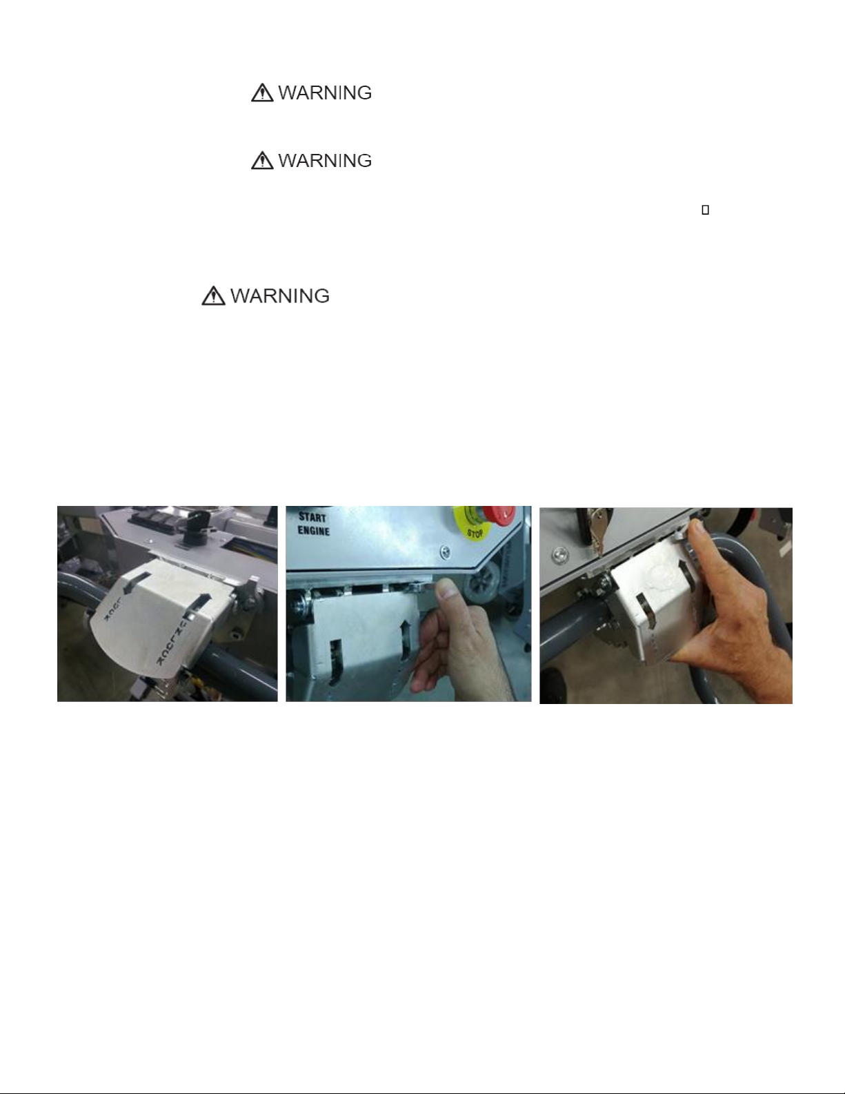
Figure 3.2
Figure 3.3
Figure 3.4
• Unplug the machine and wind up the electrical cable
• Store the machine in a safe place
The Work Area
• Ensure that people or vehicles do not enter the work area.
• Clear any cables or hoses from the work area.
• Always check the floor for debris.
Personal Protective
Equipment (PPE)
• Always wear safety shoes when working with the machine.
• Always wear ear protectors when working with the machine.
• All personnel in the immediate work area must wear safety
glasses with side shields.
• Always wear safety gloves when changing the tools.
• Always wear clothes suitable for the work environment.
The operator must know the machine’s work environment.
Only one operator can work with the machine at a time. The
operator must be properly trained and well‐instructed prior
operating the machine.
• The operator must understand all the instructions in this
manual.
• The operator must understand and be able to interpret all
the drawings and designs in manual.
• The operator must know all sanitation and safety regulations
pertaining to the operation of the machine The operator
must have floor grinding experience.
• The operator must know what to do in case of emergency.
• The operator must have adequate technical knowledge and
preparation.
OPERATOR
3. HANDLING AND TRANSPORTATION
3.1 ADJUSTING THE HANDLE
The Handle on the frame is adjustable in height and allows the operator to work in a correct and safe posture (Fig. 3.1, Fig.
3.2, Fig. 3.3, and Fig.3.5). Choose the upright position to move easy the machine.
8
Page 9

Superabrasive User Manual Original Language Lavina® 25LEU 5/2019
Figure 3.7
Figure 3.5
Figure 3.6
3.2 TURNING THE MACHINE FROM WORKING TO TOOL MOUNTING POSITION
Put the handles of the carriage as shown on (Fig. 3.5). Ensure that the
water tank is empty
in position shown on (Fig.
before
flipping the machine. Push the handles and flip
3.6).
If necessary, help by placing your foot on
the heel near the control box.
3.3 LIFTING
Lifting the machine by crane is possible by using the handles of the carriage (see fig. 3.5 and fig. 3.6).Do not lift any other loads
on the machine. Always use
hoisting
equipment rated for 350 kg (772
lbs) or greater.
3.4 STORAGE
Always store the LAVINA® ELITE machine in a dry place.
Never transport
be damaged if transported
snow.
When the machine is in storage and the temperature may fall
down to or below 32F (or 0o C). You should empty the water
from the system:
- Pull out the hose of the tank (Fig.3.7)
- With compressed air blow out the water from the
system in the two positions of the turn-cock.
the
LAVINA® ELITE machine unprotected; it may
unprotected
and exposed to rain or
4. OPERATION
4.1 PRELIMINARY CONTROLS
Inspect the working area as explained in the safety instructions. Fill in the water tank for wet use or connect the vacuum extractor
and ensure that the vacuum hose is clear and it will follow the machine easily.
Make sure that the electrical motor is connected with the power box and then you can connect the power cable with the electricity
and start the machine.
9
Page 10
Superabrasive User Manual Original Language Lavina® 25LEU 5/2019
Figure 4.1
Figure 4.2
Figure 4.3
Figure 4.4
Figure 4.5
Figure 4.6
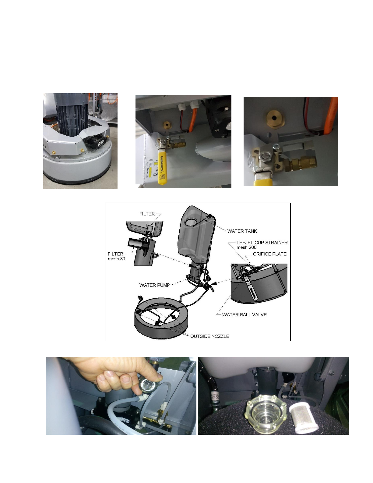
4.2 WATER FLOW CONTROL SYSTEM
The operator can direct water to be sprayed in front of the machine (Fig.4.1) by positioning the lever in the horizontal
position (Fig.4.2). Water will spray under the cover of the machine when the lever is in the vertical position (Fig.4.2). The
pressure regulator is located above the lever (Fig.4.3) and controls the water pressure in the system. You can see the
whole water flow control system - main and filtering parts in fig4.4. Fig. 4.5 and fig. 4.6 shows how to remove and clean
the filter mesh. In the instances where more water is required to spray under the cover of the machine, the orifice plate
(shown on pos.8 of table 14 in „spare pats“ ) can be removed.
ALWAYS USE CLEAN WATER TO PROTECT THE SYSTEM FROM DIRT
10
Page 11
Superabrasive User Manual Original Language Lavina® 25LEU 5/2019
Figure 4.7
Figure 4.8
Figure 4.6
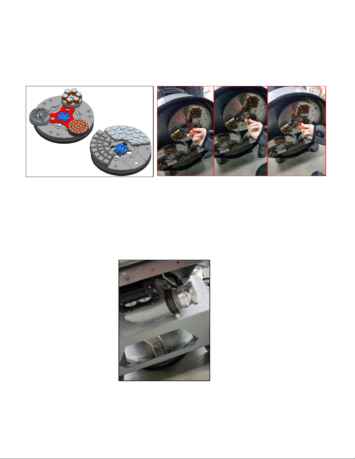
4.3 ADJUSTING AND MOUNTING TOOLS
Lavina® 25LEU uses tool holder A63. With this new holder every one of our tools uses the “Quickchange” connection. To change the
tools you need first to unlock the butterfly (fig 4.6 in blue) by using the key we provide you (you can see it in the pictures fig. 4.7)
remove the security plate (fig 4.6 in red) then load the tools you want and insert the security plate again so the tools cannot go
backwards, rotate and lock the butterfly (as shown in fig.4.7). As you can see in fig. 4.6, for some of the new tools you need to
remove the security plate as they don’t need locking system at all but for the others always make sure that the tools are securely
locked.
1
In Lavina 25LEU the holder is initially mounted with 3 buffers.
Mount the tools only after ensuring that there is
before mounting.
WARNING: Always secure the Quick Change tools with the butterfly (Fig.4.6 in blue), lock with the tool holder key
(Fig.4.7) and make sure that the butterfly is securely locked and it holds the security plate not to fall off.
enough
diamond bond material left. Be sure that the plates
2
are
always clean
3
4.4 VACUUM CONNECTION
To connect a vacuum cleaner, the Lavina 25LE is supplied with vacuum hose Cam Lock inlet C250 / vacuum hose diam. 2, 5 in
(63mm)
(Fig.4.8).
11
Page 12
Superabrasive User Manual Original Language Lavina® 25LEU 5/2019
Figure 4.9
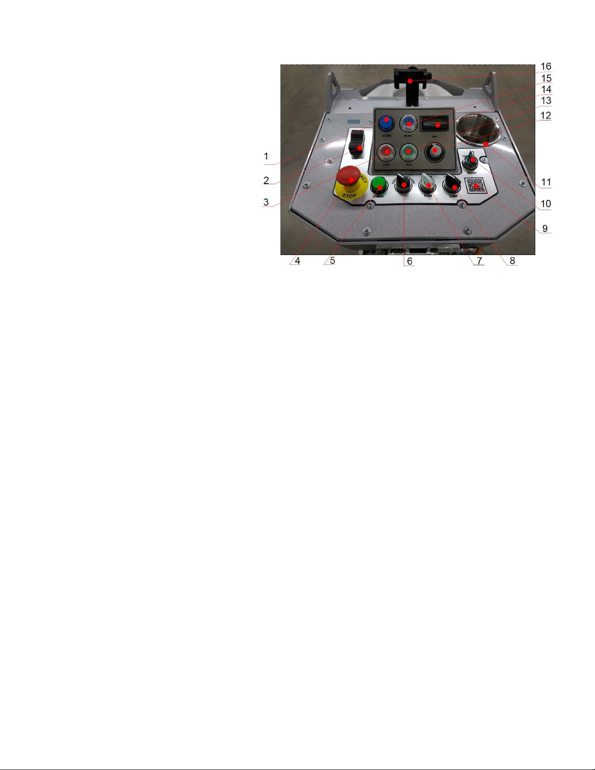
4.5 CONTROL BOARD
1. ALARM glowing button. Usually glows when
you pressed the EMG button.
2. USB charger.
3. STOP button which stops the motor.
4. EMERGENCY button used to stop the motor in
case of emergency.
5. POWER glowing button - it glows when the
machine is connected to the electricity.
6. Forward/Reverse switch. Select forward for
clockwise rotation of the grinding plates or reverse
for counterclockwise rotation of the grinding plates
(recommended configuration). The preferred
operating direction should be when the switch is in
the forward position. The proper direction of
rotation of the motor (counterclockwise) is indicated
by an arrow on its cover.
7. Water pump switch. Glows in orange when the
water pump is working.
8. LED lights switch
9. QR code. When you scan it with your phone for example, it will redirect your browser to Lavina manuals page.
10. READY ON / OFF switch. If you want to start the motor it must be ON as it puts the inventor into standby mode (it glows
when it’s turned ON). If it’s off the inventor will be out of standby mode and you cannot start the motor. The switch
returns to its starting position after being released.
11. Cup holder.
12. Potentiometer. Controls the RPM of the grinding plates in a range of 300-1100 rpm.
13. RUN button. Start the motor (ready ON/OFF switch must be ON).
14. Digital Tachometer. Indicates the revolution per minute of the grinding plates (not the revolution per minute of the entire
unit).
15. Reset button. Resets the alarm of the inverter.
16. Phone holder.
4.6 STARTING THE MACHINE
First, follow the directions in the chapter on Safety Devices and Safety Instructions. Next, release the emergency stop (4), turn the
Ready switch (10) to the ON position to put the machine in standby mode. Check the potentiometer (12), and ensure that it is set to
the working speed. If you are working wet, add water to the floor surface by starting the pump (7). If you are working dry make sure
your machine is connected to the vacuum unit. Finally, hold the machine firmly and push the RUN button (13).
4.7 OPERATING THE MACHINE
Guide the machine in straight lines across the floor, slightly overlapping the previously completed surface with each new
line. Work at a constant speed, allowing the tools time to work at a speed appropriate for the tools’ grit size. Avoid
vibrations. Do not stop the machine while tools are still running as they will mark the surface of the floor. When working
wet, select the destination of the water feed with the water tap (fig. 4.2) and periodically run the pump to release water
onto the floor surface. Starting the pump is possible only if the machine motor is on. When working dry, check the floor
surface periodically for dust accumulation. Check regularly to see if you’re vacuum works properly.
12
Page 13

Superabrasive User Manual Original Language Lavina® 25LEU 5/2019
Figure 5.1
Figure 5.2
4.8 STOPPING THE MACHINE
The stopping of the machine must be done gradually until the motor stops. Do not stop moving the machine before the motor comes
to rest, as the tools could damage the surface.
To stop the machine:
1.Push the STOP button (3) .
2.Turn the ON/OFF (10) switch in position OFF, this will cut the voltage to the invertor and the green light will turn off.
5. TOOLS AND ACCESSORIES
TOOL HOLDER KEY
The tool holder key (Fig. 5.1) is used for adjusting, mounting and dismounting of
the foam plates. Always use the key for mounting.
Item number is A03.00.00.00
SECURITY PLATE FOR QUICKCHANGE PADS
Plate (Fig.5.2) used to ensure the “Quickchange” tools.
Item number is A63.00.01
13
Page 14
Superabrasive User Manual Original Language Lavina® 25LEU 5/2019
6. POPULAR TOOLS
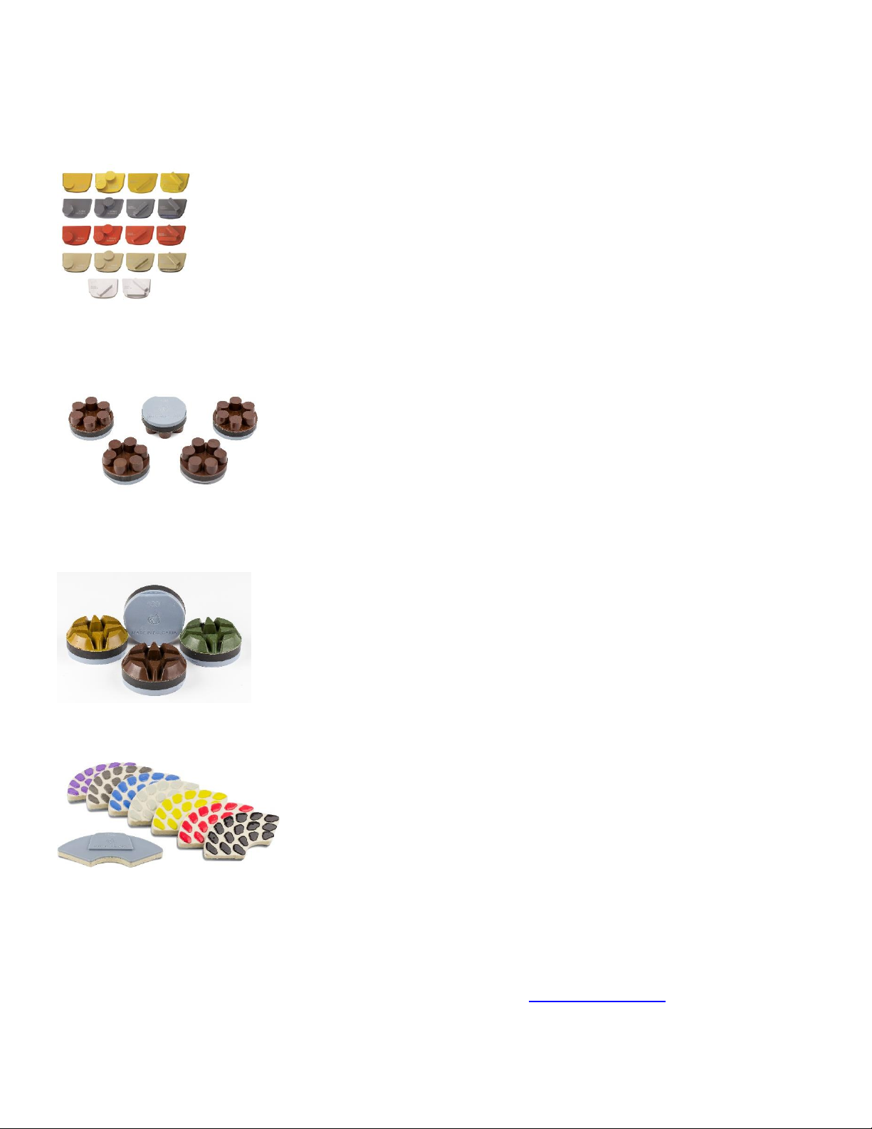
QuickChange System and Tooling feature extremely fast and convenient tool changes, and a long tool life,
providing for great long‐term cost savings. The QuickChange pads are produced in four different bonds for super
hard, hard, medium and soft concrete, in a variety of grit sizes. They are offered with 1 or 2 buttons or rectangular
segments, which allows you to customize the aggressiveness of the cut.
CORSA HYBRID DISCS WITH QUICK CHANGE ATTACHMENT (WET OR DRY) : The new Corsa hybrid
discs are designed for scratch removal and transitioning from metal to resin tools, and are similar
to Calibra but the ceramic bond has been modified for more efficient use on soft and medium
concrete.
NATO® WITH QUICK CHANGE ATTACHMENT
Superabrasive's Nato resin pucks are a great tool choice for soft and hard concrete polishing
applications. Among the thickest diamond pads on the market - featuring a thick 12mm layer of resin
and diamonds for extra long life. Wide channels and a unique patented design allow for work on a
cleaner surface, ensuring a quality polish. Offered in wet and dry bond.
V‐HARR® Premium Polishing Pads for 9-inch TOOL HOLDERS
NOW AVAILABLE IN A QUICK CHANGE STYLE - NO FOAM PLATES NEEDED
V-Harr felt diamond pads are one of Superabrasive’s most versatile and successful diamond tools
for concrete polishing. V-Harr pads are also ideal for polishing terrazzo and hard stone floors. V-
Harr polishing pads should be used DRY on concrete! However, they will produce remarkable
gloss results on black granite when used wet.
Use Only Superabrasive’s Recommended Tools. For More Tooling Options, Visit www.superabrasive.com
14
Page 15
Superabrasive User Manual Original Language Lavina® 25LEU 5/2019
Figure 7.1
Figure 7.2
Figure 7.3
7. MAINTENANCE AND INSPECTION
CLEANING
Keep your machine clean. Cleaning the machine on a regular basis will help detect and solve potential problems before they can cause
damage to the machine. Most importantly, check and clean the tool plate connections, power cords, plugs, vacuum hoses, and water
tank.
CHECK DAILY
After operating the Lavina®E machine, the operator should conduct a visual inspection of the
machine. Any defect should be solved immediately. Pay attention to power cords, plugs, vacuum
hoses, loose bolts or screws.
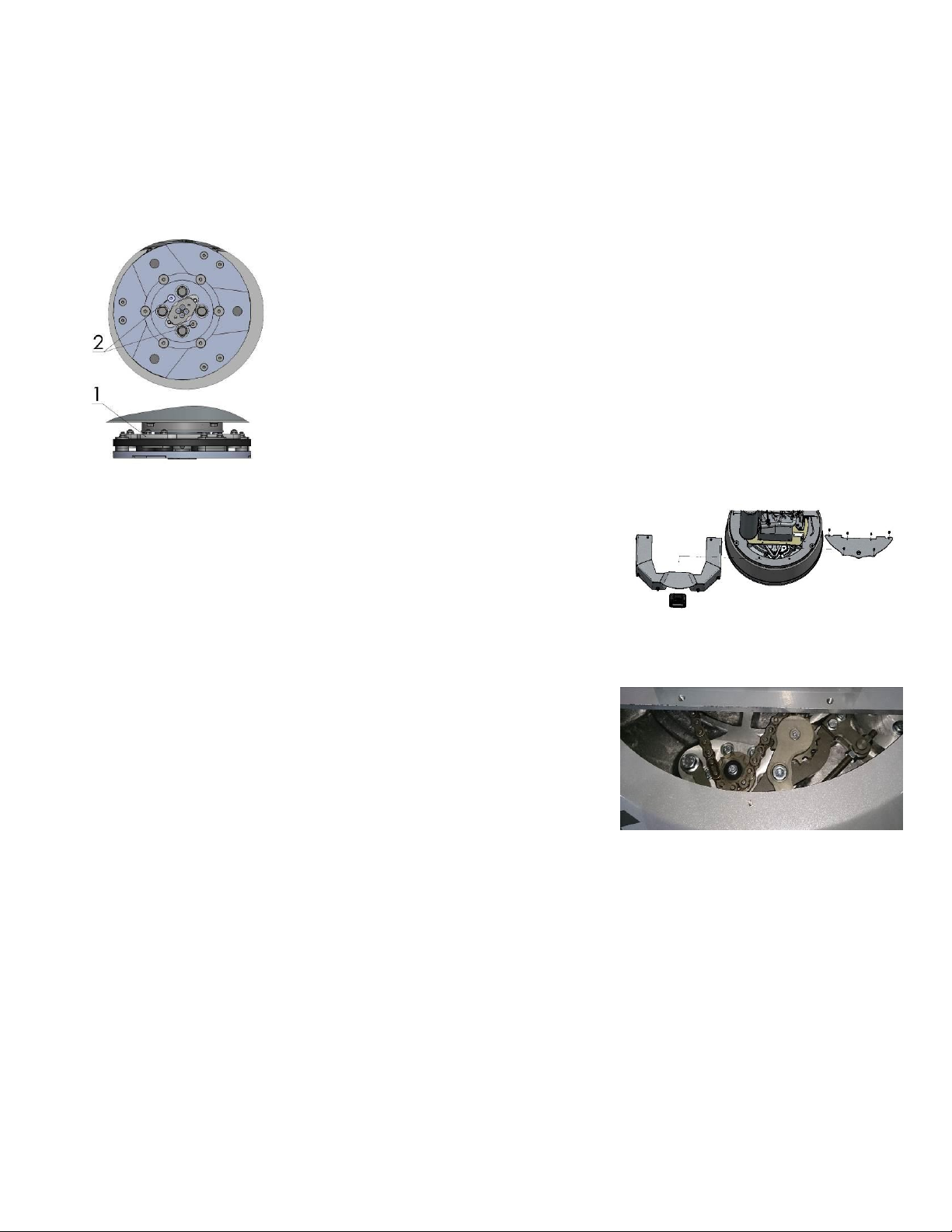
Tool holders: Buffers and elastic element are consumables and must be visually checked on a daily
basis and replaced if necessary. Make sure the flanges or discs are securely locked in place. The key
lock holders (butterflies) should also be checked.
Check the rubber buffers and make sure the holders are secure. The flange holding the buffers
(Fig.7.1‐1) has to be firmly secured to the unit. If there is a gap seen here, that means the screws
securing the holder are loose. The screws have to be tightened immediately to safely operate the
machine. Working with loose screws could cause serious damage to the machine. The tightening force
of the screws has to be 22‐25N.m (16‐18ft∙lbf).
It is very important to regularly check the screws that secure the “QuickChange” holder to the
7.1
“QuickChange” should also be cleaned.
.
CHECK EVERY 200 WORKING HOURS
Every 200 working hours, the operator should inspect all parts of the machine
carefully. Most importantly, inspect and clean the tool plate connections, power
cord plugs, vacuum hoses and water tank/filter. Also, check the water flow of the
pump. Check the guard assembly. Ensure the wheels are clean and rotate properly.
Inspect the control
buttons. If there are defective control parts, they should be replaced immediately.
Replace any worn vacuum or water hoses.
Open the service cover on the motor base (Fig 7.2) (Fig 7.3) to check the
planetary chain. Lubricate the chain with chain lubricant and correct the sag if
needed. (For sagging correction see TROUBLESHOOTING 8.4)
Dismount the tool holders (See TROUBLESHOOTING) and replace any parts
(elastic element, buffers, sealer caps, “O” rings) showing any damage.
CHECK EVERY 400 WORKING HOURS
In addition to checks made every 200 working hours, replace sealer and V‐rings as described in chapter “TROUBLESHOOTING ‐
DISMOUNTING TOOL HOLDERS TO CHANGING V‐RINGS AND FELT‐RINGS.
VACUUM
As stated previously, frequently check hoses and othe r parts for clogging.
WATER LEAKS
Replace any leaking parts immediately as the water could damage your machine
.
MECHANICAL PARTS
Parts such as the belts, seal rings, cap rings, spiders and buffers and guard assembly are subject to wear and should be replaced
as needed.
safety part (Fig.7.1‐ 2), so that the holder will not fly away if the buffers get damaged. The
Figure
15
Page 16
Superabrasive User Manual Original Language Lavina® 25LEU 5/2019
OPERATION
INTERVAL
Daily
Every 200
Hrs.
Every 400
Hrs.
Inspect power cords, plugs and vacuum hoses, loose bolt or
screws.
X
Check the rubber buffers, elastic element and fixing of the
holders
X
Inspect and clean the tool plate connections
X
Inspect and clean water tank, filters mesh and misting nozzle
X X
Inspect the seal rings and bearings of the grinding units
X
Check the planetary chain and lubricate
X X
Replace Felt-Ring and V‐rings
X
Check belts and bearings
X
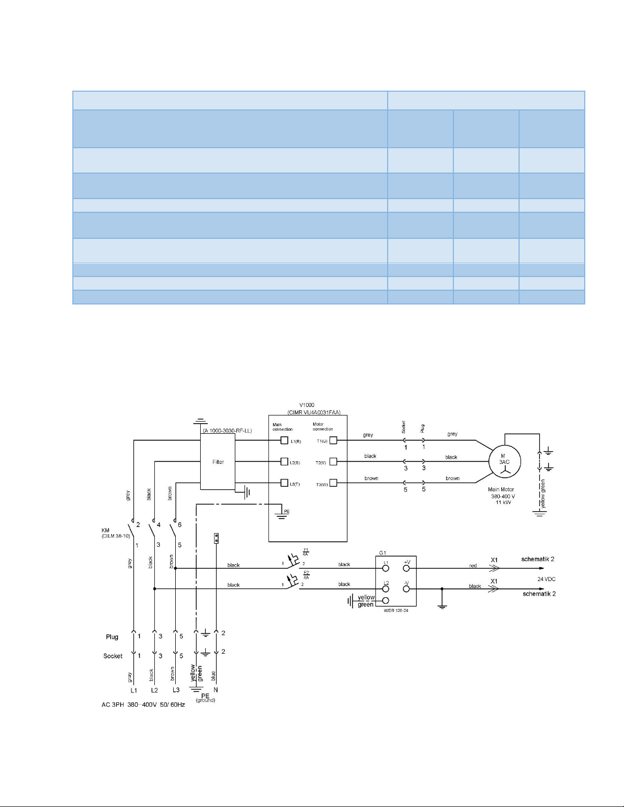
Figure 7.4 /scheme 1/
ELECTRICAL SYSTEM
Dust should not enter the control box, as it will destroy the controls. Remove (blow out) any dust present.
LAVINA® 25LEU ELECTRICAL SCHEMES WITH YASKAWA INVERTER
380-400 Volt
16
Page 17
Superabrasive User Manual Original Language Lavina® 25LEU 5/2019
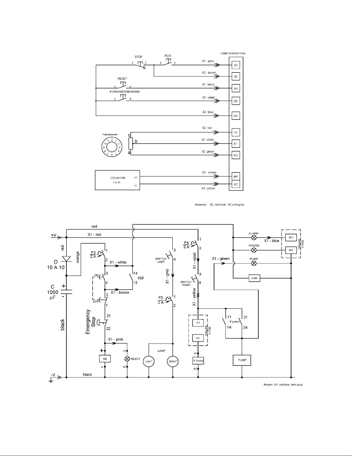
Figure 7.6 /scheme 2/
Figure 7.6 /scheme 3/
LAVINA® 25LEU ELECTRICAL SCHEMES YASKAWA CONNECTION MAIN CIRCUIT TERMINALS
17
Page 18
Superabrasive User Manual Original Language Lavina® 25LEU 5/2019
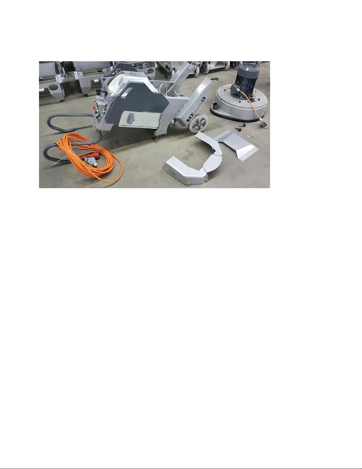
Figure 8.1
8. TROUBLESHOOTING
INDEX OF PROBLEMS AND SOLUTIONS
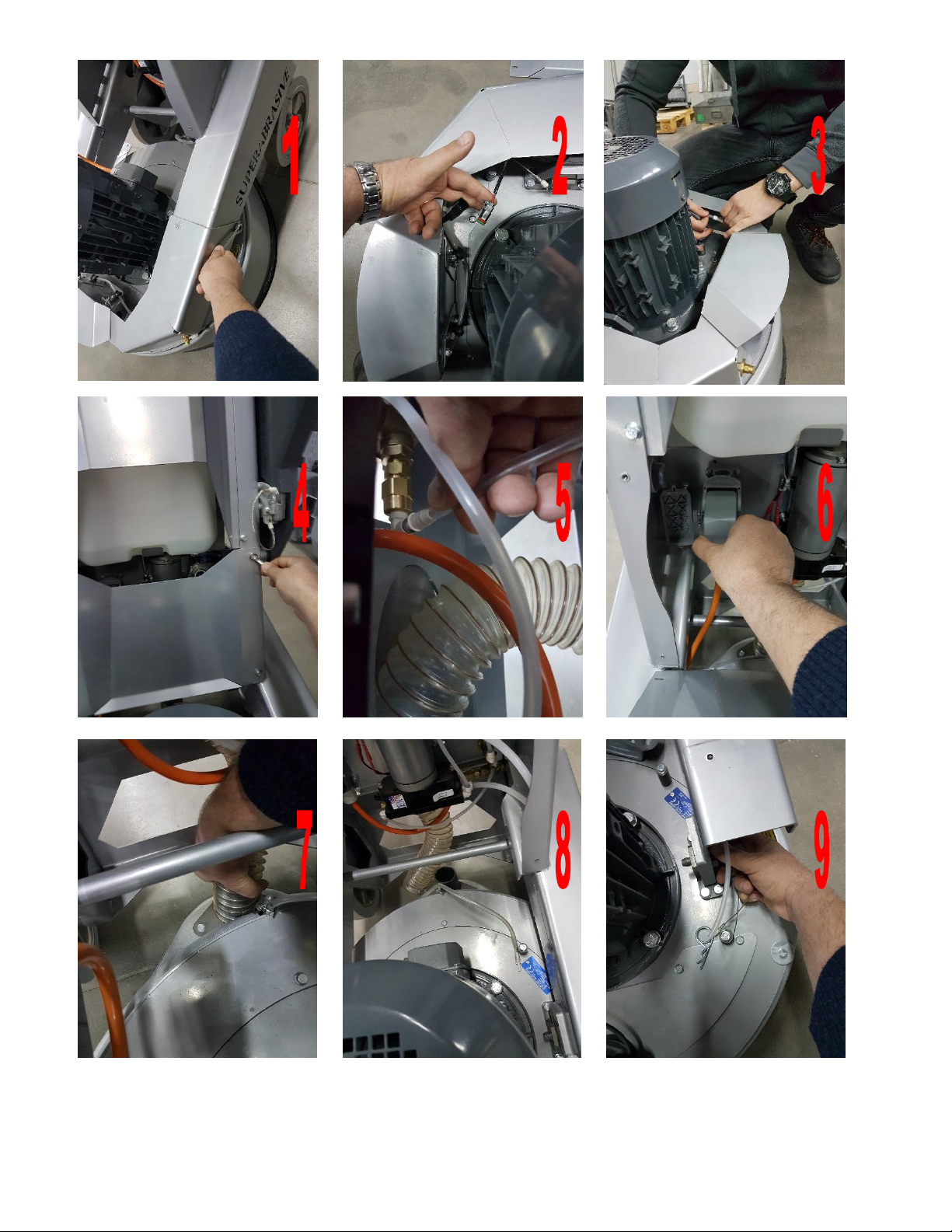
8.1 SEPARATING THE HEAD FROM THE CARRIAGE
1. Unscrew the four bolts to remove the panel fig. 8.2-1.
2. Disconnect the cable of lamp and remove the lamp fig. 8.2-3.
3. Disconnect the flexible hose under the panel fig. 8.2-2. All water connections in the machines are with fitting types
“Push-in” and “Release button”.
4. Unscrew the four bolts to remove the cover fig. 8.2-4.
5. Disconnect the flexible hose which comes from the pump fig. 8.2-5.
6. Disconnect the engine cable from the power box fig. 8.2-6.
7. Release the clamp and remove the suction hose from the head fig. 8.2-7.
8. Make sure everything is disconnected fig. 8.2-8.
9. For separating the carriage from the head you need to be two people – one to hold the carriage while the other
removes the pins fig 8.2-9. After the pins are removed the person which is holding the carriage should carefully place it
on the ground without harming it fig. 8.1.
18
Page 19
Superabrasive User Manual Original Language Lavina® 25LEU 5/2019
Figure 8.2
19
Page 20
Superabrasive User Manual Original Language Lavina® 25LEU 5/2019
Figure 8.4.1
Figure 8.4.2
Figure 8.4.3
Figure 8.4.4
Figure 8.4.5
Figure 8.4.6
Figure 8.4.7
Figure 8.4.8
Figure 8.3
Figure 8.4
8.2 DISMOUNTING/MOUNTING THE GUARD
You can dismount and mount the safe guard
without separating the carriage from the
main head. Put the machine in position to
change the tools. Unscrew the four bolts M5
from the metal cover preventing the safe
guard to fall. Dismount one of the three
holders. Dismount the safe guard.
8.3 REPLACING POWER CORD AND PLUGS
When replacing the power cord or plugs, always use cords and plugs with the same specifications as the original ones. Do
not use lower quality or different types of cords or plugs.
In addition, consider the distance between the appliance and the electrical source. The greater the distance, the greater the resistance and
the less current that will be available at the other end. This will cause a voltage drop and the inverter will switch into alarm mode. This will
also happen if several machines are working on the same line or the generator is not rated for the power needed. In general, our standard
power cable can be doubled in length; longer lengths require replacing all the cables with cables of a larger gauge rate to account for the
length and amperage.
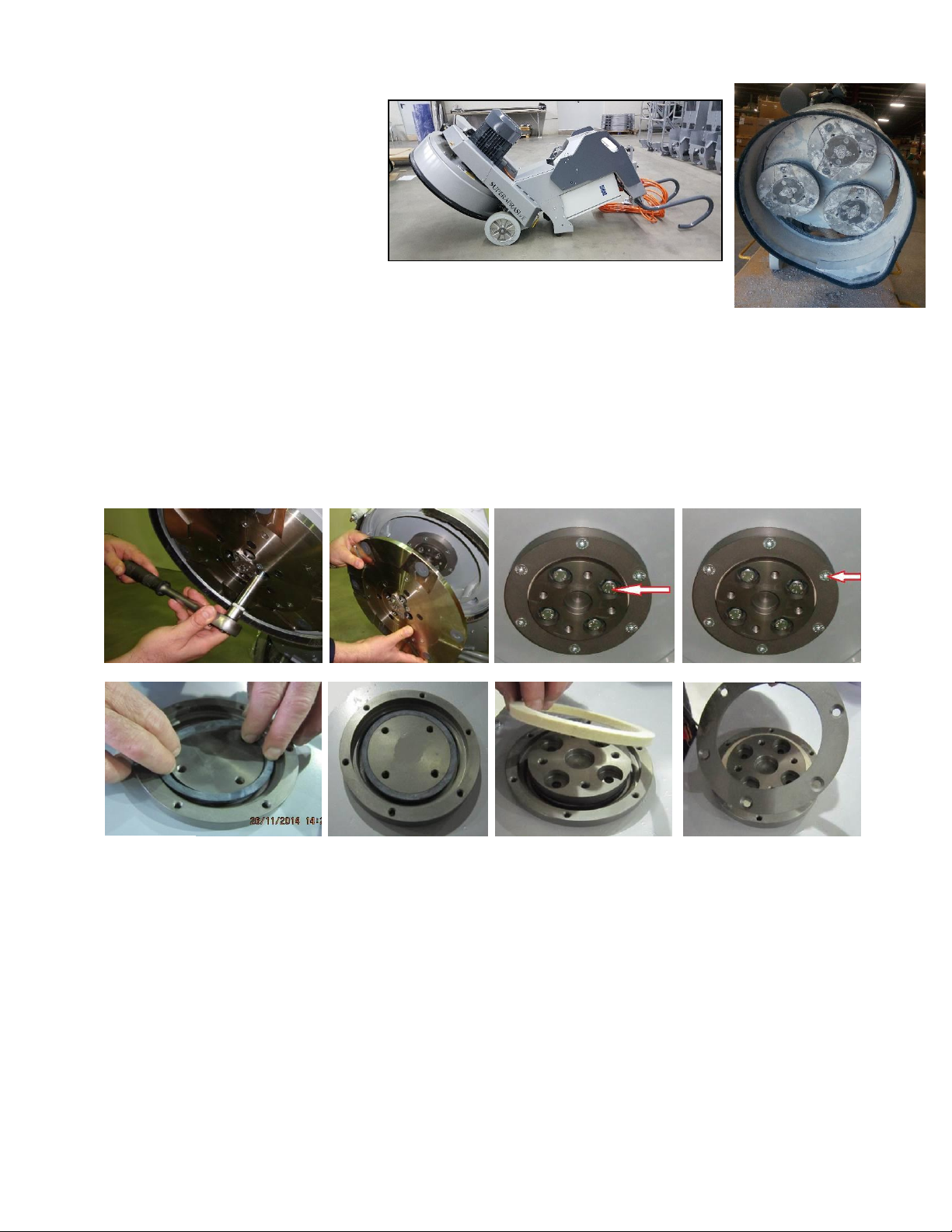
8.4 DISMOUNTING AND MOUNTING TOOL HOLDER TO CHANGING V-RINGS AND FELT-RINGS
To check or replace the buffers and the elastic elements, the tool holders have to be dismounted.
You will need a 13mm deep metric socket with an outside diameter of no more than 3/4in to unscrew the four bolts (Fig.8.4.1) and remove
the holder (Fig.8.4.2). When the tool holder is dismounted, you can change the sealers (V‐Ring and Felt‐Ring).
By loosening four Hex cap flange bolts (Fig.8.4.3) the adaptor comes loose. Unscrew the six screws of the cap (Fig.8.4.4) holding the felt‐
ring. Take out the Felt‐Ring, adaptor and V‐Ring.
Mount the V‐Ring with the smallest lip of the V to the inside (Fig.8.4.5) ‐ simply push the V‐Ring so the top is on the same level as the
pulley top (Fig.8.2.6). Then take the adaptor and push the V‐Ring down with the adaptor (Fig.8.4.7). The lowest lip of the V‐Ring should only
barely touch its gliding surface. Mount the adaptor and the Felt‐Ring on top (Fig.8.4.7). Close the sealers with the cap (Fig.8.4.8) and screw
the bolts. Always use the original bolts. Do not push the V‐ring down with fingers.
20
Page 21
Superabrasive User Manual Original Language Lavina® 25LEU 5/2019
Figure 8.5.10
Figure 8.5.11
T
C
Figure 8.5.12
Figure 8.5.13
Figure 8.5.5
Figure 8.5.1
Figure 8.5.2
Figure 8.5.7
Figure 8.5.3
Figure 8.5.4
Figure 8.5.8
Figure 8.5.9
Figure 8.5.6
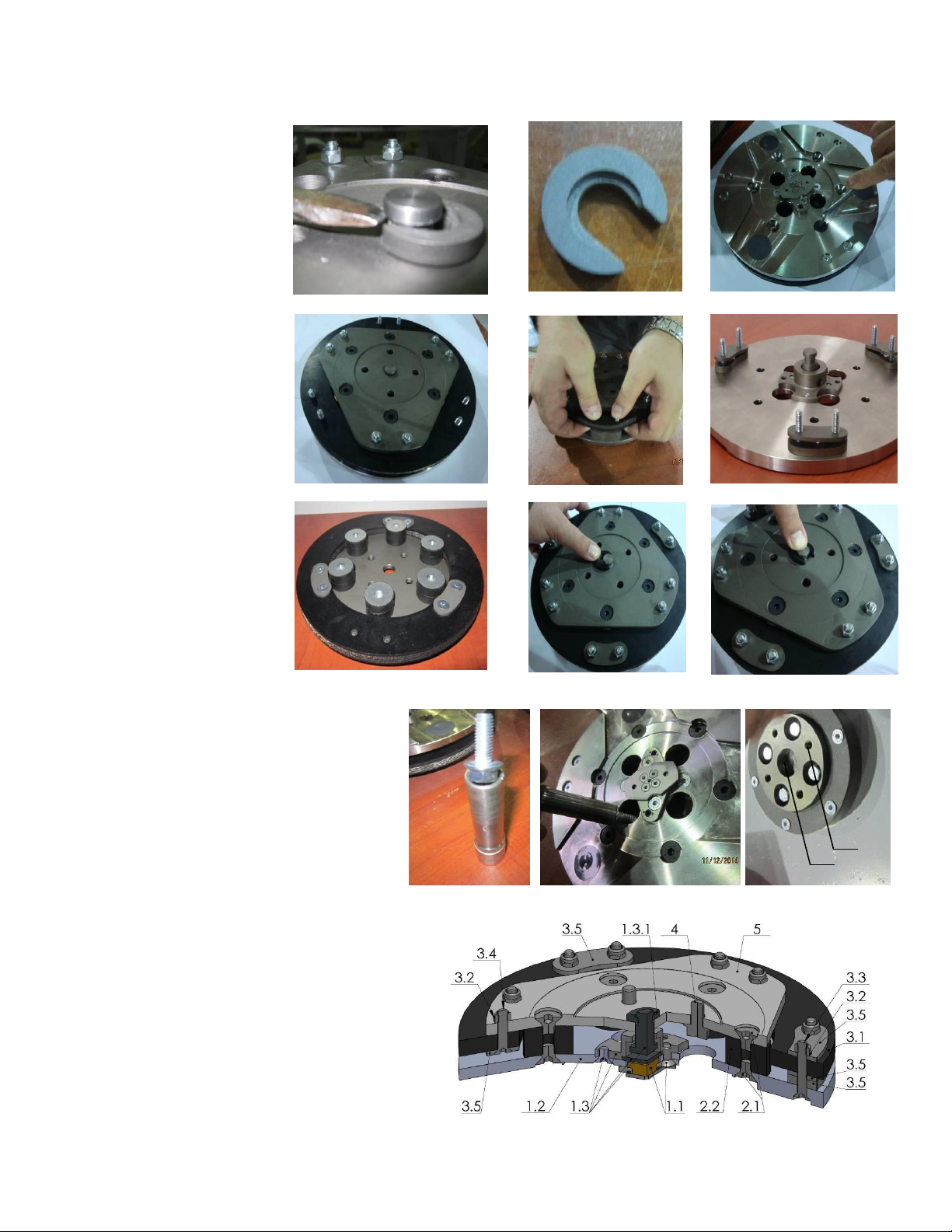
8.5 DISASSEMBLING AND MOUNTING TOOL HOLDER TO CHANGE BUFFERS AND ELASTIC ELEMENT
When the TOOL HOLDER is
disassembled you can change
defective parts – elastic element,
buffers, etc.
Lift the locking pin (Fig.8.5.1) to
dismount the retaining washer
(Fig.8.5.2). Take out the screws on
the buffers and the nuts of the
elastic element (Fig.8.5.3;Fig.8.5.4).
Remove the elastic element from
the QC plate (Fig.8.5.5). While the
holder is dismounted
(Fig.8.5.6;Fig.8.5.7), clean the parts
and replace any defective ones with
new ones. Assemble the holder
with new buffers, new screws, and
new elastic element. Replace the
retaining washer (Fig.8.5.8) and
push the locking pin (Fig.8.5.9). This
will prevent the washer from falling
while mounting the holder on the
machine.
Make sure the four bolts holding
the adaptor (Fig.8.5.12) are
reliably tighten. Mount the
holder on the machine using the
same socket as mentioned in 8.2
(Fig.8.5.10;Fig.8.5.11). The
retaining washer fits into the
central hole C of adaptor and the four bolts into the
thread holes Т (Fig.8.5.12). The holder is centered
on the outside diameter of the adaptor. Ensure the
holder is properly connected to the plate of the
adaptor and then tight evenly the four
bolts.Tightening force of the bolts has to be
22...25N.m(16...18 ft/lbs). Mounting the holder
without retaining washer (Fig.8.5.2) is
INADMISSIBLE because the security system
preventing the separation of part of the holder in
case of broken buffers and elastic element will not
function!You can change the butterfly of the holder
without dismounting the holder of the machine.
You can change the butterfly of the holder without
dismounting the holder of the machine. Fig.8.5.13 is a 3‐
D section view of the holder, showing its parts. The
numbering is the same as in Spare parts.
21
Page 22
Superabrasive User Manual Original Language Lavina® 25LEU 5/2019
Figure 8.6.2
Figure 8.6.1
Figure 8.6.3
Figure 8.6.4
Figure 8.6.5
Figure 8.6.1
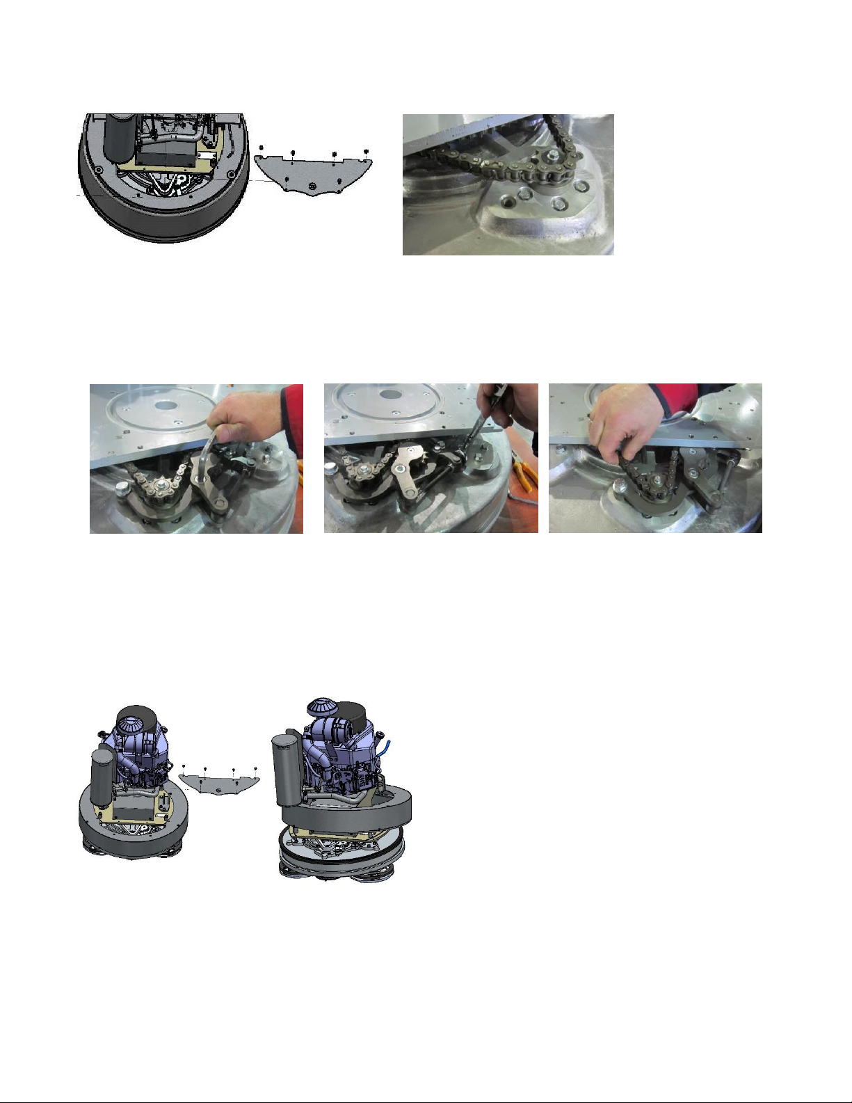
8.6 CORRECTING DEFLECTION OF THE USED PLANETARY CHAIN
Unscrew the bolts and take out the cover (Fig.8.6.1). Lift the machine in position to change the tools. Turn manually the holders in
order to turn the main head, stop when you see through the window the chain tensioner (Fig.8.6.2).
Loosen a quarter to 1/2 rev the
two bolts of the chain tensioner
(Fig.8.6.3) the tensioner should
turn with minimum clearence,
without inclination, then
unscrew the inner nut. To
tension the chain screw the
outer nut (Fig.8.6.4). The tensioner of the planetary chain should allow chain sagging 3...5mm/1/8...3/16 in/ controlled in span X
(Fig.8.6.5). When ready screw the two nuts (Fig.8.6.4) and the screw(Fig.8.6.3).
ATTENTION: NEVER “OVER” TENSION THE CHAIN, THE CHAIN WILL BE DAMAGED
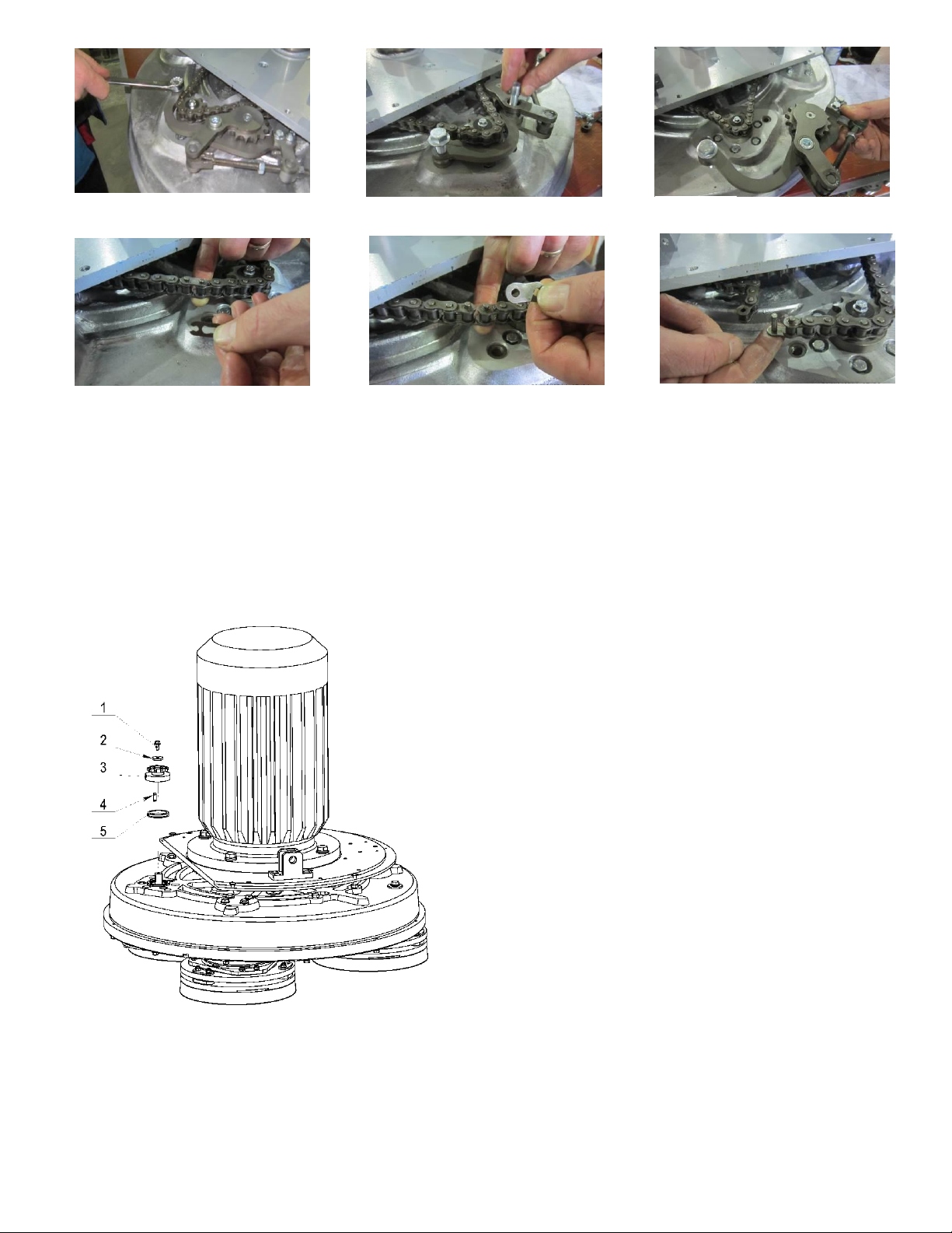
MOUNTING NEW PLANETARY CHAIN
The planetary chain is replaced with new one when the step/drive of the chain tensioner is finished or there is a break in the
integrity of the chain. Unscrew the bolts (Fig.8.6.1) and take out the cover. Lift the machine in position to change the tools.
Turn manually the holders in order to turn the main head, stop when you see through the window the chain tensioner
(Fig.8.6.2). Separate the carriage from main head, point 8.4 , pull out motor plug, water tubes and vacuum tubes. Take off handle
(without water tubes). Release the pin sets which attach the head to the carriage. Take off the service window (Fig. 8.6.1) so you
can dismount the top cover
Loosen the two nuts(Fig.8.6.4) and uscrew the two screws of the
tensioner (Fig.8.6.8)(Fig.8.6.9)(Fig.8.6.10). Take the chain
tensioner(Fig.8.6.11). Pull out the split pin (Fig.8.6.12) and the
chain link pin (Fig.8.9.8) (Fig.8.6.13). Take the chain, and put on
the same way the new chain, get in the chain link pin and the split
pin (Fig.8.6.13) (Fig.8.6.12) (Fig.8.6.11).
22
Page 23
Superabrasive User Manual Original Language Lavina® 25LEU 5/2019
Figure 8.6.11
Figure 8.6.12
Figure 8.6.13
Figure 8.6.10
Figure 8.6.9
Figure 8.6.8
Figure 8.7.1
Mount the chain tensioner (Fig.8.6.10). Tighten the two screws (Fig.8.6.8)(Fig.8.6.9). Loosen the bolt of the chain tensioner a quarter to a
half revolution (Fig.8.6.9). The tensioner should turn with minimum clearance, without inclination. Then unscrew the inner nut. To
tension the chain, rotate the outer nut (Fig.8.6.4) . The tension of the planetary chain should allow chain sagging of 3...5mm (1/8...3/16
in) measured in span X (Fig.8.6.5).
When properly tensioned, retighten the two nuts (Fig.8.6.4) and the screw(Fig.8.6.9).
ATTENTION: NEVER “OVER” TENSION THE CHAIN, THE CHAIN WILL BE DAMAGED
8.7 REPLACING THE PLANETARY DRIVING CHAIN WHEEL AND PLANETARY TENSIONER
Check and repeat the instructions in 8.5 MOUNTING NEW
PLANETARY CHAIN.
Unscrew bolt (1) and remove the chain pulley (3) with the sealer (5).
Change the sealer, and mount it to the chain pulley (3). Apply lithium
grease on the shaft and mount back the wheel and the front washer
(2) as shown on (Fig.8.7.1). Screw the bolt using the “blue” thread
locking adhesive. Tightening force on the bolts should be
9...11N.m(6.6...8 ft∙lbf).
23
Page 24
Superabrasive User Manual Original Language Lavina® 25LEU 5/2019
Figure 8.8.3
Figure 8.8.1
Figure 8.8.2
Figure 9.7.4
Figure 8.8.4
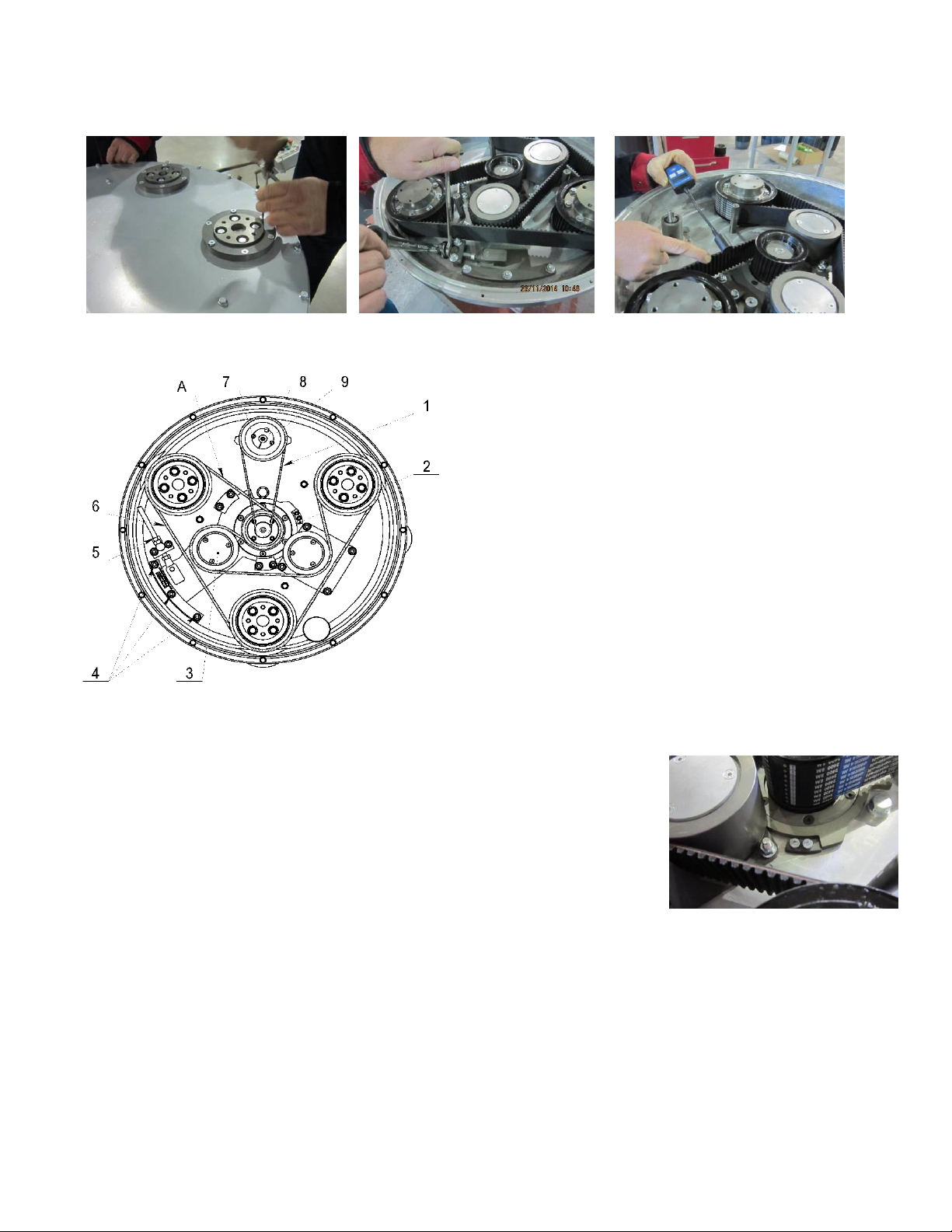
8.8 TENSIONING AND REPLACING THE BELTS
The transmission of the machine runs two timing belts (a main belt that
rotates the plates (and tools) and an auxiliary planetary belt which propels
the rotation of the head as a whole). To change the main belt, remove all
plate holders and adapters. There will be a seal to remove as well. Check
any friction surfaces for wear, and replace if necessary. To remove the
bottom cover, unscrew the bolts at the circumference of the cover, as well
as those in the spacers. We recommend that all seals (O‐Rings in the pacers
and seal around the cover) be replaced when changing belts.
Figure 8.8.4 shows the scheme of the belts. To remove the old bels first
remove the planetary belt (1) and then the main belt (6).
To remove the main belt (6), loosen nuts (4) and (5) enough to be able to
turn the tensioners (3) around the central axle. Clean the washers and
surrounding area, and check all bearings of pulley units/tensioners for too
much clearance or rolling noise. Rotating the tensioner will allow the centre
distance to be reduced in such that the timing belt may be fitted without
force. Installation with the use of force is NOT permissible at any time as
this can damage the high quality, low stretch tension cord and other
components. This damage is often not visible. Arrange the belts in pos.6 as
per the scheme, paying attention to their orientation at every pulley.
Loosen the nuts (5) to the end of the bolt, and fully loosen the nuts on the
half moon (4), allowing the rotation of the tensioners with minimal force.
Using nuts (5), tighten the belt, double checking the position/orientation of the belt and the
gearing in each pulley.
Rotate the gear while tensioning to allow regular distribution of tension along the belt.
Measure the tension using a Frequency Tension Tester (Optibelt 3 TT) (Fig. 8.8.3). Tension in
span “А” of the belt should be 120‐130Hz. It is possible to use the pre‐installed support (Fig.
8.8.4‐2)(Fig. 8.8.5) as a reference to stop the tensioner at the desired belt tension, provided
that the supports have not been moved from their factory position.
ATTENTION:NEVER “OVER” TENSION THE BELT, THE BELT WILL BE DESTROYED AND IT WILL NEVER RECOVER ITS ORIGINAL
TENSION
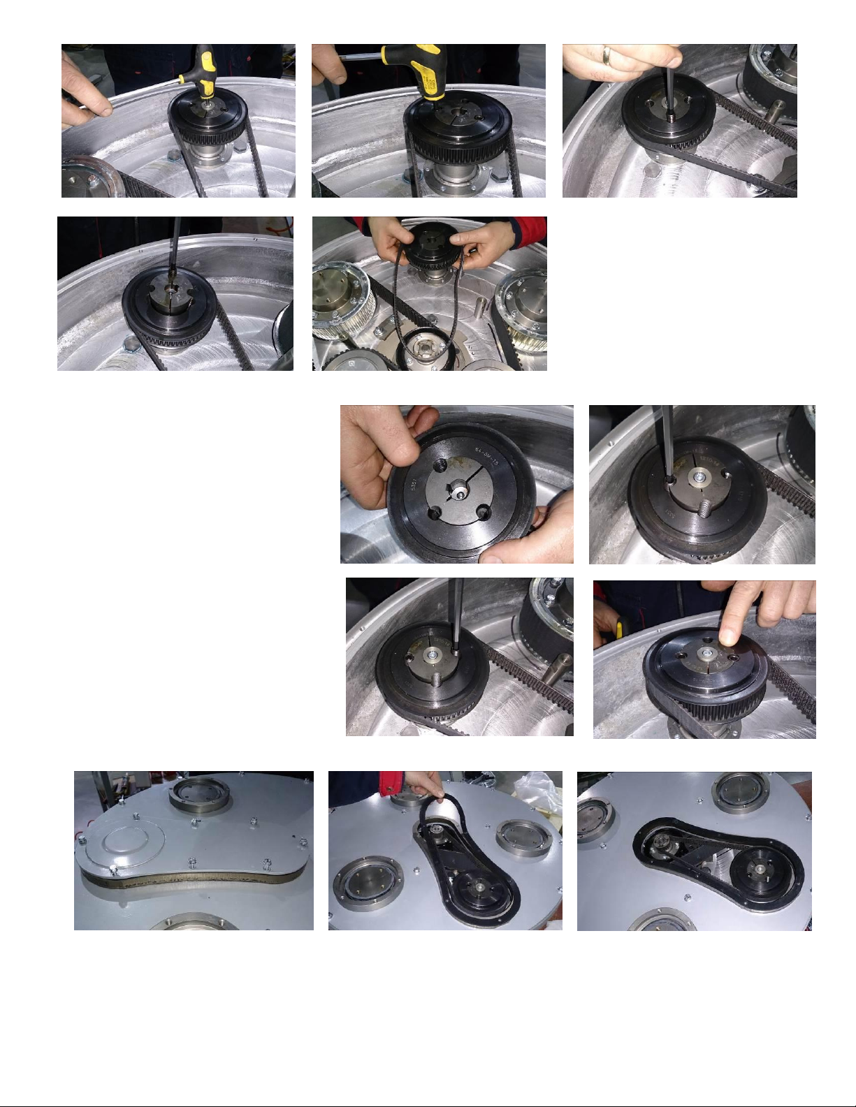
To remove the planetary belt (Fig.8.8.4‐1), unscrew the screw of the front washer (Fig.8.8.6) and the two screws of the conical sleeve
(Fig.8.8.7). Screw one of the removed screws into the free thread(Fig.8.8.8) to push the washer down (Fig.8.8.9); take off the conical
sleeve and the belt (Fig.8.8.10).
24
Page 25
Superabrasive User Manual Original Language Lavina® 25LEU 5/2019
Figure 8.8.9
Figure 8.8.10
Figure 8.8.6
Figure 8.8.7
Figure 8.8.8
Figure 8.8.17
Figure 8.8.16
Figure 8.8.15
Figure 8.8.11
Figure 8.8.12
Figure 8.8.14
Figure 8.8.13
The reassembly is the same process in reverse.
It is important to match the threads of the
conical sleeve and the belt washer(Fig.8.8.11).
Put the front washer (Fig.8.8.12), on the screw ‐
using “blue” thread locking adhesive.
Tightening force of the bolts has to be
4,5...6N.m(3,3...4,4 ft/lbs). Carefully replace
the two binder screws while leaving the
central thread open.(Fig.8.8.12)(Fig.8.8.13).
Insert the screws by alternating at 1.5
revolution each until the conical sleeve pulls
up the belt pulley. The conical sleeve must
be aligned in height with the belt
washer(Fig.8.8.14).
Dismounting the planetary belt is
possible without removing of the Bottom
cover assembly by unscrewing the eight
bolts and removing the service window
cover and the sealing(Fig.8.8.15)(Fig.8.8.16)
to access the planetary belt (see 8.8.17)
25
Page 26
Superabrasive User Manual Original Language Lavina® 25LEU 5/2019
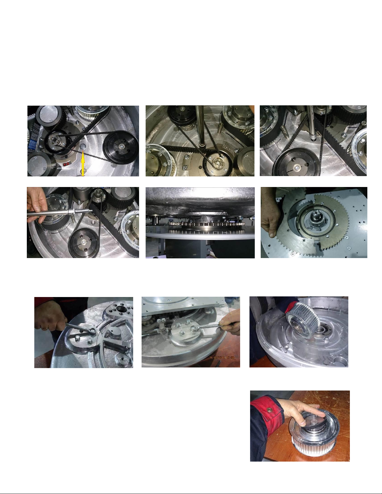
Figure 8.9.1
Figure 8.9.2
Figure 8.9.3
Figure 8.9.4
Figure 8.9.5
Figure 8.9.6
Figure 8.10.1
Figure 8.10.2
Figure 8.10.3
Figure 8.10.4
8.9 REPLACING THE DRIVEN PLANETARY GEAR (SPROCKET)
Remove the planetary chain and tensioner (see 8.6 ‐ MOUNTING NEW PLANETARY CHAIN).
Dismount the tool holders, sealers, and bottom cover (TENSIONING AND REPLACING THE BELTS). Unscrew the cap to access the
fastening bolts of the driven gear (Fig.8.9.1)(Fig.8.9.2). Rotate the main head such that you see a fastening bolt of the gear (Fig.8.9.3)
through the hole.
You will need a 10mm magnetic deep metric socket with an outside diameter of no more than 11/16 in to unscrew the six bolts
(Fig.8.9.3)(Fig.8.9.4) (Fig.8.9.5). Once these are removed, remove the two halves of the gear. The
gear is composed of two symmetrical halves(Fig.8.9.6). Mount them in reverse order.
8.10 REPLACING THE PULLEY UNITS
Dismount guard, top cover, maintenance window chain tensioner, driven chain wheel, bottom cover and belts as previous
described.
Unscrew the four bolts of each pulley between the base plate and the motor base
disc (Fig.8.10.1)(Fig.8.10.2) and dismount the pulley (Fig.8.10.3).
A seal (Fig.8.10.4) should be placed on top of the pulley before mounting.
26
Page 27
Superabrasive User Manual Original Language Lavina® 25LEU 5/2019
Figure 8.12.1
Figure 8.11.3
Figure 8.11.2
Figure 8.11.1
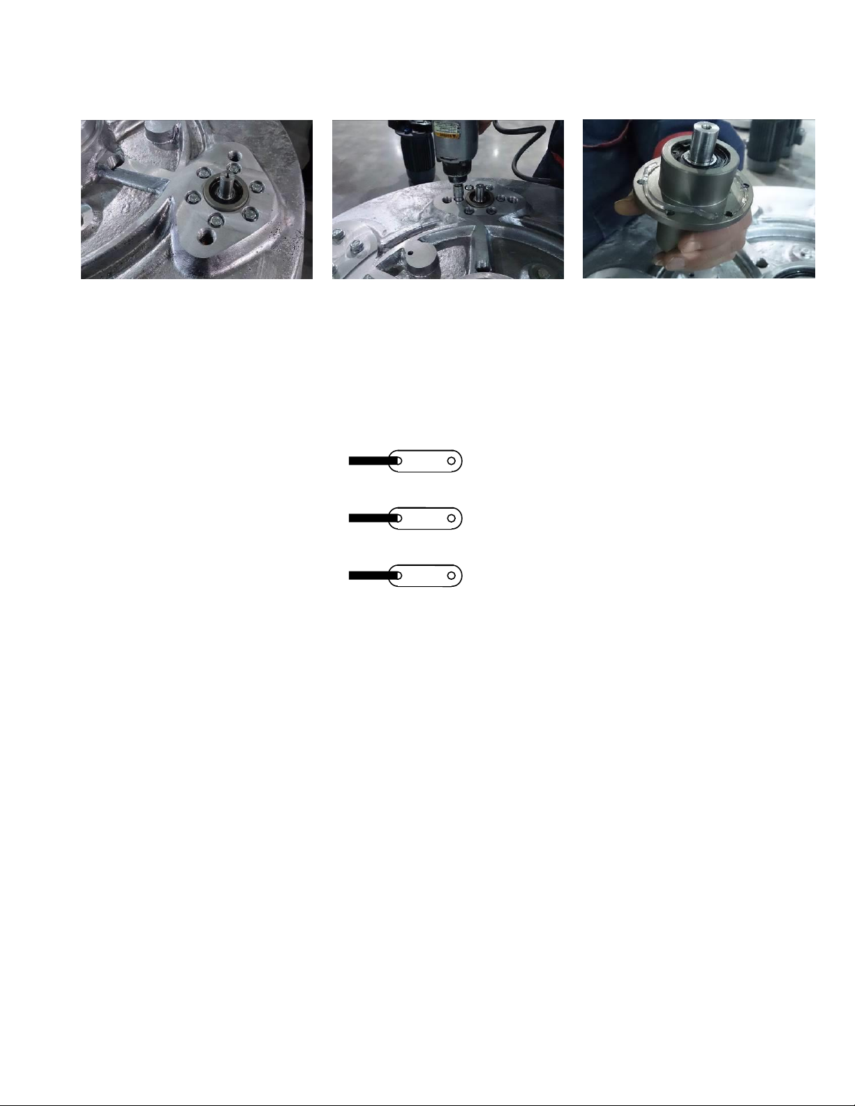
8.11 REPLACING THE PLANETARY UNIT
Unscrew the six bolts (Fig.8.11.1)(Fig.8.11.2) and press down the planetary unit.
When mounting back secure with sealant (fig.8.11.3).
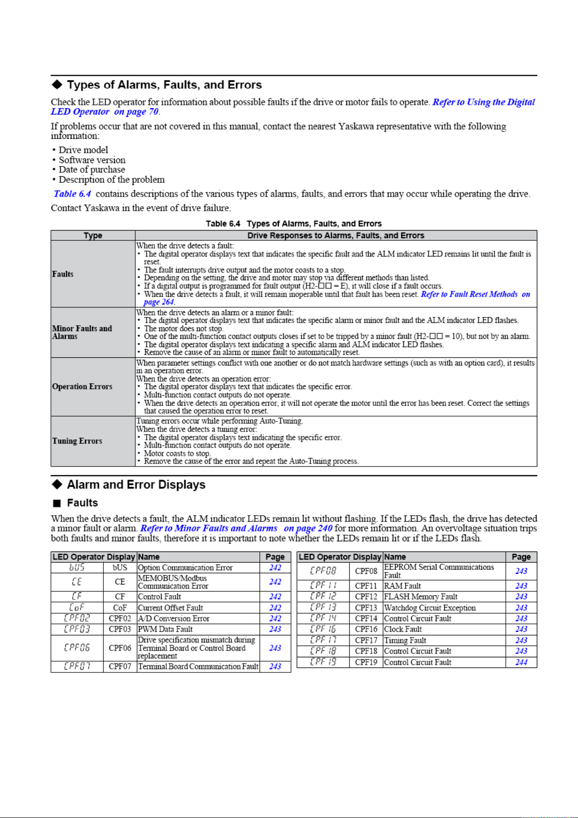
8.12 MOTOR CONNECTION
In case the motor is being replaced, please follow the cable connections in the figures below (Fig.8.11.1).
Lavina® 25LEU
The motor is connected in “Star”
380 Volt, reminder for
the wire connection of the motor
27
Page 28
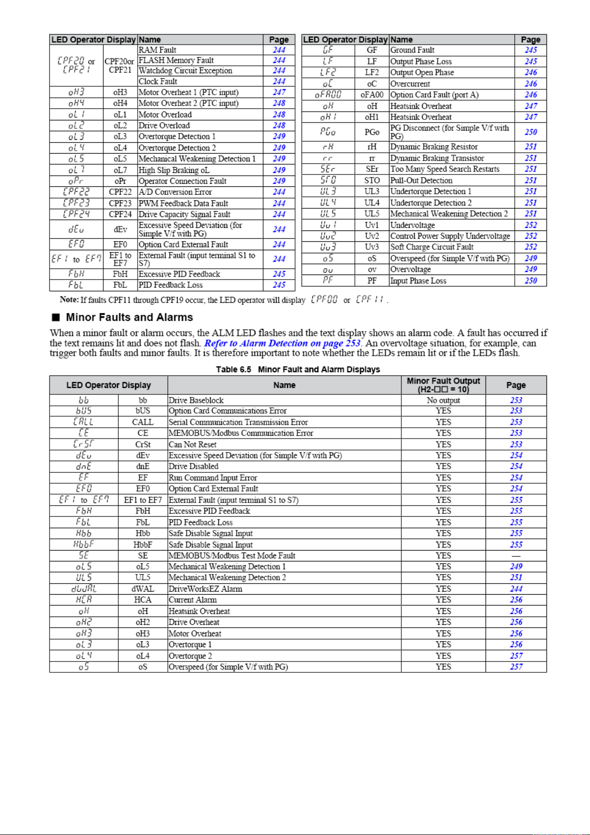
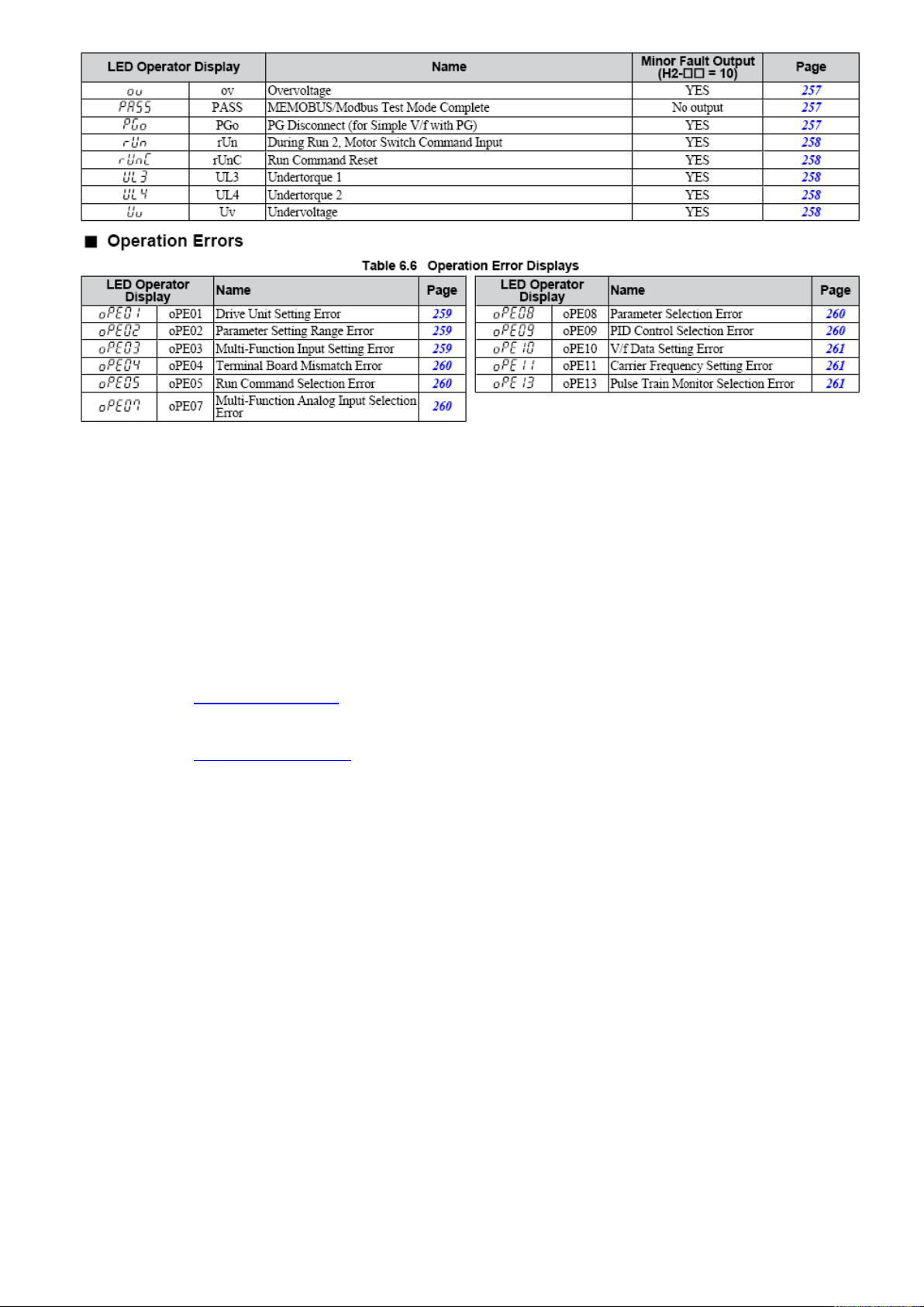
8.13 FAULT DIAGNOSIS INVERTER YASKAWA V1000
Pages are referring to
Yaskawa Electric SIEP C710606 18A YASKAWA AC Drive – V1000 Technical Manual
28
Page 29
Superabrasive User Manual Original Language Lavina® 25LEU 5/2019
29
Page 30
Superabrasive User Manual Original Language Lavina® 25LEU 5/2019
9. DISPOSAL
If your machine after time is not usable or needs to be replaced, send the machine back to Superabrasive or a local
distribut
or, where a professional disposal complying with the environment laws and directives is guaranteed.
10. MANUFACTURER’S CONTACTS
If you need to contact Superabrasive Inc. with technical support questions, below is the contact
information. Address: 9411 Jackson Trail Road, Hoschton GA 30548, USA
Email: [email protected]
Tel.: 706 658 1122
Fax: 706 658 0357
Website: www.superabrasive.com
30
Page 31
Superabrasive User Manual Original Language Lavina® 25LEU 5/2019
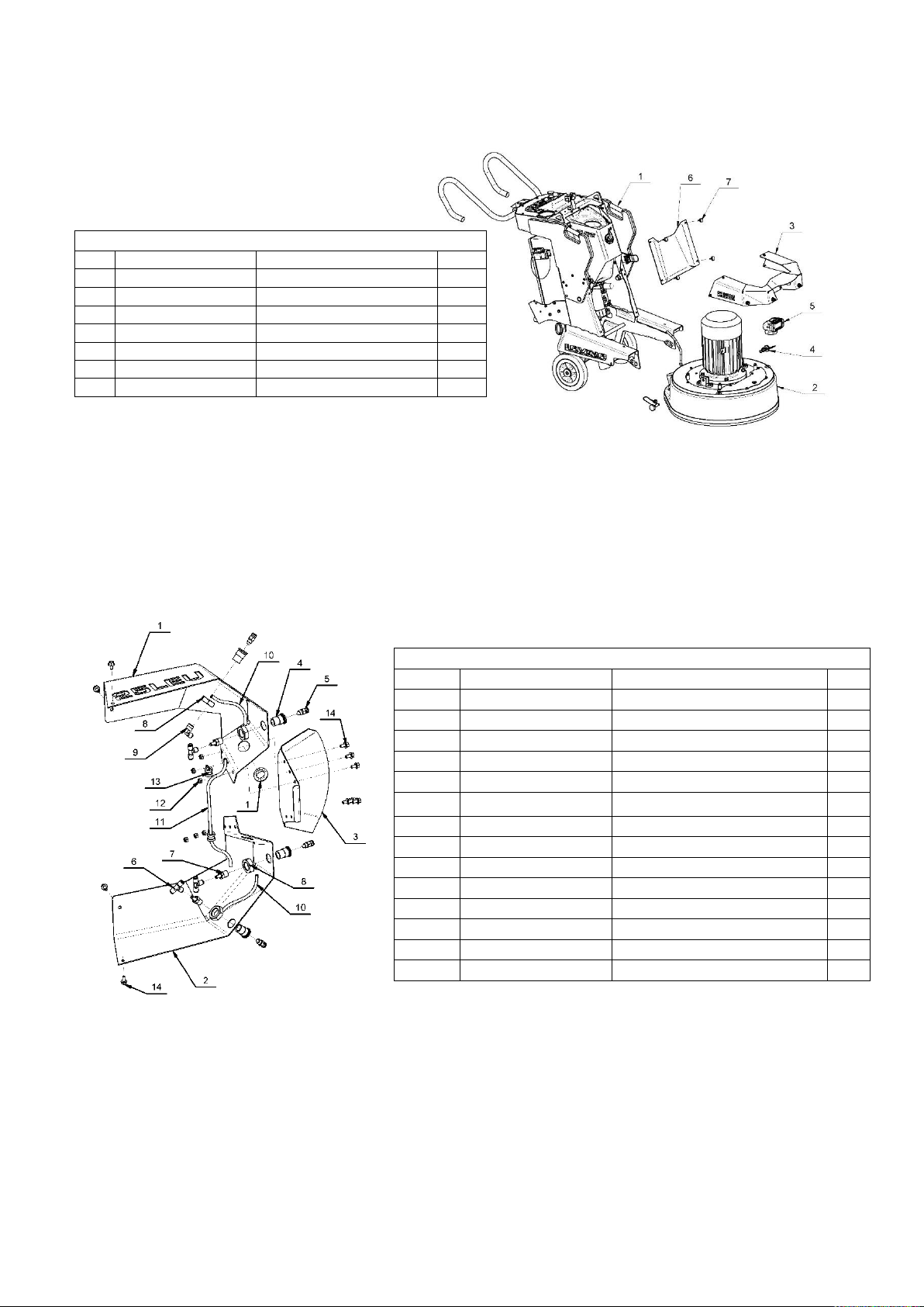
1. LAVINA®25LEU GENERAL PARTS
No.
Item No.
Description
Pcs. 1 L25LEU20.00.00
Carriage
1
2
L25LE10.00.00
Main Head
1 3 L25LEU01.00.00
Bumper
1 4 L25SPS-07.03.00.00
Pin Assembly
2
5
A50.00.00.00
LED light with magnetic base
1 6 L20E20.00.03
Front cover
1 7 30301230251
Screw M5x16ISO7380F/10.9/
4
2. LAVINA® 25LEU BUMPER
No.
Item No.
Description
Pcs.
1
L25LEU01.00.01 -K
Bumper right part
1
2
L25GE01.00.02
Bumper left part
1 3 L20GX-01.00.03
Bumper middle part
1 4 L20GX-01.10.02
Insert for Misting nozzle
4 5 30313000064
Misting nozzle
4
6
30313000343
EQUAL TEE - 1/4 INC - 1/4 INC
3
7
30313000344
Adapter 1/4 INC - NPT1/4
3 8 30301240015
Nut M20x1.5DIN439-B
4 9 30313000348
Fixed Elbow NPT Thread
1
10
025X130
PE Tube
2
11
025X300
PE Tube
1
12
30301240103
Nut M6DIN985
6
13
30308000412
Clamp
2
14
30301210048
Bolt M6X12DIN6921
10
11. SPARE PARTS
ASSEMBLY AND PARTS SPECIFICATIONS
31
Page 32
Superabrasive User Manual Original Language Lavina® 25LEU 5/2019
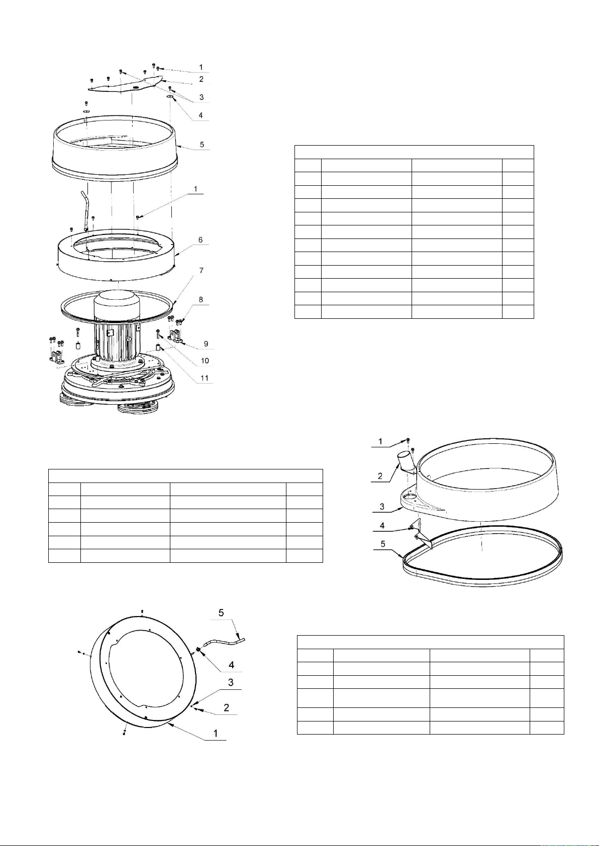
3. LAVINA® 25LEU TOP COVER 1 PARTS
No.
Item No.
Description
Pcs. 1 30301210048
Bolt M6X12DIN6921
7 2 L25LE19.20.00-1
Inspection Cover
1 3 30301210051
Bolt M6X16DIN6921
4
4
30301221022
Washer D35X1.4
2
5
L25Е10.70.00
Gard Assembly
1 6 L25E19.00.00-1
Top Cover Assembly
1 7 30302000049
V-Ring Type A
1 8 30301210031
Bolt M8X20DIN6921
8 9 L25E15.10.00
Fork
2
10
30301210092
Bolt M8X40DIN6921
4
11
L20GX-15.00.29
Bushing
4
4. LAVINA®25LEU GARD ASSEMBLY
No.
Item No.
Description
Pcs. 1 30301210117
Bolt M6X20DIN6921
2 2 L30E10.71.00
Vacuum Port
1 3 L25GЕ10.70.01
Guard
1 4 L25Е10.71.00
Bottom Vacuum Port
1 5 FBL1350-2280
Brush
1
5. LAVINA®25LEU TOP COVER ASSEMBLY
No.
Item No.
Description
Pcs. 1 L25E19.10.00-1
Top Cover
1 2 30301210007
Bolt М5X10DIN933
4
3
30301220001
Spring Washer
М5DIN127B
4
4
30308000419
Clamp
1 5 L20GX-19.00.05
Tube
1
32
Page 33
Superabrasive User Manual Original Language Lavina® 25LEU 5/2019
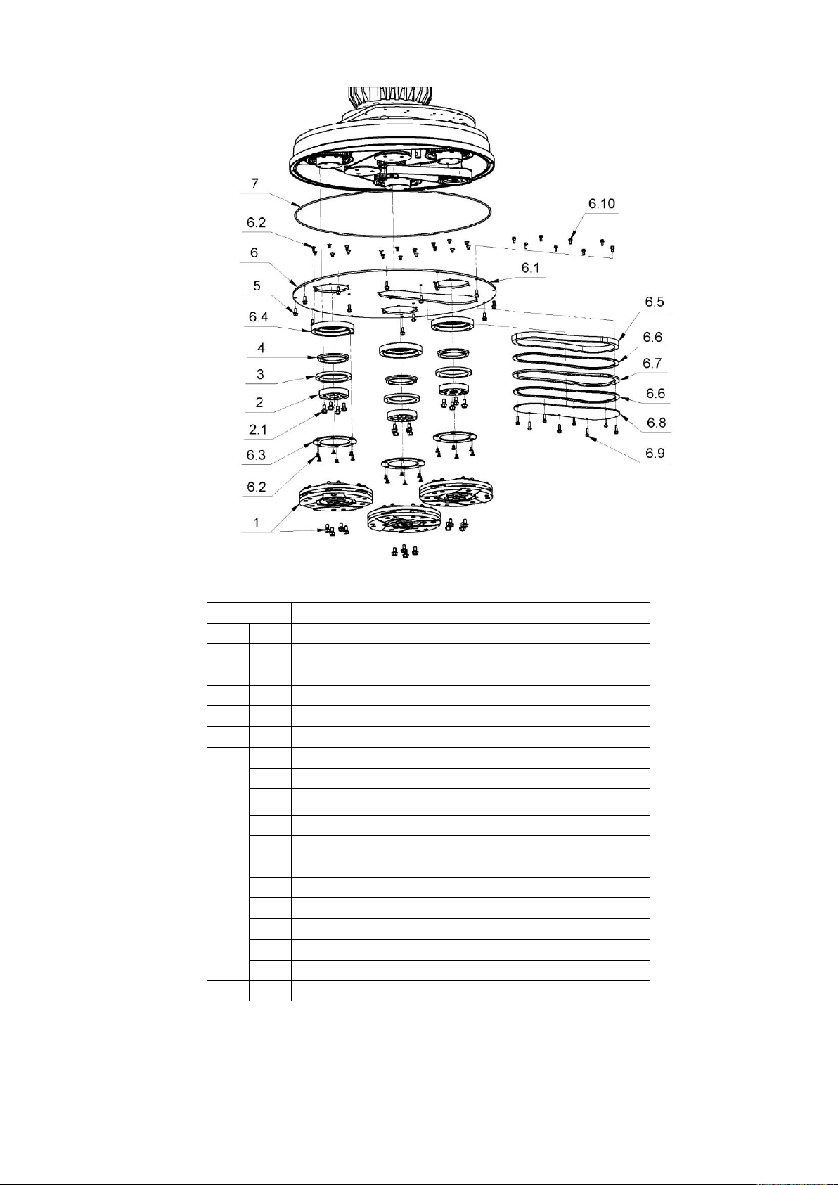
6. LAVINA® 25LEU BOTTOM COVER 1 PARTS
No.
Item No.
Description
Pcs. 1
A63.00.00
Tool Holder A63
3 2
A42.03.00
Adaptor
3
2.1
30301210072
Bolt М8х16DIN6921
4 3
30309000000
Felt Ring
3 4
30302000005
V-Ring Type A
3 5
30301210051
Bolt М6х16DIN6921
15 6
L25X-14.00.00-R2
Bottom Cover Assembly
1
6.1
L25X-14.00.01
Bottom Cover
1
6.2
30301230017
Screw
M6X10DIN7991/10.9/
36
6.3
L25LS-14.00.03
Outer Cover
3
6.4
L25LS-14.00.02
Flange
3
6.5
L25X-14.00.05
Flange
1
6.6
L25X-14.00.04
Sealer Inspection Cover
2
6.7
L25X-14.00.06
Pad 2
1
6.8
L25X-14.10.01-R2
Inspection Cover
1
6.9
30301210105
Bolt M5X20DIN6921
8
6.10
30301210030
Bolt M5X12DIN6921
8 7
D4X2X1900
Seal
1
33
Page 34
Superabrasive User Manual Original Language Lavina® 25LEU 5/2019
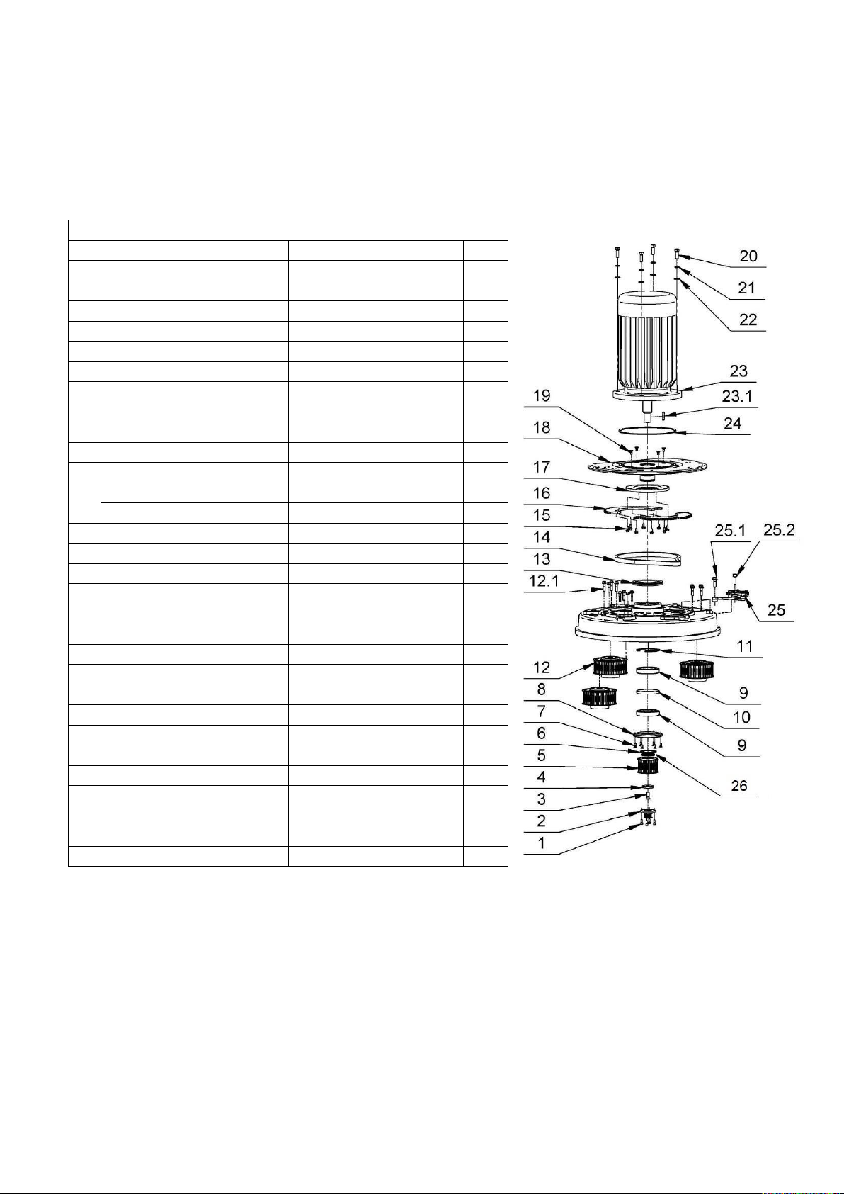
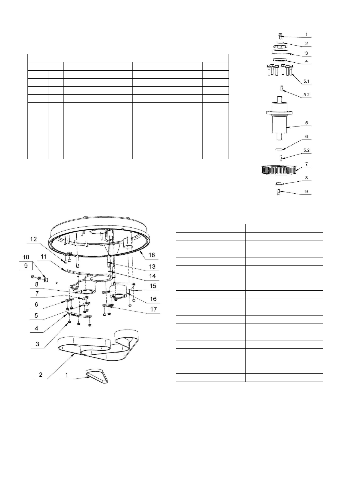
7. LAVINA® 25LEU PLANETARY DRIVE PARTS
No.
Item No.
Description
Pcs.
1 30301230098
Screw M6X16DIN912
4
2 L25X-03.00.00-R2
Pulley
1
3 30301230201
Screw M16X35DIN7991/10.9/
1
4 L25LX-10.00.55
Front Washer
1
5 L25LX-10.10.00
Central Pulley
1
6 30301250002
Retaining Ring B65DIN471
1
7 30301230002
Screw М6х16DIN7991
6
8 L25X-10.00.17
Cap
1
9 30303000012
Roller Assembly
2
10 L25SPS-00.00.00.34
Distance Ring
1
11 30301250009
Retaining Ring
1
12
L25X-11.00.00
Pulley Unit Assembly
3
12.1
30301210032
Bolt M8X35DIN6921
4
13 30302000008
V-Ring Type A
1
14 08BH-1-79
Chain
1
15 30301210051
Bolt M6X16DIN6921
8
16 L25X-15.00.12
Chain Pulley
2
17 L25X-15.00.03
Flange
1
18 L25LE15.20.00
Base plate
1
19 30301230056
Screw M8X16DIN7991
4
20 30301210066
Bolt M16X30DIN933
4
21 30301220006
Spring Washer M16DIN127B
4
22 30301221008
Washer M16DIN125A
4
23
30305000019
Electro Motor
1
23.1
30301260072
Key DIN6885A12X8X36
1
24 D4X2X850
Seal
1
25
L25X-17.00.00
Chain Tensioner
1
25.1
30301210021
Bolt M10X35DIN6921
1
25.2
30301230007
Screw M10x35DIN912
1
26 L25LX-10.00.29
Distance Ring
1
34
Page 35
Superabrasive User Manual Original Language Lavina® 25LEU 5/2019
7.1. LAVINA® 25LEU PULLEY UNIT ASSEMBLY
No.
Item No.
Description
Pcs.
1 30301210030
Bolt M5X12DIN6921
1 2
L25X-10.00.46
Front Washer
1 3
L25E16.20.00-1
Chain Pulley Assembly
1 4
30302000032
V-Ring Type A
1 5
L25Х-16.00.00-R2
Bearing Body
1
5.1
30301210107
Bolt M6X25DIN6921
6
5.2
30301260060
Key
2 6
L25Х-16.00.03
Distance Ring
1 7
L25X-04.00.00
Pulley Unit Assembly
1 8
L25X-10.00.44
Front Washer
1 9
30301230009
Screw M5X12DIN912
1
8. LAVINA® 25LEU BOTTOM COVER 2 PARTS
No.
Item No.
Description
Pcs. 1 30308000152
Timing Belts
1
2
30308000130
Timing Belts
1
3
30301240095
Nut M8DIN6923
13 4 L25L-10.00.14
Sector
1
5
L25L-10.00.12
Sector
1
6
L25L-10.00.07
Support
2 7 L25L-10.00.11
Sector
1
8
L25X-12.00.00-R1
Tensioning Support
1
9
L32C-14.20.04
Nut
1
10
30301240099
Nut M10DIN934
2
11
L25L-10.00.13
Sector
1
12
L25L-10.00.08
Washer
2
13
L25X-10.00.13
Distance Bolt
3
14
30302000105
O-Ring
3
15
L25X-10.00.34
Sector
1
16
L25X-13.00.00-R1
Deflection Pulley
1
17
L25X-10.00.35
Sector
1
18
L25E10.00.01-K
Disc
1
35
Page 36
Superabrasive User Manual Original Language Lavina® 25LEU 5/2019
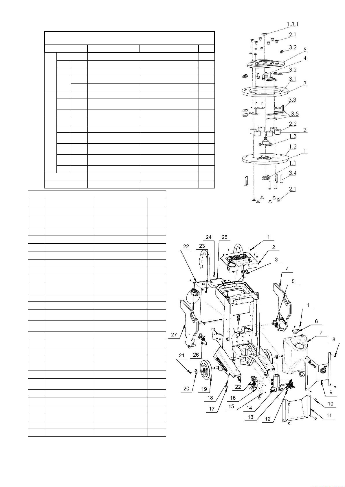
9. LAVINA®25LE TOOL HOLDER PARTS/SEE ALSO FIG.8.7.13/
(POS.1 INCLUDE POS.1.1;1.2;1.3/POS.1.3 INCLUDE POS.1.3.1 and etc.)
No.
Item No.
Description
Pcs.
1
A63.10.00
Quick Change Assembly
1
1.1
A63.12.00
Keylock Set
1
1.2
A41.11.00
Quick Change plate
1
1.3
.
A41.12.00
Security set
1
1.3.1
A41.00.05
Washer A41
1
2
A25.00.10-K
Buffer with two screw
6
2.1
30301230161
Screw
M8X12DIN7991/10.9/
12
2.2
A25.00.10
Buffer
6
3
A41.20.03-K
Driving Set A41
1
3.1
A41.20.03
Elastic Element
1
3.2
30301240124
Self Locking Nut
M6DIN980V
12
3.3
30301230131
Screw
M6X40DIN7991/10.9/
6
3.4
30301230123
Screw
M6X30DIN7991/10.9/
6
3.5
A41.21.00
Set of plates
1 4 30301210072
Bolt М8х16DIN6921
4 5 A41.20.01
Flange
1
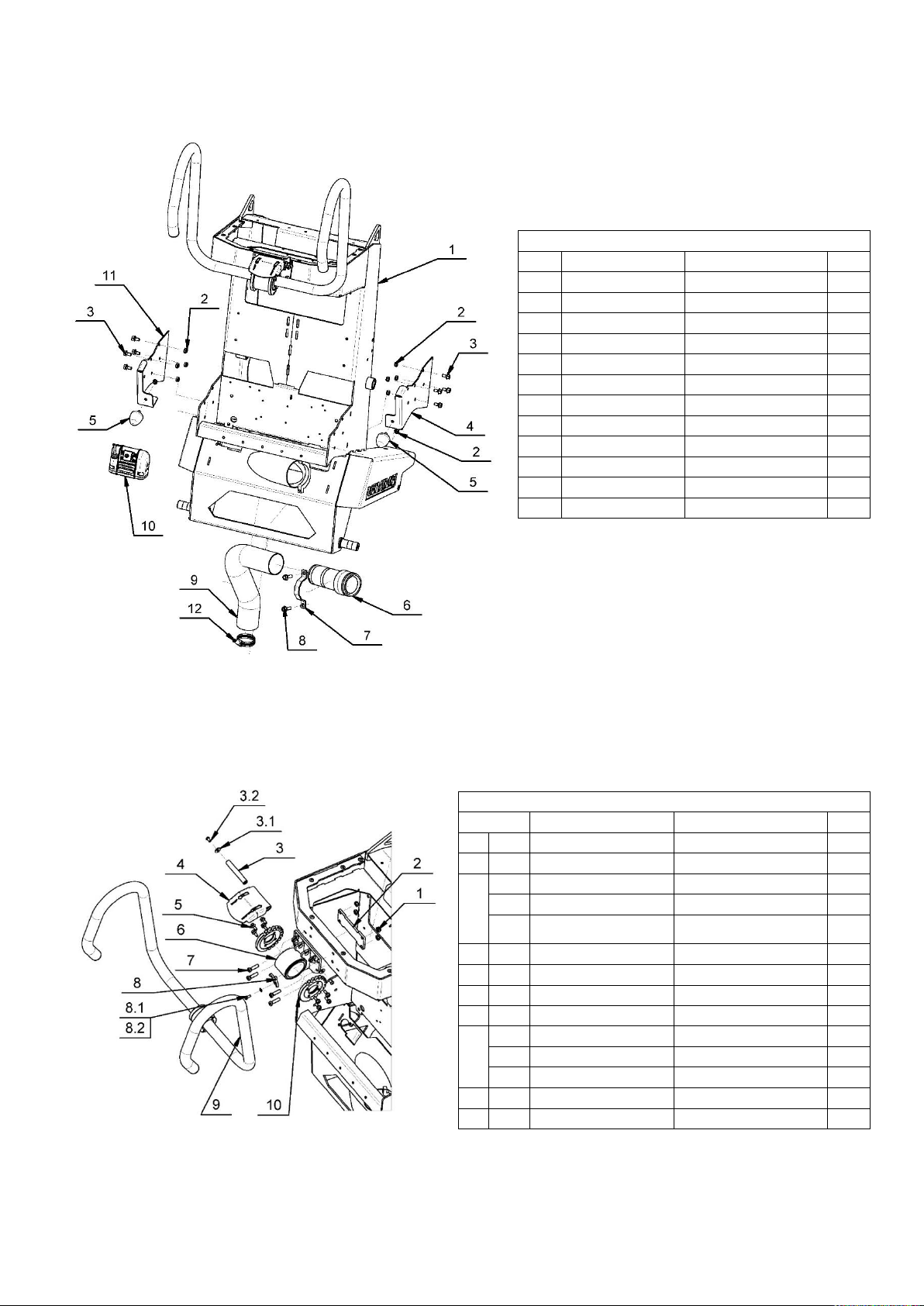
10. LAVINA® 25LEU CARRIAGE PARTS 1
No.
Item No.
Description
Pcs.
1
30301230243
Screw
M6x16ISO7380F-10.9
10 2 L20E22.00.00
Control board
assembly
1
3
30350000044
Phone clip mount
1
4
L20GX-20.20.00
Left Weight
1
5
L20GX-20.40.00
Left Weight Support
1 6 L20E20.10.00
Top Bracket
1 7 A62.00.00.00
Tank Assembly
1 8 30301210051
Bolt M6X16DIN6921
4 9 L25E20.50.00
Front panel
1
10
30301230251
Screw
M5X16ISO7380F/10.9/
4
11
L20E20.00.03
Front cover
1
12
А47.00.00.00
Water Valve assembly
1
13
А49.00.00.00
Regulator for Water
pump with connectors
1
14
А60.00.00.00
Water pump with
connectors
1
15
30301240090
Nut M5DIN985
4
16
30301221002
Washer M5DIN125A
4
17
30310000006
Pad
2
18
30301240103
Nut M6DIN985
2
19
30312000043
Wheel
2
20
L25X-20.00.03-1
Wheel Cap
2
21
30301230015
Screw
M10x16DIN7991/10.9/
2
22
L25LEU30.00.00
Control Box
1
23
30301210031
Bolt M8X20DIN6921
4
24
30301240106
Nut М8DIN985
4
25
30301221004
Washer M8DIN125A
4
26
L20GX-20.30.00
Right Weight Support
1
27
L20GX-20.10.00
Right Weight
1
36
Page 37
Superabrasive User Manual Original Language Lavina® 25LEU 5/2019
11. LAVINA® 25LEU CARRIAGE PARTS 2
No.
Item No.
Description
Pcs. 1 L25E21.00.00-К
Frame
1 2 30301240106
Nut М8DIN985
10 3 30301210072
Bolt M8X16DIN6921
8 4 L20GX-20.00.21-1
Support right
1 5 30310000005
Pad
2 6 E250-AL
Camlock Fitting
1 7 L25GE20.00.02
Clamp
1 8 30301210032
Bolt M8X35DIN6921
2 9 D63X470C
Soft Vacuum Hose
1
10
30311000749
LED Light
1
11
L20GX-20.00.22-1
Support left
1
12
30308000399
Clamp 50_70DIN3017
1
12. LAVINA® 25LEU CARRIAGE PARTS 3
No.
Item No.
Description
Pcs. 1
30301240106
Nut М8DIN985
4 2
L20GX-23.00.03
Handle support plate
1 3
L20GX-23.00.02-1-K
Pin
1
3.1
30301221012
Washer М6DIN9021
2
3.2
30301230250
Screw
M6x12ISO7380-1/10.9/
2
4 L20GX-23.20.00
Handle locking bit
1 5
30301210051
Bolt M6X16DIN6921
8
6 L20GX-23.30.00
Handle support
1
7 30301230257
Screw M8x30DIN7984
4 8
L20GX-23.00.11-K
Lock Lever
1
8.1
30301210109
Bolt M5x14DIN933
1
8.2
30301221002
Washer М5DIN125A
1
9 L13GX21.10.00
Handle Assembly
1
10 L20GX-23.00.01
End Cover
2
37
Page 38
Superabrasive User Manual Original Language Lavina® 25LEU 5/2019
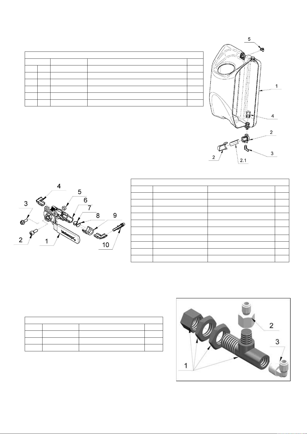
13. LAVINA® 25LEU WATER TANK
No.
Item No.
Description
Pcs.
1
A62.00.00.01-K
Water Tank-K
1
2
30323000209
Filter_LP 1/4 FNPT GFPP CB 80X80 SST CG BN
1
2.1
30313000077
Filter 1 3 30313000342
Fixed Elbow Male NPTF Thread -3/8 INC- NPT1/4
1
4 30316000001
Filter 1 5 30313000348
Fixed Elbow NPT Thread
1
14. LAVINA® 25LEU WATER BALL VALVE
No.
Item No.
Description
Pcs.
1
30316000066
Ball valve
1
2
30301230098
Screw M6x16DIN 912
1
3
30301210110
Bolt M5x16DIN6921
1
4
30313000348
Fixed Elbow NPT Thread
3
5
30301240103
Nut М6DIN985
1
6
30313000057
UNIJET Body
1
7
30313000058
TEEJET Cup Strainer
1
8
A47.00.00.01
Orifice Plate
1
9
30313000060
UNIJET ADAPTER
1
10
30313000339
Tube To Hose Stem
1
15. LAVINA® 25LEU WATER PUMP REGULATOR
No.
Item No.
Description
Pcs. 1 30313000055
Water Pump Regulator
1 2 30313000349
FEMALE STUD FITTING
1 3 30313000348
Fixed Elbow NPT Thread
1
38
Page 39
Superabrasive User Manual Original Language Lavina® 25LEU 5/2019
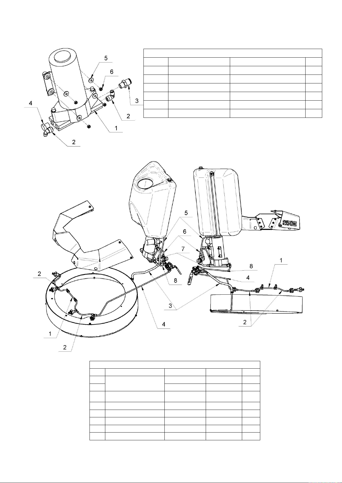
16. LAVINA® 25LEU WATER PUMP
No.
Item No.
Description
Pcs. 1 30326000002
Pump 113C/M8234
1 2 30313000348
Fixed Elbow NPT Thread
2 3 30313000341
Stud Fitting
1 4 30313000056
Male Hex Plug
1 5 30301221015
Washer M5DIN9021
4 6 30301240090
Nut M5DIN985
4
17. LAVINA® 25LEU WATER INSTALLATION
No. Item No.
Description
Pcs.
1
See table 2 “BUMPER”
025X300
PE Tube
1 2 025X130
PE Tube
2
3
See table 5 “TOP COVER
ASSEMBLY”
L20GX-19.00.05
Tube
1
4
Ball valve - Bumper
025X730
PE Tube
1 5 Regulator – Water tank in
025X730
PE Tube
1 6 Pump out - Regulator
025X300
PE Tube
1
7
Pump in – Water tank out
038X500
PE Tube
1
8
Pump out - Ball valve
025X300
PE Tube
1
39
Page 40
Superabrasive User Manual Original Language Lavina® 25LEU 5/2019
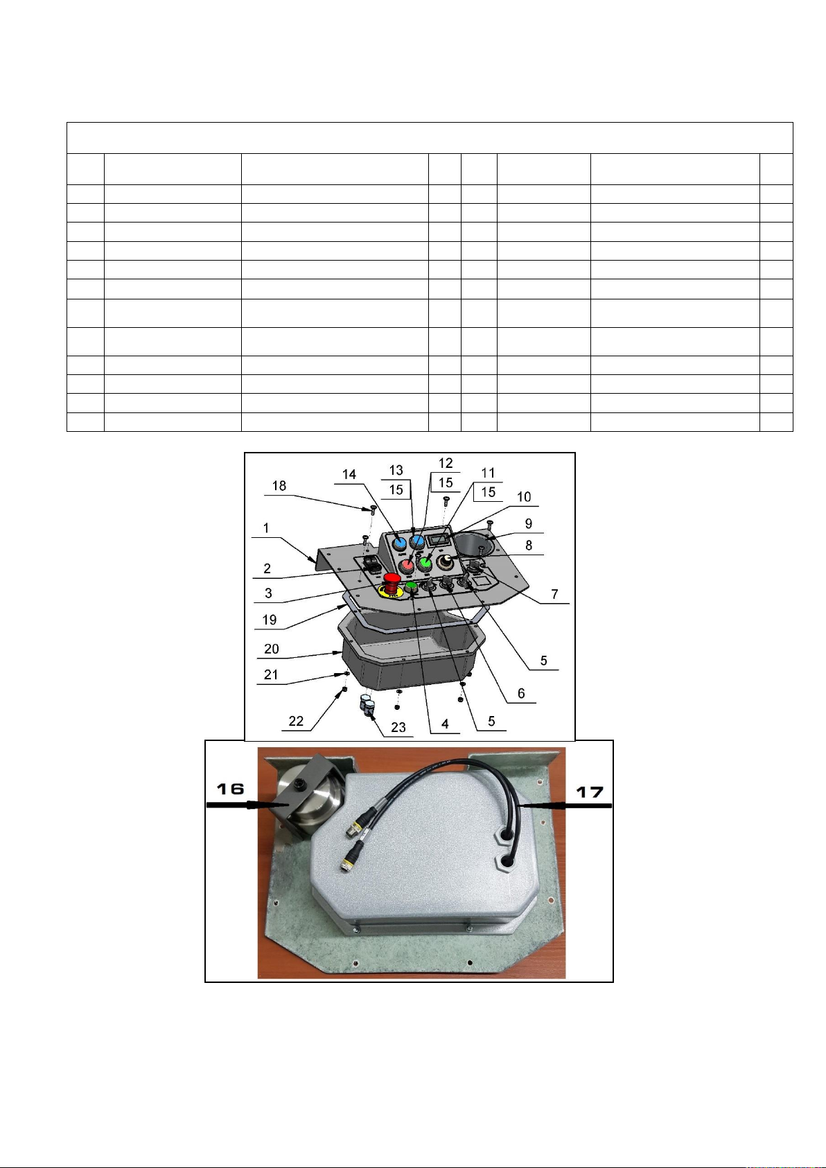
18 CONTROL BOARD ASSEMBLY
No.
Item No.
Description
Pcs.
No.
Item No.
Description
Pcs.
1
L20E22.10.00
Control board assembly kit
1
13
30311000703
Button
1 2 30313000173
USB charger
1
14
30311000741
Glowing button
1
3
30311000717
EMG Button
1
15
30311000750
Cap
1 4 30311000740
Power glowing button
1
16
L20GX-40.20.03
Clamp
1
5
30311000721
Switch 2 17
30311000226
Cable
1
6
30311000731-K
Switch 1 18
30301230264
Screw M6x20ISO7380F-10.9
6
7
30311000732-K
Switch
1
19
L25E22.00.01
Seal
1
8
30311000690
Potentiometer
1
20
L25E22.00.02
Box
1
9
30350000045
Cup holder
1
21
30301221003
Washer M6DIN125A
6
10
30313000150
Tachometer
1
22
30301240103
Nut M6DIN985
6
11
30311000701
Button
1
23
30311000401
Cable Gland 16x1,5
2
12
30311000700
Button
1
Figure 11.9
18 CONTROL BOARD ASSEMBLY
40
 Loading...