

Supeero 606S Assembly Instructions And Directions For Use
SUPEERO
- Systeme GmbH - Im Bärengarten 2 - 72116 Mössin gen
Telefon 07473/94940 FAX: 07473/2 5808
subject to technical alterations 06.2006
www.supeero.de - info@supeero.de
1
AAsssseemmbbllyy iinnssttrruuccttiioonnss aanndd ddiirreeccttiioonnss ffoorr uussee:
:
eelleekkttrroohhyyddrraauulliicc ooppeerraattoorr ffoorr hhiinnggeedd ggaattees
s

SUPEERO
- Systeme GmbH - Im Bärengarten 2 - 72116 Mössin gen
Telefon 07473/94940 FAX: 07473/2 5808
subject to technical alterations 06.2006
www.supeero.de - info@supeero.de
2
PPlleeaassee aatttteenndd tthhee ffoolllloowwiinngg aasssseemmbbllyy iinnssttrruuccttiioonnss !
!
AATTTTEENNTTIIOONN:: TThhee ooppeerraattiioonnss ddeessccrriibbeedd aarree iinntteennddeedd ffoorr aaddeeqquuaatteellyy ttrraaiinneedd aannd
d
qquuaalliiffiieedd uusseerrss !
!
The drive system 606S is designed for installation in residential and industrial hinged gates as an
actuator for the operational automation. The hydraulic drive will be mounted via two attachment
points at the gate pillar and at the flank of gate.
The compact and shapely drive construction could adjust to every gate. The construction and
usage of the materials are aligned for a silent and long lasting operation.
Please use addtional to the electrical adjustment setting of virtue industrial safety equipment as
photo cells, flashing lights and strips, which bring the gate to a halt by contacting the gate. Serious
injuries could be avoided by using appropriate additional safety installations.
Please note at the assembling an start up as well as at the orientation of the user, that there are
significant forces in the range of the gate band through the mounted drive and this forces couldn´t
be controlled by the installed force coupler because of the special mounting form.
In principle every operator should know, that power- operated and remote- controlled gates
should be operated solely when there is intervisibility about the whole opening and closing
stroke
The enclosed condenser must be jammed parallel to the brown and black conductor!!
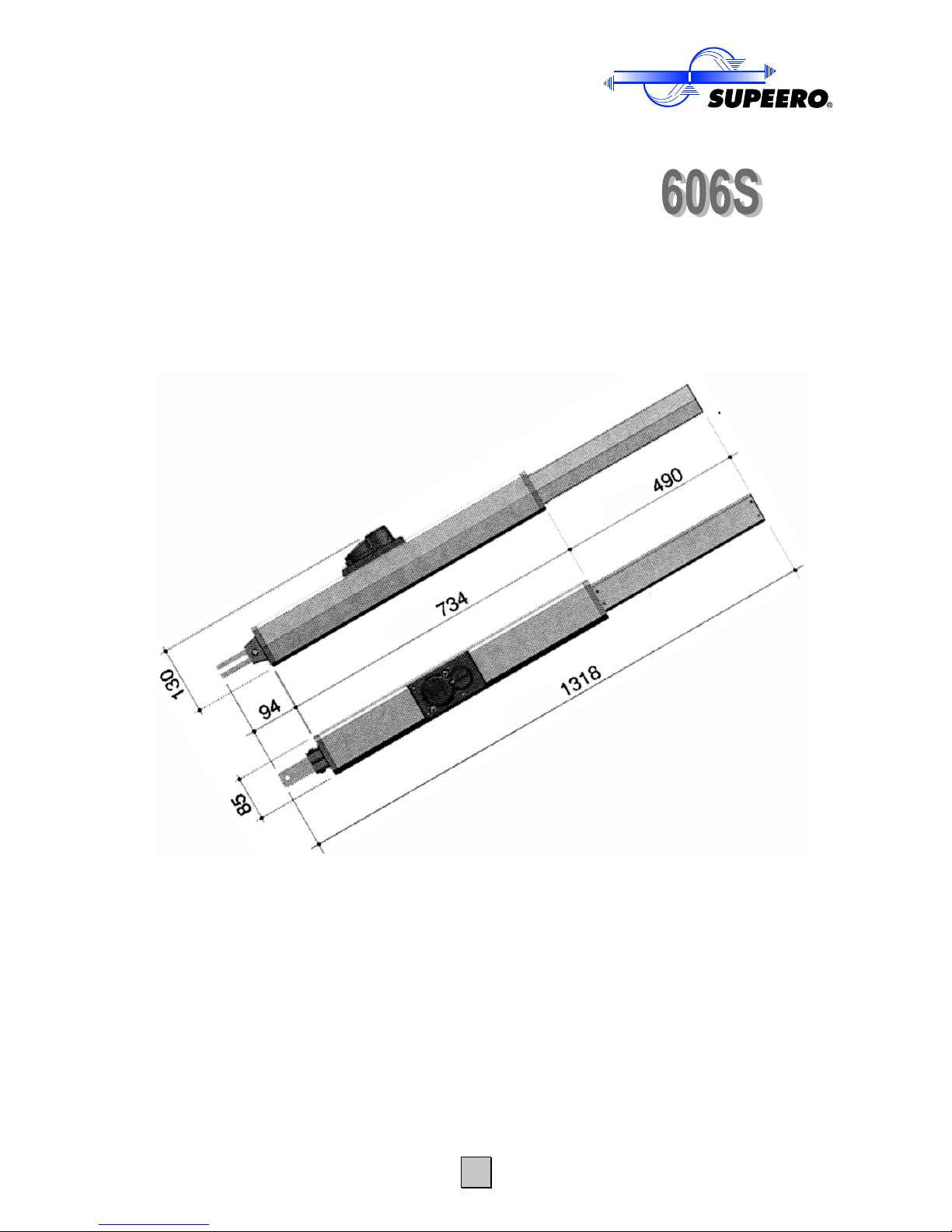
TTeecchhnniiccaall ddaatta
a
mmoottoorr gguuaarrd
d
double acting single phase power supply
with integrated thermo-guard-pill
ddrriivvee ttyyppe
e
electrohydraulic
ssiinnggllee pphhaassee ppoowweerr ssuupppplly
y
230 V / 50 HZ
ppoowweerr iinnppuut
t
1,5 A
aabbssoorrbbeedd ppoowweer
r
170 W
tthhrruusstt ffoorrcce
e
3200 N
wwoorrkk ccyycclle
e
max. 200 x
ddeevviiaattiioonn ccrruuiisse
e
~10 mm/second
ccoonnddeennsseer
r
8 mF
ppuummpp ccaappaacciitty
y
1,0 Liter/minute
QQuuaannttiittyy ooff ooiil
l
1,7 liter
MMoottoorr--nnoommiinnaall rroottaattiioonn ssppeeeed
d
1400 U/minute
rraannggee ooff aammbbiieenntt aaiirr tteemmppeerraattuurre
e
-30° bis +70°
mmaaxx.. aappeerrttuurree aanngglle
e
130°
mmaaxx.. bbrreeaaddtthh ooff wwiinngg wwiitthh ee--lloocck
k
6,0 m
mmaaxx.. wweeiigghhtt ppeerr wwiinng
g
800 kg
mmaaxx.. ddeevviiaattiioonn pprrooffiit
t
360 mm
ssllooww--ssttaarrttiinng
g
no
ccllooggggiinng
g
no
eexxttrreemmee ppoossiittiioonn bbrreeaakkiinng
g
no
wweeiigghhtt ooff mmoottoor
r
12 kg
SUPEERO
- Systeme GmbH - Im Bärengarten 2 - 72116 Mössin gen
Telefon 07473/94940 FAX: 07473/2 5808
subject to technical alterations 06.2006
www.supeero.de - info@supeero.de
3
* IMPORTANT: drive type 606S meets the requirements of DIN EN 12345 only in connection
with additional mounted safety equipment!
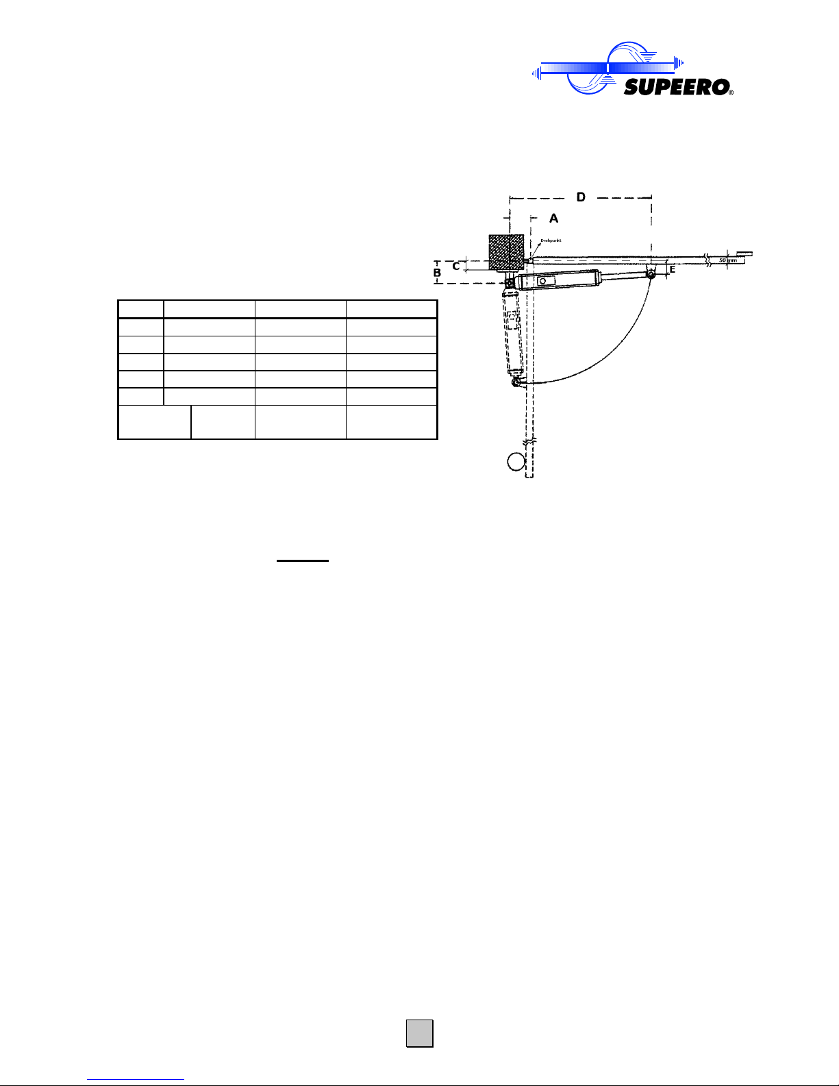
RReeccoommmmeennddeedd eexxtteennttiioonn ggaagge
e
BW = breadth of wing = m / remain dimensions in mm
till BW3,0 m till BW 4,0 m till BW 6,0 m
A
140 160 180
B
140 160 180
C*
max. 90 max. 110 max. 120
D**
max. 1270 max. 1270 max. 1270
E
110 110 110
apertureangle
max.
130°
max.
110°
max.
90°
C* = embrasure depth when fulcrum = as drawing
If the fulcrum is displaced inwards the possible
embrasure depth gage will be accordingly heightened
D** = at closed gate
All dimensions refer to the fulcrum of the gate.
• E = 130 mm, when framework of gate has a wide of 50 mm and fulcrum of gate-band in gate
centerline (see drawing)
• ATTENTION: if the fulcrum of gate is displaced inwards, the dimension will be E = 110 mm,
referring to the centerline of fulcrum.
IMPORTANT: If end switch are not used, mechanical end stopps (e.g.: SUPEERO closure
limiter for upper- and nether floor drive) are mandatory at the gate in open- or closed
positon
ATTENTION: - non observance the drive will get stuck at the gate wing after approx 30°
opening!
AAsssseemmbblliinngg pprreeppaarraattiioon
n
Attach the hind engine mounting flange at the gate pillar.
See that the dimensions A+B are the same size and each don´t undershoot 120mm.
Move the attachment as far as it will go and convert it for about 10mm backward
Maybe it´s necessary that the emergency release must be operated to approx 90° to extricate the
connecting rod easier from the cock.
The outcome of this is the front mounting position at the closed gate.
Justify the device with the aid of a water-level definite horizontal.
 Loading...