

Page 1

- 1 -
EM90
INFRA-RED
THERMOMETER &
THERMOCOUPLE METER
Users
Manual
Page 2

- 2 -
■.Introduction
Thank you for purchasing the SUPCO infrared (IR)
thermometer and thermocouple meter. Please take a
few minutes to browse through this user manual before
you begin to operate the meter to ensure that you are
fully familiarized with how best to operate the meter as
accurately and safely as possible.
This meter combines two precision thermometers in
one unit: a noncontact infra-red thermometer and a
thermocouple thermometer.
This meter can match standard type K-type
thermocouple sensor.
WARNING!
Do not point laser directly at eye or
reflective surfaces.
1.1 Precautions safety measures
To get the best performance from this meter, please
read this user's manual carefully and observe the
detailed safety precautions.
Page 3

- 3 -
1.1.1 During use
1. After abrupt ambient temperature changes, allow
instrument temperature to stabilize for 30 minutes
before taking measurements.
2. Do not expose thermometer to excessive ambient
temperatures.
3. Keep the thermometer clean.
1.1.2 Maintaining the product
l Do not measure in a high temperature, high
humidity locations.
l When not using the instrument for a long time,
please remove the battery and avoid storing in
high temperature and high humidity.
■ Features
1. Display: 4 digit LCD Display
2. Resolution: 0.1℉/ 0.1℃
1℉/ 1℃(thermocouple above 1000℃)
Page 4

- 4 -
3. Range:
Infra-red: -58℉ to 572℉ (-50℃ to 300℃)
Thermocouple: -328 ℉ to 2372 ℉ (-200 ℃ to
1300℃)
4. Accuracy:
Infra-red: ± 5% for -58℉ to -4℉ (-50℃ to -20℃)
± (1.5% reading + 4 ℉ / 2℃)
for -4℉ to 572℉ (-20℃ to 300℃)
Thermocouple: ±(0.2%reading+2℉/1℃)
for -328℉to -148℉(-200℃ to -100℃)
±(0.1% reading +0.7℃/1.4℉) for
-148℉ to 2372℉(-100℃ to 1300℃)
5. Emissivity: 0.95
6. Field of view: 2:1
7. Laser power: Less than 1 mw
8. Response time: 0.5 second
9. Auto power off: 25 seconds (infrared) or
20 minutes (thermocouple)
10. Low battery indicator
Page 5

- 5 -
11. Operating environment:
32℉ to 122℉ (0℃ to 50℃); 0 to 90% RH
12. Storage environment:
14℉ to 140℉ (-10℃ to 60℃,0 to 80% RH
13. Dimensions:
4.76”(L) x 2.36”(W) x 1.18”(H)
121mm(L) x 60mm(W) x 30mm(H)
14. Weight:
6.35 oz (app.) 180 g (app.)
15. Accessories:
K-type thermocouple wire (1)
Lanyard (1)
AAA Batteries (3).
Users manual
Page 6
- 6 -
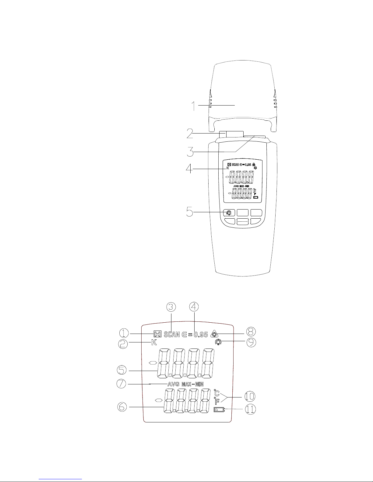
■Instrument Description
1. Sensor cover
2. Infra-red sensor
3. Thermocouple jack
4. LCD display
5. Function key
l LCD Display
LASER
SCAN/H
TYPE
UNIT MODE
ON/OFF
Infrared temperature
thermocouple meter
Page 7

- 7 -
Symbol Designations:
1. Indicates Data Hold
2. Indicates the type of thermocouple
3. Indicates IR measurement
4. Emissivity
5. Measurement Display area
6. Measurement Display area
7. Average/ Maximum / minimum Indicator
8. Indicates laser pointer use
9. Indication back light ON
10.Temperature units
11.Low battery indicator
■ Operating instructions
1. Press the key to turn the unit on. Press
the key again to shift the measurement mode between
infrared or thermocouple.
2. While in Infra-red mode, press the LASER key to
make IR measurements. Point the laser at the target
TYPE
ON/OFF
Page 8

- 8 -
object and press the SCAN/H key for continuous
temperature measurements.
3. In the thermocouple mode, press the SCAN/H key
for data hold. Press the SCAN/H key again to return
the measurement mode.
■ Function Keys
1. TYPE/ON/OFF Key
ON/OFF: Press this key to turn the power ON and
press the key again for more than 2 seconds to turn
the power OFF.
TYPE: Press this key to select infra-red or
thermocouple mode.
2. key
Turns back light on or off.
2. UNIT key
Press this key to select temperature units (℉ or ℃)
Page 9

- 9 -
3. MODE key
Press this key to select AVG, MAX or MIN mode.
4. LASER key
Turns the laser on/ off for IR measurements.
5. SCAN/H key
While in infra-red mode , press this key to take
measurements.
While in thermocouple mode,Press this key for Data
Hold, a icon will be displayed on the LCD. Press
the key once more to cancel the hold function.
7. Auto power off setting
The instrument is factory set for Auto Power Off. The
meter will power itself off after 25 seconds (IR) or 20
minutes (thermocouple) if no key is pressed.
To cancel the auto power off function: press the
LASER key whith power on until the LCD displays all
icons and the back light is on.
Page 10

- 10 -
■ Emissivity and Field of View
Emissivity: Emissivity is a term used to describe the
energy emitting characteristics of a material. The
higher the emissivity value a material has, the more
infrared energy it will emit at a particular temperature.
Most organic materials range in emissivity between
0.85 and 0.98. This thermometer has a fixed
(non-adjustable) emissivity of 0.95. Measuring objects
with an emissivity of less than 0.95 will result in a lower
than actual temperature reading on the display. Be
aware of this characteristic when measuring low
emissivity objects (e.g. shiny, reflective metal objects).
An effective solution is that using the black adhesive
tape to cover the object surface, taking the
measurement when the adhesive tape’s temperature is
the same as the object.
Field of View: The distance to spot ratio for this
thermometer is 2:1. The ideal working range of the
noncontact thermometer is between 25mm and
Page 11

- 11 -
250mm(1 and 10 inches). The field of view is a circular
measurement area approximately equal to the
distance from the target to the unit, divided by 2. To
ensure accurate measurements, the measurement
target must fill or exceed the field of view.
■Maintenance
1. CLEANING INSTRUCTIONS
The meter may be wiped down with a wet sponge or
cloth using a mild, water based detergent.
NOTE:
This unit is not designed for complete submersion or
washing in water.
2. BATTERY REPLACEMENT
Use the following procedure:
When the battery voltage drops below proper
operation range the symbol will appear on
Page 12

- 12 -
the LCD display and the battery needs to be
replaced.
∞ Press the battery cover towards the arrowhead to
open the battery cover.
∞ Replace the battery with three new AAA (1.5V)
batteries.
∞ Replace the battery cover.
WARRANTY
Sealed Unit Parts Co., Inc. warrants that it will repair or
furnish without charge a similar product to replace any
product which, within the specified warranty term after the
date of sale by the Wholesaler, is proved to the satisfaction
of Sealed Unit Parts Co., Inc. , to have been defective at
the time it was sold. Said warranty is in effect only when
said item is used in accordance with the instructions and
recommendations of Sealed Unit Parts Co., Inc.
Page 13

- 13 -
This warranty applies only to products which after
shipment from the factory, have not been altered, changed,
repaired, or treated in any manner whatsoever.
This warranty to repair or replace is the only warranty
either expressed, implied or statutory and is the only
warranty being issued herein; Sealed Unit Parts Co., Inc.'s
liability in connection with its products is expressly limited
to the repair or replacement of defective parts. All other
damages and warranties, statutory or otherwise, are being
expressly excluded.
No representative of Sealed Unit Parts Co., Inc. has
authority to change this warranty in any manner
whatsoever. No attempt to repair or promise to repair or
improve any part covered by this warranty by any
representative of this company shall be effective unless
signed by a properly authorized officer of Sealed Unit Parts
Co., Inc.
Page 14

- 14 -
Sealed Unit Parts Company, Inc. (SUPCO)
2230 Landmark Place
Allenwood, NJ 08720 USA
www.supco.com
info@supco.com
 Loading...