


Explosion-Proof Quarter-Turn Valve Actuator【OME Series】 Sun Yeh Ele. Ind. Co., Ltd. | 2019.07
OME Series
Explosion-Proof
Quarter-Turn
Electric Valve Actuator
Operation Manual
SY07-C001A-EN

Explosion-Proof Quarter-Turn Valve Actuator【OME Series】 Sun Yeh Ele. Ind. Co., Ltd. | 2019.07
Contents
1 General Information ..................................................................................................................................1
1.1 Safety Instructions .......................................................................................................................... 1
1.2 Installation Notices ......................................................................................................................... 1
1.3 Working Conditions ........................................................................................................................ 3
1.4 Standards ........................................................................................................................................ 3
1.5 Inspection, Storage, Transport ........................................................................................................ 5
2 Product Overview ......................................................................................................................................6
2.1 Features........................................................................................................................................... 7
3 Product Mechanical Data ..........................................................................................................................7
3.1 Parts Identification.......................................................................................................................... 7
3.2 Technical Information .................................................................................................................... 8
3.3 Mounting Base Details ................................................................................................................... 8
3.4 Actuator Selection .......................................................................................................................... 9
3.5 Sizing .............................................................................................................................................. 9
3.6 Duty Cycle .................................................................................................................................... 10
3.7 Flamepath Joint ............................................................................................................................ 11
3.8 Nameplate Details ........................................................................................................................ 12
4 Mounting And Setup ...............................................................................................................................13
4.1 Handwheel Installation ................................................................................................................. 13
4.2 Value Mounting Instructions ........................................................................................................ 14
4.3 Wiring Instructions ....................................................................................................................... 15
4.4 Actuator Setup .............................................................................................................................. 16
4.5 Adjustment Steps .......................................................................................................................... 16
5 Modulating Control Board Adjustment ...................................................................................................21
5.1 Modulating Control Board Surface .............................................................................................. 21
5.2 Procedure ...................................................................................................................................... 21
5.3 Dip Switch Setting (SW1) ............................................................................................................ 22
5.4 Sensitivity Switch Setting (SW2) ................................................................................................. 25
5.5 Settings for OPEN and CLOSE .................................................................................................... 25
6 Troubleshooting .......................................................................................................................................30
7 Warranty ..................................................................................................................................................32

Explosion-Proof Quarter-Turn Valve Actuator【OME Series】 Sun Yeh Ele. Ind. Co., Ltd. | 2019.07
1
1 General Information
Failure to follow safety instructions may cause serious injury, equipment damage, or voided
warranty.
1.1 Safety Instructions
Installation, maintenance and repair works must be performed by trained personnel.
The handling shall follow the safety and warning instruction contained in this manual.
The user should read and follow instructions contained in this operation manual included with
the product. Failure to do this may result in damages and void warranty. Sun Yeh will not be
liable for damages due to operator negligence or misuse.
Local health and safety legislation shall be complied with.
In a few cases, the surface temperature may exceed 60°C (140 ℉). Please check the surface
temperature before operation, using an appropriate thermometer and wearing protective gloves
before operation.
1.2 Installation Notices
All setting of opening the cover must be made in the safe place, prevent the spark from
making the possibility of explosion.
Operating by handwheel: Do not use excessive force when operating the handwheel as this
can damage the actuator or valve.
1.2.1 General
DO NOT install in ambient temperatures that exceed 70 °C (158 °F).
DO NOT, under any circumstances, remove the cover of the actuator while in a hazardous
location when the power is still live inside the actuator. This could cause ignition of a
hazardous atmosphere.
DO NOT, under any circumstances, use an explosion-proof electric actuator in a hazardous
location that does not meet the specification which the actuator was designed for.
Mount, test, and calibrate actuators in non-hazardous location.
When removing the actuator, care must be taken not to scratch, scar or deform the flame
path of the cover or base of the actuator. That will negate the protection rating of the
enclosure in a hazardous location.
The explosion proof electric actuator is shipped with mating surfces of the cover and base.
When assembling them, pay attention to the mating number (QA code) to assure the
protection rating in a hazardous location.

Explosion-Proof Quarter-Turn Valve Actuator【OME Series】 Sun Yeh Ele. Ind. Co., Ltd. | 2019.07
2
Please read operation manual and wiring diagram carefully before installation.
Verify that supply voltage is in accordance with the data on nameplate to prevent short
circuit or electrical/electronic parts damage caused by incorrect power input.
Turn power off before wiring or maintenance.
There are grounding devices both inside and outside of the actuator and the ground wires
should be connected properly.
The metal plugs in conduit entries are for transit only. For long term protection fit suitable
flameproof cable gland and power cable should be with a minimum withstand
temperature105 °C (221°F). Please refer to 1.2.3 (P.3).
To avoid functional failure caused by static, do not touch any components on the PCB with
metal tools or bare hands.
Do not parallel wire multiple actuators together without using an extra relay.
Use proper techniques when installing conduit and properly seal the connection. Do not
mount the actuator with conduit entries in upright position to prevent condensation from
entering the unit.
Actuator should be installed in an upright or horizontal position. Do not mount upside
down or below a horizontal position.
Periodically inspect actuator enclosure to prevent dust from accumulating.
Perform below inspections prior to installation. Not allowed to adopt if any item is
unqualified.
Check the marking and certificate number to see if it conforms to the indicated
application.
All the parts of the housing are assembled in the right manner and fastened.
USE FASTENERS WITH YIELD STRESS ≥ 700MPa.
All the explosion-proof parts should be made without cracks or functional defects.
1.2.2 CSA Certification Considerations
KEEP COVER TIGHT WHILE CIRCUITS ARE ALIVE.
AFTER DE-ENERGIZING, DELAY 10 MINUTES BEFORE
OPENING THE COVER.
SEAL REQUIRED WITHIN 18 INCHES (450 mm) OF ENCLOSURE (for Divisions
only).
SEAL REQUIRED WITHIN 2 INCHES (50 mm) OF ENCLOSURE (for Zones only).

Explosion-Proof Quarter-Turn Valve Actuator【OME Series】 Sun Yeh Ele. Ind. Co., Ltd. | 2019.07
3
1.2.3 Cable Glands
Please select the relatively explosion-proof cable connector according to the
product specifications.
ATEX / IECEx / TS Certification:
The actuator is delivered with two conduit entries plugged by metal plugs. Use cable
glands with ATEX / IECEx / TS certification and in accordance with the technical
characteristics required by Ex db IIB Gb, Ex tb IIIC Db. The electrical supply cable
must be suitable for power rating and with a minimum withstand temperature 105 °C
(221 °F).
CNEx Certification:
The actuator is delivered with two conduit entries plugged by metal plugs. Use cable
glands with CNEx certification and in accordance with the technical characteristics
required by CNEx Ex db IIB Gb, Ex tD A21 IP68. The electrical supply cable must be
suitable for power rating and with a minimum withstand temperature 105 °C (221 °F).
CSA Certification:
The actuator is delivered with two conduit entries plugged by metal plugs. Use cable
glands with CSA certification. The electrical supply cable must be suitable for power
rating and with a minimum withstand temperature 105 °C (221 °F).
1.3 Working Conditions
ATEX / IECEx / CNEx / TS Certification:
Atmospheric pressure:80 - 110 kPa.
Ambient temperature:- 30 °C to + 70 °C (- 22 °F to + 158 °F).
Relative humidity:Not more than 95 % (+ 25 °C / 77 °F).
The actuator can operate normally within tolerated variation of ± 10% of rated supply.
voltage or ± 1% of rated frequency.
CSA Certification:
Atmospheric pressure:80 - 106 kPa.
Ambient temperature:-30 °C to +70 °C (-22 °F to +158 °F).
Air with normal oxygen content:21 % (Volume).
Explosion-Proof Quarter-Turn Valve Actuator【OME Series】 Sun Yeh Ele. Ind. Co., Ltd. | 2019.07
4
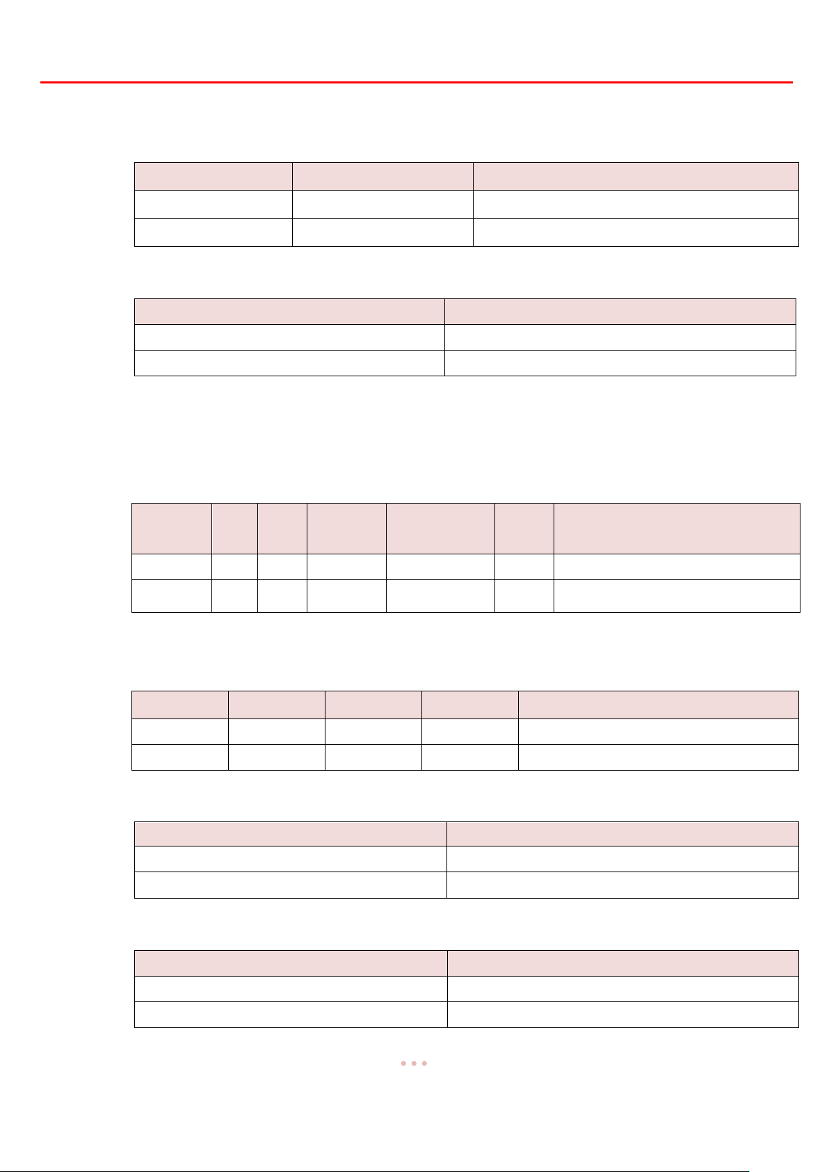
Directive
Group
Ambient Temperature
ATEX II 2 GD
Ex db IIB T4 Gb
- 30 °C to + 70 °C ( - 22 °F to + 158 °F )
ATEX II 2 GD
Ex tb IIIC T130 °C Db
- 30 °C to + 70 °C ( - 22 °F to + 158 °F )
Group
Ambient Temperature
Ex db IIB T4 Gb
- 30 °C to + 70 °C ( - 22 °F to + 158 °F )
Ex tb IIIC T130 °C Db
- 30 °C to + 70 °C ( - 22 °F to + 158 °F )
National
Conformity
Class
Zone
Protection
Method
Groups
T-Code
Ambient Temperature
AEx / Ex
I 1 db
IIB, IIA
T4
- 30 °C to + 70 °C ( - 22 °F to + 158 °F )
AEx / Ex
II
21
tb
IIIC, IIIB, IIIA
T130°C
- 30 °C to + 70 °C ( - 22 °F to + 158 °F )
Class
Division
Groups
T-Code
Ambient Temperature
I 1 C,D
T4
- 30 °C to + 70 °C ( - 22 °F to + 158 °F )
II 1 E,F,G
T130°C
- 30 °C to + 70 °C ( - 22 °F to + 158 °F )
Group
Ambient Temperature
Ex db IIB T4 Gb
- 30 °C to + 70 °C ( - 22 °F to + 158 °F )
Ex tD A21 IP68 T130°C
- 30 °C to + 70 °C ( - 22 °F to + 158 °F )
Group
Ambient Temperature
Ex db IIB T4 Gb
- 30 °C to + 70 °C ( - 22 °F to + 158 °F )
Ex tb IIIC T130°C Db
- 30 °C to + 70 °C ( - 22 °F to + 158 °F )
1.4 Standards
ATEX European Hazardous Area: EN60079-0, EN60079-1, EN60079-31
IECEx International Hazardous Area:IEC 60079-0, IEC 60079-1, IEC60079-31
North American Hazardous Area:
Zone System:
CAN/CSA-C22.2 No. 0-10, CAN/CSA-C22.2 No. 60079-0, CAN/CSA-C22.2 No. 60079-1,
CAN/CSA-C22.2 No. 60079-31, UL 60079-0, UL 60079-1, UL 60079-31
Division System:
CAN/CSA-C22.2 No. 0-10, CSA C22.2 No. 30-M1986, CSA C22.2 No. 25-17,
FM 3600, FM 3615, FM 3616
CNEx Certification:GB3836.1, GB3836.2, GB12476.1, GB12476.5
TS Certification:CNS3376-0, CNS3376-1, IEC60079-31

Explosion-Proof Quarter-Turn Valve Actuator【OME Series】 Sun Yeh Ele. Ind. Co., Ltd. | 2019.07
5
1.5 Inspection, Storage, Transport
1.5.1 Receiving / Inspection
Carefully inspect the package for any damages resulting from shipping and report all
damages to the freight carrier and seller.
After unpacking the product and information packet, please keep the cartons and any
packing materials in case of product return or replacement. Verify that the items listed in
packing slip or in bill of lading are the same as what were ordered. If there is any
discrepancy, please contact the seller.
Verify that the technical data on nameplate is in accordance with what was ordered.
1.5.2 Storage
The actuator should be stored in a dry area with relative humidity of less than 90 %(20 ± 5
°C)and at temperature between -20 °C to + 40 °C (-4 °F to + 104 °F).
The product shall be stored with suitable protection from corrosive substance that can
damage the metal and insulating parts.
The metal plugs for temporary protection should not be removed until the actuator is ready
to be cabled. Use suitable flameproof cable glands to ensure IP rated protection when
installing. Please refer to 1.2.3 (P.3).
1.5.3 Transport
Attach ropes or hooks for the purpose of lifting by hoist only to housing and not to
handwheel.
Actuators packaged in cartons can stand up to land, sea, or air transportation.
Packaged actuators shall avoid of violent impact and strong vibrations and be protected
from rain or snow.
1.5.4 Lubrication
The gear train has been sufficiently lubricated at the factory. No additional lubrication is
required.

Explosion-Proof Quarter-Turn Valve Actuator【OME Series】 Sun Yeh Ele. Ind. Co., Ltd. | 2019.07
6
2 Product Overview
OME series explosion-proof quarter-turn electric actuators offer torque ranges from 35Nm to
1,500Nm ( 310 in.lb to 13,280 in.lb ). Product design is based on a self-locking worm drive principal,
which provides for a smooth running, dependable, robust drive system. All models are ISO 5211 compliant,
have a visual position indicator on top of actuator cover and manual override except OME-A. The manual
operation is non-clutch design that can be operated without any lever, clutch or brake upon power outage.
ATEX / IECEx / CNEx / TS Explosion-proof instructions:
OME series Explosion-proof Quarter-turn Electric Valve Actuator (referred as "actuator") is a
control device for valves and can be used in the places, where is classified as Zone 1 or Zone 2,
contained GroupⅡA and GroupⅡB gases, Zone 21 or Zone 22, contained the combustible dust
atmosphere or the mixture circumstance with the explosive gas atmospheres and the combustible
dust atmospheres. Temperature group T1-T4.
Certificate Number:
Sira17ATEX1243X
IECEx SIR17.0062X
CNEx17.2492X
(ITIR) 2018 No.07-00013
CSA explosion-proof instructions:
Division System where is classified as North American Division 1 or Division 2 of hazardous
location, contains Group C and Group D gases and temperature group T1 - T4; or contains one
or several flammable dusts with minimum flaming point over 130 °C; or include both above
flammable gases and dusts.
Zone System where is classified as North American Zone 1 or Zone 2 of hazardous location,
contains Group ⅡA and Group ⅡB gases and temperature group T1 - T4; or in Zone 21 or
Zone 22, contained one or several flammable dusts with the minimum flaming point over 130
°C; or include both above flammable gases and dusts.
Certificate Number:
70156877
Explosion-Proof Quarter-Turn Valve Actuator【OME Series】 Sun Yeh Ele. Ind. Co., Ltd. | 2019.07
7
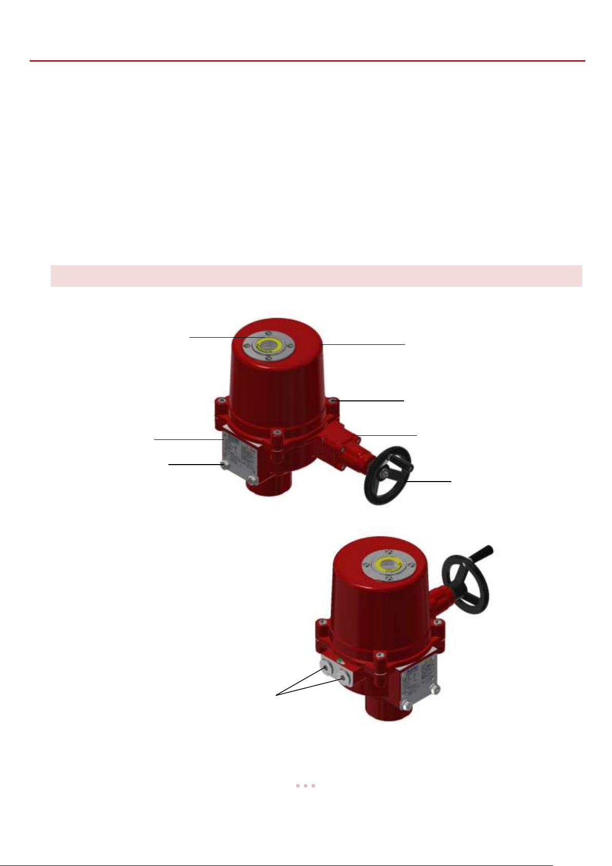
Actuator Top Cover
Top Cover Screw
Position Indicator
Casting End Cap
Handwheel
Nameplate
Mechanical End Stops
Conduit Entries Flamepath Joint
2.1 Features
Enclosure conforms to IP68 (7 m / 72 hrs).
High alloy-steel gear trains with elf-locking prevent back-drive.
Clutch-less manual override.
ISO 5211 mounting flange.
Mechanical end stops.
Flatted position indicator.
Built-in motor thermal protection.
3 Product Mechanical Data
3.1 Parts Identification
Explosion-Proof Quarter-Turn Valve Actuator【OME Series】 Sun Yeh Ele. Ind. Co., Ltd. | 2019.07
8
Model
Torque
Weight
Moto Power
Manual Override
Mounting Flange
Nm
inlb
kg
lb
Watt
ISO 5211
OME-1
35
310
2 4 10
Lever
F03 / F05
OME-AM
50
445
3 7 10
F07
OME-A
50
445
3 7 10
N/A
F07
OME-2
90
800
18
40
40
Handwheel
F07
OME-3
150
1330
18
40
40
F07
OME-4
400
3540
32
71
80
F10
OME-5
500
4430
32
71
80
F10
OME-6
650
5755
32
71
80
F10
OME-7
1000
8855
46
101
120
F12 or F14
OME-8
1500
13280
46
101
120
F12 or F14
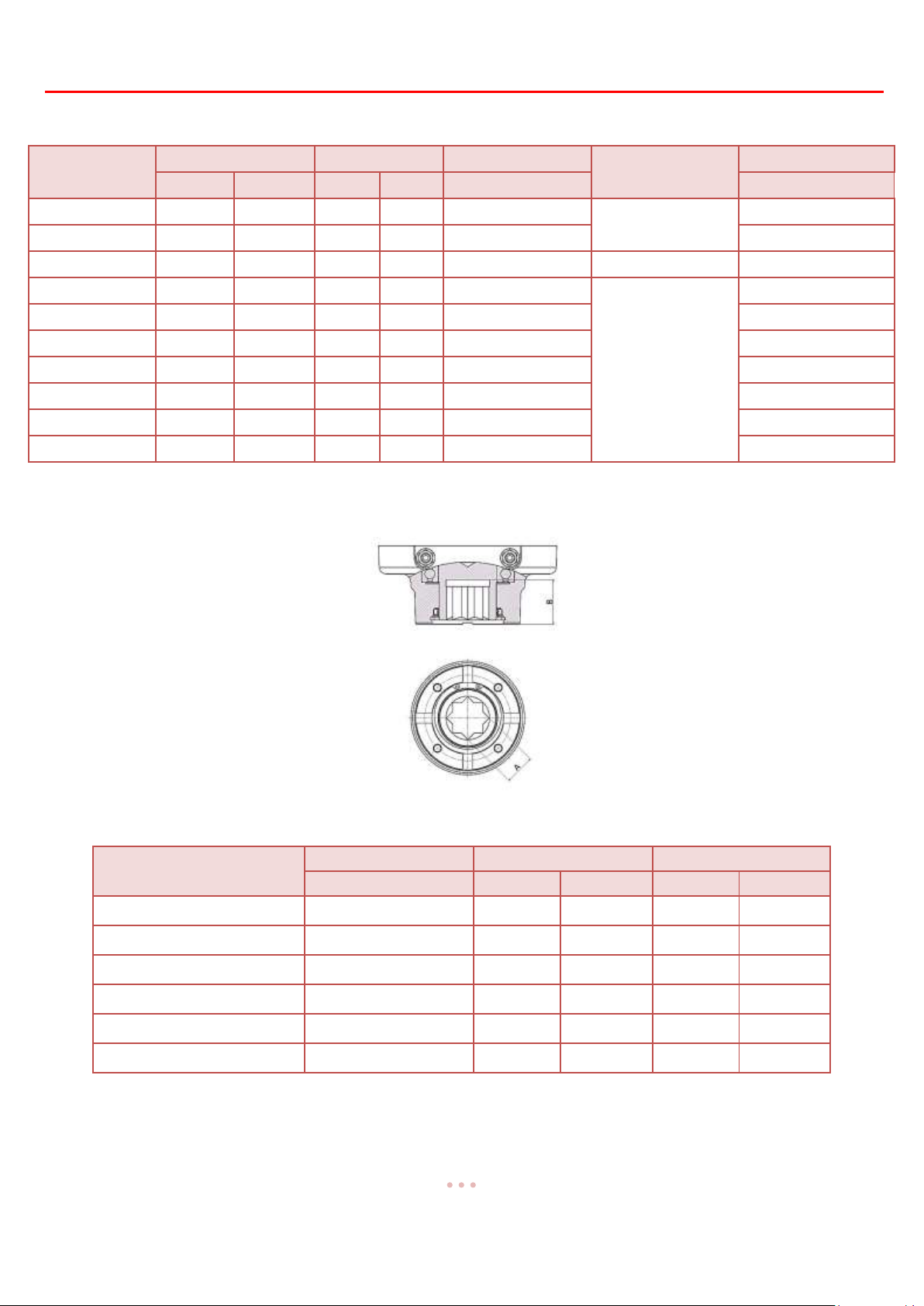
Model
Mounting Flange
Shaft (A)
Depth of Shaft (B)
ISO 5211
mm
inch
mm
inch
OME-1
F03 / F05
14
0.551
17
0.669
OME-A
F07
17
0.669
20
0.787
OME-AM
F07
17
0.669
20
0.787
OME-2 to OME-3
F07
22
0.866
30
1.181
OME-4 to OME-6
F10
36
1.417
48
1.889
OME-7 to OME-8
F12 or F14
36
1.417
50
1.968
3.2 Technical Information
3.3 Mounting Base Details

Explosion-Proof Quarter-Turn Valve Actuator【OME Series】 Sun Yeh Ele. Ind. Co., Ltd. | 2019.07
9
OME- ❶-❷-❸-❹
❶Type
A
AM
1
2
3
4
5
6
7
8
❷Voltage
24 : 24 VAC
D24 : 24 VDC
110 : 110 VAC 1PH
120 : 120 VAC 1PH
220 : 220 VAC 1PH
240 : 240 VAC 1PH
❸Control Mode
F:Floating
M:Modulating
❹Duty cycle
30:30 %
75:75 %
3.4 Actuator Selection
3.5 Sizing
The actuator shall be sized to ensure that its torque output meets the load requirements of valve
and its ability to overcome the required duty cycle of application (As a MINIMUM, a 30% safety
factor is suggested for the calculation of torque requirement).
a.
If the maximum torque of 5” valve is 80 Nm 80 × 1.3 (safety factor) = 104 Nm
104 Nm < 150 Nm (OME-3) OK!
104 Nm > 90 Nm (OME-2) Not OK!
b. In cases where the actuator does not fit directly onto the valve, a mounting kit is required. Please
ensure the bracket and coupling are properly designed and manufactured to withstand the torque
output of the actuator.

Explosion-Proof Quarter-Turn Valve Actuator【OME Series】 Sun Yeh Ele. Ind. Co., Ltd. | 2019.07
10
Running Time (Sec)
Running Time (Sec) + Rest Time (Sec)
Running Time (Sec) x (1- Duty Cycle)
Duty Cycle
3.6 Duty Cycle
The duty cycle is the relationship between the running time and resting time. It is calculated as
below:
Duty Cycle = x100 %
Rest Time (Sec)=
If the running time for OME-2 is 15 sec, 30% duty cycle, the rest (off) time shall be
calculated as below:
15 × [ ( 1–30%) / 30% ] = 35 The rest time will be 35 sec.
If the running time for OME-2 is 15 sec, 75% duty cycle, the rest (off) time shall be
calculated as below:
15 × [ ( 1–75%) / 75% ] = 5 The rest time will be 5 sec.
Note: For higher duty cycles, choose the 75% duty cycle.
One cycle consists of open-rest-close-rest.

Explosion-Proof Quarter-Turn Valve Actuator【OME Series】 Sun Yeh Ele. Ind. Co., Ltd. | 2019.07
11
Model
Screw
Allen Key
Torque
mm
Nm
OME-A, OME-AM & OME-1
M6
5
8
OME-2 to OME-3
M10
8
43
OME-4 to OME-8
M12
10
75
Top Cover
Main Housing
Flamepath Joints
Conduit Entries
Flamepath Joint
O-ring
Explosion-proof
Metal Plug
Top Cover Screw
3.7 Flamepath Joint
During cover removal and conduit entry removal, ensure that surfaces are free from
scratches or scrapes.
Actuator installation and maintenance must be performed by trained personnel.
Flamepath Joint
Cover Romoval
Remove the conduit entry metal plugs to relieve the pressure inside the actuator for the ease of
the top cover removal and gently remove the cover. DO NOT attempt to remove the top cover with a
screwdriver as it will damage the surfaces.
Cover Installation
Please ensure that the O-ring seal is in good condition prior to cover installation. Slowly
re-install the cover while being careful not to pinch the O-ring seal.
The explosion-proof enclosures are labeled with a QA code on both of the middle plate and
the cover, please verify the QA code inside the cover is the same as the one on middle plate
when installation. The cover is not interchangeable.
Please follow this table to tighten the cover screw:

Explosion-Proof Quarter-Turn Valve Actuator【OME Series】 Sun Yeh Ele. Ind. Co., Ltd. | 2019.07
12
❶ Model No.
❷ Running Time
❸ Torque
❹ Enclosure Rating
❺ Motor Power
❻ Supply Voltage
❶
❷
❸
❹
❺
❻
❼
❽
❾
❼ Rated Current
❽ Serial No.
❾ Date of Manufacture
❿ Ambient Temp.
⓫ Waring
ATEX, IECEx and CNEx
TS
❶
❷
❸
❹
❺
❻
❼
❽
❾
⓫
⓫
CSA
❶
❷
❸
❹
❺
❻
❼
❿
❽
❾
⓫
Nameplate indication
3.8 Nameplate Details
Please make sure the explosion-proof specification for the product is consistent with
nameplate and instruction.

Explosion-Proof Quarter-Turn Valve Actuator【OME Series】 Sun Yeh Ele. Ind. Co., Ltd. | 2019.07
13
Min. 2mm
4 Mounting And Setup
4.1 Handwheel Installation
a. Pass the screw through the handle and tighten the nut onto handwheel.
Do not overtighten.
b. Secure the handle to the wheel with the slotted screw and tighten the locknut all the way down to
the wheel. Ensure that the locknut is locked between the wheel and the handle.
Leave a 2mm gap between the locknut and the handle as the figure below to allow the
handle free to rotate and then to have a smooth manual operation.
c. Slide fixing screw through washers and handwheel and secure them to override shaft as shown in
the figure below.
Turn off power when installing
handwheel.
d. Assembly completed as shown in the
figure below.

Explosion-Proof Quarter-Turn Valve Actuator【OME Series】 Sun Yeh Ele. Ind. Co., Ltd. | 2019.07
14
Handwheel
Actuator Driver
4.2 Valve Mounting Instructions
a. Make sure both the valve and actuator are in the same position before mounting, either
fully-open or fully-closed. If not, use the manual override to correct this.
b. Once mounted together, either directly or with a mounting kit, ensure that they are properly
secured together and all fasteners are tightened.
Remove all of valve handle parts, for example, the handle or open/close mechanical
stops so as to not interfere with the actuator.
c. Check again that the valve and actuator are in the same position.
d. Remove the conduit entry plug to relieve the pressure inside the actuator for the ease of the top
cover removal and gently remove the cover, please refer to 3.7 (P.11) for cover installation.
The power must be off before removing the cover.
AFTER DE-ENERGIZING, DELAY 10 MINUTES BEFORE OPENING THE
COVER.
e. Refer to section 4.3 (P.15) for wiring notices and connect the wires according to the wiring
diagram labeled inside the cover of actuator.
f. Supply power to actuator.
Care must be taken at all times as there are live
circuits present that may cause electrical shock.
g. Re-calibration may be required for the end positions, refer to
4.4 (P. 16) for further instructions.
h. For modulating units, refer to 5 (P.21 - P.27) setting
instructions.
Use the insulated wires and length should be less than 30 m.
A minimum of 18 AWG wire is recommended for all field wiring.
Turn power off before changing any settings.
i. Assemble the cover and secure cover screws firmly after setting.
Refer to 3.7 (P.11) for installation and check if there is any foreign object between top
cover flamepath joint and base.
Please ensure that the O-ring seal is in good condition prior to cover installation.
The explosion-proof enclosures are labeled with a QA code on both of the middle plate
and the cover, please verify the QA code inside the cover is the same as the one on
middle plate when installation. The cover is not interchangeable.

Explosion-Proof Quarter-Turn Valve Actuator【OME Series】 Sun Yeh Ele. Ind. Co., Ltd. | 2019.07
15
4.3 Wiring Instructions
Turn power off before making the electrical connecrion!
There are grounding devices both inside and outside of the actuator (green screw) and the ground
wires should be connected properly.
The conduit entries are attached two conduit entries plugged by metal plugs, and the specification
as below. Each actuator is attached with two metal plugs to conduit entries.
OME-A, OME-AM and OME-1: 1/2” NPT, M20.
OME-2 to OME-8: 3/4” NPT, 1/2” NPT, M20, M25.
Use correct size of fittings so as to not damage the threads.
Verify the supply power is in accordance with the data on the nameplate to prevent a short circuit
and an electrical shock.
Do not apply power to actuator before wiring, otherwise it can cause an electrical
shock or damage components of the actuator.
After wiring, please tighten the conduit entries with suitable cable glands and cover properly.
Unused conduit entries have to be sealed with metal plugs to reach explosion- proof function.
Please refer to 1.2.3 (P.3).

Explosion-Proof Quarter-Turn Valve Actuator【OME Series】 Sun Yeh Ele. Ind. Co., Ltd. | 2019.07
16
【Close】
【Open】
Mechanical End Stop
4.4 Actuator Set-up
The power must be off during this procedure so as to avoid damage to the actuator.
Do not make adjustments to the mechanical end stops when actuator is in motion.
All steps below must be completed before normal operation.
The actuators have been set and calibrated at the factory. Most of products will not require
recalibration of these settings. However these are general settings. After valve and actuator are
bolted together, apply power to verify the end positions are correct. If an adjustment is required,
please follow steps below:
4.4.1 Instructions
The travel cams are set to control the open and closed position of the valve. See
below procedure for corresponding actuator model:
OME-1, OME-A and OME-AM:The position is set to stop the travel of the actuator
when the travel cams activate the limit switch.
OME-2 to OME-8:The position is set to stop the travel of the actuator when the
travel cams don’t activate the limit switch.
The standard is with two limit switches (LS1 & LS2).
LS1 & LS2:LS1is for open and LS2 is for close. They limit the fully-open and
fully-closed travel range by disabling the electric motor.
LS3 & LS4 are optional. They allow external equipment to confirm that the valve has
reached the fully-open and fully-closed positions.
4.4.2 Adjustment Steps
a. Turn power off.
b. Loosen the locknut and unwind the mechanical end
stops open and closed screws per below instruction.
OME-2 to OME-6: 25 turns
OME-7 to OME-8: Remove the mechanical
end stop screws completely.

Explosion-Proof Quarter-Turn Valve Actuator【OME Series】 Sun Yeh Ele. Ind. Co., Ltd. | 2019.07
17
Sector Gear
Set Screw M5
Set Screw M5
【OME-1, OME-A and OME-AM】
【OME-2 to OME-8】
c. For modulating units, loosen the M5 set screw on the sector gear or round gear first.
Round Gear
d. Adjust the fully-open position
OME-A is not available for the manual device setting.
1. Use the manual override to turn the valve to the fully-open position.
2. Remove the cover.
OME-1, OME-A and OME-AM: Loosen the M5 set screw of cam TC1 with a 4 mm
Allen Key.
OME-2 to OME-8: Loosen the M3 set screw of cam TC1 with a 2.5 mm Allen Key.
3. Adjust the travel cam based on the corresponding actuator model below:
OME-A and OME-AM
Rotate the cam TC1 clockwise to contact the switch arm.
Slowly rotate the cam TC1 clockwise until a light click is heard.
OME-1
Rotate the cam TC1 counter-clockwise to contact the switch arm.
Slowly rotate the cam TC1 counter-clockwise until a light click is heard.
OME-2 to OME-8
Rotate the cam TC1 counter-clockwise to contact the switch arm.
Slowly rotate the cam TC1 counter-clockwise until a light click is heard.
4. Securely tighten the M5 set screw and apply power to check if the fully-open position is
correct. If it is not correct, please repeat steps 1 to 3.
5. Use the same method to reset the cam TC3.
Adjust cam TC3 so it trips just before cam TC1 does.
6. After the adjustment is completed, check again that the M5 set screw is securely
tightened.
e. Adjust the fully-closed position
1. Use the manual override to turn the valve to the fully-closed position.
2. OME-A, OME-AM and OME-1: Loosen the M5 set screw on switch TC2 with a 4 mm
Allen key.
OME-2 to OME-8: Loosen the M3 set screw of cam TC2 with a 2.5 mm Allen Key.

Explosion-Proof Quarter-Turn Valve Actuator【OME Series】 Sun Yeh Ele. Ind. Co., Ltd. | 2019.07
18
OME-A and OME-AM
TC4 (Optional Item)
TC3 (Optional Item)
Counter-clockwise: decrease closing degree.
Counter-clockwise: increase opening
3. Adjust the travel cam based on the corresponding actuator model below:
OME-A and OME-AM
Rotate the cam TC2 counter-clockwise to contact the switch arm.
Slowly rotate the cam TC2 counter-clockwise until a light click is heard.
OME-1
Rotate the cam TC2 clockwise to contact the switch arm.
Slowly rotate the cam TC2 clockwise until a light click is heard.
OME-2 to OME-13
Rotate the cam TC2 clockwise to contact the switch arm.
Slowly rotate the cam TC2 clockwise until a light click is heard.
4. Securely tighten the M5 set screw and apply power to check if the fully-closed position
is correct. If it is not correct, please repeat steps 1 to 3.
5. Use the same method to reset the cam TC4.
Adjust cam TC4 so it trips just before cam TC2 does.
6. After the adjustment is completed, check again that the M5 set screw is securely
tightened.
TC2 “CLOSE”
Clockwise: increase closing degree.
TC1 “ OPEN”
Clockwise: decrease opening degree.

Explosion-Proof Quarter-Turn Valve Actuator【OME Series】 Sun Yeh Ele. Ind. Co., Ltd. | 2019.07
19
OME-1
OME-2 to OME-8
TC4 (Optional Item)
TC3 (Optional Item)
Counter-clockwise: increase closing degree.
Counter-clockwise: decrease opening
TC4 (Optional Item)
TC3 (Optional Item)
Counter-clockwise: increase closing degree.
Counter-clockwise: decrease opening
TC2 “CLOSE”
TC1 “ OPEN”
Clockwise: decrease closing degree.
Clockwise: increase opening degree.
TC2 “CLOSE”
TC1 “ OPEN”
Clockwise: decrease closing degree.
Clockwise: increase opening degree.

Explosion-Proof Quarter-Turn Valve Actuator【OME Series】 Sun Yeh Ele. Ind. Co., Ltd. | 2019.07
20
OME-A and OME-AM
Rotate the round gear counter-clockwise to
the end and tighten the M5 set screw.
OME-1
Rotate the round gear clockwise to the end
and tighten the M5 set screw.
OME-2 to OME-8
Rotate the sector gear clockwise to the end
and tighten the M5 set screw.
Round Gear
M5 Set Screw
Sector Gear
【OME-1, OME-A and OME-AM】
【OME-2 to OME-8】
f. Supply the power and unwind the mechanical end stop screws to the fully-open position
based on the actuator model listed below:
Do not remove the cover to supply power if the actuator is located in a hazardous
environment. If so, for the following steps, operate the unit manually.
OME-2 to OME-3:1 turn.
OME-4 to OME-8:1/2 turn.
g. Tighten the locknut.
h. Supply the power and unwind the mechanical end stop screws to the fully-closed position
based on the actuator model listed below:
OME2 to OME-3:1 turn.
OME4 to OME-8:1/2 turn.
i. Tighten the locknut of mechanical end stops.
j. Confirm that the limit switches achieve the full open-close stroke.
k. Modulating units:
After completing the fully-open and fully-closed calibration, run the actuator to the
fully-closed position, and then adjust the gear and the set screws as the steps below
according to the corresponding actuator model.
M5 Set Screw
l. The setting procedure is now completed.

Explosion-Proof Quarter-Turn Valve Actuator【OME Series】 Sun Yeh Ele. Ind. Co., Ltd. | 2019.07
21
Σ
Controller
Motor
Driver
Feedback
Signal
Motor
Gear Box
-
e
+
Input Signal
Output
Signal
OME-1, OME-A and OME-AM
OME-2 to OME-8
1 2 4 5 6 7
11 12
A
B
1
2
3
6
7
8
9
10
11
12
5 Modulating Control Board Adjustment
5.1 Modulating Control Board Surface
The layout is based on 110/220VAC voltage.
5.2 Procedure

Explosion-Proof Quarter-Turn Valve Actuator【OME Series】 Sun Yeh Ele. Ind. Co., Ltd. | 2019.07
22
Input Signal
State of Switches
4 - 20 mA
1 at ON, 2 at OFF
1 - 5 V
1 at OFF, 2 at OFF
2 - 10 V
1 at OFF, 2 at ON
1 2 3 4 5 6 7
8
Factory Setting
ON
OFF
OFF
ON
OFF
OFF
OFF
ON
4 - 20 mA input
ON
OFF
1 - 5 V input
OFF
OFF
2 - 10 V input
OFF
ON
4 - 20 mA output
OFF
ON
OFF
2 - 10 V output
ON
OFF
ON
Input 20 mA / 5 V / 10 V to operate valve to fully-open position
OFF
Input 20 mA / 5 V / 10 V to operate valve to fully-closed position
ON
When signal input failed, driving valve to fully-open (when S6 sets at “ ON”).
OFF
ON
When signal input failed, driving valve to fully-closed (when S6 sets at “ ON”).
ON
OFF
When signal input failed, driving valve to fully-closed (when S6 sets at “ OFF”).
OFF
ON
When signal input failed, driving valve to fully-open (when S6 sets at “ OFF”).
ON
OFF
When signal input failed, valve stays at the last position.
ON
ON
Please follow steps below if an adjustment of these settings are required. Please restart
the actuator after adjusting.
5.3 Dip Switch Setting (SW1)
The Dip Switch SW1 is a combination of 8 switches and equally divided in two rows. It is
utilized to select signal type of input as well as output and fail positioning when the signal input fails.
The sliders can be placed at either ON (upper) or OFF (lower) state position. Factory settings are
switches 1, 4, 8 at ON state and switches 2, 3, 5, 6, 7 at OFF state.
a. Input Signal Setting (1 - 2)

Explosion-Proof Quarter-Turn Valve Actuator【OME Series】 Sun Yeh Ele. Ind. Co., Ltd. | 2019.07
23
Output Signal
State of Switches
4 - 20 mA
3 at OFF, 4 at ON, 5 at OFF
2 - 10V
3 at ON, 4 at OFF, 5 at ON
Input Signal
Fully-Open ( 90°)
Fully-Closed ( 0° )
4 - 20 mA
4 mA
20 mA
1 - 5 V
1 V
5 V
2 - 10 V
2 V
10 V
b. Output Signal Setting (3 - 5)
c. Setting of fail position when signal input failed (Switches 6 - 8)
The input signal type is set by switches 1 and 2. And switch 6 is used to set the
corresponding relationship between value of signal input and operation direction of
actuator.
When S6 is set to ON:
The program defines 20 mA or 5 V or 10 V as a command for fully-closed positioning. The
line graph below shows the signal level and the corresponding position of actuator.
When a low signal value is received, the actuator operates toward fully-open position and
when a high signal value is received, the actuator operates toward fully-closed position.

Explosion-Proof Quarter-Turn Valve Actuator【OME Series】 Sun Yeh Ele. Ind. Co., Ltd. | 2019.07
24
Fail Position
State of Switch
Fully-Open ( 90°)
7 at OFF, 8 at ON
Fully-Closed ( 0° )
7 at ON, 8 at OFF
The Last Position
7 at ON, 8 at ON
Input Signal
Fully-Open ( 90°)
Fully-Closed ( 0°)
4 - 20 mA
20 mA
4 mA
1 - 5 V
5V
1V
2 - 10 V
10V
2V
Signal Failed Position
Setting of Switch
Fully-Open ( 90°)
7 at ON, 8 at OFF
Fully-Closed ( 0°)
7 at OFF, 8 at ON.
The Last Position
7 at ON, 8 at ON.
The selection of the fail position while the input signal failed, please follow table below:
When S6 is set to OFF
The program defines 20 mA / 5 V /10 V as a command for fully-open positioning. The line
graph below shows the signal level and the corresponding position of the actuator.
When a high signal value received, the actuator operates toward fully-open position and when
a low signal value received, the actuator operates toward fully-closed position.
he selection of the fail position while the input signal failed, please follow table below:

Explosion-Proof Quarter-Turn Valve Actuator【OME Series】 Sun Yeh Ele. Ind. Co., Ltd. | 2019.07
25
Variable Resistor
Signal type to be adjusted
Position to be adjusted
VR1
To adjust 10 V, 20 mA signal input
Fully-Open
VR51
To adjust 10 V, 20 mA signal output
Fully-Open
VR2
To adjust 2 V, 4 mA signal input
Fully-Closed
VR52
To adjust 2 V, 4 mA signal output
Fully-Closed
VR51
VR52
VR1
VR2
LDR
LDG
7 1 2 4 5 6 11
12
5.4 Sensitivity Switch Setting (SW2)
Original factory setting is “3”.
When switched to “1”: The Highest Sensitivity and the 0 - 90 degree travel is divided up to
around 50 movements.
When switched to “0”: The Lowest Sensitivity and the 0 - 90 degree travel is divided up to around
10 movements.
5.5 Settings for OPEN and CLOSE
These settings are set and calibrated at the factory. Mostly, they do not need to be
recalibrated. Please follow steps below to set when required.
OME-1, OME-A and OME-AM
Use a multimeter to measure the output signal in accordance with the selected signal type.
VR1, VR51, VR2 and VR52 are used to adjust signal input as well as output.l.
If VR51 and VR52 are adjusted, VR1 and VR2 must be adjusted accordingly.

Explosion-Proof Quarter-Turn Valve Actuator【OME Series】 Sun Yeh Ele. Ind. Co., Ltd. | 2019.07
26
LD1
Fully-closed
LD6
Motor thermal protector started
LD2
Fully-open
LD7
Output signal short circuit
LD3
Power
LD8
Overcurrent in motor
LD4
Abnormal voltage input
LD9
Local setting mode
LD5
Wrong Input Signal
LD1~9
MODE
SET
DN
UP
VR2
1
2
3
4
5
6
7
8
9
10
11
12
VR51
Clockwise: decreasing signal value.
Counter-clockwise: increasing signal value.
VR52
Clockwise: decreasing signal value.
Counter-clockwise: increasing signal value.
Fully-OPEN setting
Rotate VR1 counter-clockwise until a light click is heard, then apply 10V or 20mA to the
modulating board. After that, slightly rotate VR1 clockwise until the LDR goes on and then
adjust VR51 to complete the setting. When adjusting VR51, if the green light is off, keep
rotating VR1 clockwise until the green light goes on.
Fully-CLOSE setting
Rotate VR2 clockwise until a light click is heard, then apply 2 V or 4 mA to the modulating
board. After that, slightly rotate VR2 counter-clockwise until the LDR goes on and then
adjust VR52 to complete the setting. When adjusting VR52, if the red light is off, keep
rotating VR2 counter-clockwise until the red light goes on.
OME-2 to OME-8
Using UP, DN, MODE, SET buttons to set the open and close position.
Press and hold ”SET” switch for 2 seconds until LD 9 lights to enter local setting mode.

Explosion-Proof Quarter-Turn Valve Actuator【OME Series】 Sun Yeh Ele. Ind. Co., Ltd. | 2019.07
27
VR2
Clockwise: decreasing signal value.
Counter-clockwise: increasing signal value.
Fully-OPEN setting
a. Press and hold “UP” switch to operate the actuator to open until it has reached
fully-open position and LD2 lights and then input a signal 5 V or 10 V or 20 mA.
b. Press “MODE” switch for 2 seconds to complete the setting of fully-open position.
Fully-CLOSED setting
a. Press and hold “UP” switch to operate the actuator to open until it has reached
fully-closed position and LD2 lights and then input a signal 1 V or 2 V or 4 mA.
b. Press “MODE” switch for 2 seconds to complete the setting of fully-closed position.
See below description for VR2 adjustment:
After completing the above settings, press “SET” switch to quit local setting.

Explosion-Proof Quarter-Turn Valve Actuator【OME Series】 Sun Yeh Ele. Ind. Co., Ltd. | 2019.07
28
Status of LEDs
Possible problems
Solution
LD3 does not go on
a. No power supplied.
b. Incorrect connection of the
lines #8, #9 of potentiometer.
c. Modulating controller failed.
a. Check the power supply as well as wires
connected to terminals #4 & #5, please
refer to 5 (P.21)
b. Verify the actuator is wired properly as
per wiring diagram.
c. Send back to factory for inspection.
LD4 goes on
(for 24V units)
The voltage is under 20.4V.
Verify that the input voltage is within the
allowable voltage deviation.
LD5 goes on
a. An incorrect signal type
inputted. For example, preset
with 2-10 V input but input
4-20 mA.
Or preset with 4 - 20 mA
input but input 2 - 10V
signal. In this case, the
actuator still works in 2 - 7V.
When the signal is over 7.2
V, the LD5 lights.
b. Input a voltage exceeding the
rated. For example, preset
with 2-10 V input but input
13.5V.
Verify if the switch 1 is set in accordance
with the type of input signal. Please refer to
5.3 (P.22 - P.24).
LD6 goes on
Motor thermal protector started.
a. The duty cycle exceeded the rated,
please refer to 3.5 (P.9).
b. The contact of motor thermal protector
(MOT) disconnected.
LD7 goes on
a. Signal output short circuits.
b. The input signal type 2 - 10 V
with reversed polarity.
a. Verify if the signal output with reversed
polarity. The negative pole should be
connected to terminal #11 and the
positive pole should be connected to
terminal #12.
b. Verify if the signal input with reversed
polarity when applying 2 - 10V, the
negative pole should be connected to
terminal #6 and the positive pole should
be connected to terminal #7.
5.6 Troubleshooting of modulating controller
In case LD3 does not light or any of LD4 to LD9 lights when the actuator is motorized,
please refer to steps below for basic troubleshooting.

Explosion-Proof Quarter-Turn Valve Actuator【OME Series】 Sun Yeh Ele. Ind. Co., Ltd. | 2019.07
29
LD8 goes on
Motor over-current.
a. Duty cycle exceeded the rated, please
refer to 3.6 (P.10) and reduce the duty
rating.
b. Check the load.
c. Check if the motor rotor is locked (For
example: Valve is stuck by foreign
objects).
LD9 goes on
Local setting mode - Setting
position for open & close.
After completing setting, press
“SET” button to quit.
After completing the settings, press “SET”
switch to quit.

Explosion-Proof Quarter-Turn Valve Actuator【OME Series】 Sun Yeh Ele. Ind. Co., Ltd. | 2019.07
30
Possible problems
Solution
a. The limit switch for fully-closed does not
trip.
b. Motor shaft or bearing were stuck.
c. Power applied to terminals #3 and #4
simultaneously (Parallel Connection).
d. Jammed pipe or valve seat stuck.
e. The seating torque of valve increased
caused by oxidized seals and has resulted
in a torque overload on actuator.
a. Operate the actuator manually to
fully-closed position and confirm if the
limit switch trips.
b. Replace them.
c. If the parallel connection is required,
follow the wiring diagram inside the cover
to connect wires or using isolation relays.
d. Check if any blockage or obstacle in pipe
and remove.
e. Manual operate or replace the valve.
Possible problems
Solution
a. The mechanical stop screws ran into the
output drive gearing.
b. A torque overload caused by the valve.
c. Wrong power supply.
d. Supply voltage was too high or too low,
out the tolerance of deviation.
e. Actuator operates too frequently and
exceeded duty cycle rating.
a. Reset the mechanical end stops and travel
cams, please refer to 4.4.2 (P.16 - P.20).
b. This problem happened frequently after
valve operating for a long time. It is
suggested to replace with a new valve.
c. Check the power supply.
d. Check if the operating current values are
higher than the rated values.
e. Adjust the system bandwidth or reduce the
frequency of operation, please refer to 3.6
(P.10).
Possible problems
Solution
Parallel connection.
Check operating current values and install a
relay respectively.
6 Troubleshooting
Floating Controller
Motor does not operate or overheats
The actuator operates but the motor is hot.
To control two or more actuators, sometimes the actuator works abnormally and the motor is
getting hot.

Explosion-Proof Quarter-Turn Valve Actuator【OME Series】 Sun Yeh Ele. Ind. Co., Ltd. | 2019.07
31
Possible problems
Solution
a. The actuator is not properly installed onto
the valve.
b. The set screw of the cam loosened and
resulted in that the travel end positions
misaligned.
c. The torque of valve is larger than the
torque of actuator.
d. The actuator was mounted to the valve
improperly.
a. Contact technical department to solve the
problem.
b. Readjust the mechanical end stops and
limit switches, please refer to 4.4.2 ( P.16 P.20).
c. Replace with a new valve or a larger size
actuator.
d. Disassemble the actuator from the valve
and reassemble them to verify that they are
installed properly.
Possible problems
Solution
a. Blown fuse.
b. PCB board failed.
c. Wrong supply voltage.
a. Send back to factory for inspection.
b. Send back to factory for inspection.
c. Send back to factory for inspection.
Possible problems
Solution
Worked in an environment out of the
withstandable temperature range.
Please use the capacitor at temperature
between -30 °C to +65 °C (-22 °F to +149 °F).
The valve does not operate no matter under either electrical operation or manual operation.
When power is on, LED indicators did not function.
The capacitor is failed.

Explosion-Proof Quarter-Turn Valve Actuator【OME Series】 Sun Yeh Ele. Ind. Co., Ltd. | 2019.07
32
Solution
Please refer to 5.6 (P.23 - P.24).
Possible problems
Solution
The input signal with a reversed polarity, it
means a signal failure.
Verify if the negative pole of signal input
connected to terminal #6 and the positive pole
connected to terminal #7.
Possible problems
Solution
a. Potentiometer failed.
b. The sector gear of potentiometer
loosened.
c. Input wrong signal type.
d. Modulating board failed.
a. Replace with a new potentiometer.
b. Remove the input signal wires and operate
the actuator to fully-closed. And then
recalibrate VR, please refer to 4.4.2-k
(P.20).
c. Check if the input signal is correct, please
refer to 5.3 (P.22).
d. Send back to factory for inspection.
Modulating Controller
The LED indicators (LD4 - LD9) flash.
The LED indication functions properly but the actuator could operate to fully-open as well as
fully-closed, modulating control was out of function.
Modulating control was out of function.

Explosion-Proof Quarter-Turn Valve Actuator【OME Series】 Sun Yeh Ele. Ind. Co., Ltd. | 2019.07
33
7 Warranty
Sun Yeh Ele. Co. Ltd warrants that for a period of twelve months from the date of manufacture it will
either repair or replace, at its option, any of its products which prove to be defective in material or
workmanship. This warranty does not cover damage resulting from causes such as abuse, misuse,
modification or tampering by users. This warranty is extended only to the immediate purchaser of the
Sun Yeh product and is not transferable. To obtain service under this warranty, the purchaser must first
acquire a return authorization from Sun Yeh. Products must be returned to Sun Yeh under freight prepaid.
This warranty is in lieu of all other obligations, liabilities or expressed warranties. Any implied
warranties, including any implied warranty of merchantability are hereby expressly excluded. In no
event shall Sun Yeh be liable for special, incidental or consequential damages arising in connection with
the use of its products, or for any delay in the performance of this warranty due to cause beyond its
control.

Explosion-Proof Quarter-Turn Valve Actuator【OME Series】 Sun Yeh Ele. Ind. Co., Ltd. | 2019.07
34
 Loading...