

Sunx SF4B-F23-01, SF4B-F31-01, SF4B-F39-01, SF4B-F56-01, SF4B-F47-01 Instruction Manual
...
SUNX Limited MJE-SF4B01 No.0005-03V
f
r
Conforming to the examination o
Japanese Ministry of Health, Labo
and Welfare.
Model Examination No. TA347
- 1 -

(MEMO)
- 2 -
SUNX Limited MJE-SF4B01 No.0005-03V

Thank you for purchasing SUNX’s Light Curtain,
SF4B- -01
(hereinafter called ‘this device’).
Please read this instruction manual carefully and thoroughly for the correct and optimum use
of this product.
Kindly keep this manual in a convenient place for quick reference.
This device is a light curtain for protecting a person from dangerous parts of a machine which
can cause injury or accident.
This manual has been written for the following personnel who have undergone suitable
training and have knowledge of light curtains, as well as, safety systems and standards.
who are responsible for the introduction of this device
who design the system using this device
who install and connect this device
who manage and operate a plant using this device
Notes
1) All the contents of this instruction manual are the copyright of the publishers, and may
not be reproduced (even extracts) in any form by any electronic or mechanical means
(including photocopying, recording, or information storage and retrieval) without permission in writing from the publisher.
2) The contents of this instruction manual may be changed without prior notice for further
improvement of the product.
3) Though we have carefully drawn up the contents of this instruction manual, if there are
any aspects that are not clear, or any error that you may notice, please contact our
local SUNX office of the nearest distributor.
SUNX Limited MJE-SF4B01 No.0005-03V
- 3 -

Contents
Chapter 1 Introduction······················································· 6
1-1 Attention Marks ········································································6
1-2 Safety Precautions ···································································6
1-3 Applicable Standards / Regulations··········································9
1-4 Confirmation of Packed Contents···········································10
Chapter 2 Before Using This Device······························· 11
2-1 Features·················································································11
2-2 Part Description ·····································································11
2-3 Protection Area ······································································14
2-3-1 Sensing Area·············································································14
2-3-2 Safety Distance ·········································································15
2-3-3 Influence of Reflective Surfaces ···············································21
2-3-4 Sensor Placement·····································································22
2-4 Mounting ················································································23
2-4-1 Mounting of the Mounting Bracket ············································23
2-4-2 Mounting of the Bottom Cap Cable (optional) ··························28
2-4-3 Extension and Dismantling of Sensor (Series Connection)······30
2-4-4 Mounting of the Cable Protective Tube·····································32
2-5 Wiring ····················································································33
2-5-1 Power Supply Unit·····································································33
2-5-2 I/O Circuit Diagrams and Output Waveform ·····························34
2-5-3 Wiring
2-5-4 Basic Wiring ··············································································39
2-5-5 Wiring for Manual Reset (Interlock is Valid)······························41
2-5-6 Series Connection·····································································43
2-5-7 Parallel Connection ···································································45
2-5-8 Series and Parallel Mixed Connection······································48
2-5-9 Wiring for Auto-reset (Interlock is Invalid)·································51
2-5-10 Wiring Configuration for Invalid External Device
2-5-11 Connection Configuration for Valid Muting Function ················55
2-6 Adjustment ·············································································57
2-6-1 Beam-axis Alignment ································································57
2-6-2 Operation Test···········································································59
2-6-3 Operation···················································································60
㨯
Connecting Procedure and Connector Pin
Arrangement··············································································37
Monitor Function ·······································································53
Chapter 3 Functions························································· 67
3-1 Self-diagnosis Function··························································67
3-2 Interlock Function···································································67
3-3 Emission Halt Function ··························································68
3-4 Interference Prevention Function ···········································68
3-5 Auxiliary Output (Non-safety Output) ·····································69
3-6 External Device Monitor Function ··········································69
3-7 Muting Function ·····································································70
3-8 Override Function ··································································74
SUNX Limited MJE-SF4B01 No.0005-03V
- 4 -

Chapter 4 Maintenance···················································· 76
4-1 Daily Inspection ····································································· 76
4-2 Periodic Inspection (Every Six Months) ································· 77
4-3 Inspection after Maintenance ················································ 78
Chapter 5 Troubleshooting ············································· 79
5-1 Troubleshooting of Emitter····················································· 79
5-2 Troubleshooting of Receiver·················································· 81
Chapter 6 Specifications · Dimensions ·························· 83
6-1 Specifications ········································································ 83
6-2 Options ·················································································· 86
6-3 Dimensions············································································ 92
6-3-1 Rear Mounting with Standard Mounting Bracket (
6-3-2 Side Mounting with Standard Mounting Bracket (
6-3-3 Rear Mounting with Dead Zoneless Mounting
Bracket (
6-3-4 Side Mounting with Dead Zoneless Mounting
Bracket (
6-3-5 Mounting Brackets···································································· 96
MS-SFB-3
MS-SFB-3
)································································· 94
)································································· 95
MS-SFB-1
MS-SFB-1
)· 92
)·93
Chapter 7 Others······························································ 99
7-1 Glossary ················································································ 99
When this device is used as safety equipment for press machines in Japan, be sure to familiarize yourself with the following.
Chapter 1 1-2 Safety Precautions··································································6, 8
Chapter 1 1-3 Applicable Standards / Regulations ········································9, 10
Chapter 2 2-2 Part Description ······································································12
Chapter 2 2-3 Protection Area ·······································································19, 20
Chapter 2 2-4 Mounting ·················································································23, 28, 29, 31, 32
Chapter 2 2-5 Wiring······················································································37
Chapter 2 2-6 Adjustment ··············································································59
Chapter 3 3-7 Muting Function ······································································72
Chapter 4 4-1 Daily Inspection ······································································77
Chapter 6 6-1 Specifications ··········································································83, 84
Chapter 6 6-2 Options ···················································································88, 90
Chapter 6 6-3 Dimensions ·············································································92, 93, 94, 95
SUNX Limited MJE-SF4B01 No.0005-03V
- 5 -
Chapter 1 Introduction
1-1
Attention Marks
This instruction manual employs the following attentions marks , depending on the degree of the danger to call operator’s attention to each particular action.
Read the following explanation of these marks thoroughly and observe these notices without
fail.
If you ignore the advice with this mark, death or serious injury could result.
If you ignore the advice with this mark, injury or material damage could
result.
<Reference>
1-2
Safety Precautions
Use this device as per its specifications. Do not modify this device since its functions and
capabilities may not be maintained and it may malfunction.
This device has been developed / produced for industrial use only.
Use of this device under the following conditions or environment is not presupposed.
Please consult us if there is no other choice but to use this device in such an environment.
1) Operating this device under conditions and environment not described in this manual.
2) Using this device in the following fields: nuclear power control, railroad, aircraft,
automobiles, combustion facilities, medical systems, aerospace development, etc.
When this device is to be used for enforcing protection of a person from any danger occurring around an operating machine, the user should satisfy the regulations established
by national or regional security committees (Occupational Safety and Health Administration: OSHA, the European Standardization Committee, etc.). Contact the relative organization(s) for details.
In case of applying this device to particular equipment, follow the safety regulations in
regard to appropriate usage, mounting (installation), operation and maintenance. The
users including the installation operator are responsible for the introduction of this device.
Use this device by installing suitable protection equipment as a countermeasure for failure, damage, or malfunction of this device.
Before using this device, check whether the device performs properly with the functions
and capabilities as per the design specifications.
In case of disposal, dispose this device as industrial waste.
It gives useful information for better use of this device.
When using this device as safety equipment for press machines in Japan, be sure to use the
device in combination with cable with protective tube (
- 6 -
SFPB-
) (optional).
SUNX Limited MJE-SF4B01 No.0005-03V
Machine designer, installer, employer and operator
The machine designer, installer, employer and operator are solely responsible to ensure that all applicable legal requirements relating to the installation and the use in any
application are satisfied and all instructions for installation and maintenance contained
in the instruction manual are followed.
Whether this device functions as intended to and systems including this device comply
with safety regulations depends on the appropriateness of the application, installation,
maintenance and operation. The machine designer, installer, employer and operator
are solely responsible for these items.
Engineer
The engineer would be a person who is appropriately educated, has widespread
knowledge and experience, and can solve various problems which may arise during
work, such as a machine designer, or a person in charge of installation or operation etc.
Operator
The operator should read this instruction manual thoroughly, understand its contents,
and perform operations following the procedures described in this manual for the correct operation of this device.
In case this device does not perform properly, the operator should report this to the
person in charge and stop the machine operation immediately. The machine must not
be operated until correct performance of this device has been confirmed.
Environment
Do not use a mobile phone or a radio phone near this device.
If there exists a reflective surface in the place where this device is to be installed, make
sure to install this device so that reflected light from the reflective surface does not
enter into the receiver, or take countermeasures such as painting, masking, roughening, or changing the material of the reflective surface, etc. Failure to do so may cause
the sensor not to detect, resulting in death or serious injury.
Do not install this device in the following environments.
1) Areas exposed to intense interference (extraneous) light such as direct sunlight
2) Areas with high humidity where condensation is likely to occur
3) Areas exposed to corrosive or explosive gases
4) Areas exposed to vibration or shock of levels higher than that specified
5) Areas exposed to contact with water
6) Areas exposed to too much steam or dust
7) Areas where the beam-receiving part of this device is directly exposed to light from
high-frequency fluorescent lamp (inverter type) or rapid starter fluorescent lamp.
Installation
Always keep the correctly calculated safety distance between this device and the
dangerous parts of the machine.
Install extra protection structure around the machine so that the operator must pass
through the sensing area of this device to reach the dangerous parts of the machine.
Install this device such that some part of the operator’s body always remains in the
sensing area when operator is done with the dangerous parts of the machine.
Do not install this device at a location where it can be affected by wall reflection.
When installing multiple sets of this device, connect the sets and, if necessary, install
some barriers such that mutual interference does not occur.
Do not use this device in a reflective configuration.
The corresponding emitter and receiver must have the same serial No. and be correctly oriented.
SUNX Limited MJE-SF4B01 No.0005-03V
- 7 -
Equipment in which this device is installed
When this device is used in the ‘PSDI Mode’, an appropriate control circuit must be
configured between this device and the machinery. For details, be sure to refer to the
standards or regulations applicable in each region or country.
Do not install this device with a machine whose operation cannot be stopped immediately in the middle of an operation cycle by an emergency stop equipment.
This device starts the performance after 2 seconds from the power ON. Have the
control system started to function with this timing.
Wiring
Be sure to carry out the wiring in the power supply off condition.
All electrical wiring should conform to the regional electrical regulations and laws.
The wiring should be done by engineer(s) having the special electrical knowledge.
Do not run the sensor cable together with high-voltage lines or power lines or put them
together in the same raceway.
In case of extending the cable of the emitter or the receiver, each can be extended up
to 50m by using the exclusive cable. Furthermore, if the cable is extended in the state
that the sensor is in series connection, or the muting lamp is used, the total extendable
length of the cable depends on the number of the sensors in series connection.
For details, refer to ‘
rangement
Do not control the device only at one control output (OSSD 1, OSSD 2).
Maintenance
When replacement parts are required, always use only genuine supplied replacement
’.
2-5-3 Wiring㨯Connecting Procedure and Connector Pin Ar-
parts. If substitute parts from another manufacturer are used, the sensor may not come
to detect, result in death or serious body injury.
The periodical inspection of this device must be performed by an engineer having the
special knowledge.
After maintenance or adjustment, and before starting operation, test this device following the procedure specified in ‘
Clean this device with a clean cloth. Do not use any volatile chemicals.
Others
Never modify this device. Modification may cause the sensor not to detect, resulting in
Chapter 4 Maintenance
’.
death or serious body injury.
Do not use this device to detect objects flying over the sensing area.
Do not use this device to detect transparent objects, translucent objects or objects
smaller than the specified minimum sensing objects.
When using this product as safety equipment for press machines in Japan, do not use this
device with press machines that do not satisfy the following specifications.
Item Specifications
Model
Pressure capacity 50,000kN or less
Sudden stop time 500ms or less
Stroke length (Within protective height and slide adjustment range)
Range of die size Within bolster width
- 8 -
Press machine having sudden stop device and restart
Prevention mechanism
SUNX Limited MJE-SF4B01 No.0005-03V
1-3
e
e
r
Applicable Standards / Regulations
This device complies with the following standards / regulations.
<EU Directives>
EU Machinery Directive 98/37/EC, EMC Directive 89/336/EEC
<European Standards>
EN 61496-1 (Type 4), EN 55011, EN 954-1 (Category 4)
<International Standards>
IEC 61496-1/2 (Type 4)
<Japanese Industrial Standards (JIS)>
JIS B 9704-1/2 (Type 4), JIS B 9705-1 (ISO 13849-1) (Category 4)
<Standards in U.S. / Canada)>
UL 61496-1/2 (Type 4), UL 1998, CSA C22.2 No.14, CSA C22.2 No.0.8
<Regulations in U.S.>
OSHA 1910.212, OSHA 1910.217(C), ANSI B11.1 to B11.19, ANSI/RIA 15.06
Regarding EU Machinery Directive, a Notified Body, UL International Demko A/S, has certified with the type examination certificate.
With regard to the standards in US / Canada, a NRTL, UL (Underwriters Laboratories Inc.)
has certified for Canada-U.S. Listing.
<Reference>
The conformity to JIS, OSHA and ANSI for this device has been evaluated by ourselves.
The C-CL US Listing Mark
This device conforms to the EMC directive and the Machinery directive. The
body indicates that this product conforms to the EMC directive.
indicates compliance with both Canadian and U.S. requirements.
mark on the sensor main
<Regulations in Japan>
Standards for press machine or shears safety equipment structure
(Ministry of Health, Labor and Welfare Notice No.102, issued September 21, 1978)
This product satisfies the ‘Model Examination’ as set forth in the Japanese Industrial Safety
and Health Laws Provision 44-2 as indicated below.
When this device is used as safety equipment for press machines, be sure to use th
cable with protective tube (
(
SFPB-
) (optional) is not used, this device cannot be used as safety equipment fo
press machines.
SFPB-
) (optional). If the cable with protective tub
<When using this device on its own>
Model Examination No.: No.TA347
Conforming Standards: Standards for press machine or shear safety equipment structure
(Ministry of Health, Labor and Welfare Notice No.102, issued September 21, 1978)
* No.TA347 is a Model Examination No. for this device only.
Up to three sets (maximum number of the beam channel: 192 beam channels) can be
connected in series connection.
* The Model Examination No.TA347 is indicated on the device.
SUNX Limited MJE-SF4B01 No.0005-03V
- 9 -
<When using this device in combination with the control unit SF-C11>
Model Examination No.: No.TA348
Conforming Standards: Standards for press machine or shear safety equipment structure
(Ministry of Health, Labor and Welfare Notice No.102, issued September 21, 1978)
* No.TA348 is a Model Examination No. for the combination of the
SF-C11
and this device.
Up to three sets (maximum number of the beam channel: 192 beam channels) can be
connected in series connection.
* The Model Examination No.TA348 is indicated on
(The Model Examination No.TA347 is indicated on this device.)
SF-C11
.
<When using this device in combination with the control unit SF-C13>
Model Examination No.: No.TA349
Conforming Standards: Standards for press machine or shear safety equipment structure
(Ministry of Health, Labor and Welfare Notice No.102, issued September 21, 1978)
* No.TA349 is a Model Examination No. for the combination of the
SF-C13
and this device.
Up to three sets (maximum number of the beam channel: 192 beam channels) can be
connected in series connection.
* The Model Examination No.TA349 is indicated on
(The Model Examination No.TA347 is indicated on this device.)
SF-C13
.
<When using this device in combination with the application expansion unit
SF-C14EX-01>
Model Examination No.: No.TA350
Conforming Standards: Standards for press machine or shear safety equipment structure
(Ministry of Health, Labor and Welfare Notice No.102, issued September 21, 1978)
* No.TA350 is a Model Examination No. for the combination of the
SF-C14EX-01
and this
device.
Up to three sets (maximum number of the beam channel: 192 beam channels) can be
connected in series connection.
* The Model Examination No.TA350 is indicated on
(The Model Examination No.TA347 is indicated on this device.)
SF-C14EX-01
.
1-4
Confirmation of Packed Contents
Sensor: Emitter, Receiver each 1pc.
Test Rod 1 pc.
For
SF4B-F -01:SF4B-TR14
Intermediate Supporting Bracket (
Note: The intermediate support bracket (
fers depending on the product as shown below:
- 10 -
SF4B-F -01
1 set :
SF4B-H -01
SF4B-A -01
SF4B-F127-01, SF4B-H -01
2 sets :
SF4B-A -01
SF4B-H -01
3 sets :
SF4B-A -01
Instruction Manual (this manual) 1 pc.
… Sensor with 79 to 111 beam channels
… Sensor with 40 to 56 beam channels
… Sensor with 20 to 28 beam channels
… Sensor with 32 to 40 beam channels
… Sensor with 88 to 96 beam channels
… Sensor with 44 to 48 beam channels
(ø 14 x 220mm), For
MS-SFB-2
MS-SFB-2
… Sensor with 64 to 80 beam channels
) is enclosed with the following products. The quantity dif-
SF4B-H -01:SF4B-TR25 (Ǿ
) 0 to 3 sets
SUNX Limited MJE-SF4B01 No.0005-03V
25 x 220mm)
Chapter 2 Before Using This Device
2-1
Features
This device is the light curtain with the following features.
No special controller is required.
The control output (OSSD 1, OSSD 2) is PNP / NPN output switching type.
Beam-axis alignment indicators which make beam-axis alignment easy are incorporated.
Refer to ‘
2-2
Part Description
6-2 Options
’ for details of options.
SUNX Limited MJE-SF4B01 No.0005-03V
- 11 -

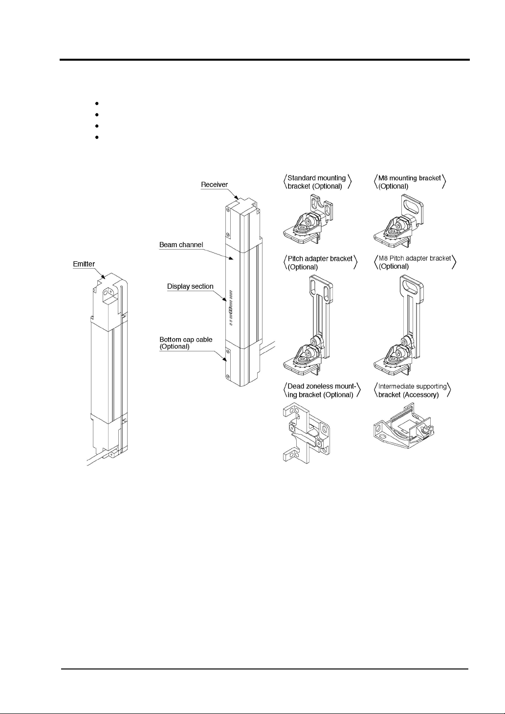
<Emitter>
It emits light to the receiver facing it. Furthermore, the status of the emitter and the receiver is
indicated on its display section.
<Receiver>
It receives light from the emitter facing it. Simultaneously, it turns ON the control output
(OSSD 1, OSSD 2) when the all beam channels receive light from emitter, and it turns OFF
the control output (OSSD 1, OSSD 2) when one or more beam channels are blocked light.
Besides, the receiver displays its status on the display section.
Note: In case of using the muting function, the following items, 12-core bottom cap cable (
SFB-CCB -MU
bottom cap cable, muting sensor, and muting lamp separately.
) (optional), muting sensor and muting lamp are required. Please purchase 12-core
SFB-CB05-MU
When this device is used as safety equipment for press machines in Japan, use
SFPB-CB05-MU
/
SFPB-CCB -MU
(optional) for 12-core bottom cap cable.
<Beam channel>
The light emitting elements of the emitter and the light receiving elements of the receiver are
placed at the following intervals, 10mm (
(
SF4B-A -01
).
SF4B-F -01
), 20mm (
SF4B-H -01
),and 40mm
<Standard mounting bracket (optional)>
This bracket is to be used for mounting the emitter / receiver. It enables to adjust the horizontal mounting angle using the standard mounting bracket.
<M8 mounting bracket (optional)>
This allows the light curtain to be mounted at the rear side with one M8 hexagon-socket-head
bolt. Horizontal angle can be adjusted.
,
<Pitch adapter bracket (optional)>
This is used as the mounting bracket when changing over a previous light curtain with a
protective height of 200 to 750mm to this device. It is installed using two M5 hexagon-socket-head bolts. Horizontal angle can be adjusted.
<M8 pitch adapter bracket (optional)>
This is used as the mounting bracket when changing over a previous light curtain with a
protective height of 200 to 750mm to this device. It is installed using two M8 hexagon-socket-head bolts. Horizontal angle can be adjusted.
<Dead zoneless mounting bracket (optional)>
This dead zoneless bracket is used for mounting both emitter and receiver. This bracket is
useful for mounting the sensor to the limited mounting space.
<Intermediate supporting bracket (optional)>
This bracket is to be used for mounting the sensor having 79 beam channels or more for
SF4B-F -01,
SF4B-A -01
40 beam channels or more for
.
SF4B-H -01
, 20 beam channels or more for
- 12 -
SUNX Limited MJE-SF4B01 No.0005-03V
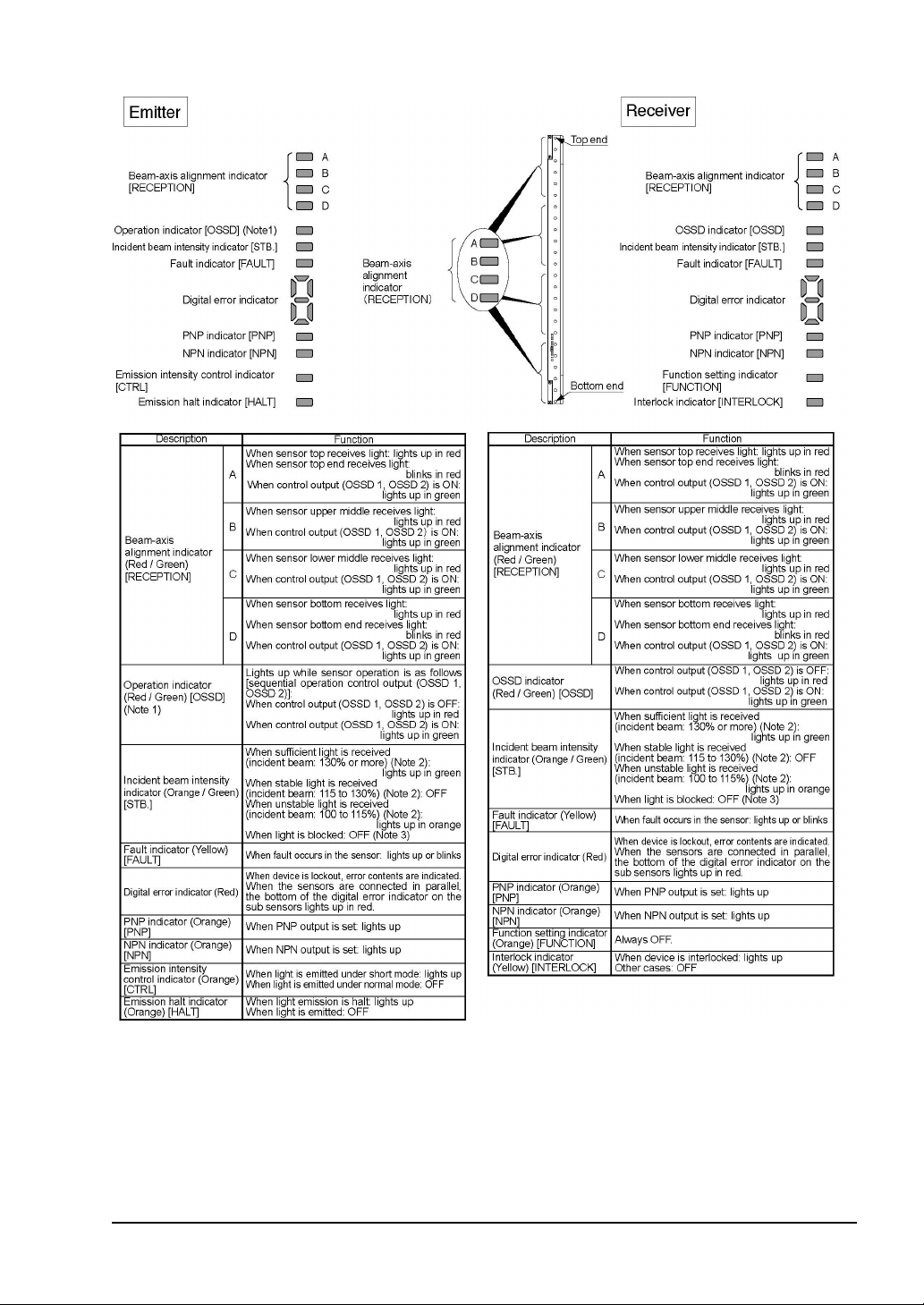
<Display section>
Notes: 1) Since the color of the operation indicator changes according to ON / OFF status of the control output (OSSD
2) The threshold where the control output (OSSD 1, OSSD 2) changes from OFF to ON is applied as ‘100%
3) The status ‘when light is blocked’ refers to the status that the some obstacle is existed in the sensing area.
4) The description given in [ ] is marked on the sensor.
1, OSSD 2), the operation indicator is marked as ‘OSSD’ on the sensor.
incident beam intensity’.
SUNX Limited MJE-SF4B01 No.0005-03V
- 13 -
2-3
y
Protection Area
2-3-1 Sensing Area
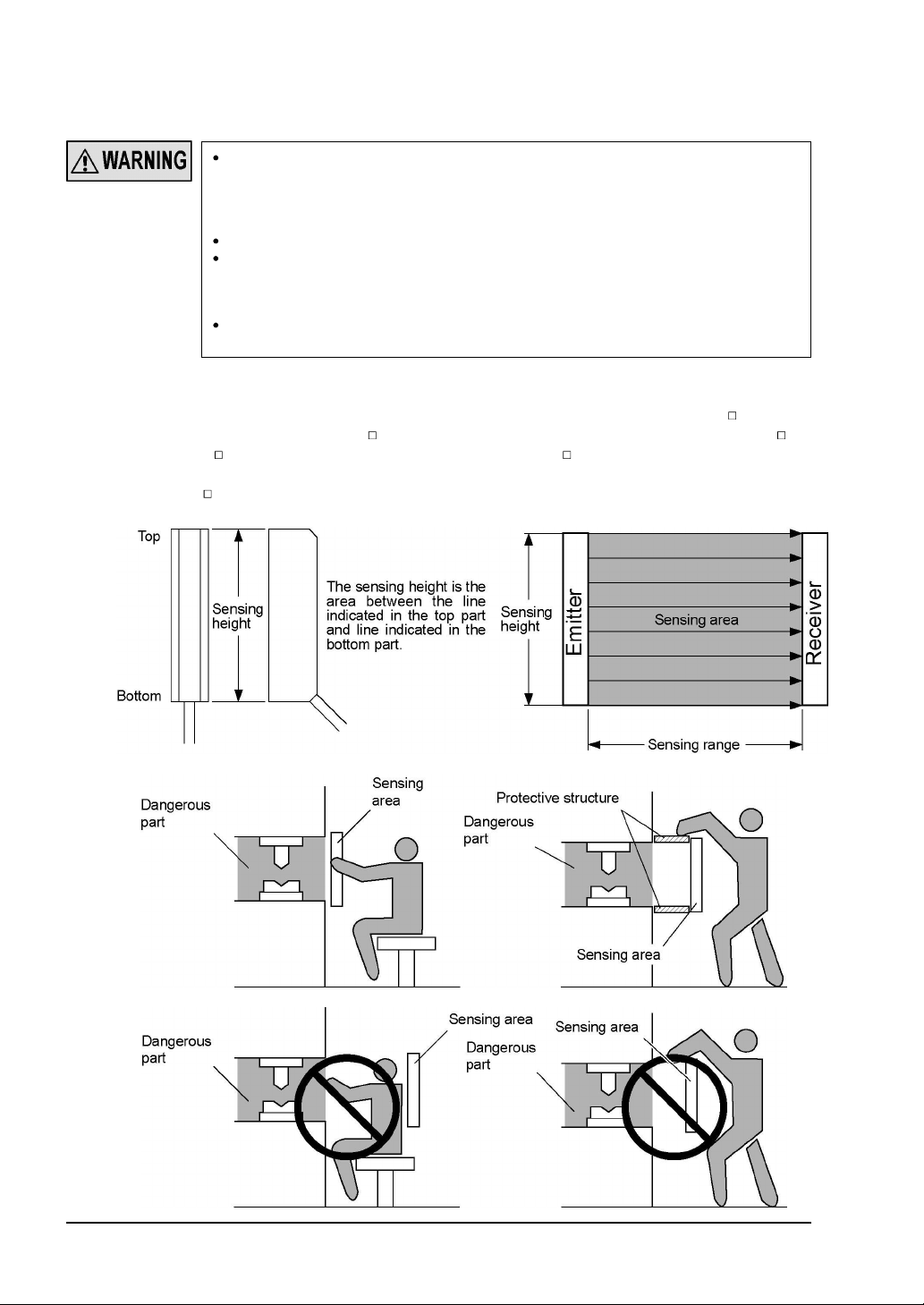
Be sure to install protection structure around the machine so that the operator must pass
through the sensing area of this device to reach the dangerous parts of the machine.
Furthermore, ensure that some part of the operator’s body always remains in the sensing
area when operation is done with the dangerous parts of the machine. Failure to do so can
result in serious injury or death.
Do not use any reflection type or recursive reflection type arrangement.
When connecting the sensor, use the correct combination of emitter and receiver (same
beam pitch and number of beam channels) and match their top-bottom orientation. Combining different types of emitter and receiver could produce a non-sensing area, which ma
result in serious injury or death.
Furthermore, facing several receivers towards one emitter, or vice versa, could produce a
non-sensing area or cause mutual interference, which may result in serious injury or death.
The sensing area is the zone formed by the sensing height of the sensor and the sensing
range between the emitter and the receiver. The sensing height is determined by the number
of beam channels. Furthermore, the sensing range can be 0.3 to 9m for
64 beam channels) and
and
SF4B-H -01
(72 to 96 beam channels) and
SF4B-A -01
(6 to 32 beam channels), 0.3 to 7m for
SF4B-A -01
(36 to 48 beam channels).
Take care that the sensing range becomes short after mounting either protection cover
FC-SFBH-
(
) (optional). Take care that if the sensing range is less than 0.3m, malfunction
may occur due to the optical structure.
SF4B-H -01
(12 to
SF4B-F -01
<Example of Correct Installation>
<Example of Incorrect Installation>
- 14 -
SUNX Limited MJE-SF4B01 No.0005-03V
2-3-2 Safety Distance
r
t
t
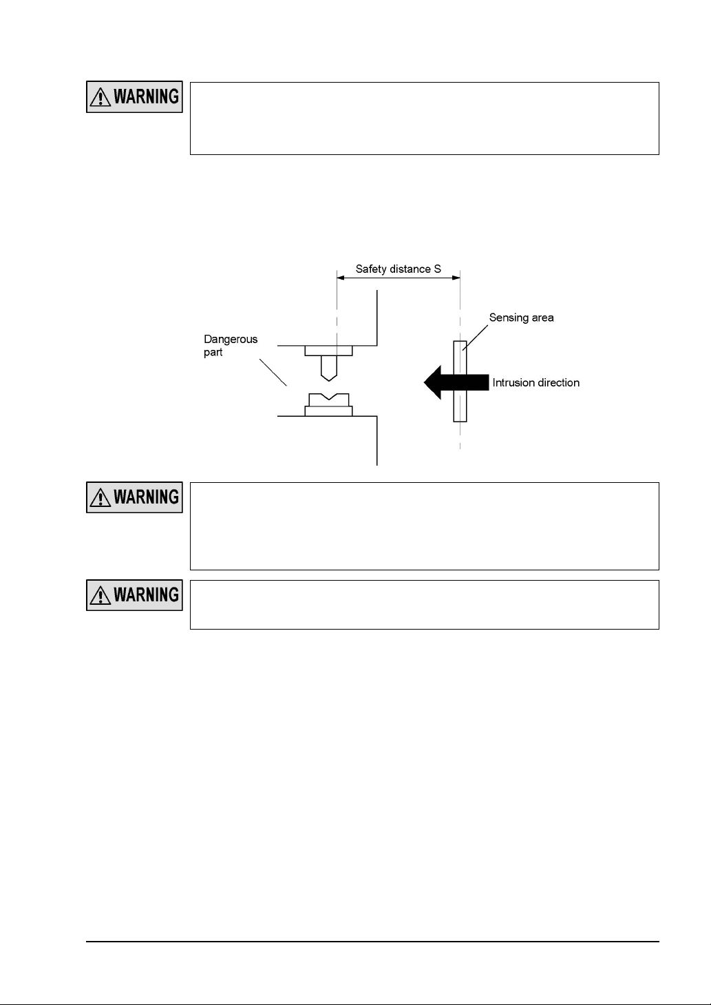
Calculate the safety distance correctly, and always maintain the distance which is equal to o
greater than the safety distance, between the sensing area of this device and the dangerous
parts of the machine. If the safety distance is miscalculated or if sufficient distance is no
maintained, the machine will not stop quickly before reaching to the dangerous parts, which
can result in serious injury or death.
The safety distance is the minimum distance that must be maintained between the light curtain and the dangerous parts of the machine so that the machine can be stopped before a
human body or an object can reach the dangerous parts.
The safety distance is calculated based on the equation described in the next page when a
person moves perpendicular (normal intrusion) to the sensing area of the area sensor.
Before designing the system, refer to the relevant standards of the region where this device is
to be used, and then install this device.
Furthermore, the equation described in the next pages is to be used only in case the intrusion
direction is perpendicular to the sensing area. In case the intrusion direction is not perpendicular to the sensing area, be sure to refer to the relevant standard (regional standard,
specification of the machine, etc.) for details of the calculation.
The max. response time of the machine is from the point that the machine receives the hal
signal from this device to the point that the dangerous part of the machine stops. The max.
response time of the machine should be timed with the machine to be actually used.
SUNX Limited MJE-SF4B01 No.0005-03V
- 15 -

[For use in Europe (EU) (as EN 999)] (Also applicable to ISO 13855)
(For intrusion direction perpendicular to the sensing area)
<In case that the minimum sensing object is ø40mm or less>
Equation 1 S = K x T + C
S : Safety distance (mm)
Minimum required distance between the sensing area surface and the dangerous
parts of the machine
K : Intrusion velocity of operator’s body or object (mm/s)
Taken as 2,000 (mm/s) for calculation
T : Response time of total equipment (s)
T = Tm+ T
SF4B01
Tm: Maximum halting time of device (s)
T
SF4B01
: Response time of this device (s)
C : Additional distance calculated from the size of the minimum sensing object of
the sensor (mm)
However, the value of C cannot be 0 or less.
C = 8 x (d - 14)
d: Minimum sensing object diameter (mm)
<Reference>
For calculating the safety distance S, there are the following five cases.
First calculate by substituting the value K = 2,000 (mm/s) in the equation above. Then, classify the obtained
value of S into three cases, 1) S < 100, 2) 100
For Case 3) S > 500, recalculate by substituting the value K = 1,600 (mm/s). After that, classify the calculation
result into two cases, 4) S
’.
Europe
For calculating T
When this device is used in the ‘PSDI Mode’, an appropriate safety distance S must be calculated.
For details, be sure to refer to the standards or regulations applicable in each region or country.
m
(maximum halt time of the device), use a special device called a ‘brake monitor’.
500 and 5) S > 500. For details, refer to ‘
S 500, and 3) S > 500.
Calculation Example 1 For use in
<In the case the minimum sensing object is ø40mm or less>
Equation S = K x T + C
S : Safety distance (mm)
K : Intrusion velocity of operator’s body or object (mm/s)
Taken as 1,600 (mm/s) for calculation
T : Response time of total equipment (s)
T = Tm+ T
SF4B01
T
m
: Maximum halting time of device (s)
T
SF4B01
: Response time of this device (s)
C : Additional distance calculated from the size of the minimum sensing object of
the sensor (mm)
C = 850 (mm)
- 16 -
SUNX Limited MJE-SF4B01 No.0005-03V

<Calculation Example>
Calculation Example 1 For use in Europe
(OFF response time: 14ms or less, minimum sensing object diameter: 14mm)
First, calculate with K = 2,000.
S = K x T + C
= K x (T
= 2,000 x (T
= 2,000 x T
= 2,000 x T
m
+ T
) + 8 x (d - 14)
SF4B01
+ 0.014) + 8 x (14 - 14)
m
+ 2,000 x 0.014
m
+ 28
m
If the result is:
1) In case S < 100 (mm)
Safety distance S is taken as 100 (mm)
2) In case 100
Safety distance S is taken as 2,000 x T
S 500 (mm)
+ 28 (mm)
m
3) In case S > 500 (mm)
S = K’ x (T
= 1,600 x (T
= 1,600 x T
= 1,600 x T
+ T
m
) + 8 x (d - 14)
SF4B01
+ 0.014) + 8 x (14 - 14)
m
+ 1,600 x 0.014
m
+ 22.4
m
then, calculate again.
If the result is:
4) In case S
500 (mm)
Safety distance S is taken as 500 (mm)
5) In case S > 500 (mm)
Safety distance S is taken as 1,600 x T
+ 22.4 (mm)
m
In case this device is installed in a system with a maximum halting time of 0.1 (s)
S = 2,000 x T
+ 28
m
= 2,000 x 0.1 + 28
= 228
Since this value matches with Case 2) above, S is 228 (mm).
In case this device is installed in a system with a maximum halting time of 0.4 (s)
S = 2,000 x T
+ 28
m
= 2,000 x 0.4 + 28
= 828
Since this value matches with Case 3) above,
S = 1,600 x T
+ 22.4
m
= 1,600 x 0.4 + 22.4
= 662.4
Since this value matches with Case 5) above, S is 662.4 (mm).
SUNX Limited MJE-SF4B01 No.0005-03V
- 17 -
[For use in the United States of America (as per ANSI B11.19)]
Equation 2 S = K x (Ts+ Tc+ T
SF4B01
+ Tbm) + Dpf
S : Safety distance (mm)
Minimum required distance between the sensing area surface and the dangerous
parts of the machine
K : Intrusion speed {Recommended value in OSHA is 63 (inch/s) [ 1,600 (mm/s)] }
ANSI B11.19 does not define the intrusion speed ‘K’. When determining K, consider possible factors including physical ability of operators.
T
: Halting time calculated from the operation time of the control element (air
s
valve, etc.) (s)
T
: Maximum response time of the control circuit required for functioning the
c
brake (s)
T
T
: Response time of this device (s)
SF4B01
: Additional halting time tolerance for the brake monitor (s)
bm
The following equation holds when the machine is equipped with a brake monitor.
bm
= Ta - (Ts+ Tc)
T
T
a
: Setting time of brake monitor (s)
When the machine is not equipped with a brake monitor, it is recommended that
20% or more of (T
pf
D
: Additional distance calculated from the size of the minimum sensing of the
s
+ Tc) is taken as additional halting time.
sensor (mm)
SF4B-F -01
SF4B-H -01
SF4B-A -01
Dpf = 23.8mm
Dpf = 61.2mm
Dpf = 129.2mm
Dpf = 3.4 x (d - 0.276) (inch)
3.4 x (d - 7) (mm)
d: Minimum sensing object diameter 0.552 (inch) 14 (mm)
Minimum sensing object diameter 0.985 (inch)
Minimum sensing object diameter 1.772 (inch)
25 (mm)
45 (mm)
SF4B-F -01
SF4B-H -01
SF4B-A -01
Note that the value of Dpf cannot be 0 or less.
<Reference>
Since the calculation above is performed by taking 1 (inch) = 25.4 (mm), there is a slight difference between the
representation in (mm) and that in (inch). Refer to the relevant standard for the details.
<Calculation Example>
Calculation Example 2 For use in the United States of America
[OFF response time: 14ms or less, minimum sensing object diameter: 0.552 inch 14 (mm)]
S = K x (Ts+ Tc+ T
= 63 x (T
= 63 x (T
= 63 x T
= 63 x T
+ 0.014) + 3.4 x (d - 0.276) (inch)
a
+ 0.014) + 3.4 x (0.552 - 0.276)
a
+ 63 x 0.014 + 3.4 x 0.276
a
+ 1.8204
a
SF4B01
+ Tbm) + Dpf
63 x Ta+ 1.82 (inch)
In case this device is installed in a system with a maximum halting time 0.1 (s)
S = 63 x T
+ 1.82
a
= 63 x 0.1 + 1.82
= 8.12 (inch)
206.248 (mm)
Hence, as per the calculations S is 206.2 (mm).
<Reference>
Since the calculation above is performed by taking 1 (inch) = 25.4 (mm), there is a slight difference between the
representation in (mm) and that in (inch). Refer to the relevant standard for the details.
- 18 -
SUNX Limited MJE-SF4B01 No.0005-03V

[When this device is used as a safety equipment for press machines in Japan]
[Standards for power press machine structure]
<Safety distance (reference)>
The following formula is for the safety distance given in the ‘Standards for power press machine structure’ (Ministry of Health, Labor and Welfare Notice No.116, issued December 26,
1977) based on the Industrial Safety and Health Law Provision 44. The following example
should be considered a reference value.
When actually installing the light type press machine safety equipment at the press machine,
follow the ‘Standards for power press machine structure’.
Formula (from Standards for power press machine structure, Provision 50)
D = 1.6 x (T
In the above formula, D, T
+ TS)
L
and TS respectively indicate the following values.
L
D : Distance between light type press machine safety equipment's beam-axis and danger limit
(danger source) (mm)
T
: Time from shielding of light to operation of press machine's sudden halting mechanism
L
[The device delay time (14ms)]
T
: Time from start of press machine's sudden stop mechanism to stop of slide (ms)
S
The safety distance (D) is calculated from the formula to determine the installation distance (A).
If the distance between the beam-axis and bolster front line exceeds a horizontal distance of
400mm, or if the distance is shorter than 400mm but the operator could enter between the
beam channels and bolster front line, install the auxiliary beam channels or an additional
guard.
<Calculation Example>
Setting the press machine's maximum stop time to 200ms.
D = 1.6 x (200 + 14)
= 342.4 (mm)
The safety distance in this case is D = 342.4 (mm).
<Installing the auxiliary beam channels>
Connecting the devices used for the main beam channels and auxiliary beam channels serially
is recommended. A series connection can prevent mutual interference.
(1) If installing the auxiliary beam channels when there is space between the main beam
channels radiated on the light type press machine safety equipment, installed with the
safety distance, and the bolster front line in which the operator could enter, install so that
the horizontal distance between the main beam channels and auxiliary beam channels is
200mm or less, and so that the horizontal distance between the bolster and the auxiliary
beam channels closest to the bolster is 200mm or less.
(2) Install the auxiliary beam channels so that it is horizontal to the bolster's front line, and so that
it is at a point approximately the same as the operator's waist.
SUNX Limited MJE-SF4B01 No.0005-03V
- 19 -

[When this device is used as a safety equipment for press machines in Japan]
The emitter and receiver set installed to directly protect the total length of the press machine's
stroke length and slide adjustment range is called the ‘main beam channels’. Other emitters
and receivers installed for other purposes are called the ‘auxiliary beam channels’. When installing this device as the main beam channels, the beam channels with a protective height
larger than the total length of the press machine's stroke length and slide adjustment range
must be selected. If the distance between the center of the main beam channels and the bolster front line is 400mm or more, the auxiliary beam channels must be installed at 200mm intervals between the main beam channels and bolster to prevent operators from entering the
area.
Refer to ‘Policy on Press Machine Safety Equipment Control’ (Ministry of Health, Labor and
Welfare, Basic Publication No.446-2, issued on July 9, 1993) for details.
When using the auxiliary beam channels, set the auxiliary beam channels so that the
machine operator cannot stand between the machine and this device, and so that the
operator cannot go past this device's protective range and enter the machine's dangerous areas. Failure to use an auxiliary beam channels could result in death or serious
injury.
- 20 -
SUNX Limited MJE-SF4B01 No.0005-03V
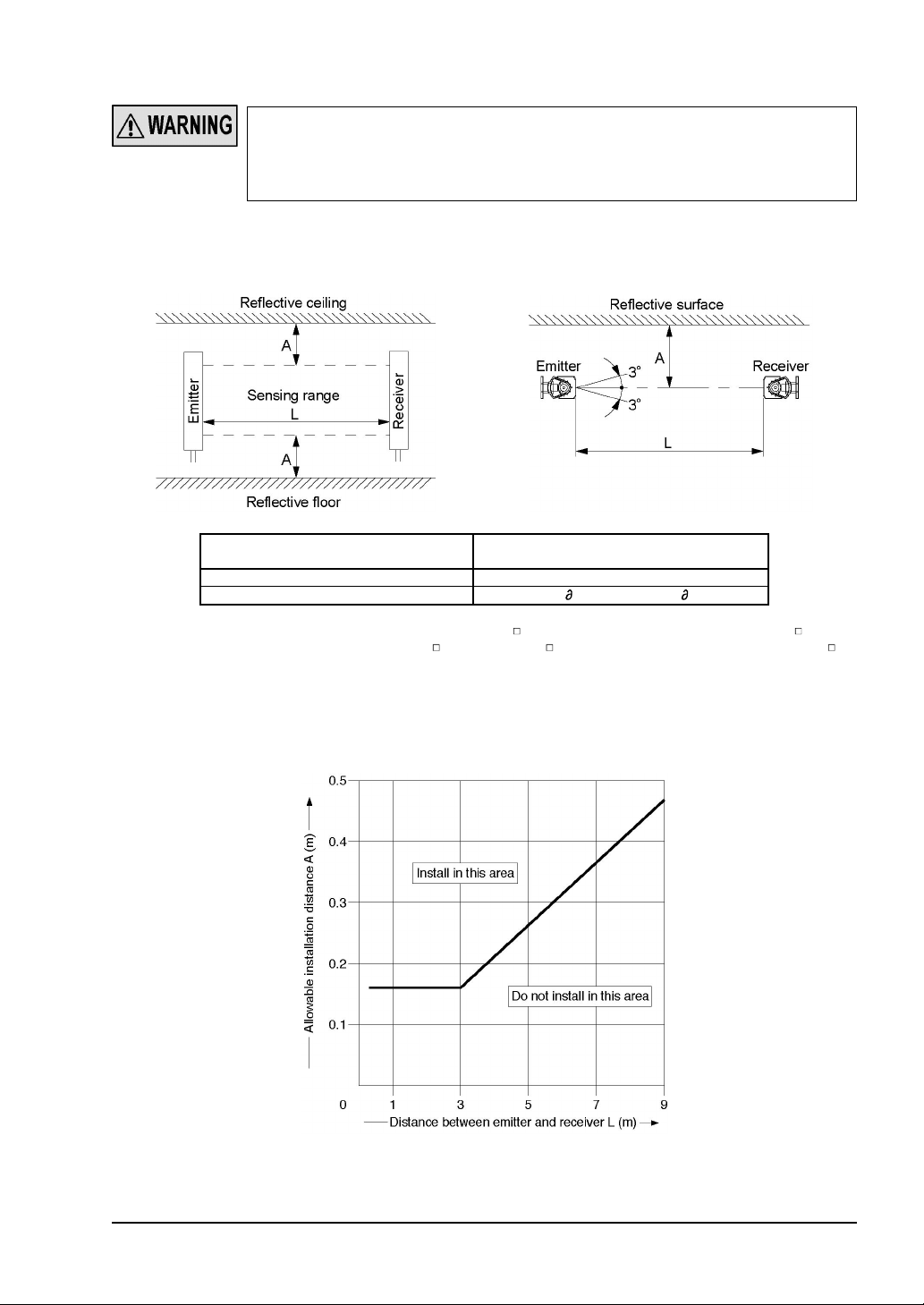
2-3-3 Influence of Reflective Surfaces
If there exists a reflective surface in the place where this device is to be installed, make sure
to install this device so that reflected light from the reflective surface does not enter into the
receiver, or take countermeasures such as painting, masking, roughening, or changing the
material of the reflective surface, etc. Failure to do so may cause the sensor not to detect,
resulting in death or serious injury.
Install this device at a distance of at least A (m) (given below) away from reflective surfaces
such as metal walls, floors, ceilings, workpieces, covers, panels or glass surfaces.
<Side View> <Top View>
Distance between emitter and receiver
(Sensing range L)
0.3 to 3m 0.16m
3 to 9m (Note 1) L x tan = L x 0.052 (m) ( = 3°)
Notes: 1) The sensing range L is applicable to
32 beam channels). For
(36 to 48 beam channels), the distance between emitter and receiver is 3 to 7m.
2) The effective aperture angle for this device is ±2.5° (when L > 3m) as required by IEC 61496-2 / UL
61496-2. However, install this device away from reflective surfaces considering an effective aperture
angle of ±3° to take care of beam misalignment, etc. during installation.
SF4B-F -01
SF4B-H -01
and
Allowable installation distance A
(12 to 64 beam channels) and
SF4B-H -01
(72 to 96 beam channels) and
SF4B-A -01
SF4B-A -01
(6 to
Allowable Distance from Sensor Beam Channel to Reflective Surface
SUNX Limited MJE-SF4B01 No.0005-03V
- 21 -
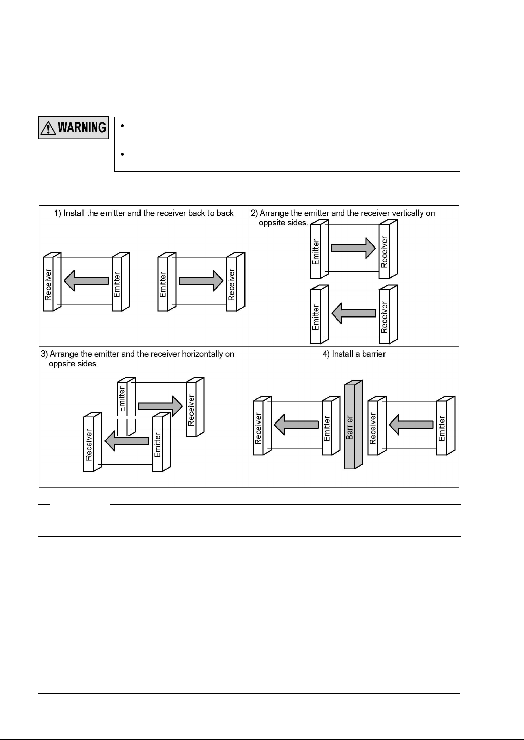
2-3-4 Sensor Placement
y
This is the configuration when two or more sets of emitter and receiver facing each other are
placed without series or parallel connection between them. It is used for the case that there is
a problem in wiring or for system evaluation in case of addition of equipment. Perform an
operation test by referring to ‘
Refer to the examples of sensor placement given below and understand them thoroughl
before installing the sensors. Improper sensor placement could cause sensor malfunction,
which can result in serious injury or death.
If this device is used in multiple sets, arrange them to avoid mutual interference. If mutual
interference occurs, it can result in serious injury or death.
<Example of sensor placement>
2-6-2 Operation Test
’.
<Reference>
The above figures are just examples of sensor placement. If there are any questions or problems, please contact
our office.
SUNX Limited MJE-SF4B01 No.0005-03V
- 22 -
2-4
r
o
f
r
Mounting
2-4-1 Mounting of the Mounting Bracket
For selecting the appropriate mounting bracket matched to the installation environment,
the mounting bracket is not incorporated in this device. Please purchase the optional
mounting bracket to fit on the mounting environment.
Do not apply the load such as forced bending to the cable of this device. Applying imprope
load could cause the wire breakage.
The minimum bending radius of the cable
the cable bending radius.
When this device is used as safety equipment for press machines in Japan, be sure t
use the cable with protective tube (
the
SFPB
considering the cable bending radius.
- is R55mm (When the cable protective tube is fitted). Mount the senso
<Reference>
Mount the emitter and the receiver at the same level and parallel to each other. The effective aperture angle of
this device is ±2.5° or less for a sensing distance exceeding 3m.
Unless otherwise specified, the following mounting procedure is common for both emitter and receiver. For the
preparation of the mounting, prepare the mounting holes on the mounting surface by referring to ‘
Dimensions
’.
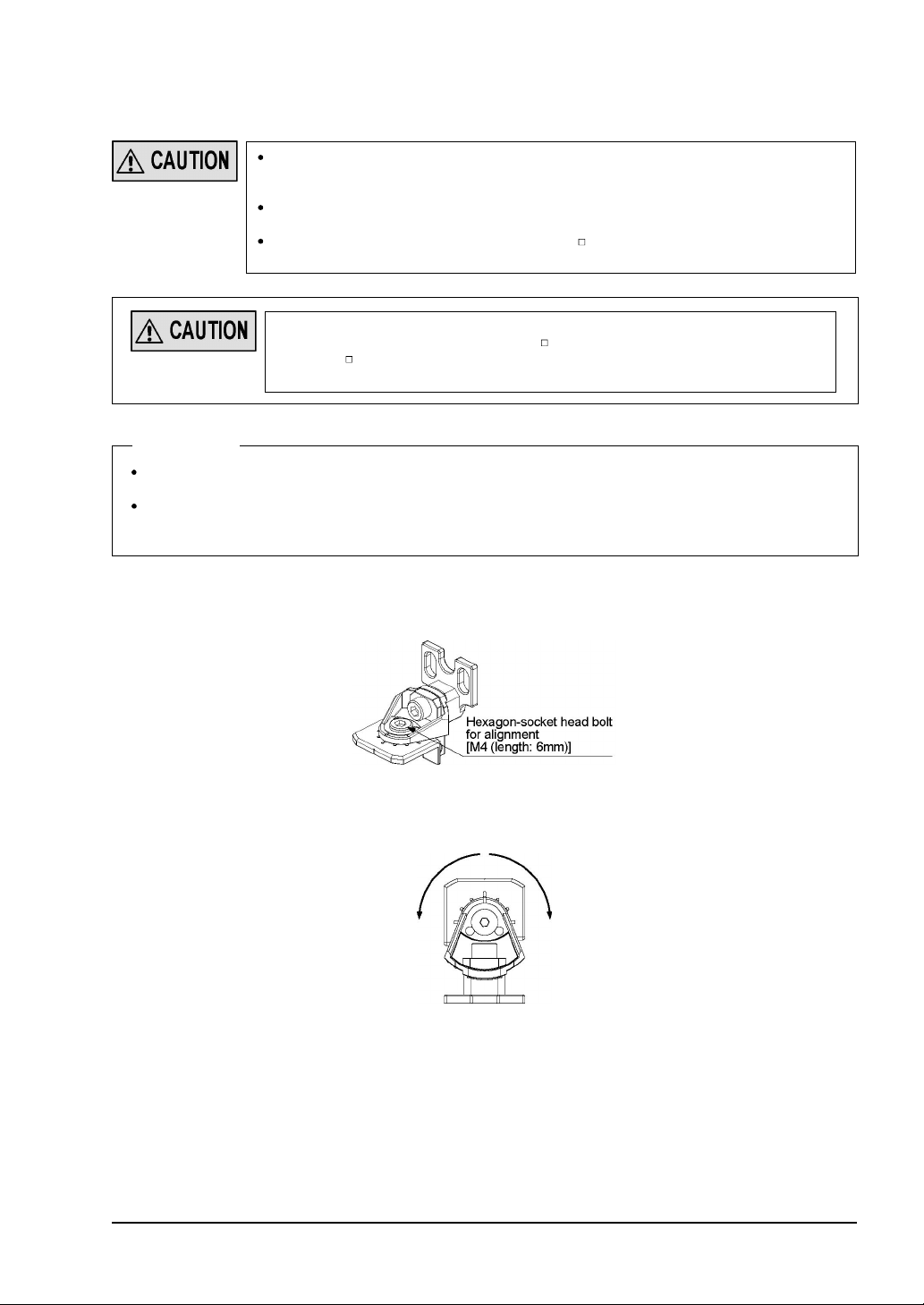
<In case of using standard mounting bracket (MS-SFB-1) (optional)>
1. Loosen the hexagon-socket head bolt for alignment [M4 (length: 6mm)] of the standard
mounting bracket.
SFB
- is R6mm. Mount the sensor considering
SFPB
- ) (optional). The minimum bending radius o
6-3
2. As shown in the figure below, adjust the direction of this device and that of installation
surface by declining the bracket, and tighten and fix the hexagon-socket head bolt for
alignment. The tightening torque should be 2N
㨯
m or less.
SUNX Limited MJE-SF4B01 No.0005-03V
- 23 -
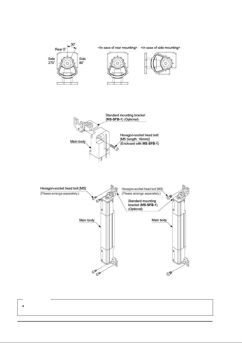
The marks are engraved on the standard mounting bracket so as to adjust the direction of
.
this sensor by 30 degrees
Set and fix both emitter and receiver using the marks so that
they face to each other.
Refer to ‘
2-6-1 Beam-axis Alignment
’ for details of the beam-axis alignment.
3. Set the device with its mounting hole on the side just overlapping with the mounting hole
of the standard mounting bracket, and fix the standard mounting bracket with the accessory hexagon-socket head bolt [M5 (length: 16mm)].
The tightening torque should be 1.2N
㨯
m or less.
4. Set the standard mounting bracket (
MS-SFB-1
surface using either four hexagon-socket head bolts [M5 (please arrange separately)] or
two hexagon-socket head bolts [M8 (please arrange separately)].
Note: For the models that the intermediate supporting bracket (
intermediate supporting bracket (
supporting bracket (MS-SFB-2) (accessory)>
MS-SFB-2
<Reference>
Mounting method of the M8 mounting bracket (
M8 pitch adapter bracket (
MS-SFB-4-T
) is the same as the standard mounting bracket (
MS-SFB-1-T
) that is ready for setting to the mounting
MS-SFB-2
). For details, refer to
.
), the pitch adapter bracket (
) is enclosed with, be sure to use the
<In case of using intermediate
MS-SFB-4
MS-SFB-1
) and the
).
- 24 -
SUNX Limited MJE-SF4B01 No.0005-03V
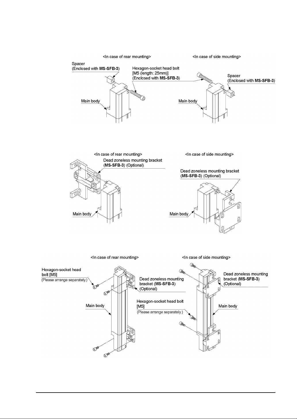
< In case of using dead zoneless mounting bracket (MS-SFB-3) (optional)>
1. Set the spacer attached to the dead zoneless mounting bracket (
MS-SFB-3
) onto the
mounting hole on the side of the top (bottom) end part of this device, and insert the hexagon-socket head bolt [M4 (length: 25mm)] into the hole.
2. Adjust the hexagon-socket head bolt with the status described in Step 1 to the mounting
hole of the dead zoneless mounting bracket, and tighten and fix the bracket.
The tightening torque should be 1.2N
㨯
m or less.
3. Set the dead zoneless mounting bracket that is ready for setting to the mounting surface
using four hexagon-socket head bolts [M5 (please arrange separately)].
Note: For the models that the intermediate supporting bracket (
intermediate supporting bracket (
supporting bracket (MS-SFB-2) (accessory)>
MS-SFB-2
). For details, refer to
.
MS-SFB-2
) is enclosed with, be sure to use the
<In case of using intermediate
SUNX Limited MJE-SF4B01 No.0005-03V
- 25 -
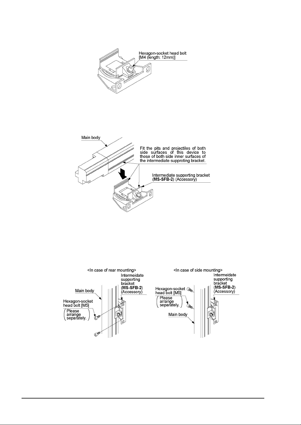
<In case of using intermediate supporting bracket (MS-SFB-2) (accessory)>
1. Loosen the hexagon-socket head bolt [M4 (length: 12mm)] screw of the intermediate
supporting bracket (
MS-SFB-2
).
2. Insert the side of this device into the intermediate supporting bracket, and fix it with the
hexagon-socket head bolt [M4 (length: 12mm)].
The tightening torque should be 1.2N
Refer to ‘
6-3 Dimensions
’ for the mounting position of the intermediate supporting
㨯
m or less.
bracket.
When setting the intermediate supporting bracket on both side surfaces of this device, fit
the four pits and projectiles of both side surfaces of the main body to those of both side
surfaces (inner surfaces) of the intermediate supporting bracket.
3. After aligning the beam axis, mount the intermediate supporting bracket to the mounting
surface using two hexagons-socket head bolts [M5 (please arrange separately)].
For the details of beam axis alignment, refer to ‘
2-6-1 Beam-axis Alignment’
.
- 26 -
SUNX Limited MJE-SF4B01 No.0005-03V

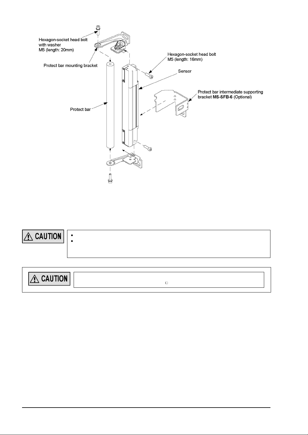
<Mounting protect bar (MC-SFBH- ) (optional)>
1. Loosen the hexagon-socket head bolt for alignment [M4 (length: 6mm)] of the protect bar
mounting bracket.
2. Align this device with the mounting surface inclining the bracket as shown in the
figure below, and then tighten the hexagon-socket head bolt for alignment.
The tightening torque should be 2N㨯m or less.
Marks are engraved on the protect bar mounting bracket, which enables the angle of the
emitter / receiver to be adjusted by 30 degrees. Before fixing, adjust the protect bar
mounting bracket using the engraved marks so that the emitter and receiver face each
other.
For details of alignment, refer to ‘
2-6-1 Beam-axis Alignment
’.
3. Mount the protect bar mounting bracket with the accessory two hexagon-socket head
bolts [M5 (length: 16mm)]. The tightening torque should be 1.2N
4. Mount the protect bar to the protect bar mounting bracket with a hexagon-socket head bolt
[M5 (length: 20mm)]. The tightening torque should be 2.5N
5. If the intermediate supporting bracket is used, mount the bracket with two hexagon-socket
bolts [M5 (please arrange separately)] on the mounting surface temporarily. Furthermore,
if the protect bar intermediate supporting bracket (
bracket with a hexagon-socket bolt [M8 (please arrange separately) on the mounting
surface temporarily.
6. Mount the protect bar mounting bracket with a hexagon-socket bolt [M8 (please arrange
separately)] on the mounting surface temporarily.
7. Adjust the angle of the emitter and the receiver horizontally within the adjustable range of
the elongate hole, and tighten the hexagon-socket bolt [M8 (please arrange separately)].
8. Adjust the intermediate supporting bracket and protect bar intermediate supporting
bracket, and then tighten the hexagon-socket bolt [M8 (please arrange separately)].
SUNX Limited MJE-SF4B01 No.0005-03V
MS-SFB-6
㨯
m or less.
㨯
m or less.
) is used, also mount the
- 27 -
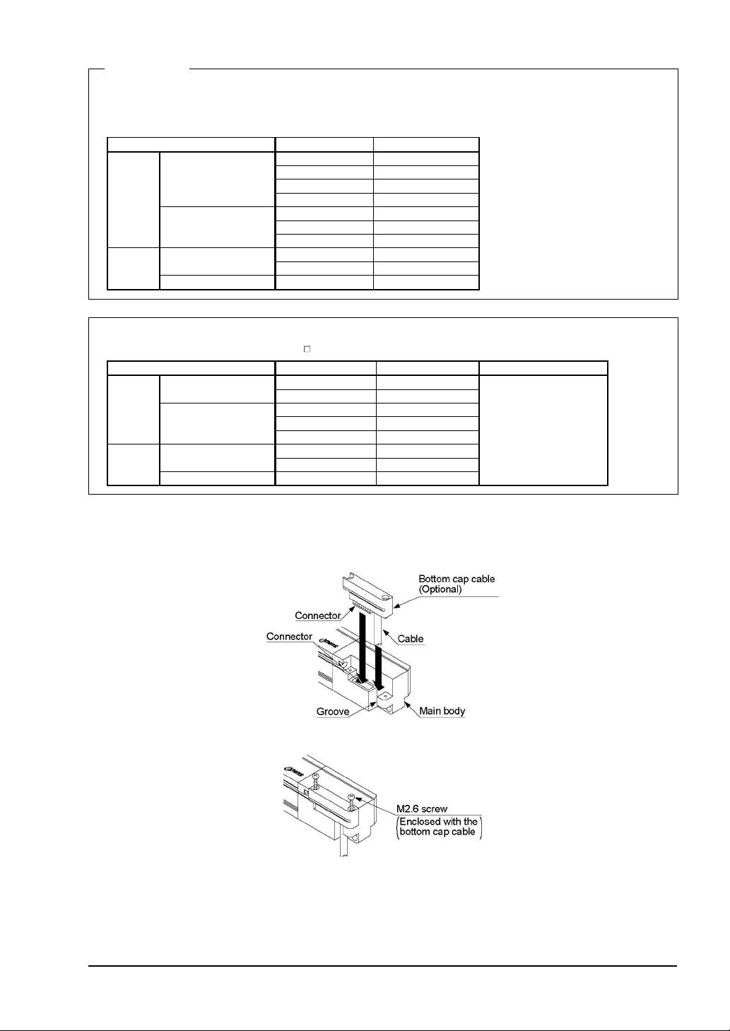
2-4-2 Mounting of the Bottom Cap Cable (optional)
r
The cable is not enclosed with this device.
Mount the bottom cap cable (optional) in accordance with the following procedure.
Do not lose any screws during extension / dismantling.
The bottom cap cables are distinguished with the color of the connectors, the color of the
connector for emitter is gray and that of the receiver is black. Connect the cable to emitte
and receiver without fail using their colors as the guide.
- 28 -
When this device is used as safety equipment for press machines in Japan, be sure to
use the cable with protective tube (
SFPB
- ) (optional).
SUNX Limited MJE-SF4B01 No.0005-03V
<Reference>
There are two types of the bottom cap cable, 8-core type and 12-core type, and in addition to these types, two
more types are available for the bottom cap cable, discrete wire type and connector type. Select the bottom cap
cable as usage.
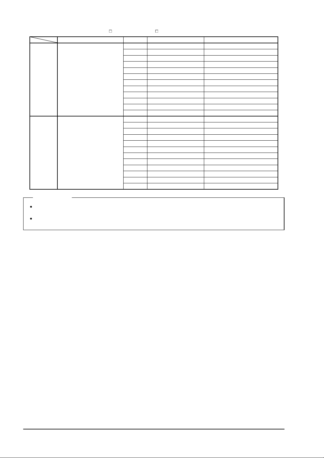
The length of the bottom cap cable differs depending on the model No.
Type Model No. Cable length (m)
8-core
12-core
Discrete wire type
Connector type
Discrete wire type
Connector type
SFB-CCB3
SFB-CCB7
SFB-CCB10
SFB-CCB15
SFB-CB05
SFB-CB5
SFB-CB10
SFB-CCB3-MU
SFB-CCB7-MU
SFB-CB05-MU
3
7
10
15
0.5
5
10
3
7
0.5
When this device is used as safety equipment for press machines in Japan, be sure to use the
cable with protective tube (
Type Model No. Cable length (m) Remarks
Discrete wire type
8-core
12-core
Connector type
Discrete wire type
Connector type
SFPB-
).
SFPB-CCB3
SFPB-CCB7
SFPB-CB05
SFPB-CB5
SFPB-CB10
SFPB-CCB3-MU
SFPB-CCB7-MU
SFPB-CB05-MU
3
7
0.5
5
10
3
7
0.5
The cable
tube is enclosed.
protective
<Mounting method>
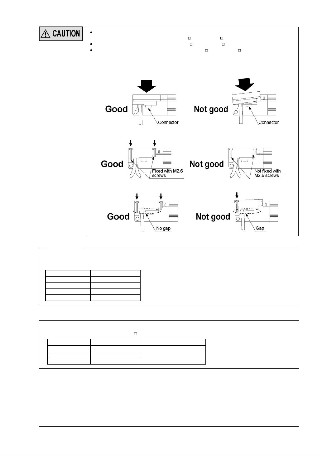
1. Insert the connector of the bottom cap cable (optional) into the connector of this device.
When inserting the connector, fit the cable to the groove of this device.
2. Tighten the two M2.6 screws. The tightening torque should be 0.3N·m or less.
SUNX Limited MJE-SF4B01 No.0005-03V
- 29 -
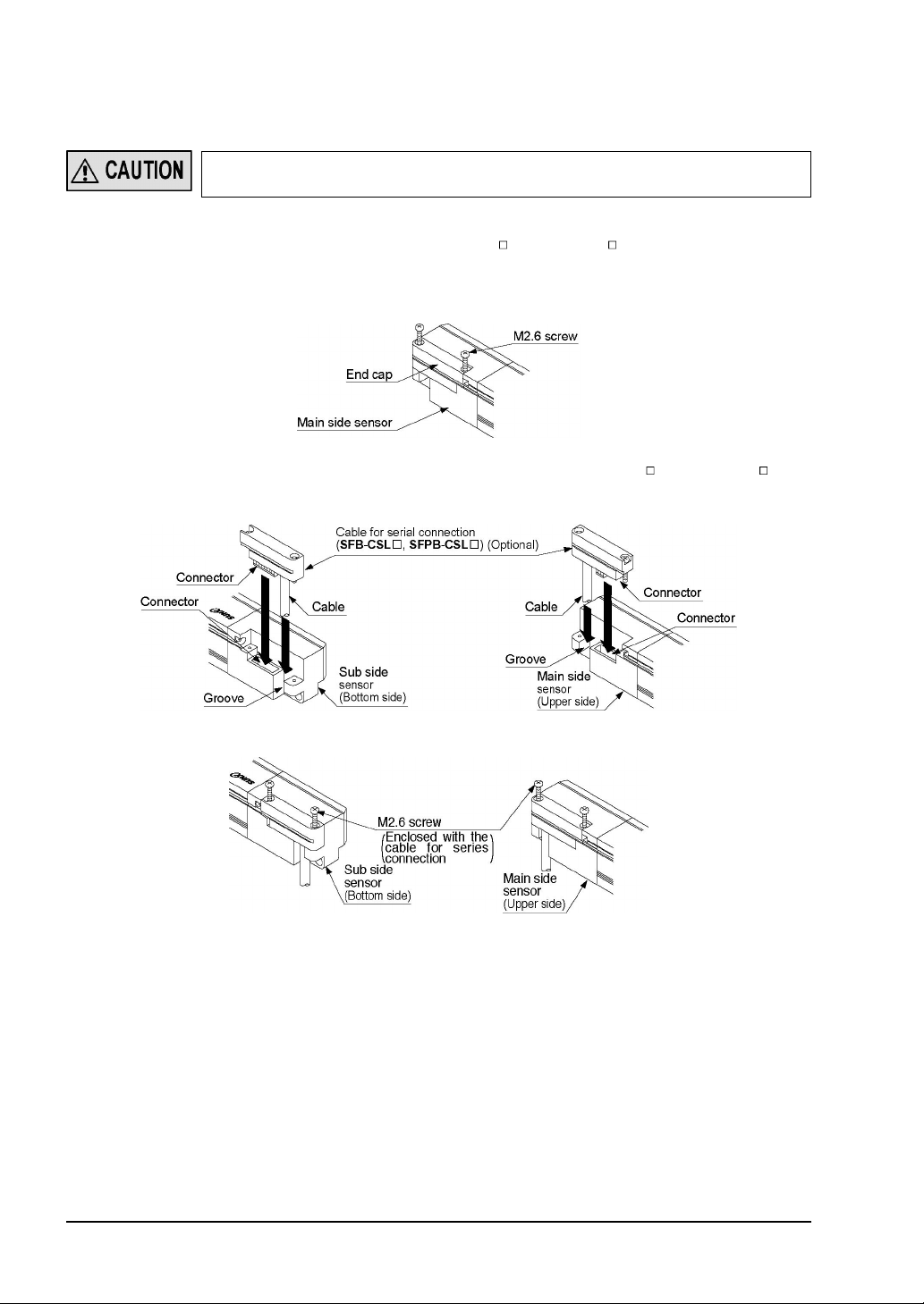
2-4-3 Extension and Dismantling of Sensor (Series Connection)
This section describes the extension method of the series connection using the options.
For constructing the series connection, the following procedure is required.
Do not lose any screws during extension / dismantling work.
Furthermore, do not mix emitters and receivers to mount in series connection.
<Mounting method of cable for series connection>
Replace the cable for series connection (
1. Loosen the two M2.6 screws of the end cap on the main side sensor (emitter and receiver
to which the synchronization line has been connected), and then remove the end cap from
the sensor.
SFB-CSL
/
SFPB-CSL
).
2. Insert the connector of the cable for series connection (
SFB-CSL
/
SFPB-CSL
tional) into the connector. When inserting the connector, fit the cable into the groove of this
device.
3. Tighten each two M2.6 screws. The tightening torque should be 0.3N·m or less.
) (op-
- 30 -
SUNX Limited MJE-SF4B01 No.0005-03V
y
Take care that the shape of the connectors for the bottom side and for the end cap side on
the cable for series connection (
The cable for series connection (
When the cable for series connection (
side sensor, take care of the following. If inserted without care, the connector pins ma
bend.
1) Do not insert the connector part aslant.
2) Do not pull the cables before tightening the M2.6 screws.
3) Do not insert the connector incorrectly and tighten the M2.6 screws.
SFB-CSL
SFB-CSL
/
SFPB-CSL
/
SFPB-CSL
SFB-CSL
) is different.
) cannot be extended.
/
SFPB-CSL
) is inserted to the main
<Reference>
There is no difference in the cable for series connection for the emitter and the receiver.
The length of the cable for series connection differs depending on the model No.
Model No. Cable Length (mm)
SFB-CSL01
SFB-CSL05
SFB-CSL1
SFB-CSL5
100
500
1,000
5,000
When this device is used as safety equipment for press machines in Japan, be sure to use the
cable with protective tube (
Model No. Cable Length (mm) Remarks
SFPB-CSL05
SFPB-CSL1
SFPB-CSL5
SFPB-
500
1,000
5,000
).
The cable protective tube
is enclosed.
<Dismantling the cable for series connection>
1. For dismantling the cable for series connection, follow the above procedure of
method of cable for series connection>
in reverse.
<Mounting
SUNX Limited MJE-SF4B01 No.0005-03V
- 31 -

[When this device is used as a safety equipment for press machines in Japan]
2-4-4 Mounting of the Cable Protective Tube
When this device is used as safety equipment for press machines in Japan, be sure to use
the optional cable with protective tube (
SFPB-
closed with the cable.
1. Cut the cable protective tube to match the length of the cable being used.
), and mount the cable protective tube en-
Note: The cable protection tube should be cut in the length that covers the whole cable (except the connector
part). However, when the bottom cap cable (
SFPB-CSL
tion (
overlaps this device (33mm approx.).
) is used, the cable protection tube is not necessary for the part of the cable which
SFPB-CCB
/
SFPB-CB
) or the cable for series connec-
2. Separate the protective tube as shown below.
3. Fit the cable into the tube.
4. Cover with another part of the protective tube.
- 32 -
SUNX Limited MJE-SF4B01 No.0005-03V

2-5
t
Wiring
Earth the machine or the support where the sensor is mounted on to frame ground (F.G.).
Failure to do so could cause the malfunction of the product by noise, resulting in serious
injury or death.
Furthermore, the wiring should be done in a metal box connected to the frame ground (F.G.).
Take countermeasure against the system to be applied for this device so as not to carry ou
the dangerous performance caused by the earth failure. Failure to do so could cause invalid for the system stop, resulting in serious body injury or death.
Make sure to insulate the ends of the unused lead wires.
<Reference>
Use a safety relay unit or an equivalent control circuit in safety for FSD.
2-5-1 Power Supply Unit
Wire correctly using a power supply unit which conforms to the laws and standards of the
region where this device is to be used. If the power supply unit is non-conforming or the wiring
is improper, it can cause damage or malfunction of this device.
<Reference>
A specialist who has the required electrical knowledge should perform the wiring.
The DC power supply unit must satisfy the conditions given below.
1) Power supply unit authorized in the region where this device is to be used.
2) Power supply unit conforming to EMC Directive and Low-voltage Directive (only for requiring CE marking
conformation).
3) Power supply unit conforming to the Low-voltage directive and with an output of 100VA or less.
4) The frame ground (F.G.) terminal must be connected to ground when using a commercially available
switching regulator.
5) Power supply unit with an output holding time of 20ms or more.
6) In case a surge is generated, take countermeasures such as connecting a surge absorber to the origin of
the surge.
7) Power supply unit corresponding to CLASS 2 (only for requiring UL / cUL conformation)
«Additional information» As provided in IEC 60536 (CLASS: Protection against Electric Shock), this
power supply should require no ground earth and satisfy the insulation distance called double insulation or reinforced insulation.
In case the power supply conforms to Low-voltage directive and has an output
of 100VA or less, it can be used as a suitable product.
SUNX Limited MJE-SF4B01 No.0005-03V
- 33 -
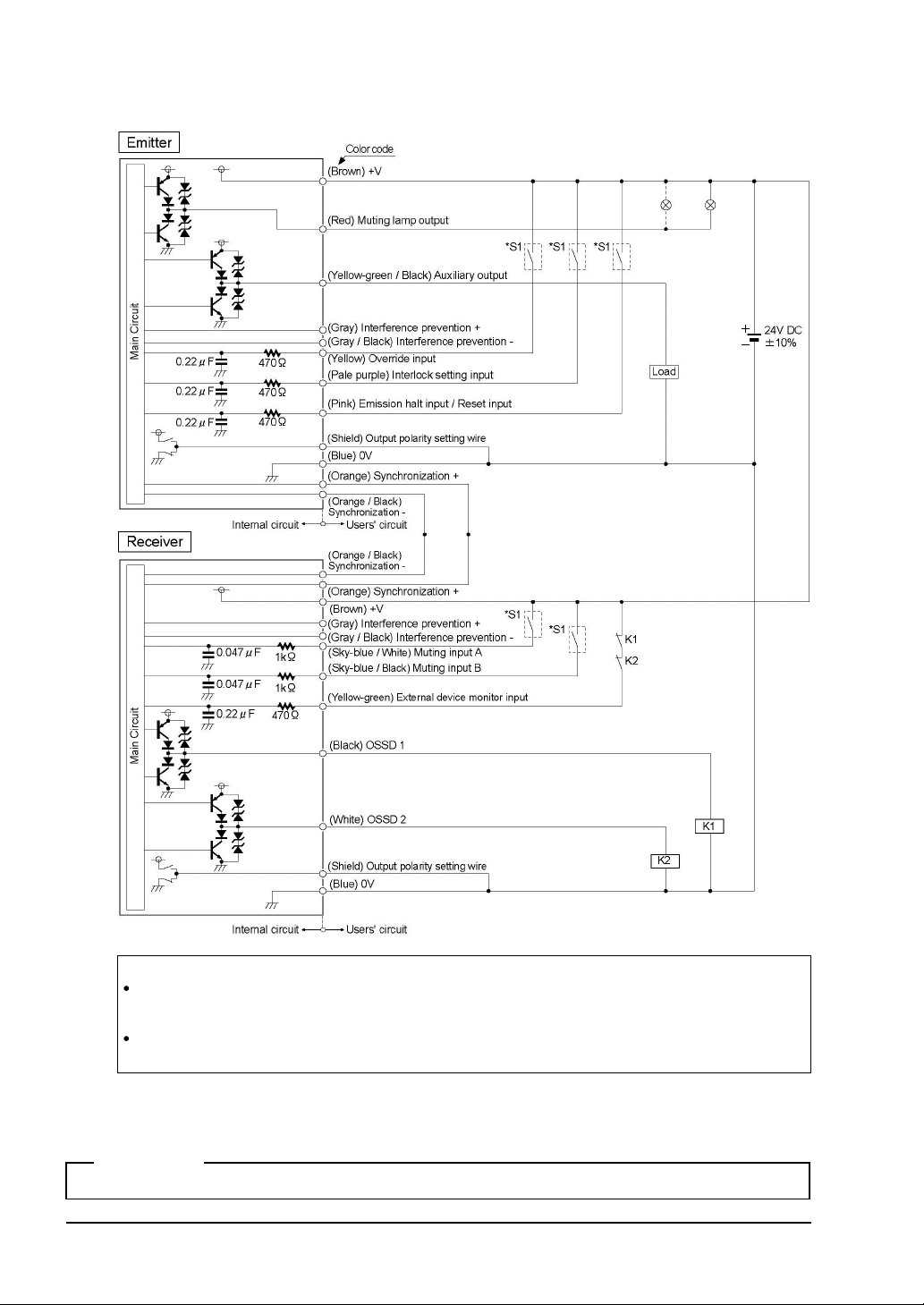
2-5-2 I/O Circuit Diagrams and Output Waveform
<In case of using I/O circuit for PNP output>
*S1
Switch S1
Emission halt input / Reset input
For manual reset: Vs to Vs - 2.5V (sink current: 5mA or less) : Emission halt (Note 1), Open: Emission
For auto-reset: Vs to Vs - 2.5V (sink current: 5mA or less) : Emission (Note 1), Open: Emission halt
Interlock setting input, Override input, Muting input A / B, External device monitor input
Vs to Vs - 2.5V (sink current: 5mA or less): Valid (Note 1), Open: Invalid
Notes: 1) Vs is the applying supply voltage.
2) The circuit diagram shown above is for 12-core cable to be used. For 8-core cable, red, yellow, grey,
grey / black, sky-blue / white, sky-blue / black, there is no lead wire.
<Reference>
K1, K2: External device (Forced guided relay or magnetic contactor)
SUNX Limited MJE-SF4B01 No.0005-03V
- 34 -

<In case of using I/O circuit for NPN output>
*S1
Switch S1
Emission halt input / Reset input
For manual reset: 0 to + 1.5V (source current: 5mA or less): Emission halt, Open: Emission
For auto-reset: 0 to + 1.5V (source current: 5mA or less): Emission, Open: Emission halt
Interlock setting input, Override input, Muting input A / B, External device monitor input
0 to + 1.5V (source current: 5mA or less): Valid, Open: Invalid
Note: The circuit diagram shown above is for 12-core cable to be used. For 8-core cable, red, yellow, grey, grey
/ black, sky-blue / white, sky-blue / black, there is no lead wire.
<Reference>
K1, K2: External device (Forced guided relay or magnetic contactor)
SUNX Limited MJE-SF4B01 No.0005-03V
- 35 -
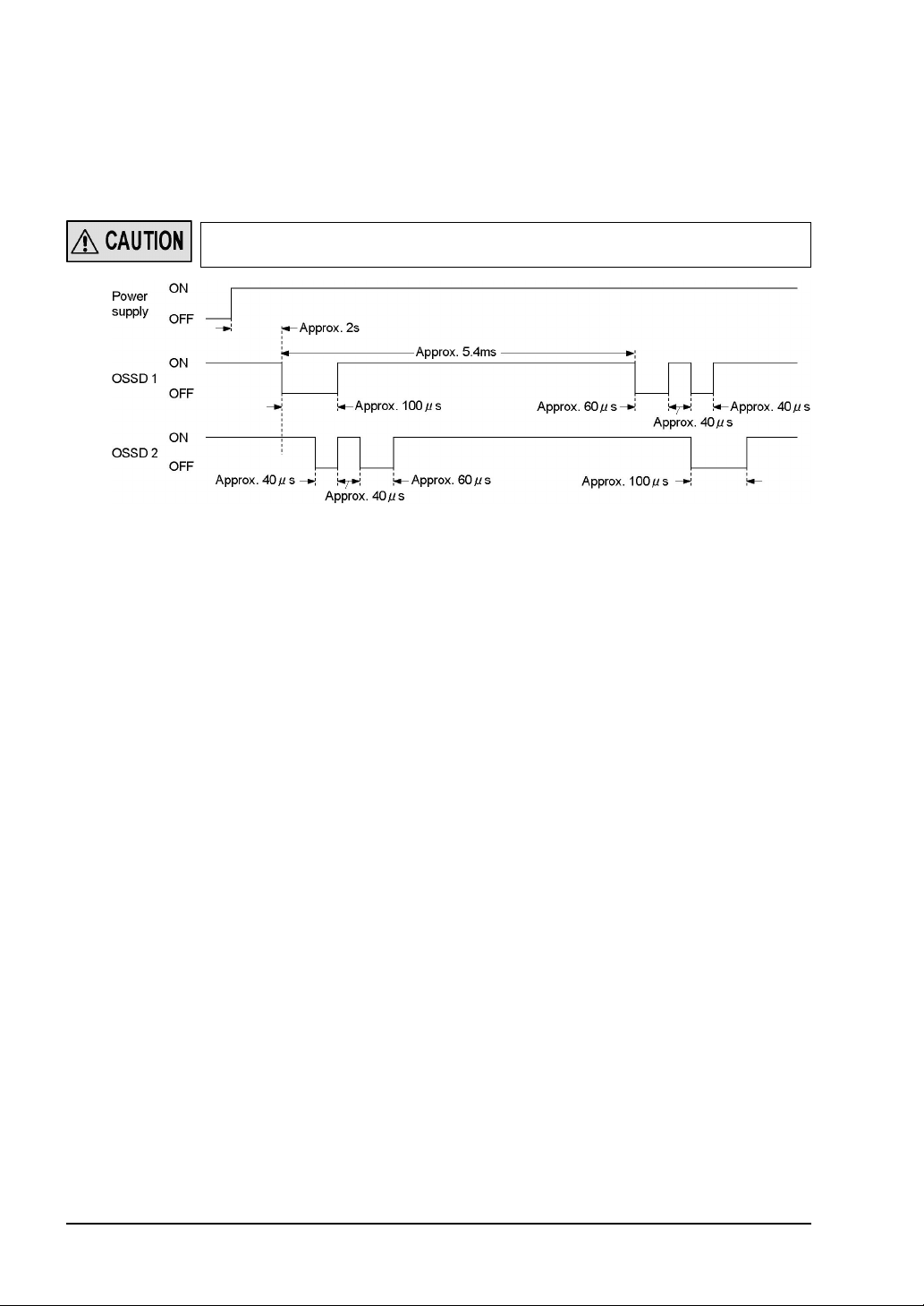
<Output waveform [control output (OSSD 1, OSSD 2) ON]>
Since the receiver performs the self-diagnosis of the output circuit when the sensor is in light
receiving status (ON status), the output transistor becomes OFF status periodically. (Refer to
the figure below.)
When the OFF signal is fed back, the receiver judges the output circuit as normal. When the
OFF signal is not fed back, the receiver judges either the output circuit or wiring as error, and
the control output (OSSD 1, OSSD 2) maintains OFF status.
Since the OFF signal of this device might cause malfunction, perform the connecting paying
attention to the input response time of the machine to be connected to this device.
- 36 -
SUNX Limited MJE-SF4B01 No.0005-03V
2-5-3 Wiring㨯Connecting Procedure and Connector Pin Arrangement
r
t
e
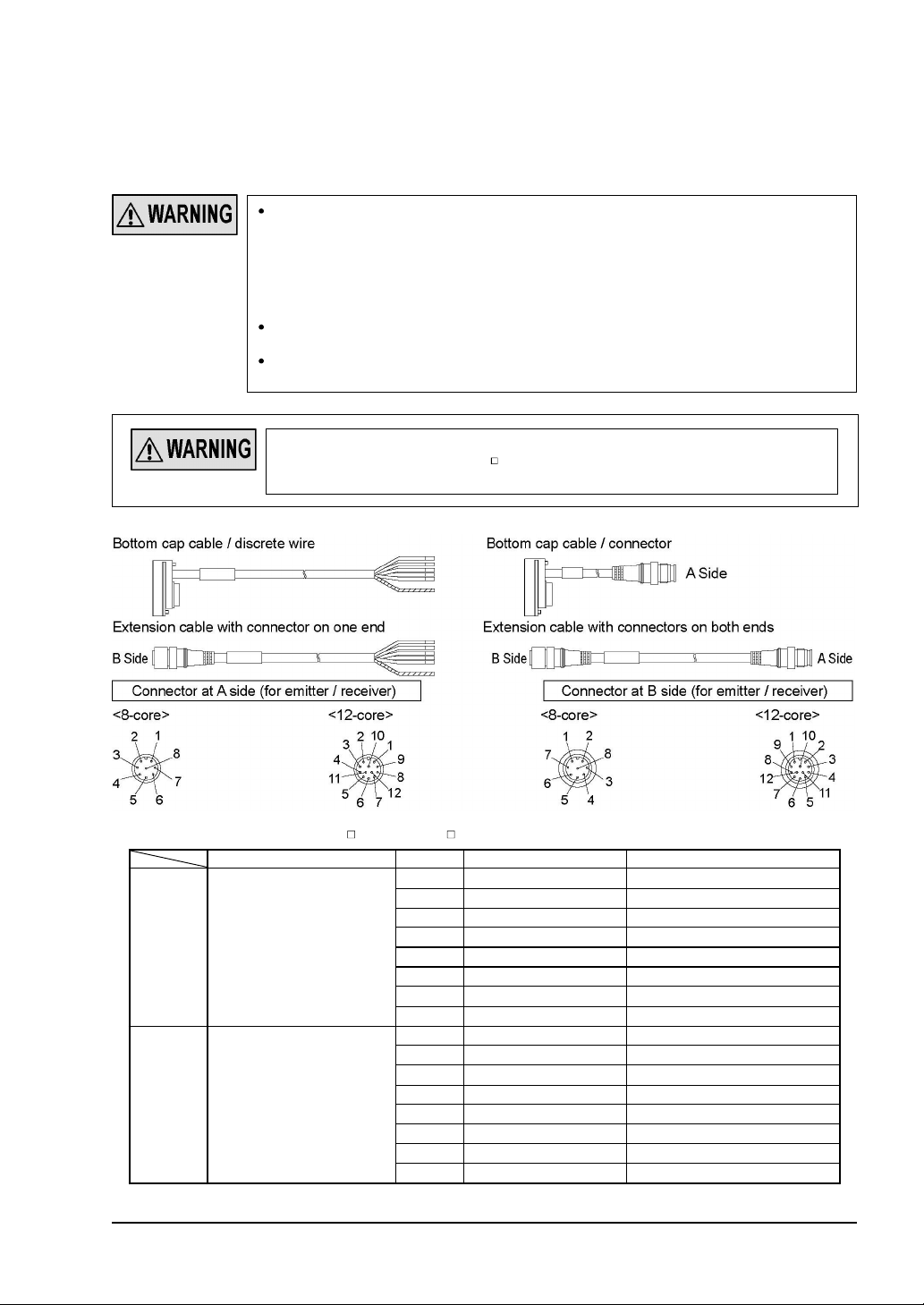
Connect the mating cable (with connector on one end, or connector on both ends) to the
connector of the sensor main body (emitter and receiver).
Wire the other side of the mating cable according to the customer’s application referring to the
connector pin arrangement given below.
When extending the cable, use the exclusive cable up to the total length of 50m (for emitte
/ receiver). Extending the cable longer than 50m may cause malfunction, which can resul
in serious injury or death. Besides, if the 2 sets of the sensors are connected in series, up
to total length of 30m (for emitter / receiver) is allowed for use, and if the 3 sets of the
sensors are connected, up to total length of 20m (for emitter / receiver) is allowed for use.
Extending the cable longer than the length specified may cause malfunction, which can
result in serious injury or death.
In case the muting lamp is used, a total length should be 40m or less. (for emitter / receiver)
When the synchronization cable is extended with a cable other than exclusive cable, use
a
Ǿ
0.2mm2 or more shielded twist pare cable.
When this device is used as safety equipment for press machines, be sure to use th
cable with protective tube (
2-4-4 Mounting of the Cable Protective Tube
refer to ‘
SFPB
- ). For mounting method of the cable protective tube,
’.
<8-core cable (SFB-CC / SFPB-CC )>
Cable / connector color Pin No. Lead wire color Description
1 Pale purple Interlock setting input
2 Brown 24V DC
3 Pink Emission halt input / Reset input
Emitter Gray / Gray
Receiver
Gray (with black stripe) /
Black
4 Yellow-green / Black Auxiliary output
5 Orange Synchronization +
6 Orange / Black Synchronization 7 Blue 0V
8 (Shield) Output polarity setting wire
1 White Control output 2 (OSSD 2)
2 Brown 24V DC
3 Black Control output 1 (OSSD 1)
4 Yellow-green External device monitor input
5 Orange Synchronization +
6 Orange / Black
7 Blue 0V
8 (Shield) Output polarity setting wire
Synchronization
SUNX Limited MJE-SF4B01 No.0005-03V
㧙
- 37 -
<12-core cable (SFB-CC -MU / SFPB-CC -MU)>
Cable / connector color Pin No. Lead wire color Description
1 Pale purple Interlock setting input
2 Brown 24V DC
3 Pink Emission halt input / Reset input
4 Yellow-green / Black Auxiliary output
5 Orange Synchronization +
Emitter Gray / Gray
Receiver
Gray (with black stripe) /
Black
6 Orange / Black Synchronization 7 Blue 0V
8 (Shield) Output polarity setting wire
9 Gray Interference prevention +
10 Gray / Black Interference prevention 11 Yellow Override input
12 Red Muting lamp output
1 White Control output 2 (OSSD 2)
2 Brown 24V DC
3 Black Control output 1 (OSSD 1)
4 Yellow-green External device monitor input
5 Orange Synchronization +
6 Orange / Black Synchronization -
7 Blue 0V
8 (Shield) Output polarity setting wire
9 Gray Interference prevention +
10 Gray / Black Interference prevention 11 Sky-blue / White Muting input A
12 Sky-blue / Black Muting input B
<Reference>
The connectors can be distinguished from their color as follows:
Connector for emitter: gray, connector for receiver: black
For details of the bottom cap cable, the cable with connector on one end, and the cable with connector on both
ends, refer to ‘
6-2 Options
’.
- 38 -
SUNX Limited MJE-SF4B01 No.0005-03V

2-5-4 Basic Wiring
This is the general configuration using one set of the emitter and receiver facing each other.
The control output (OSSD 1, OSSD 2) turns OFF if the light is blocked, while it automatically
turns ON if received the light.
The auxiliary output is used to invalid the external device monitor function. At this time, set
the auxiliary output with ‘negative logic of the control output’ (factory setting). The auxiliary
output cannot be connected to external devices.
<For PNP output>
Interlock function Invalid (Auto-reset)
External device monitor function Invalid
Auxiliary output Cannot be used
Note: The circuit diagram shown above is for 12-core cable to be used. For 8-core cable, red, yellow, grey, grey / black,
sky-blue / white, sky-blue / black, there is no lead wire.
SUNX Limited MJE-SF4B01 No.0005-03V
- 39 -

<For NPN output>
Interlock function Invalid (Auto-reset)
External device monitor function Invalid
Auxiliary output Cannot be used
Note: The circuit diagram shown above is for 12-core cable to be used. For 8-core cable, red, yellow, grey, grey / black,
sky-blue / white, sky-blue / black, there is no lead wire.
- 40 -
SUNX Limited MJE-SF4B01 No.0005-03V

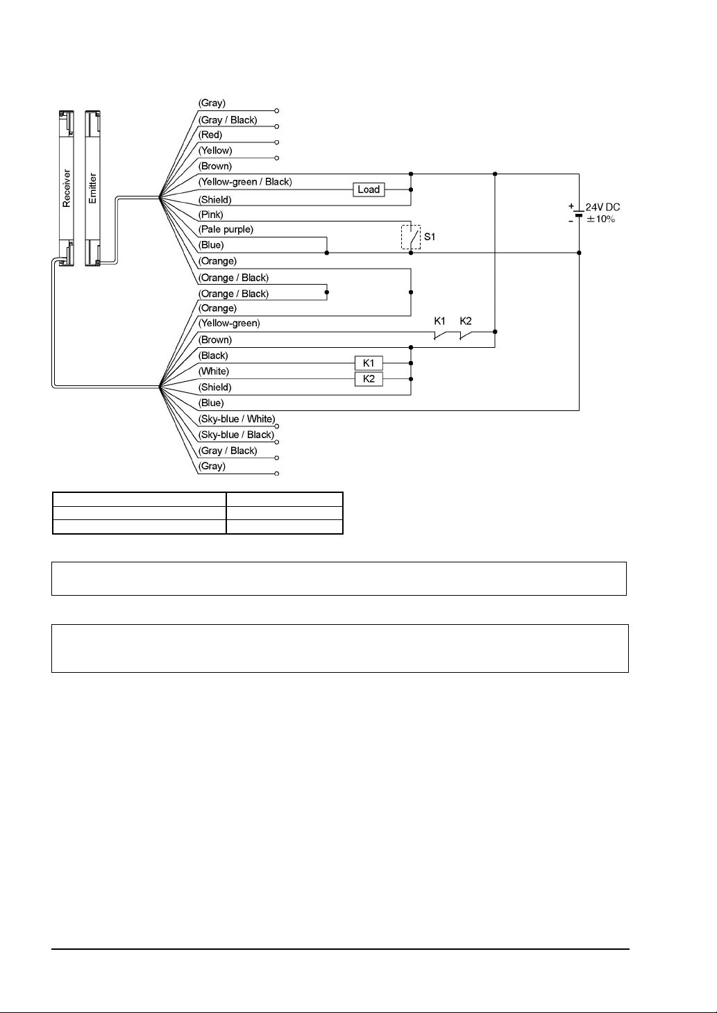
2-5-5 Wiring for Manual Reset (Interlock is Valid)
(Wiring Example of the Control Category 4)
This is the general configuration using one set of the emitter and receiver facing each other.
The control output (OSSD 1, OSSD 2) turns OFF if the light is blocked.
<For PNP output>
Interlock function Valid (Manual reset)
External device monitor function Valid
Auxiliary output Can be used
The sensor output is selected depending on the connecting state of the shield wire. Incorrect wiring may cause the
lockout state.
* Symbols
Switch S1
Vs to Vs - 2.5V (sink current 5mA or less): Emission halt (Note 1), Open: Emission
K1, K2: External device (Forced guided relay or magnetic contactor)
Notes: 1) Vs is the applying supply voltage.
2) The circuit diagram shown above is for 12-core cable to be used. For 8-core cable, red, yellow, grey, grey /
3) For resetting, refer to ‘
black, sky-blue / white, sky-blue / black, there is no lead wire.
3-2 Interlock Function
’.
SUNX Limited MJE-SF4B01 No.0005-03V
- 41 -
<For NPN output>
Interlock function Valid (Manual reset)
External device monitor function Valid
Auxiliary output Can be used
The sensor output is selected depending on the connecting state of the shield wire. Incorrect wiring may cause the
lockout state.
* Symbols
Switch S1
0 to +1.5V (source current 5mA or less): Emission halt, Open: Emission
K1, K2: External device (Forced guided relay or magnetic contactor)
Notes: 1) The circuit diagram shown above is for 12-core cable to be used. For 8-core cable, red, yellow, grey, grey /
2) For resetting, refer to ‘
black, sky-blue / white, sky-blue / black, there is no lead wire.
3-2 Interlock Function
’.
- 42 -
SUNX Limited MJE-SF4B01 No.0005-03V

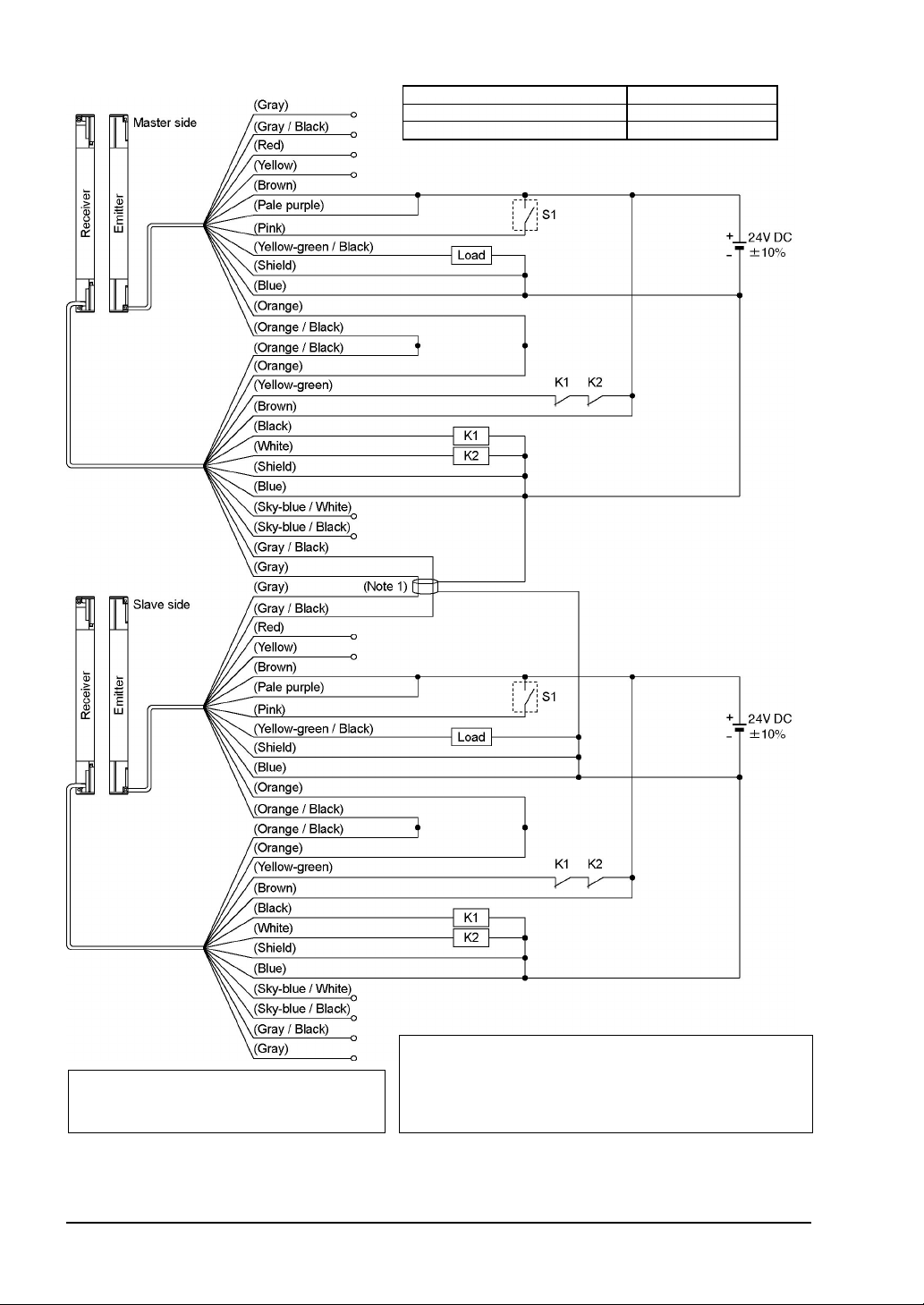
2-5-6 Series Connection
y
(Wiring Example of the Control Category 4)
[Connectable up to 3 sets of sensors (however, 192 beam channels max.)]
This is the configuration for connecting multiple sets of emitters and receivers facing each
other in series. It is used when the dangerous part can be entered from two or more directions. The control output (OSSD 1, OSSD 2) turns OFF if the light is blocked.
For series connection, connect the emitter and emitter, receiver and receiver respectivel
using the exclusive cable (
tion could generate the non-sensing area, resulting in serious injury or death.
<For PNP output>
SFB-CSL
/
SFPB-CSL
) for series connection. Wrong connec-
Interlock function Valid (Manual reset)
External device monitor function Valid
Auxiliary output Can be used
The sensor output is selected depending on the connecting state of the shield wire. Incorrect wiring may cause the
lockout state.
* Symbols
Switch S1
Vs to Vs - 2.5V (sink current 5mA or less): Emission halt (Note 1), Open: Emission
K1, K2: External device (Forced guided relay or magnetic contactor)
Notes: 1) Vs is the applying supply voltage.
2) The circuit diagram shown above is for 12-core cable to be used. For 8-core cable, red, yellow, grey, grey /
3) For resetting, refer to ‘
black, sky-blue / white, sky-blue / black, there is no lead wire.
3-2 Interlock Function
’.
SUNX Limited MJE-SF4B01 No.0005-03V
- 43 -

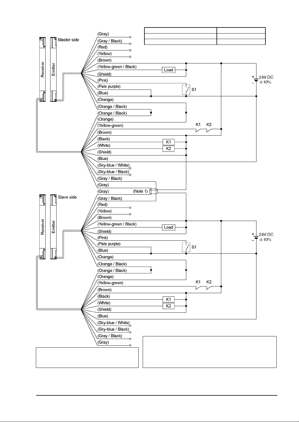
<For NPN output>
Interlock function Valid (Manual reset)
External device monitor function Valid
Auxiliary output Can be used
The sensor output is selected depending on the connecting state of the shield wire. Incorrect wiring may cause the
lockout state.
* Symbols
Switch S1
0 to +1.5V (source current 5mA or less): Emission halt, Open: Emission
K1, K2: External device (Forced guided relay or magnetic contactor)
Notes: 1) The circuit diagram shown above is for 12-core cable to be used. For 8-core cable, red, yellow, grey, grey /
2) For resetting, refer to ‘
black, sky-blue / white, sky-blue / black, there is no lead wire.
3-2 Interlock Function
’.
- 44 -
SUNX Limited MJE-SF4B01 No.0005-03V

2-5-7 Parallel Connection
(Wiring Example of the Control Category 4)
This is the configuration for connecting multiple sets of emitter and receiver facing each other
in parallel. It is used when there are two dangerous parts and each dangerous part can be
entered from only one direction. By connecting the interference prevention line, up to three
sets of the sensors can be connected. For the control output (OSSD 1, OSSD 2), only the
output of the sensor of which light is blocked turns OFF.
For parallel connection, connect the one receiver to the other connection using the interference prevention line as shown in the figure on the next page. Wrong connection could generate the non-sensing area, resulting in serious injury or death.
SUNX Limited MJE-SF4B01 No.0005-03V
- 45 -
<For PNP output>
Interlock function Valid (Manual reset)
External device monitor function Valid
Auxiliary output Can be used
* Symbols
Switch S1
Vs to Vs - 2.5V (sink current 5mA or less): Emission halt (Note 2)
The sensor output is selected depending on
the connecting state of the shield wire.
Incorrect wiring may cause the lockout state.
Notes: 1) If the interference prevention wire is extended, use a
2) Vs is the applying supply voltage.
3) For resetting, refer to ‘
3-2 Interlock Function
Open: Emission
K1, K2: External device
’.
- 46 -
(Forced guided relay or magnetic contactor)
Ǿ
0.2mm2, or more, shielded twisted pair-cable.
SUNX Limited MJE-SF4B01 No.0005-03V
<For NPN output>
Interlock function Valid (Manual reset)
External device monitor function Valid
Auxiliary output Can be used
* Symbols
Switch S1
0 to +1.5V (source current 5mA or less): Emission halt
The sensor output is selected depending on
the connecting state of the shield wire.
Incorrect wiring may cause the lockout state.
Notes: 1) If the interference prevention wire is extended, use a
2) For resetting, refer to ‘
3-2 Interlock Function
Open: Emission
K1, K2: External device
(Forced guided relay or magnetic contactor)
’.
SUNX Limited MJE-SF4B01 No.0005-03V
Ǿ
0.2mm2, or more, shielded twisted pair-cable.
- 47 -

2-5-8 Series and Parallel Mixed Connection
y
(Wiring Example of the Control Category 4)
This is the configuration for connecting multiple sets of emitter and receiver facing each other
in mixed series and parallel combination. It is used when there are two or more dangerous
parts that can be entered from two or more directions. Up to three sets of sensors in total of
the series connection and parallel connection can be connected in combination. However,
the total number of beam channels available is 192. The control output (OSSD 1, OSSD 2)
turns only its output to OFF if the light is blocked.
For series connection, connect the emitter and emitter, receiver and receiver respectivel
using the exclusive cable (
figure on the next page. Wrong connection could generate the non-sensing area, resulting
in serious injury or death.
For parallel connection, connect the one receiver to the other connection using the interference prevention line as shown in the figure on the next page. Wrong connection could
generate the non-sensing area, resulting in serious injury or death.
SFB-CSL
/
SFPB-CSL
) for series connection as shown in the
- 48 -
SUNX Limited MJE-SF4B01 No.0005-03V

<For PNP output>
Interlock function Valid (Manual reset)
External device monitor function Valid
Auxiliary output Can be used
* Symbols
Switch S1
Vs to Vs - 2.5V (sink current 5mA or less): Emission halt (Note 2)
The sensor output is selected depending on
the connecting state of the shield wire.
Incorrect wiring may cause the lockout state.
Notes: 1) If the interference prevention wire is extended, use a
2) Vs is the applying supply voltage.
3) For resetting, refer to ‘
3-2 Interlock Function
Open: Emission
K1, K2: External device
’.
SUNX Limited MJE-SF4B01 No.0005-03V
(Forced guided relay or magnetic contactor)
Ǿ
0.2mm2, or more, shielded twisted pair-cable.
- 49 -

<For NPN output>
Interlock function Valid (Manual reset)
External device monitor function Valid
Auxiliary output Can be used
* Symbols
Switch S1
0 to +1.5V (source current 5mA or less): Emission halt
The sensor output is selected depending on
the connecting state of the shield wire.
Incorrect wiring may cause the lockout state.
Notes: 1) If the interference prevention wire is extended, use a
2) For resetting, refer to ‘
3-2 Interlock Function
Open: Emission
K1, K2: External device
’.
- 50 -
(Forced guided relay or magnetic contactor)
Ǿ
0.2mm2, or more, shielded twisted pair-cable.
SUNX Limited MJE-SF4B01 No.0005-03V
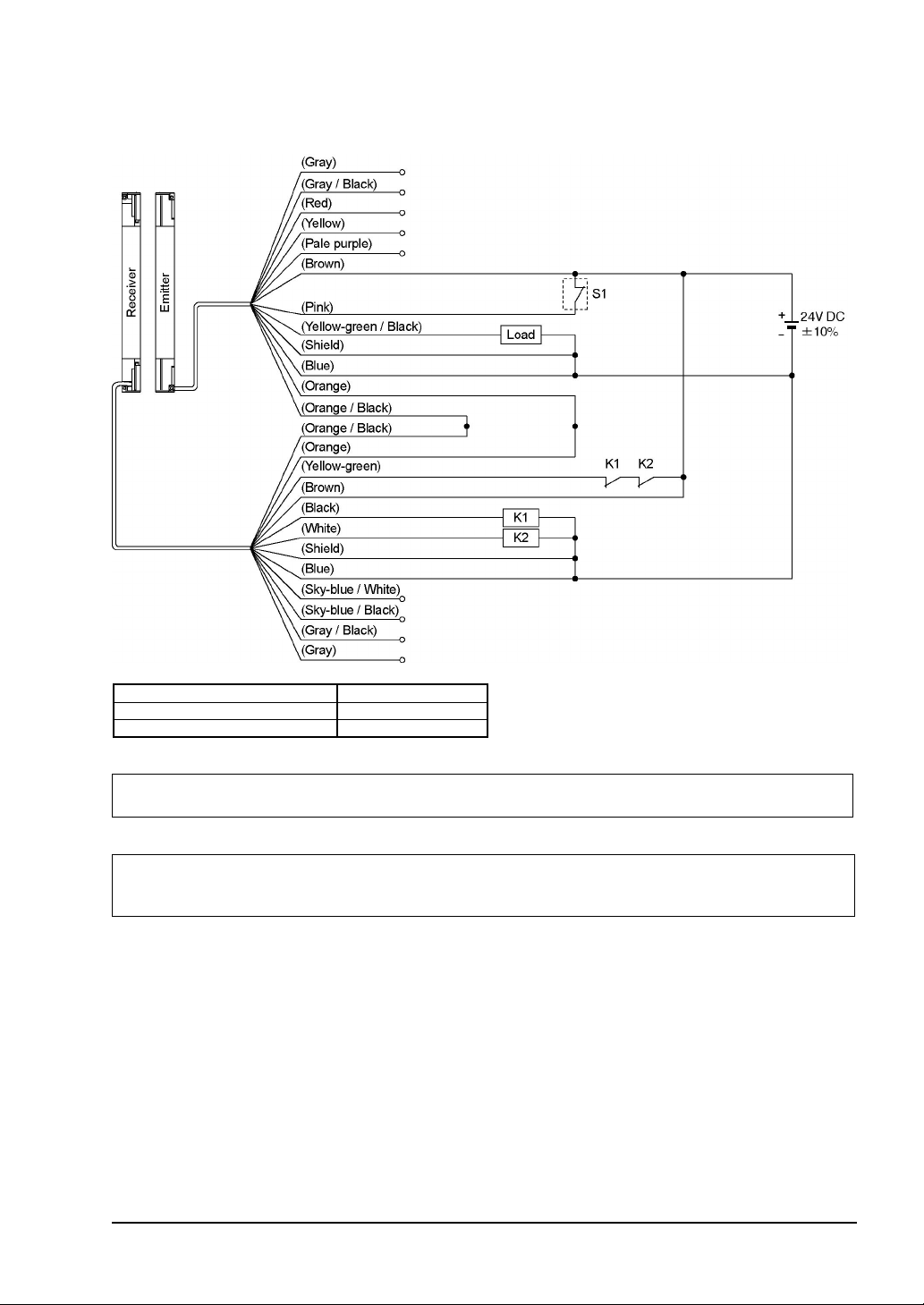
2-5-9 Wiring for Auto-reset (Interlock is Invalid)
(Wiring Example of the Control Category 4)
<For PNP output>
Interlock function Invalid (Auto-reset)
External device monitor function Valid
Auxiliary output Can be used
The sensor output is selected depending on the connecting state of the shield wire. Incorrect wiring may cause the
lockout state.
* Symbols
Switch S1
Vs to Vs - 2.5V (sink current 5mA or less): Emission (Note 1), Open: Emission halt
Note: Vs is the applying supply voltage.
K1, K2: External device (Forced guided relay or magnetic contactor)
Notes: 1) Vs is the applying supply voltage.
2) The circuit diagram shown above is for 12-core cable to be used. For 8-core cable, red, yellow, grey, grey /
3) For resetting, refer to ‘
black, sky-blue / white, sky-blue / black, there is no lead wire.
3-2 Interlock Function
’.
SUNX Limited MJE-SF4B01 No.0005-03V
- 51 -

<For NPN output>
Interlock function Invalid (Auto-reset)
External device monitor function Valid
Auxiliary output Can be used
The sensor output is selected depending on the connecting state of the shield wire. Incorrect wiring may cause the
lockout state.
* Symbols
Switch S1
0 to +1.5V (source current 5mA or less): Emission, Open: Emission halt
K1, K2: External device (Forced guided relay or magnetic contactor)
Notes: 1) The circuit diagram shown above is for 12-core cable to be used. For 8-core cable, red, yellow, grey, grey /
2) For resetting, refer to ‘
black, sky-blue / white, sky-blue / black, there is no lead wire.
3-2 Interlock Function
’.
- 52 -
SUNX Limited MJE-SF4B01 No.0005-03V

2-5-10 Wiring Configuration for Invalid External Device Monitor Function
(Wiring Example of the Control Category 4)
This is the configuration for connecting auxiliary output and external device monitor input.
At this time, set the auxiliary output with ‘negative logic of the control output (OSSD 1, OSSD
2)’ (factory setting). The auxiliary output cannot be connected to external devices.
<For PNP output>
Interlock function Invalid (Auto-reset)
External device monitor function Invalid
Auxiliary output Cannot be used
The sensor output is selected depending on the connecting state of the shield wire. Incorrect wiring may cause the
lockout state.
* Symbols
Switch S1
Vs to Vs - 2.5V (sink current 5mA or less): Emission (Note 1), Open: Emission halt
K1, K2: External device (Forced guided relay or magnetic contactor)
Notes: 1) Vs is the applying supply voltage.
2) The circuit diagram shown above is for 12-core cable to be used. For 8-core cable, red, yellow, grey, grey /
black, sky-blue / white, sky-blue / black, there is no lead wire.
SUNX Limited MJE-SF4B01 No.0005-03V
- 53 -
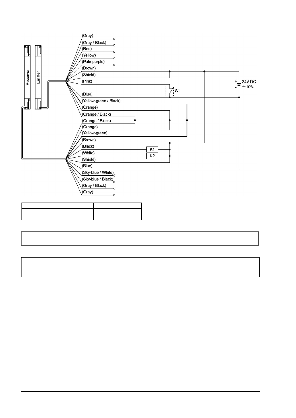
<For NPN output>
Interlock function Invalid (Auto-reset)
External device monitor function Invalid
Auxiliary output Cannot be used
The sensor output is selected depending on the connecting state of the shield wire. Incorrect wiring may cause the
lockout state.
* Symbols
Switch S1
0 to +1.5V (source current 5mA or less): Emission, Open: Emission halt
K1, K2: External device (Forced guided relay or magnetic contactor)
Note: The circuit diagram shown above is for 12-core cable to be used. For 8-core cable, red, yellow, grey, grey / black,
sky-blue / white, sky-blue / black, there is no lead wire.
- 54 -
SUNX Limited MJE-SF4B01 No.0005-03V

2-5-11 Connection Configuration for Valid Muting Function
(Wiring Example of the Control Category 4)
<For PNP output>
Interlock function Invalid (Auto-reset)
External device monitor function Valid
Auxiliary output Can be used
The sensor output is selected depending on the connecting state of the shield wire. Incorrect wiring may cause the
lockout state.
* Symbols
Switch S1
Vs to Vs - 2.5V (sink current 5mA or less): Emission (Note 2), Open: Emission halt
Switch S2
The muting input, the override input
Vs to Vs - 2.5V (sink current 5mA or less): Valid (Note 2), Open: Invalid
Notes: 1) The incandescent lamp with 3 to 10W shall be connected to the muting lamp output. If the muting lamp is
2) Vs is the applying supply voltage.
not connected, the muting function does not operate.
SUNX Limited MJE-SF4B01 No.0005-03V
- 55 -

<For NPN output>
Interlock function Invalid (Auto-reset)
External device monitor function Valid
Auxiliary output Can be used
The sensor output is selected depending on the connecting state of the shield wire. Incorrect wiring may cause the
lockout state.
* Symbols
Switch S1
0 to +1.5V (source current 5mA or less): Emission, Open: Emission halt
Switch S2
The muting input, the override input
0 to +1.5V (source current 5mA or less): Valid, Open: Invalid
Note: The incandescent lamp with 3 to 10W shall be connected to the muting lamp output. If the muting lamp is not
connected, the muting function does not operate.
- 56 -
SUNX Limited MJE-SF4B01 No.0005-03V

2-6
Adjustment
2-6-1 Beam-axis Alignment
1. Turn ON the power supply unit of this device.
2. Check that the digital error indicator (red) and the fault indicator (yellow) of the emitter and
receiver are off respectively.
If the digital error indicator (red) or the fault indicator (yellow) lights up or blinks, refer to
Chapter 5 Troubleshooting
‘
3. In case of using the intermediate supporting bracket (
gon-socket head bolt [M5 (please arrange separately)].
4. In case of using the standard mounting bracket (
sensor, loosen the two hexagon-socket head bolt for alignment of the standard mounting
bracket so that the emitter and receiver face to each other.
The marks are engraved on the standard mounting bracket A, which enables the angle of
the emitter / receiver to be adjusted by 30 degrees.
5. Tighten the hexagon-socket head bolt for alignment of the standard mounting bracket.
The tightening torque should be 2N
6. Loosen the hexagon-socket head bolt for beam axis alignment of the standard mounting
bracket, and adjust the emitter / receiver so that the beam-axis alignment indicators in the
display of the emitter and receiver light up.
The emitter and the receiver can be fine-adjusted by ±15 degrees.
’, and report the symptoms to the maintenance in charge.
㨯
m or less.
MS-SFB-2
MS-SFB-1
), loosen the two hexa-
) (optional) for mounting this
SUNX Limited MJE-SF4B01 No.0005-03V
- 57 -

<Reference>
The beam-axis alignment indicator indicates the reception status for each section of a sensor which is divided
into 4 sections.
Also, the A (D) of the beam-axis alignment indicates the light-receiving status of the sensor top end (bottom end).
For example, when using a 24-beam channel sensor, there are 6 beam channels per section (i.e., 24/4=6).
When the top end (bottom end) beam channel is received, the A (D) of the beam-axis alignment indicator blinks
in red.
(Example) 24 beam channels
All the 6 beam channels divided into each section are received, the bam-axis alignment indicator lights up in red.
The indicators corresponding to the different sections light up in red, one by one, when the beam channels of the
respective sections are received. When all the beam channels are received and the control output (OSSD 1,
OSSD 2) turns ON, all the four indicators of the beam-axis alignment indicator turn into green.
Refer to ‘
2-6-3 Operation
’ for details.
7. After the adjustment, tighten the hexagon-socket head bolt for beam axis alignment of the
standard mounting bracket. The tightening torque should be 2N
㨯
m or less.
8. Tighten the two intermediate supporting brackets [M5 (please arrange separately)].
Check, once again, that the beam-axis alignment indicators in the display of the emitter
and receiver do light up.
SUNX Limited MJE-SF4B01 No.0005-03V
- 58 -

2-6-2 Operation Test
1. Turn ON the power supply unit of this device.
2. Check that the digital error indicator (red) and the fault indicator (yellow) of the emitter and
the receiver are off respectively.
If the digital error indicator (red) or the fault indicator (yellow) lights up or blinks, refer to
‘
Chapter 5 Troubleshooting
3. Move the test rod up and down at three positions, just in front of the emitter (A), between
the emitter and receiver (B), and just in front of the receiver (C).
’, and report the contents to the maintenance in charge.
4. During Step 3 above, check that the control output (OSSD 1, OSSD 2) is in OFF state,
and both the OSSD indicator (red) of the receiver and the operation indicator (red) of the
emitter light up as long as the test rod is present within the sensing area.
If the behavior of the control output (OSSD 1, OSSD 2) and the turning ON / OFF of the
emitter / receiver indicators do not correspond to the movement of the test rod, refer to
Chapter 5 Troubleshooting
‘
<Reference>
If the indicators show reception of the light even though the test rod blocks the light, check whether there is any
reflective object or extraneous light source near this device or not.
’, and report the contents to the maintenance in charge.
When using this device as safety equipment for press machines in Japan, always observe the
following items and correctly use the device.
Secure a safety distance according to the maximum stopping time of the press machine.
Start the press machine, and confirm that the slide stops when the light is blocked.
Make sure that the receiver is not subject to direct sunlight.
When using an ‘rise disabled circuit’ having a function that does not suddenly stop the slide
even if the light is blocked while the slide is rising (the muting function), make sure that the
safety equipment is enabled when the slide is going down and is disabled only when rising.
Adjust the emitter, receiver and reflective plates so that none of the operator body parts,
depending on the work or work posture, etc., could enter the danger areas from either
above the uppermost beam channel or below the lowermost beam channel.
Refer to ‘Policy on Press Machine Safety Equipment Control’ (Ministry of Health, Labor and Welfare,
Basic Publication No.446-2, issued on July 9, 1993) for details.
SUNX Limited MJE-SF4B01 No.0005-03V
- 59 -
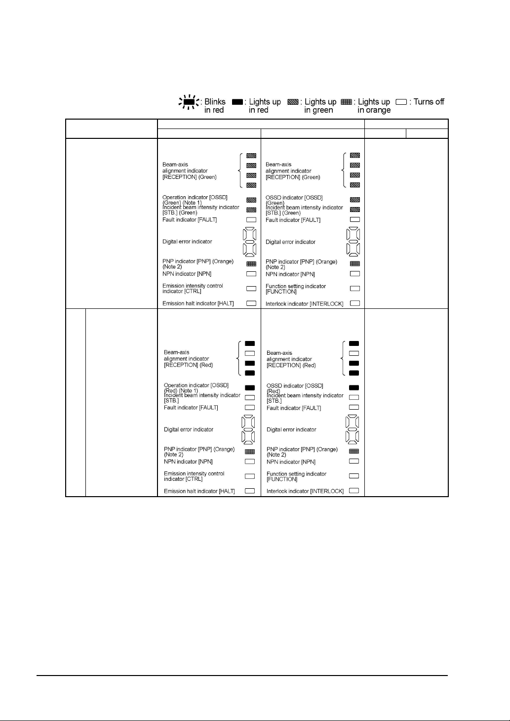
2-6-3 Operation
1) Normal Operation
The status of the emitter / receiver indicators during normal operation is as described below.
Device status
Beam received status
(all beams received)
One or more
beams
blocked
Emitter Receiver OSSD 1 OSSD 2
Indicators Control output
Lights up in green
Lights up in red
(OFF for beam blocked
channels)
Lights up in green
ON
Lights up in red
(OFF for beam blocked
channels)
OFF
Beam blocked status
Notes: 1) Since the color of the operation indicator changes according to the ON / OFF state of the control
2) The status of the emitter / receiver indicators during operation above shows the case in PNP output
output (OSSD 1, OSSD 2), the operation indicator is marked as OSSD on the sensor.
setting mode. In case of NPN output setting mode, the NPN indicator (orange) lights up.
SUNX Limited MJE-SF4B01 No.0005-03V
- 60 -

Device status
Beams other than
the top end blocked
Emitter Receiver OSSD 1 OSSD 2
Indicators Control output
The top most beam-axis
alignment indicator:
Blinks in red
Operation indicator:
Lights up in red
The top most beam-axis
alignment indicator:
Blinks in red
OSSD indicator:
Lights up in red
Beam blocked status
Beams other than
the bottom end
blocked
Time chart
The bottom most beam
-axis alignment indicator:
Blinks in red
Operation indicator:
Lights up in red
The bottom most beam
OFF
-axis alignment indicator:
Blinks in red
OSSD indicator:
Lights up in red
Notes: 1) Since the color of the operation indicator changes according to the ON / OFF state of the control
2) The status of the emitter / receiver indicators during operation above shows the case in PNP
output (OSSD 1, OSSD 2), the operation indicator is marked as ‘OSSD’ on the sensor.
output setting mode. In case of NPN output setting mode, the NPN indicator (orange) lights up.
SUNX Limited MJE-SF4B01 No.0005-03V
- 61 -
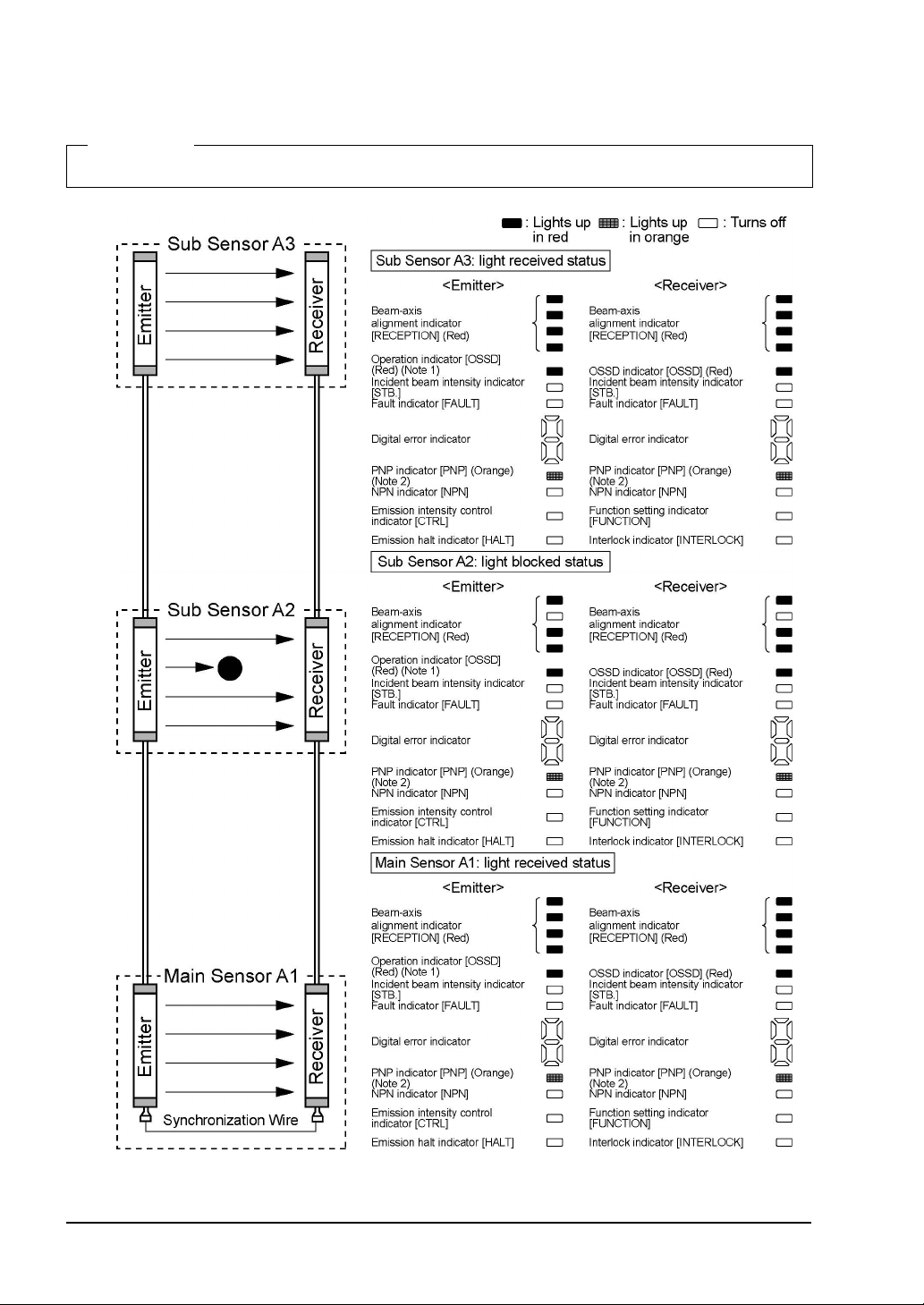
<For series connection>
In case of series connection, if any of the sets is in light blocked status, the control output
(OSSD 1, OSSD 2) turns OFF.
<Reference>
The emitter / receiver indicators indicate the output status.
The following figure shows the status of the indicators with Sub Sensor A2 in light blocked status.
Notes:1) Since the color of the operation indicator changes according to the ON / OFF state of the control
2) The status of the emitter / receiver indicators during operation above shows the case in PNP output
output (OSSD 1, OSSD 2), the operation indicator is marked as ‘OSSD’ on the sensor.
setting mode. In case of NPN output setting mode, the NPN indicator (orange) lights up.
SUNX Limited MJE-SF4B01 No.0005-03V
- 62 -
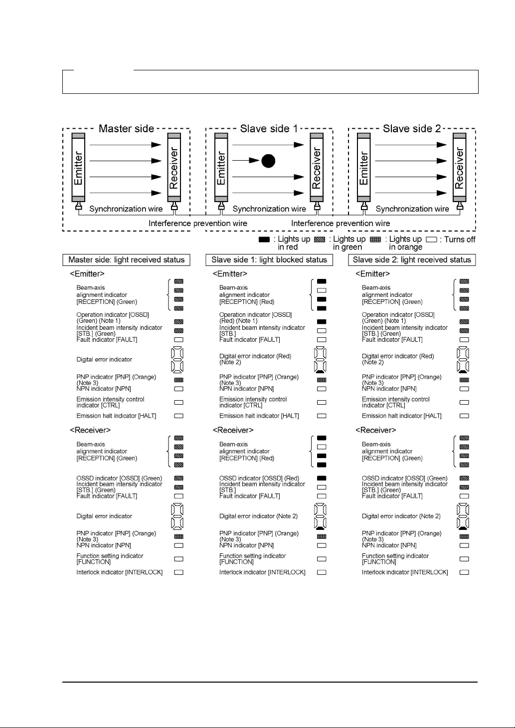
<For parallel connection>
In case of parallel connection, only the output of the sensor in light blocked status turns OFF.
<Reference>
The emitter / receiver indicators indicate the output status.
The following figure shows the status of the indicators with Slave side Sensor 1 in light
blocked status.
Notes: 1) Since the color of the operation indicator changes according to the ON / OFF state of the control output
2) When the sensors are connected in parallel, the bottom of the digital error indicator on the slave side lights
3) The status of the emitter / receiver indicators during operation above shows the case in PNP output setting
(OSSD 1, OSSD 2), the operation indicator is marked as ‘OSSD’ on the sensor.
up in red. However, when the slave side sensors are connected in series, only the indicator of the master
side sensor lights up.
mode. In case of NPN output setting mode, the NPN indicator (orange) lights up.
SUNX Limited MJE-SF4B01 No.0005-03V
- 63 -

2) When using emission halt function
This device incorporates the emission halt function. Using this function, it is possible to
simulate the beam blocked status.
<Reference>
When the emission halt input is kept open (for manual reset: connected to 0V, +V), the emitter stops emitting
light. In this condition, if this device operates properly, the control output (OSSD 1, OSSD 2) of the receiver turns
OFF.
check items
Before power is
ON
1
Connect the emission halt input to
Vs (Note 3)
After power is ON
Receiver’s control
2
output (OSSD 1,
OSSD 2) ON
(Normal operation)
Emitter Receiver OSSD 1 OSSD 2
Indicators Control output Setting procedure and
OFF
ON
Notes: 1) Since the color of the operation indicator changes according to the ON / OFF state of the control
2) The status of the emitter / receiver indicators during operation above shows the case in PNP
3) Vs is the applying supply voltage.
output (OSSD 1, OSSD 2), the operation indicator is marked as ‘OSSD’ on the sensor.
output setting mode. In case of NPN output setting mode, the NPN indicator (orange) lights up.
SUNX Limited MJE-SF4B01 No.0005-03V
- 64 -

check items
Open the emission
halt input
Receiver’s control
3
output (OSSD 1,
OSSD 2) is OFF
(Emission halt)
(Normal operation)
Connect the emission halt input to
Vs (Note 3)
4
Receiver’s control
output (OSSD 1,
OSSD 2) is ON
(Normal operation)
Emitter Receiver OSSD 1 OSSD 2
Indicators Control output Setting procedure and
OFF
ON
Notes: 1) Since the color of the operation indicator changes according to the ON / OFF state of the control
2) The status of the emitter / receiver indicators during operation above shows the case in PNP
3) Vs is the applying supply voltage.
output (OSSD 1, OSSD 2), the operation indicator is marked as ‘OSSD’ on the sensor.
output setting mode. In case of NPN output setting mode, the NPN indicator (orange) lights up.
SUNX Limited MJE-SF4B01 No.0005-03V
- 65 -

3) When an error occurs
If a sensor error is detected, the sensor will turn the control output (OSSD 1, OSSD 2) off and
the digital error indicator (red) on the receiver lights up and the fault indicator (yellow) on the
emitter and receiver light up or blinks.
If an emitter error is detected, the emitter will be locked out, stopping its emission, and
the control output (OSSD 1, OSSD 2) will be turned OFF.
If a receiver error is detected, the receiver will be locked out, and the control output
(OSSD 1, OSSD 2) will go into OFF state. Also, the emission halt indicator (orange) of the
emitter blinks.
<Emitter> <Receiver>
Notes: 1) Since the color of the operation indicator changes according to the ON / OFF state of the control
2) Refer to
3) The status of the emitter / receiver indicators during operation above shows the case in PNP output
Since this device will not return to normal operation automatically after the removal of the
source of error, it is necessary to turn the power off and on again.
(Source of error): The control output (OSSD 1, OSSD 2) short-circuit, extraneous light de-
Refer to ‘
output (OSSD 1, OSSD 2), the operation indicator is marked as ‘OSSD’ on the sensor.
setting mode. In case of NPN output setting mode, the NPN indicator (orange) lights up.
‘Chapter 5 Troubleshooting
’ for details of the digital error indicator.
tection, sensor failure, etc.
Chapter 5 Troubleshooting
’ and remove the source of error.
- 66 -
SUNX Limited MJE-SF4B01 No.0005-03V

Chapter 3 Functions
f
3-1
Self-diagnosis Function
This device incorporates the self-diagnosis function.
The self-diagnosis is carried out when the power is turned ON and while the operation periodically.
In case an abnormality is detected during self-diagnosis, the device is put in the lockout state
at that instant, and the control output (OSSD 1, OSSD 2) is fixed at the OFF state. Refer to
‘
Chapter 5 Troubleshooting
3-2
Interlock Function
The selection of manual reset / auto reset is available by applying the interlock input wiring.
The interlock becomes available by selecting manual reset.
Input status
Interlock setting
Open Auto reset
0V, +V connection Manual reset
Setting for interlock function
Manual reset : The control output (OSSD 1, OSSD 2) is not turned ON automatically even
though this device is received the light. When this device is reset in light received state [open the emission halt input / reset input
vice to 0V or +V
’ and remove the cause of the abnormality.
short-circuit the de-
open], the control output (OSSD 1, OSSD 2) is turned ON.
Auto-reset: The control output (OSSD 1, OSSD 2) is turned ON automatically when this
device receives the light.
If this device is used with the auto-reset, avoid an auto-restart after the safety output stop o
the system by using a safety relay unit etc. (EN 60204-1)
SUNX Limited MJE-SF4B01 No.0005-03V
- 67 -
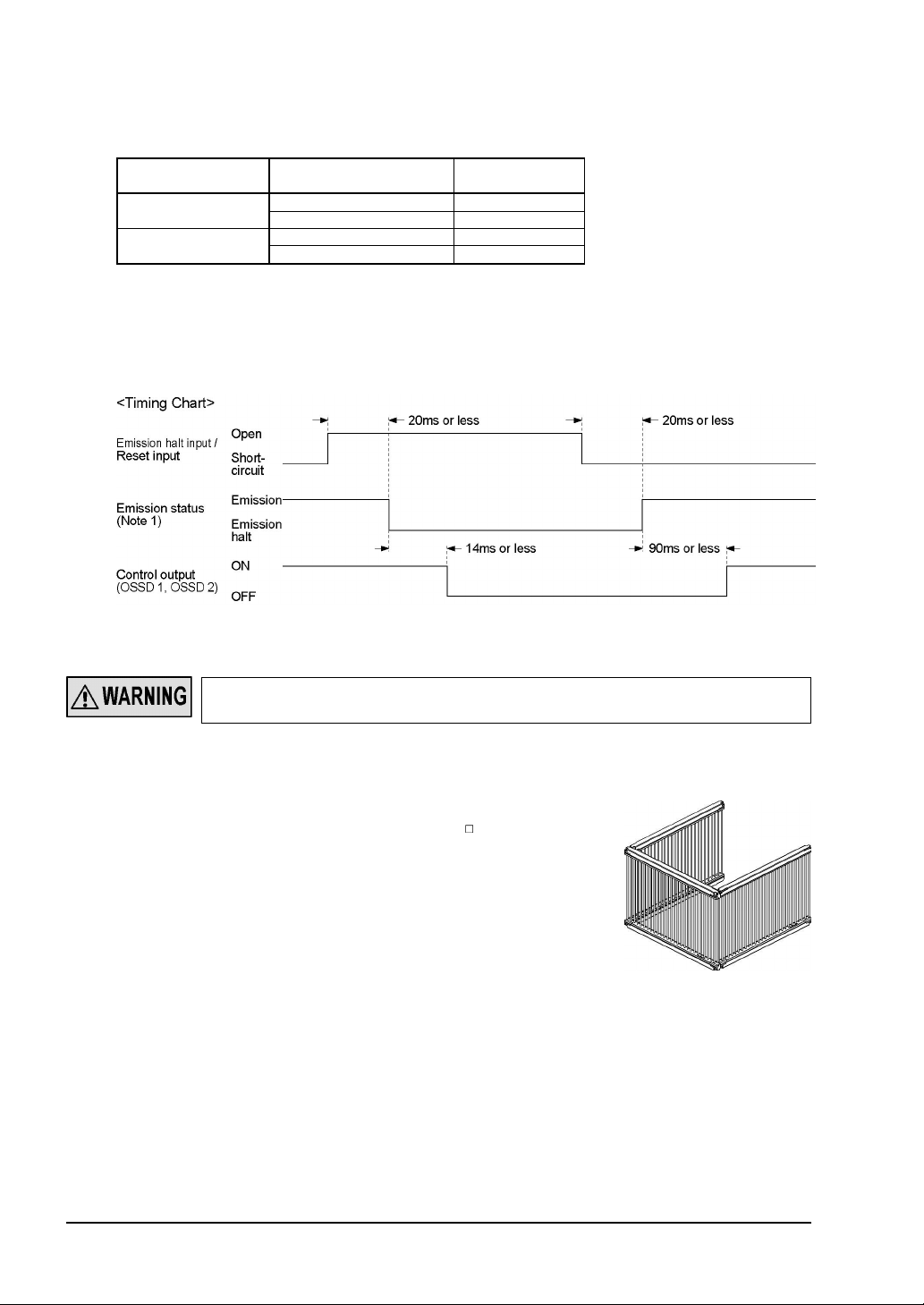
3-3
Emission Halt Function
This function stops the emission process of the emitter.
With the emission halt input line state, it enables to select either emission or emission halt.
Setting status of
interlock function
Auto reset
Manual reset
Emission halt input /
Reset input
Open Emission halt
0V, +V connection Emission
Open Emission
0V, +V connection Emission halt
Emission status
During emission halt, the control output (OSSD 1, OSSD 2) becomes OFF state.
By using this function, malfunction due to extraneous noise or abnormality in the control
output (OSSD 1, OSSD 2) and the auxiliary output can be determined even from the
equipment side.
Normal operation is restored when the emission halt input / reset input is connected to 0V or
+V (for manual reset: open).
Note: This timing chart shows the operation in auto-reset mode. In manual reset mode, the device performs
emission under open status and performs emission halt under short-circuit status.
Do not use the emission halt function for the purpose of stopping the device. Failure to do so
could result in serious injury or death.
3-4
Interference Prevention Function
It is possible to construct the system to prevent malfunction
due to interference of the light between
SF4B- -01
devices.
The interference prevention system can construct max. three
sets of series connection.
The max. number of the beam channels in series connection
is 192.
Refer to ‘
2-5 Wiring
’ for details of the connecting method.
- 68 -
SUNX Limited MJE-SF4B01 No.0005-03V

3-5
Auxiliary Output (Non-safety Output)
This device incorporates the auxiliary output for the non-safety output.
The auxiliary output is incorporated with the emitter.
Auxiliary output setting
Negative logic of OSSD
(Factory setting)
Do not use the auxiliary output for the purpose of stopping the device. Failure to do so could
result in serious injury or death.
3-6
External Device Monitor Function
Emission halt
ON OFF ON ON
Normal mode
Control output (OSSD 1, OSSD 2) status
Beam received Beam blocked
Lockout
This is the function for checking whether the external safety relay connected to the control
output (OSSD 1, OSSD 2) performs normally in accordance with the control output (OSSD 1,
OSSD 2) or not. Monitor the contacting point ‘b’ of the external safety relay, and if any abnormality such as deposit of the contacting point, etc. is detected, change the status of the
sensor into lockout one, and turn OFF the control output (OSSD 1, OSSD 2).
When the external device monitor function is set to be valid:
Connect the external device monitor input line to the external safety relay connected the
control output (OSSD 1, OSSD 2).
When the external device monitor function is set to be invalid:
Connect the external device monitor input line to the auxiliary output line. At this time, the
auxiliary output is set as [negative logic of control output (OSSD 1, OSSD 2)] (factory
setting). The auxiliary output cannot be connected to external devices.
The setting time of the device monitor is 300ms or less. Exceeding 300ms turns the device
into lockout status.
SUNX Limited MJE-SF4B01 No.0005-03V
- 69 -

3-7
y
k
Muting Function
Incorrect using of the muting control may cause any accident. Please understand the
muting control fully, and use it. As for the muting control, the following international standards define the requirements.
ISO 13849-1 (EN 954-1 / JIS B 9705-1):
‘Safety of machinery -- Safety-related parts of control systems -- Part 1: General principles
for design, Article 5.9 Muting’
IEC 61496-1 (UL 61496 / JIS B 9704-1):
‘Safety of machinery -- Electro sensitive protective equipment -- Part 1: General requirements and tests’ Annex A, A.7 Muting
IEC 60204-1 (JIS B 9960-1):
‘Safety of machinery -- Electrical equipment of machines - Part 1: General requirements,
9.2.4 Overriding safeguards’
EN 415-4:
‘Safety of packaging machines part 4. Palletizers and depalletizers’ Annex A, A2.2 Muting’
ANSI B11.19-1990:
‘for Machine Tools-Safeguarding When Referenced by the Other B11 Machine Tool Safet
Standards-Performance Criteria for the Design, Construction, Care, and Operation’ 4.2.3
Presence-Sensing Devices: Electro-Optical and Radio Frequency (R.F.)
ANSI/RIA R15.06-1999:
‘for Industrial Robots and Robot Systems - Safety Requirements, 10.4.5 Muting’
Use the muting control while the machine cycle is not in danger mode. Maintain safety with
the other measure while the muting control is activated.
For the application that the muting control is activated when a workpiece passes through
the sensor, place the muting sensor so that the conditions for the muting control cannot be
satisfied by intrusion of personnel when the workpiece is passing through the sensor or the
workpiece is not passing through it.
The muting lamp should be installed in a position where it can always be seen by operators
who set or adjust the machine.
Be sure to check the operation of the muting function before its use. Furthermore, chec
the state of the muting lamp (cleanliness or brightness etc.)
- 70 -
SUNX Limited MJE-SF4B01 No.0005-03V

This function turns the safety function of this device into invalid temporarily. When the control
output (OSSD 1, OSSD 2) is ON, this function is available for passing the workpiece through
the sensing area of the sensor without stopping the device.
The muting function becomes valid when all the conditions listed below are satisfied:
The control output (OSSD 1, OSSD 2) shall be ON.
The incandescent lamp with 3 to 10W shall be connected to the muting lamp output.
The output of the muting sensors A, B, C, and D shall be changed from OFF (open) to
ON. At this time, the time difference occurred by changing the output of the muting
sensors A, B, C, and D into ON status shall be within 0.03 to 3 sec.
The following devices, photoelectric sensor with semiconductor output, inductive proximity
sensor, position switch on NO (Normal Open) contacting point, etc. are available for applying
to the muting sensor.
<Specification for muting sensor>
Performance with ON state Performance with OFF state
ON with beam non-received
status (photoelectric sensor, etc.)
ON with object approaching
status (inductive proximity sensor,
etc.)
ON with object contacted status
(position switch, etc.)
Be sure to use the muting sensor that satisfies the
above. If the other muting sensor not satisfying the specification above, the muting function
might become valid with the timing that the machine designer cannot expect and could
result in serious injury or death.
The muting lamp shall be connected without fail. The muting function is invalid for activating with the muting lamp not connected.
Output 0V or +V Open
<Specification for muting sensor>
<Installation condition of muting sensor>
1) Shorten the distances between muting
sensors A to C and between B to D than the
whole length of the sensing object.
2) The moving speed [S (m/s)] of the sensing
object to be passed through the muting
sensors A to B shall be 30ms to 3 sec.
Distance between A and B: S x 3 (s)
3) The moving speed [S (m/s)] of the sensing
object to be passed through the muting
sensors C to D shall be under 3 sec.
Distance between C and D: S x 3 (s)
SUNX Limited MJE-SF4B01 No.0005-03V
- 71 -
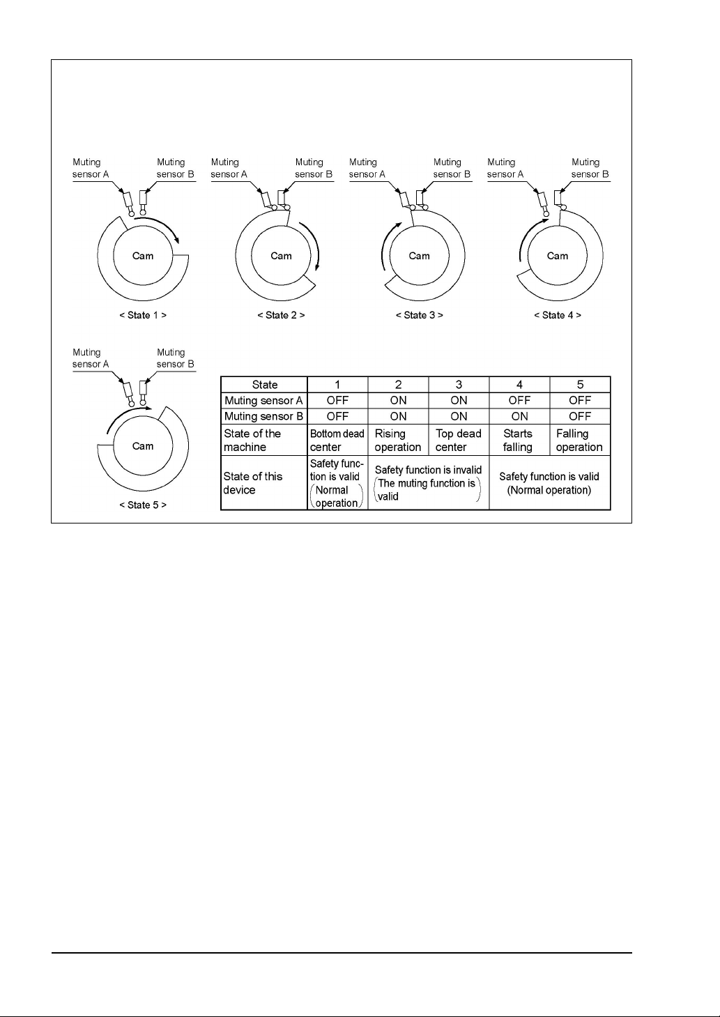
<Installation example for the muting sensors>
When this device is used as safety equipment for press machines in Japan, use it in the installing conditions as shown below.
However, the muting function can be used only when the slide is rising. For details, refer to
‘Standards for press machine or shears safety equipment structure’.
- 72 -
SUNX Limited MJE-SF4B01 No.0005-03V

Note: This is when the muting lamp diagnosis function is valid. If the muting lamp does not light up even if 1s is
passed, the muting function becomes invalid. When the muting lamp diagnosis function is invalid, the
muting function becomes valid 50ms after the input conditions of the muting sensor A (C) and B (D) were
satisfied.
<Reference>
It is recommended that two muting lamps should be connected in parallel. In this case, take care not to exceed
.
10W
SUNX Limited MJE-SF4B01 No.0005-03V
- 73 -

3-8
y
k
Override Function
Incorrect using of the muting control may cause any accident. Please understand the
muting control fully, and use it. As for the muting control, the following international standards define the requirements.
ISO 13849-1 (EN 954-1 / JIS B 9705-1):
‘Safety of machinery -- Safety-related parts of control systems -- Part 1: General principles
for design, Article 5.9 Muting’
IEC 61496-1 (UL 61496 / JIS B 9704-1):
‘Safety of machinery -- Electro sensitive protective equipment -- Part 1: General requirements and tests’ Annex A, A.7 Muting
IEC 60204-1 (JIS B 9960-1):
‘Safety of machinery -- Electrical equipment of machines - Part 1: General requirements,
9.2.4 Overriding safeguards’
EN 415-4:
‘Safety of packaging machines part 4. Palletizers and depalletizers’ Annex A, A2.2 Muting’
ANSI B11.19-1990:
‘for Machine Tools-Safeguarding When Referenced by the Other B11 Machine Tool Safet
Standards-Performance Criteria for the Design, Construction, Care, and Operation’ 4.2.3
Presence-Sensing Devices: Electro-Optical and Radio Frequency (R.F.)
ANSI/RIA R15.06-1999:
‘for Industrial Robots and Robot Systems - Safety Requirements, 10.4.5 Muting’
Use the muting control while the machine cycle is not in danger mode. Maintain safety with
the other measure while the muting control is activated.
For the application that the muting control is activated when a workpiece passes through
the sensor, place the muting sensor so that the conditions for the muting control cannot be
satisfied by intrusion of personnel when the workpiece is passing through the sensor or the
workpiece is not passing through it.
The muting lamp should be installed in a position where it can always be seen by operators
who set or adjust the machine.
Be sure to check the operation of the muting function before its use. Furthermore, chec
the state of the muting lamp (cleanliness or brightness etc.)
This function sets the safety function of this device invalid forcibly. This function is used for
the following cases: when the customer who uses the muting function needs to start the device with the control output (OSSD 1, OSSD 2) be OFF status, when the device is required to
continue operating even though the muting sensor becomes valid after the muting sensor is
turned ON at the starting of line.
The override function becomes valid when all the conditions listed below are satisfied:
The incandescent lamp with 3 to 10W shall be connected to the muting lamp output.
The signal shall be input to either muting sensor A or B.
The override input shall be short-circuited to 0V or +V, and the emission halt input / reset input shall be opened. (3 sec. continuously)
If one of the three conditions above becomes invalid or timing exceeds 60 sec., the override
function becomes invalid.
Note: The override function operates only when the auto-reset is ON (the interlock is invalid).
- 74 -
SUNX Limited MJE-SF4B01 No.0005-03V

Note: This is when the muting lamp diagnosis function is valid. If the muting lamp does not light up even if 1s is
passed, the override function becomes invalid. When the muting lamp diagnosis function is invalid, the
muting function becomes valid 3s after the input conditions of the muting sensor A (C) and B (D) were
satisfied.
SUNX Limited MJE-SF4B01 No.0005-03V
- 75 -

Chapter 4 Maintenance
r
<Reference>
When any errors are found, refer to ‘
charge. If the rectification method is not clear, please contact our office.
Please make a copy of this checklist, check each inspection item in the respective square, and file the list for
record.
4-1
Daily Inspection
Be sure to inspect the following items prior to operation and confirm that there is no error.
Operating this device without inspection or in an error condition can result in serious injury o
death.
Check list (Daily inspection)
Check
column
Dangerous parts of the machine cannot be reached without passing through the sensing area
of this device.
Some part of operator’s body remains in the sensing area when operation is done with dan-
gerous parts.
The calculated safety distance has been maintained or exceeded during installation.
There is no damage to the safety guard or protective structure.
There is no defect, fold, or damage in the wiring.
The corresponding connectors have been connected securely.
No dirt or scratches exist on the light emitting surface.
The test rod is not deformed or defective.
The operation indicator (green) of the emitter and the OSSD indicator (green) of the receiver
light up when no object is present in the sensing area. The control output (OSSD 1, OSSD 2)
is in ON status.
At this time, the effect of external noise can be inspected. In case external noise affects the
operation, remove its cause and re-inspect.
The test rod can be detected at three positions, directly in front of the emitter (A), midway
between the emitter and the receiver (B), and directly in front of the receiver (C).
The OSSD indicator (red) of the receiver and the operation indicator (red) of the emitter continue to light up as long as the test rod is present in the sensing area from (A) to (C).
Chapter 5 Troubleshooting
’ and report the contents to the maintenance in
Inspection item
- 76 -
With the machine in the operating condition, the dangerous parts operate normally when no
object is present in the sensing area.
With the machine in the operating condition, the dangerous parts stop immediately when the
test rod is inserted into the sensing area at any of the three positions, directly in front of the
emitter (A), midway between the emitter and the receiver (B), and directly in front of the receiver (C).
The dangerous parts remain stopped as long as the test rod is present in the sensing area.
The dangerous parts stop immediately when the power supply of this device is turned OFF.
The control output (OSSD 1, OSSD 2) must turn OFF when the emission halt input / reset
input line is open (for manual reset: connected to 0V, +V). At this time, the effect of external
noise can be inspected. In case external noise affects the operation, remove its cause and
re-inspect.
Be sure to check the operation of the muting function before its use. Furthermore, check the
state of the muting lamp (cleanliness or brightness etc.)
SUNX Limited MJE-SF4B01 No.0005-03V
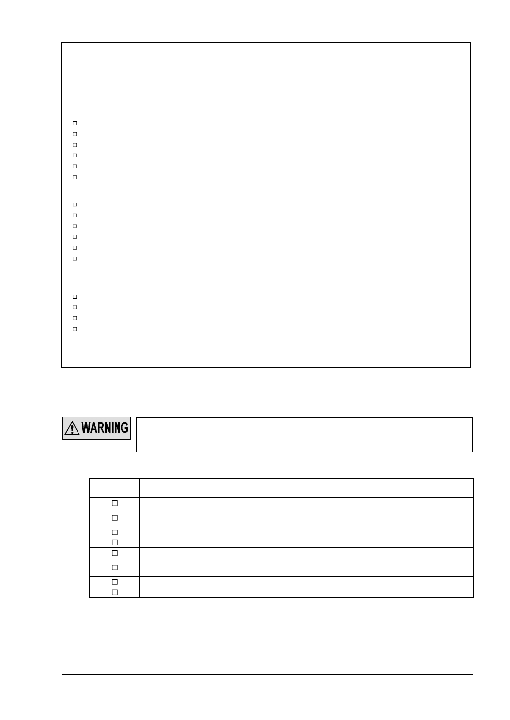
When this product is used as safety equipment for press machines in Japan, a pre-work in-
r
spection and periodic inspection must be carried out by the press machine work supervisor or
by the person in charge of the matters listed in Provision 134, No.1, 2 and 4 of the Ordinance
on Labor Safety and Hygiene. The press machine work supervisor, etc., must inspect the following matters before starting work, and must record and save the results.
Emitter of this device
Security of mounting
Adequacy of mounting position (safety distance and vertical position)
Presence of damage
Presence of abnormality in external wires
Presence of contamination on emitter
Security of detection state
Receiver of this device
Security of mounting
Adequacy of mounting position (safety distance and vertical position)
Presence of damage
Presence of abnormality in external wires
Presence of contamination on receiver
Security of detection state
Control unit SF-C11 / SF-C13
Application expansion unit SF-C14EX-01
External wiring
Indicators
Presence of abnormal operation with switches, etc.
Security of mounting
Refer to ‘Policy on Press Machine Safety Equipment Control’ (Ministry of Health, Labor and
Welfare, Basic Publication No.446-2, issued on July 9, 1993) for details.
4-2
Periodic Inspection (Every Six Months)
Be sure to inspect the following items every six months and confirm that there is no error.
Operating this device without inspection or in an error condition can result in serious injury o
death.
Check list (Period inspection)
Check
column
The structure of the machine does not obstruct any safety mechanism for stopping operation.
No modification has been made in the machine controls which obstructs the safety mecha-
nisms.
The output of this device is correctly detected.
The wiring from this device is correct.
The overall response time of the complete machine is equal or less than the calculated value.
The actual number of operation cycle (time) of the limited lifetime parts (relay, etc.) is less
than their rated operation cycles (time).
No screws or connectors of this device are loose.
No extraneous light source or reflective object has been added near this device.
SUNX Limited MJE-SF4B01 No.0005-03V
Inspection item
- 77 -

4-3
Inspection after Maintenance
Under the following situations, perform all the inspection items mentioned in ‘
spection
’ and ‘
4-2 Periodic Inspection (Every Six Months)
1) When any parts of this device are replaced.
2) When some abnormality is felt during operation.
3) When beam-axis alignment of the emitter and receiver is done.
4) When the device installation place or environment is changed.
5) When the wiring method or wiring layout is changed.
6) When FSD (Final Switching Device) parts are replaced.
7) When FSD (Final Switching Device) setting is changed.
’.
4-1 Daily In-
- 78 -
SUNX Limited MJE-SF4B01 No.0005-03V
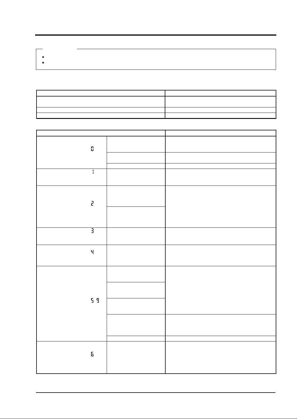
Chapter 5 Troubleshooting
<Reference>
Check the wiring.
Check the power supply voltage and the power supply capacity.
5-1
Troubleshooting of Emitter
<All indicators are OFF>
Cause Remedy
Power is not being supplied.
Supply voltage is out of the specified range. Set the supply voltage correctly.
Connector is not connected securely. Connect the connector securely.
<Fault indicator (yellow) lights or blinks>
Cause Remedy
Series connection is in-
[Digital error indicator: ]
Setting data of this device error
[Digital error indicator: ]
System between emitter and
receiver error
[Digital error indicator: ]
Series connection error
correct.
Noise is out of the specified range.
Internal error Replace this device.
Systems are different
between emitter and
receiver.
The serial signal
short-circuits or comes
down.
The other series connection sensor is in error.
Check that the power supply capacity is sufficient.
Connect the power supply correctly.
Check that the series connection cable does not
short-circuit, or is connected to the correct position
(emitter for emitter, receiver for receiver).
Check the noise status around this device.
Set the same value to the Nos. of emitter and receiver and that of beam channel, and the shield
wires.
Check if the end cap has been fitted properly.
Check that the series connection cable does not
short-circuit, or is connected to the correct position
(emitter for emitter, receiver for receiver).
Check the error contents of the sensor connected
by the series connection cable.
[Digital error indicator: ]
Total unit No. / total beam
channel No. error
[Digital error indicator: ]
Interlock setting error
[Digital error indicator: ,]
Muting lamp error
[Digital error indicator: ]
Shield wire error
Total unit No. / total beam
channel No. is out of the
specified range.
Voltage level of interlock
setting input wire, or
emission halt input / reset
input wire is unstable.
Muting lamp output
short-circuits with +V or
0V.
Muting lamp output
short-circuits with other
I/O wires.
Excessive incoming current flows in the muting
lamp output.
Output polarity setting
wire (shield) and muting
lamp output are not correctly wired.
Output circuit error Output circuit is damaged. Replace this device.
Shield wire comes down
or short-circuits with other
I/O wires.
Shield wire connection of
emitter / receiver is incorrect.
SUNX Limited MJE-SF4B01 No.0005-03V
Set the condition of the series connection within the
specification.
Refer to ‘
Wire the interlock setting input wire and emission
halt input / reset input wire correctly.
Wire the control output (OSSD 1, OSSD 2) wires
correctly.
Refer to ‘
Current value should be within the specified control
output (OSSD 1, OSSD 2).
Refer to ‘
Wire the output polarity setting wire (shield) correctly. (+V: NPN output, 0V: PNP output)
Wire the shield wire of the emitter correctly.
Wire the output polarity setting wire (shield) correctly. (+V: NPN output, 0V: PNP output)
Wire the shield wire of the receiver correctly.
2-5-6 Series Connection
2-5 Wiring
6-1 Specifications
’.
’.
’.
- 79 -
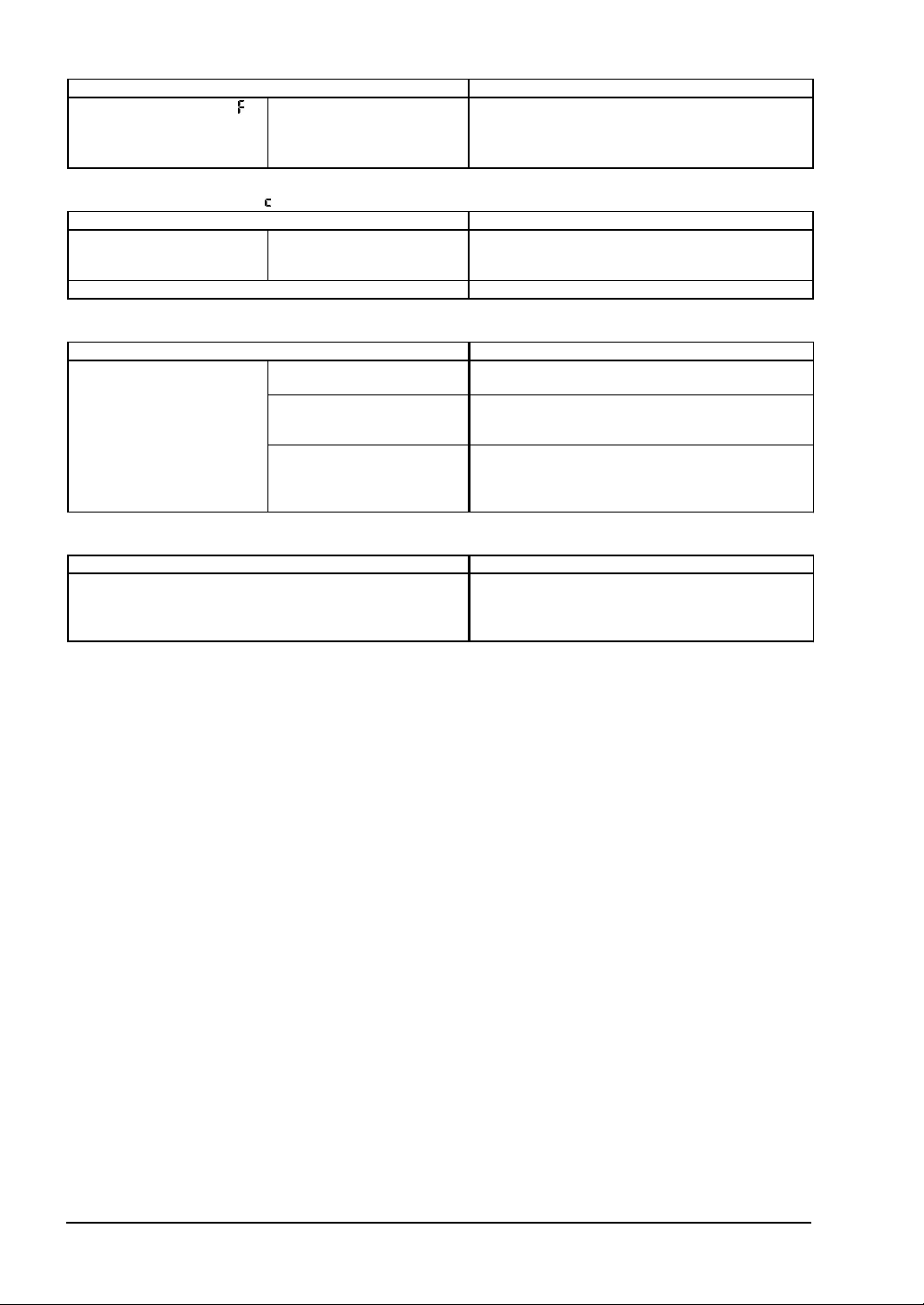
Cause Remedy
[Digital error indicator: ]
Effect from noise / power
supply or failure of internal
circuit
Affected by noise / power
supply.
Internal circuit is broken
down.
Check the noise status around this device.
Check the wiring status, supply voltage, and power
supply capacity.
Even if the error is not cleared, contact SUNX.
<Digital error indicator
Synchronization wire error
Receiver error Check the operation of the receiver side.
lights up>
Cause Remedy
Synchronization wire is
short-circuited or disconnected.
Connect the synchronization wire properly.
<Emission halt indicator (orange) lights up>
Cause Remedy
Emission is in halt condition
(Device error or interlock
setting error)
Error indicator (yellow) lights
or blinks.
Emission halt input / reset
input wire is open when selecting auto-reset.
Emission halt input / reset
input wire is connected to +V
or 0V when selecting manual
reset.
Check the contents of the digital error indicator.
Wire the emission halt input / reset input wire to 0V
or +V.
Refer to ‘
Open the emission halt input / reset input wire.
Refer to ‘
2-5 Wiring
2-5 Wiring
’.
’.
<Operation indicator remains lit in red (light is not received) (Note)>
Cause Remedy
Align the beam channels.
The beam channels are not correctly aligned.
Note: Since the color of the operation indicator changes according to ON / OFF status of the control output (OSSD 1,
OSSD 2), the operation indicator is marked as ‘OSSD’ on the sensor.
Refer to ‘
Align the top / bottom direction of the beam channel
between emitter and receiver.
2-6
Adjustment
’.
If the device does not work normally after checking the items above, please consult SUNX.
- 80 -
SUNX Limited MJE-SF4B01 No.0005-03V

5-2
Troubleshooting of Receiver
<All indicators are OFF>
Cause Remedy
Power is not being supplied.
Supply voltage is out of the specified range. Set the supply voltage correctly.
Connector is not connected securely. Connect the connector securely.
Check that the power supply capacity is sufficient.
Connect the power supply correctly.
<Fault indicator (yellow) lights or blinks>
Cause Remedy
Check that the series connection cable does not
short-circuit, or is connected to the correct position
(emitter for emitter, receiver for receiver).
Check the noise status around this device.
Set the same value to the Nos. of emitter and receiver and that of beam channel, and the shield
wires.
Check if the end cap has been fitted properly.
Check that the series connection cable does not
short-circuit, or is connected to the correct position
(emitter for emitter, receiver for receiver).
Check the error contents of the sensor connected
by the series connection cable.
[Digital error indicator: ]
Setting data of this device error
[Digital error indicator: ]
System between emitter and
receiver error
[Digital error indicator: ]
Series connection error
Series connection is incorrect.
Noise is out of the specified range.
Internal error Replace this device.
Systems are different
between emitter and receiver.
The serial signal
short-circuits or comes
down.
The other series connection sensor is in error.
[Digital error indicator: ]
Total unit No. / total beam
channel No. error
[Digital error indicator: ]
Extraneous light error
[Digital error indicator: ,]
Control output (OSSD 1, OSSD
2) error
[Digital error indicator: ]
Shield wire error
Total unit No. / total beam
channel No. is out of the
specified range.
Extraneous light is entering or light from other
model is entering.
OSSD 1 wire or OSSD 2
wire short-circuits with +V
or 0V.
Control output (OSSD 1,
OSSD 2)
short-circuit respectively,
or short-circuit with other
I/O wires.
Excessive incoming current flows in the
output (OSSD 1, OSSD 2)
wires.
Output polarity setting
wire (shield) and
output (OSSD 1, OSSD 2)
wires are not correctly
wired.
Output circuit error Output circuit is damaged. Replace this device.
Shield wire comes down or
short-circuits with other I/O
wires.
Shield wire connection of
emitter / receiver is incorrect.
wires
control
control
Set the condition of the series connection within the
specification.
Refer to ‘
When the power is ON, prevent any extraneous
light from entering the receiver.
If the extraneous light is coming from this device,
conduct ‘
Interference Prevention Function
Wire the control output (OSSD 1, OSSD 2) wires
correctly.
Refer to ‘
Current value should be within the specified control
output (OSSD 1, OSSD 2) wires.
Refer to ‘
Wire the output polarity setting wire (shield) correctly. (+V: NPN output, 0V: PNP output)
Wire the shield wire of the emitter correctly.
Wire the output polarity setting wire (shield) correctly. (+V: NPN output, 0V: PNP output)
Wire the shield wire of the receiver correctly.
2-5-6 Series Connection
2-3-4 Sensor Placement
2-5 Wiring
6-1 Specifications
’.
’.
’.
’ or ‘
’.
3-4
SUNX Limited MJE-SF4B01 No.0005-03V
- 81 -
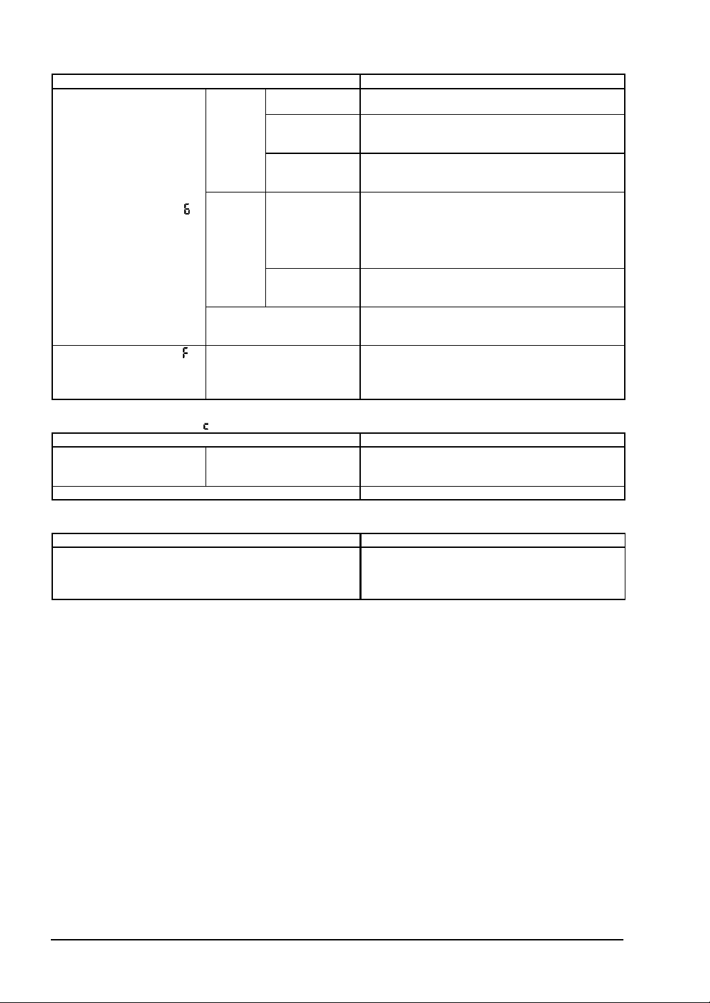
Cause Remedy
[Digital error indicator㧦 ]
External device error
[Digital error indicator: ]
Effect from noise / power
supply or failure of internal
circuit
Relay contact is
When
using
safety
relay
When
setting
the external
device
monitor
function
to ‘invalid’.
Bottom cap cables are adversely connected between
emitter and receiver.
Affected by noise / power
supply.
Internal circuit is broken
down.
welded.
Response time
of the relay is
slow.
Contacting point
‘b’ of the relay is
not wired.
Auxiliary output
wire and external device
monitor input
wire are not
wired.
Auxiliary output
is not correctly
operated.
Replace the relay.
Replace the relay with proper response time.
Refer to ‘
Wire correctly to the relay.
Connect the auxiliary output wire and the external
device monitor input wire.
Check if the auxiliary output wire is disconnected or
short-circuited.
Check the connecting locations of the bottom cap
cables.
Check the noise status around this device.
Check the wiring status, supply voltage, and power
supply capacity.
Even if the error is not cleared, contact SUNX.
3-6 External Device Monitor Function
’.
<Digital error indicator
Synchronization wire error
Emitter error Check the operation of the emitter side.
lights up>
Cause Remedy
Synchronization wire is
short-circuited or disconnected.
Connect the synchronization wire properly.
<Operation indicator remains lit in red (light is not received)>
Cause Remedy
The beam channels are not correctly aligned.
Align the beam channels.
Refer to ‘
Align the top / bottom direction of the beam channel
between emitter and receiver.
2-6
Adjustment
’.
If the device does not work normally after checking the items above, please consult SUNX.
- 82 -
SUNX Limited MJE-SF4B01 No.0005-03V

Chapter 6 Specifications · Dimensions
6-1
Specifications
Model
Example:
Beam pitch: 10mm
No. of beam channels: 55 channels
Model-wise specifications
<10mm pitch type>
SF4B-F55-01
<20mm pitch type>
SUNX Limited MJE-SF4B01 No.0005-03V
- 83 -
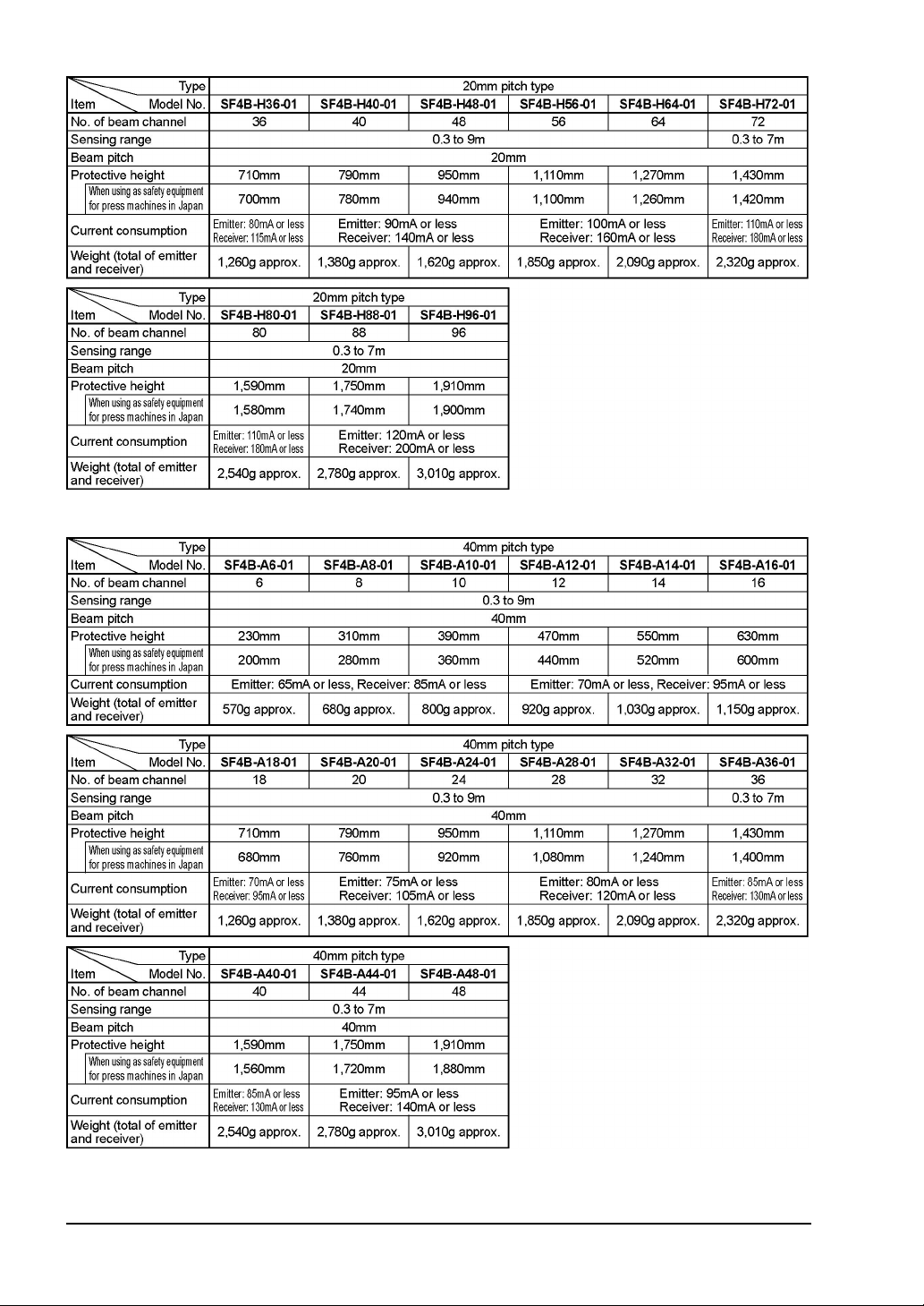
<40mm pitch type>
- 84 -
SUNX Limited MJE-SF4B01 No.0005-03V

Common specifications
Notes: 1) The beam channel is not turned OFF during muting even if it is blocked.
2) The cable can be extended within 30m (for emitter / receiver) when two sensors are connected with series
3) The intermediate supporting bracket (
connection, within 20m when three sensors are connected with series connection. Furthermore, when the
muting lamp is used, the cable can be extended within 40m (for emitter / receiver).
enclosed bracket differs depending on the sensor as follows:
SF4B-F -01
1 set :
SF4B-H -01
SF4B-A -01
2 sets :
SF4B-F127-01,SF4B-H -01
SF4B-A -01
3 sets :
SF4B-H -01
SF4B-A -01
㨯㨯㨯
Sensor with 79 to 111 beam channels
㨯㨯㨯
Sensor with 40 to 56 beam channels
㨯㨯㨯
Sensor with 20 to 28 beam channels
㨯㨯㨯
Sensor with 32 to 40 beam channels
㨯㨯㨯
Sensor with 88 to 96 beam channels
㨯㨯㨯
Sensor with 44 to 48 beam channels
MS-SFB-2
㨯㨯㨯
) is enclosed with the following sensors. The quantity of the
Sensor with 64 to 80 beam channels
<Reference>
Both emitter and receiver are adjusted before shipment, please apply both emitter and receiver with the same
serial No. The serial No. is indicated on the plates of both emitter and receiver. (The last 5 digits under the model
represents the serial No.)
SUNX Limited MJE-SF4B01 No.0005-03V
- 85 -

6-2
Options
Front protection cover: 1 pc.
Model No.
FC-SFBH-12 SF4B-F23-01, SF4B-H12-01, SF4B-A6-01
FC-SFBH-16 SF4B-F31-01, SF4B-H16-01, SF4B-A8-01
FC-SFBH-20 SF4B-F39-01, SF4B-H20-01, SF4B-A10-01
FC-SFBH-24 SF4B-F47-01, SF4B-H24-01, SF4B-A12-01
FC-SFBH-28 SF4B-F55-01, SF4B-H28-01, SF4B-A14-01
FC-SFBH-32 SF4B-F63-01, SF4B-H32-01, SF4B-A16-01
FC-SFBH-36 SF4B-F71-01, SF4B-H36-01, SF4B-A18-01
FC-SFBH-40 SF4B-F79-01, SF4B-H40-01, SF4B-A20-01
FC-SFBH-48 SF4B-F95-01, SF4B-H48-01, SF4B-A24-01
FC-SFBH-56 SF4B-F111-01, SF4B-H56-01, SF4B-A28-01
FC-SFBH-64 SF4B-F127-01, SF4B-H64-01, SF4B-A32-01
FC-SFBH-72 SF4B-H72-01, SF4B-A36-01
FC-SFBH-80 SF4B-H80-01, SF4B-A40-01
FC-SFBH-88 SF4B-H88-01, SF4B-A44-01
FC-SFBH-96 SF4B-H96-01, SF4B-A48-01
When the front protection cover is fitted, the sensing distance is shortened.
8-core bottom cap cable: 2 pcs./set
Applicable beam channel No.
When using this device as safety equipment for press machines, be sure to use the cable with
protective tube.
Protects the sensing surface of the sensor from
dirt, etc.
Remarks
[1 pc. for emitter (connector: gray), 1 pc. for receiver (connector: black)]
Type Model No. Cable length
Discrete
wire
Connector
SFB-CCB3
SFB-CCB7
SFB-CCB10
SFB-CCB15
SFB-CB05
SFB-CB5
SFB-CB10
10m
15m
0.5m
10m
3m
7m
5m
This cable is used for normal operation.
For emitter: 8-core shielded cable
For receiver: 8-core shielded cable
Remarks
12-core bottom cap cable: 2 pcs./set
[1 pc. for emitter (connector: gray), 1 pc. for receiver (connector: black)]
Type Model No. Cable length Remarks
Discrete
wire
Connector
SFB-CCB3-MU
SFB-CCB7-MU
SFB-CB05-MU
3m
7m
0.5m
This 12-core bottom cap cable is used when the muting function is
applied.
For emitter: 12-core shielded cable
For receiver: 12-core shielded cable
SUNX Limited MJE-SF4B01 No.0005-03V
- 86 -

8-core extension cable with connector on one end: 2 pcs./set
[1 pc. for emitter (connector: gray), 1 pc. for receiver (connector: black)]
Type Model No. Cable length Remarks
Discrete
wire
12-core extension cable with connector on one end: 2 pcs./set
SFB-CC3
SFB-CC10
3m
10m
This cable is used for extending the normal cable.
For emitter: 8-core shielded cable
For receiver: 8-core shielded cable
[1 pc. for emitter (connector: gray), 1 pc. for receiver (connector: black)]
Type Model No. Cable length Remarks
Discrete
wire
8-core extension cable with connectors on both ends: 1 pc.
SFB-CC3-MU
SFB-CC10-MU
3m
10m
In case of using the muting function, this cable is used for extending
the cable.
For emitter: 12-core shielded cable
For receiver: 12-core shielded cable
[1 pc. for emitter (connector: gray), 1 pc. for receiver (connector: black)]
Type Model No. Cable length Remarks
For
emitter
For
receiver
12-core extension cable with connectors on both ends: 1 pc.
SFB-CCJ10E
10m
SFB-CCJ10D
This cable is used for extending the normal cable.
The connector is attached on both ends of the cable.
For emitter: 8-core shielded cable
For receiver: 8-core shielded cable
[1 pc. for emitter (connector: gray), 1 pc. for receiver (connector: black)]
Type Model No. Cable length Remarks
For
emitter
For
receiver
Cable for series connection: 2 pcs./set
SFB-CCJ10E-MU
10m
SFB-CCJ10D-MU
In case of using the muting function, this cable is used for extending the cable.
The connector is attached on both ends of the cable.
For emitter: 12-core shielded cable
For receiver: 12-core shielded cable
(Common for emitter and receiver)
Model No. Cable length Remarks
SFB-CSL01
SFB-CSL05
SFB-CSL1
SFB-CSL5
0.1m
0.5m
1m
5m
Used to connect sensor in series.
Common for emitter and receiver.
SUNX Limited MJE-SF4B01 No.0005-03V
- 87 -

Compatible cable: 2 pcs./set
Type Model No. Cable length Remarks
Connector
SFB-CB05-A-P
SFB-CB05-A-N
SFB-CB05-B-P
SFB-CB05B-N
0.5m
This cable is compatible with, PNP output of
This cable is compatible with, NPN output of
This cable is compatible with, PNP output of
This cable is compatible with, NPN output of
SF4-AH
SF4-AH
SF2-EH
SF2-EH
[When this device is used as a safety equipment for press machines in Japan]
Cable with protective tube: Refer to the following table.
When this device is used as safety equipment for press machines, be sure to use the
cable with protective tube.
The protective tube is enclosed with the cable with protective tube.
series.
series.
series.
series.
Model No.
SFPB-CB05
SFPB-CB05-MU
SFPB-CB05-A-P
SFPB-CB05-A-N
SFPB-CB05-B-P
SFPB-CB05-B-N
SFPB-CSL05
SFPB-CB05EX
SFPB-CCJ1E
SFPB-CCJ1D
SFPB-CSL1
SFPB-CCB3
SFPB-CCB3-MU
SFPB-CC3-MU
SFPB-CB5
SFPB-CCJ5E
SFPB-CCJ5D
SFPB-CSL5
SFPB-CB5-EX
SFPB-CCB7
SFPB-CCB7-MU
SFPB-CB10
SFPB-CC10
SFPB-CCJ10E
SFPB-CCJ10D
SFPB-CCJ10E-MU
SFPB-CCJ10D-MU
SFPB-CB10EX
The length of the cable protective tube L
1
1.5
4
6
8
11
m
The number
enclosed
2 pcs.
2 pcs.
2 pcs.
2 pcs.
2 pcs.
2 pcs.
2 pcs.
2 pcs.
1 pc.
1 pc.
2 pcs.
2 pcs.
2 pcs.
2 pcs.
2 pcs.
1 pc.
1 pc.
2 pcs.
2 pcs.
2 pcs.
2 pcs.
2 pcs.
2 pcs.
1 pc.
1 pc.
1 pc.
1 pc.
2 pcs.
- 88 -
SUNX Limited MJE-SF4B01 No.0005-03V

Standard mounting bracket: 4 pcs./set M8 mounting bracket: 4 pcs./set
Model No.
MS-SFB-1
This mounting bracket enables easy
beam alignment.
For two hexagon-socket head bolts [M5].
Remarks
Model No.
MS-SFB-1-T
This mounting bracket enables easy
beam alignment.
For one hexagon-socket head bolt [M8].
Remarks
Pitch adapter bracket: 4 pcs./set M8 pitch adapter bracket : 4 pcs./set
Model No.
MS-SFB-4
Dead zoneless mounting bracket: 4 pcs./set
This mounting bracket is for replacing
the other SUNX light curtains (protective height 200mm or more) by
SF4B- -01
For two hexagon-socket head bolts [M5].
.
Remarks
Model No.
MS-SFB-4-T
This mounting bracket is for replacing
the other SUNX light curtains (protective height 200mm or more) by
SF4B- -01
For one hexagon-socket head bolt [M8].
.
Remarks
Model No.
MS-SFB-3
Laser alignment tool for light curtain: 1 pc.
Model No.
SF-LAT-2N
This is the mounting bracket for reducing the dead space.
Convenient for aligning the beam
channels.
Remarks
Remarks
SUNX Limited MJE-SF4B01 No.0005-03V
- 89 -

Connector connection type control unit: 1 pc.
y
Solid type control unit: 1 pc.
Model No.
SF-C11
This is the control unit conforming to
European / North American safety
standards and Japanese safety standards for press machine. Applicable to
8-core cable with connector.
Remarks
Model No.
SF-C12
This is the control unit conforming to
European / North American safety
standards (IP65). Applicable to
12-core cable with connector.
Remarks
Thin type control unit: 1 pc. Application expansion unit: 1 pc.
Model No.
SF-C13
This is the controller conforming to
European / North American safety
standards and Japanese safety standards for press machine.
Remarks
Model No.
SF-C14EX
(Note 1)
SF-C14EX01
(Note 2)
Notes: 1)
2)
SF-C14EX
safety applications in Japan.
SF-C14EX-01
with the handy-controller (
This controller conforming to European / North American safety standards and Japanese safety standards
for press machine. The muting control
function and the emergency stop
input etc., are incorporated, which
expand the applications of the light
curtain.
cannot be used for press machine
cannot be used in combination
Remarks
SFB-HC
) (optional).
[When this device is used as a safety equipment for press machines in Japan]
The control unit (
for ‘Model examination’ set forth in the Japanese Industrial Safety and Health Laws
Provision 44-2. When using this device in combination with
cannot be used as ‘safety equipment for press machines or shearing machine’, stated
in the Japanese Industrial Safety and Health Laws Provision 44.
SF-C12
) and the application expansion unit (
SF-C14EX
SF-C12
) are not tested
or
SF-C14EX
, the
SUNX Limited MJE-SF4B01 No.0005-03V
- 90 -

Test rod: 1 pc.
Protect bar set: 1 set
Model No. Remarks
SFB-TR24
SFB-TR34
SFB-TR45
Test rod for
Ǿ
24mm
Test rod for
Ǿ
34mm
Test rod for
It can be also used for
floating.
SF4B-F -01
SF4B-F -01
SF4B-A -01.Ǿ
type 1 beam channel floating.
type 2 beam channels floating.
45mm
SF4B-H -01
type 1 beam channel
Model No. Applicable model Remarks
MC-SFBH-12 SF4B-F23-01, SF4B-H12-01, SF4B-A6-01
MC-SFBH-16 SF4B-F31-01, SF4B-H16-01, SF4B-A8-01
MC-SFBH-20 SF4B-F39-01, SF4B-H20-01, SF4B-A10-01
MC-SFBH-24 SF4B-F47-01, SF4B-H24-01, SF4B-A12-01
MC-SFBH-28 SF4B-F55-01, SF4B-H28-01, SF4B-A14-01
MC-SFBH-32 SF4B-F63-01, SF4B-H32-01, SF4B-A16-01
MC-SFBH-36 SF4B-F71-01, SF4B-H36-01, SF4B-A18-01
MC-SFBH-40 SF4B-F79-01, SF4B-H40-01, SF4B-A20-01
MC-SFBH-48 SF4B-F95-01, SF4B-H48-01, SF4B-A24-01
MC-SFBH-56 SF4B-F111-01, SF4B-H56-01, SF4B-A28-01
MC-SFBH-64 SF4B-F127-01, SF4B-H64-01, SF4B-A32-01
MC-SFBH-72 SF4B-H72-01, SF4B-A36-01
MC-SFBH-80 SF4B-H80-01, SF4B-A40-01
MC-SFBH-88 SF4B-H88-01, SF4B-A44-01
MC-SFBH-96 SF4B-H96-01, SF4B-A48-01
Note: The protect bar intermediate supporting bracket (optional) is for the protect bar longer than
length. Use the bracket when the protect bar bends a lot.
This unit protects the lens surface of
the light curtain from being hit and
damaged by work pieces.
SUNX Limited MJE-SF4B01 No.0005-03V
MC-SFBH-48
in
- 91 -
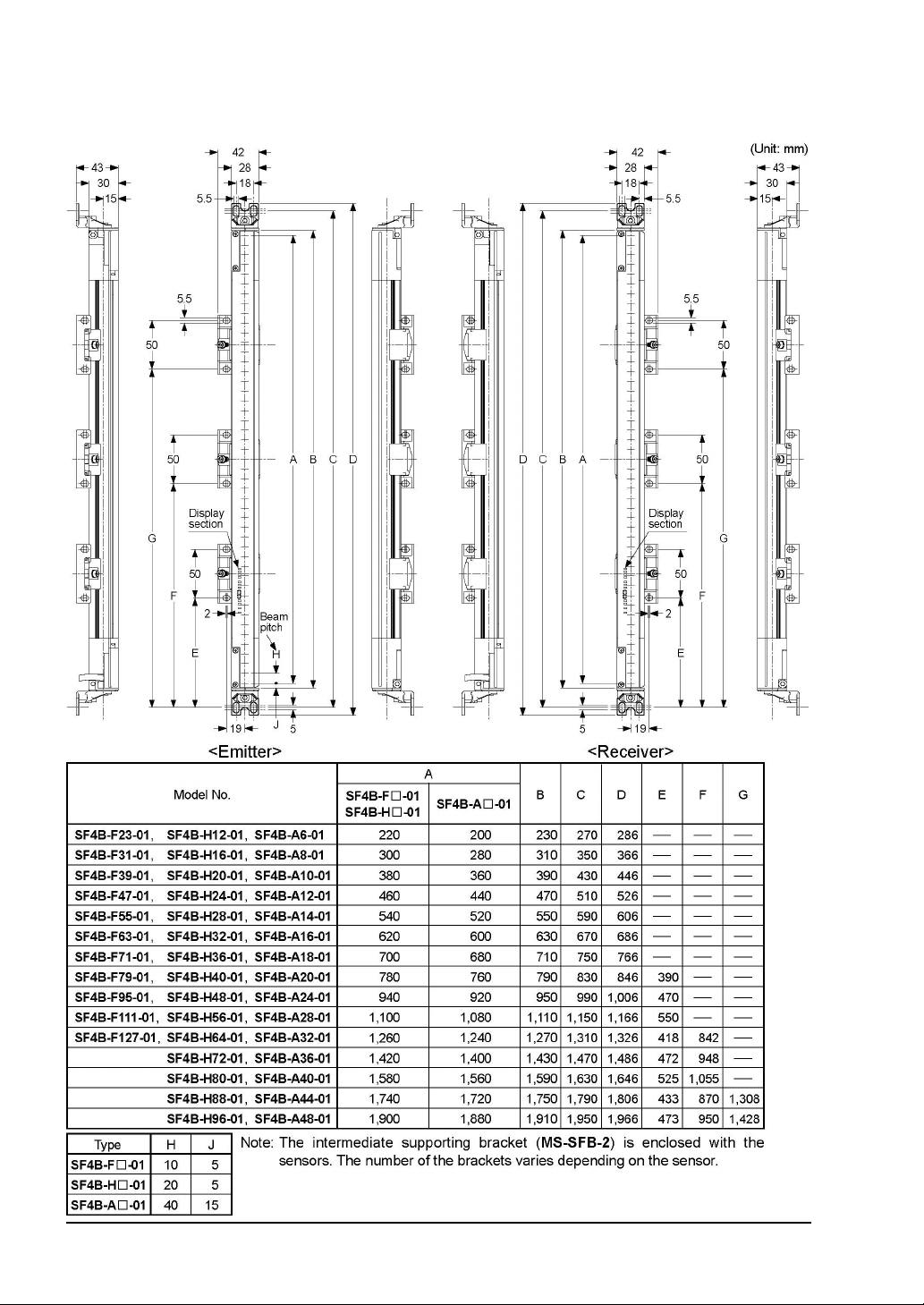
6-3
Dimensions
6-3-1 Rear Mounting with Standard Mounting Bracket (MS-SFB-1)
- 92 -
SUNX Limited MJE-SF4B01 No.0005-03V
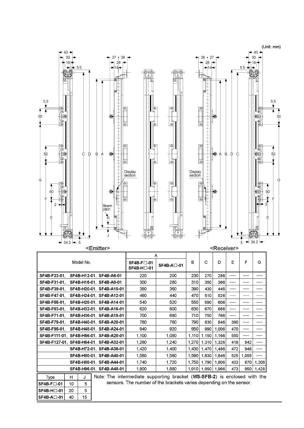
6-3-2 Side Mounting with Standard Mounting Bracket (MS-SFB-1)
SUNX Limited MJE-SF4B01 No.0005-03V
- 93 -

6-3-3 Rear Mounting with Dead Zoneless Mounting Bracket (MS-SFB-3)
- 94 -
SUNX Limited MJE-SF4B01 No.0005-03V
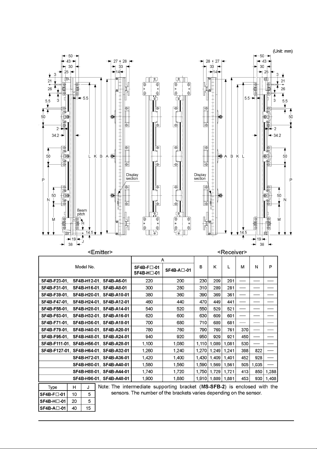
6-3-4 Side Mounting with Dead Zoneless Mounting Bracket (MS-SFB-3)
SUNX Limited MJE-SF4B01 No.0005-03V
- 95 -
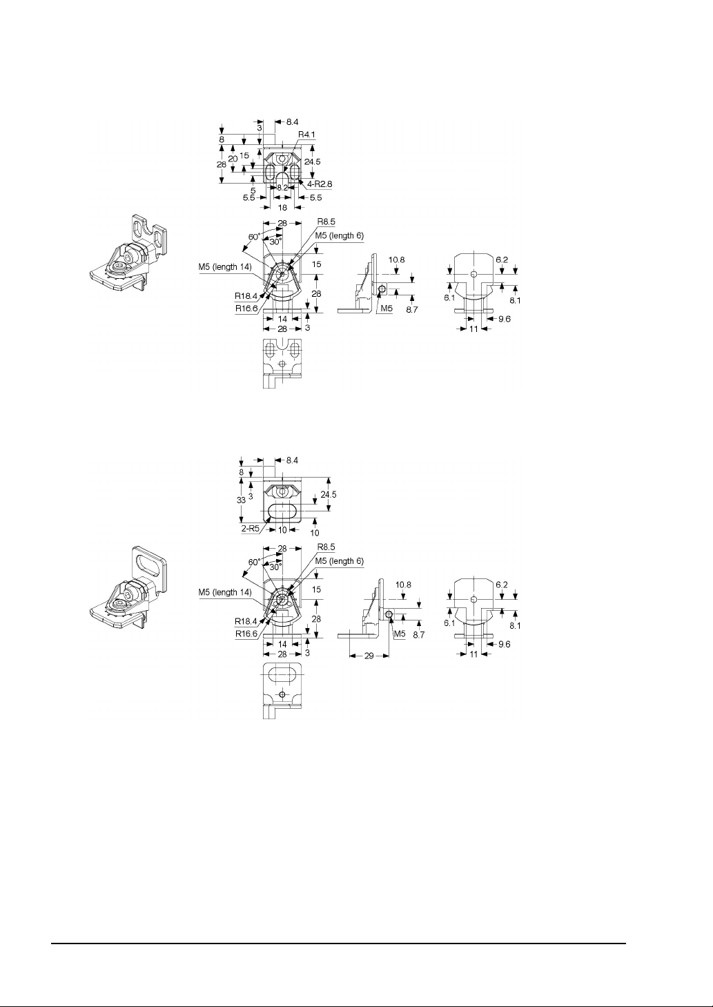
6-3-5 Mounting Brackets
1) Standard mounting bracket / MS-SFB-1
Material: ZDC2
(Unit: mm)
2 M8 Mounting bracket
Material: ZDC2
MS-SFB-1-T
- 96 -
SUNX Limited MJE-SF4B01 No.0005-03V

3Pitch adapter bracket / MS-SFB-4
Material: ZDC2
4M8 Pitch adapter bracket / MS-SFB-4-T
Material: ZDC2
SUNX Limited MJE-SF4B01 No.0005-03V
- 97 -

5Intermediate supporting bracket / MS-SFB-2
Material: ZDC2
6Dead zoneless mounting bracket / MS-SFB-3
Material: ZDC2
- 98 -
SUNX Limited MJE-SF4B01 No.0005-03V

Chapter 7 Others
7-1
Glossary
Machinery Directive This directive is for an assembly of linked parts or components, energized
by an electricity, compressed air or oil pressure etc. and at least one of
which moves, and a component which fulfills a safety function and is released into the market by itself.
EMC Directive The directives is to any electric or electronic devices which will create more
than a limited amount of RF interference, or will withstand a certain amount
of Electro Magnetic fields while operating as intended within specifications.
EN 61496-1
IEC 61496-1/2
UL61496-1/2
JIS B 9704-1/2
EN 55011 Specifies the limits and methods of measurement of radio disturbance
JIS B 9705-1
(ISO-13849-1)
UL1998 UL standard for safety-related software in programmable components.
Model Examination The standard for safety equipments structure of the Japanese Ministry of
ESPE The abbreviation for Electro-Sensitive Protective Equipment.
Output control
(OSSD)
FSD The abbreviation for Final Switching Device.
The standards that pertain to machine safety, especially electro-sensitive
protective equipment (ESPE).
EN 61496-1, IEC 61496-1, UL 61496-1 or JIS B 9704-1 gives general rules
or failure mode and effect analysis, EMC requirements, etc.
IEC 61496-2, UL 61496-2 or JIS B 9704-2 specifies effective aperture angle, protection against extraneous light sources, etc, for Active
Opto-electronic Protective Devices (AOPDs).
characteristics of industrial, scientific and medical (ISM) radio-frequency
equipment.
The standard that specifies the safety-related matters of machine safety /
control system.
Health, labor and Welfare.
The abbreviation for Output Signal Switching Device.
A component of the light curtain that turns off when light of the light curtain
is blocked.
The component of the machine’s safety related control system that
open-circuits the MPCE circuit when the OSSD operates due to the light
from the light curtain being blocked.
Test rod This is a rod for checking the detection capability of this device. It has di-
mensions corresponding to the minimum sensing object for this device.
Main side / Sub side For series connection, the side where the power supply or the output is
connected is called the main side, and the others are called the sub side.
Lockout It is one of the safe status of this device. Operation is stopped if the
self-diagnosis function determines that an irrecoverable failure (OSSDs do
not operate normally, etc.) has occurred. If an emitter is in lockout condition, it will stop emitting light. If a receiver is in lockout condition, OSSDs
are turned OFF.
Safety distance It is the minimum distance that must be maintained between the light cur-
tain and the dangerous parts of a machine so that the machine can be
stopped before a human body or an object can reach the dangerous parts.
SUNX Limited MJE-SF4B01 No.0005-03V
- 99 -

Protective height
(Sensing height)
The length of the beam axis direction that the min. sensing object can be
detected. The length from the center of the first beam channel to the center
of the last beam channel in addition to +10mm (+5mm upward, +5mm
downward). [However, if this device is used as safety equipment for press
machines in Japan, the protective height should be the from the center of
the first beam channel to the centre of the last beam channel.]
Sensing range It is the range between the facing emitter and receiver.
Sensing area It is the area over which intrusion by people or objects can be detected by
one set of sensor. It is given by the product of the protective height and the
operating range.
Emission halt function
This function enables checking of the receiver operation by turning off light
emission. It is possible to halt emission by keeping the terminal open, and
to have normal emission by connecting it to -V (+V for NPN output).
PSDI The abbreviation for the Presence Sensing Device Initiation.
The safety device that restarts automatically without any operation by the
operator after the device detects danger status and halts for a while.
- 100 -
SUNX Limited MJE-SF4B01 No.0005-03V
 Loading...