

Sunx SF1-N24, SF1-N16-H, SF1-N16, SF1-N24-H, SF1-N8 Instruction Manual
...
INSTRUCTION MANUAL
20mm Beam Pitch · General Purpose Area Sensor
SF1-N Series
Thank you very much for using SUNX products. Please read this
Instruction Manual carefully and thoroughly for the correct and optimum
use of this product. Kindly keep this manual in a convenient place for
quick reference.
If this product is used as a sensing device for personnel
protection, serious body injury or death could result.
Never use this product as a sensing device with any press
machine, shearing machine, roll grinding machine, forming
machine, vulcanizer, or robot etc. for protection of a hand or a
part of the body.
This product does not include a self-checking circuit for safety
functions necessary to allow its use as a sefety device. Thus,
a system failure or malfunction can result in either an
energized or a de-energized output condition.
When this product is used as a sensing device in the
following applications and if a problem relating to ‘law’ or
‘product liability’ occurs, SUNX shall not be liable for the
failure and for the damage or less.
Use of this product installed to a machinery or a device as
1)
a sensing device to detect a hand or a part of the
WARNING
operator’s body entering a dangerous area and stop the
machinery or the device.
Installation of this product to a protection device for
2)
preventing to enter a dangerous area and use of this as a
sensing device which detectes a hand or a part of the
operator’s body and open/close the door or window.
Use of this product as a sensing device for personnel
3)
protection (including interlock).
For sensing devices to be used as safety devices for press
machines or for personnel protection, use products which
meet standards, such as OSHA, ANSI or IEC etc., for
personnel protection applicable in each region or country.
In case of using as a safety device for press machine, use a
product approved by the Ministry of Labor in Japan.
1
SPECIFICATIONS
Number of beam channels
Model No.
Item
With spatter protection hood
Sensing height
SF1-N8
SF1-N8-H
140mm
Sensing range
Beam pitch
Sensing object
Supply voltage
Current consumption
Emitter: 55mA or less, Receiver: 60mA or less Emitter: 70mA or less, Receiver: 75mA or less Emitter: 85mA or less, Receiver: 90mA or less
Output
Output operation
Short-circuit protection
Response time
Emitter
Receiver
Indicators
Emitting indicator: Green LED
Operation indicator: Red LED (lights up when one or more beams are interrupted, and blinks when extraneous light is received)
Stable incident beam indicator: Green LED (lights up when all beams are received stably)
Unstable incident beam indicator: Yellow LED (lights up when one or more beams are received unstably)
The three color indicators blink in rotation when the receiving circuit fails, and blink simultaneously when the output circuit fails.
The operation indicator and the unstable incident beam indicator blink alternately when the emitting circuit fails or the synchronization wire breaks.
Test input function
Interference prevention function
Protection
Ambient temperature
Ambient humidity
Ambient illuminance
Emitting element
Material
Cable
Weight (total of the emitter and the receiver)
With spatter protection hood
500g approx.
630g approx.
Accessory
Notes: 1)
Output OFF condition
•
One or more beam are interrupted.
• Other components that the output transistor or the parts relevant to the output fail. (Note 2) • Some intense ambient light is received.
2)
The output transistor can be checked by the test cantrol function.
8
16
SF1-N16
SF1-N16-H
300mm
24
SF1-N24
SF1-N24-H
460mm
32
SF1-N32
SF1-N32-H
620mm
40
SF1-N40
SF1-N40-H
780mm
48
SF1-N48
SF1-N48-H
940mm
56
SF1-N56
SF1-N56-H
1,100mm
7m
20mm
ø30mm or more opaque object (ø35mm or more opaque object if the setting distance is 0.5m or less.)
12 to 24V DC±10% Ripple P-P 10% or less
Emitter: 100mA or less, Receiver: 105mA or less
NPN open-collector transistor
• Maximum sink current: 100mA
• Applied voltage: 30V DC or less (between output and 0V)
• Residual voltage: 1.6V or less (at 100mA sink current)
ON when all beams are received/OFF when one or more beams are interrupted (OFF, also, when the sensor fails.) (Note 1)
Incorporated
12ms or less
lights up under normal emission, blinks under emitting circuit failure or on cable break between the synchronization and the external input
terminals when interference prevention function is used (only the emitting indicator of the Sensor B blinks), and lights off under no emission
Incorporated
Incorporated
IP65 (IEC)
–10 to +55°C (No dew condensation or icing allowed), Storage: –10 to +60°C
35 to 85% RH, Storage: 35 to 85% RH
Sunlight: 20,000 x at the light-receiving face, Incandescent light: 3,500 x at the light-receiving face
Infrared LED (modulated)
Protection enclosure: Aluminum, Unit case: ABS, Front cover: Acrylic, Lens: Acrylic
840g approx.
1,080g approx.
2
4-core cabtyre cable, 0.5m long, with a round connector at the end
0.5mm
Use together with the optional mating cable
1,170g approx.
1,530g approx.
1,500g approx.
1,990g approx.
1,830g approx.
2,440g approx.
2,170g approx.
2,900g approx.
2,500g approx.
3,350g approx.
MS-SF1-1 (Sensor mounting bracket): 1 set
•
Either the emitting element, the emitting circuit, the receiving element, or the receiving circuit breaks.
•
Either +V wire, 0V wire, output wire, or synchronization wire breaks.
64
SF1-N64
SF1-N64-H
1,260mm
2,830g approx.
3,800g approx.
2
CAUTIONS
Make sure to carry out the wiring in the power supply off condition.
Take care that wrong wiring will damage the sensor.
Verify that the supply voltage variation is within the rating.
If power is supplied from a commercial switching regulator, ensure that
the frame ground (F.G.) terminal of the power supply is connected to an
actual ground.
Do not run the wires together with high-voltage lines or power lines or
put them in the same raceway. This can cause malfunction due to
induction.
Do not use during the initial transient time (1.5 sec.) after the power
supply is switched on.
Do not use the sensor without the front cover or the enclosure. IP
protection cannot be maintained and a contact failure may occur
between modular units.
Avoid dust, dirt, and steam.
Take care that the product does not come in direct contact with organic
solvents, such as, thinner, etc.
Take care that the sensor is not directly exposed to fluorescent light from a
rapid-starter lamp or a high frequency lighting device, as it may affect the
sensing performance
This sensor is suitable for indoor use only.
Extension up to total 20m is possible with 0.5mm2, or
.
Sensing
object
Emitter
Receiver
more, cable for both emitter and receiver.
Install the sensor where it cannot be affected by a
beam reflected from a machinery frame or a
workpiece. If the reflected beam is received, beam
interruption is not achieved.
The emitter and the receiver must face
each other corrctly. If they are set
upside down, the sensor does not work.
Cable
Make sure that stress is not applied
directly to the sensor cable joint.
When mounting the sensor, the tightening torque should be 2N·m or less.
Cable Cable
3
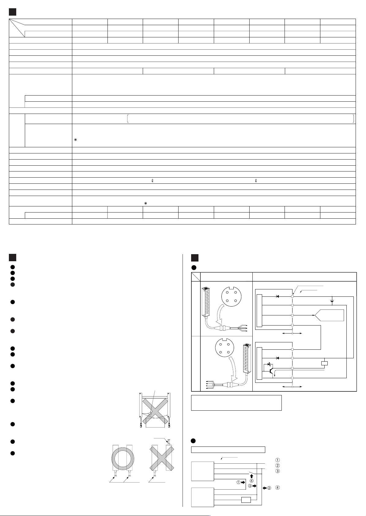
CONNECTIONS
I/O circuit diagram
Connector pin positions I/O circuit diagram
+VSync.
EmitterReceiver
Symbols···
Notes: 1)
21
34
+VSync.
Output
External
input
0V
21
34
0V
D
: Reverse supply polarity protection diode
Z
D
: Surge absorption zener diode
:
Tr
NPN output transister
Do not connect the synchronization wire to the ES terminal (external input) of
NPS or PS-930 sensor controller.
To supply power to the emitter and the receiver from separate power
2)
supplies, be sure to connect both 0V (blue) wires in common and adjust both
the power supplies to the same voltage.
Sensor circuitSensor circuit
Internal circuit
Z
D
Tr
Internal circuit
D
D
(Brown) +V
1
(Blue) 0V
3
(Pink) External input
4
(Orange/Violet)
Synchronization (Note 1)
2
(Orange/Violet)
Synchronization
(Note 1)
2
(Brown) +V
1
(Black) Output
4
(Blue) 0V
3
Wiring diagrams
When using one set of sensor
Emitter
Receiver
Color code
(Brown) +V
(Blue) 0V
(Pink) External input wire
(Orange/Violet) Synchronization wire
(Orange/Violet)
Synchronization wire
(Brown) +V
(Black) Output
(Blue) 0V
Load
Connect both the synchronization wires.
+V
Connect both the 0V wires in common.
0V
Although both the +V wires need not be
connected in common, they must be at
the same voltage.
To use the test input function, connect a
switch between the external input wire
and 0V. If this function is not used, insulate the external input wire.
Connector pin No.
Color code
Users' circuit
100mA max.
Users' circuit
+
12 to 24V DC
±10%
–
Used for test input
function or interference
prevention function.
Load
(Note 2)
 Loading...