

Page 1

Page 2
About the instruction manual (connection and operation) of the SD3-A1
and the SD3SOFT instruction manual (software operation)
The instruction manual (conn ection and operati on) for the SD3-A1 contains important
information on proper usage of laser scanner and usage in accordance with intend ed
purpose. F or additional inform ation on the configuration of the SD3-A1, please refer to
the SD3SOFT instructi on manual (software operation).
It is essential to observe all in formation in the instructi on manual (connecti on and
operation) and in the instruction m anual (softw are operation), especially the safety notes.
The instruction manual (connection and operation) and the instruction manual (software
operation) must be kept in a safe place. They must be available during the entire period
when the SD3-A1 i s in use. Documents ar e also aut omatically inst all ed on the PC wh en
SD3SOFT is installed and can be viewed at any time with the Help menu.
Safety and warning notices are identified by the symbol .
References to important information are identified by the symb ol .
References to the safety of laser devices are identified with the symbol .
SUNX Limited is not liable for damage caused by improper usage. The user must also be
familiar with all the SD3-A1 m anuals t o be able t o u se th e sy st em pr operl y.
Version: V5.5
Reprinting and duplic ation is prohibited in whole or in part without prior approval of
SUNX Limited.
2
Page 3

Contents
1 Approvals .........................................................................................................................................6
2 System Overview .............................................................................................................................9
3 Safety Notes and Usage in Accordance with Intended Purpose ............................................. 13
4 Applications for the SD3-A1 .........................................................................................................19
5 Information for Planning and Mounting...................................................................................... 25
1.1 Approval and declaration of EC conformity............................................................................6
1.2 Specialized technical terms and abbreviations ......................................................................7
1.3 Guidelines and standards ....................................................................................................... 8
2.1 Brief description and functional principle of the SD3- A1........................................................ 9
2.2 Special features of the SD3-A1............................................................................................ 11
3.1 General safety notes ............................................................................................................13
3.2 Usage requirements and usage in accordance with intended purpose ............................... 13
3.3 Restrictions for use ............................................................................................................... 14
3.4 Information related to detection zone cha ngeover ............................................................... 15
3.5 General information related to determining detection zone contours ..................................16
3.6 Additional safety notes for stationary use ............................................................................17
3.7 Additional safety notes for mobile use ................................................................................. 18
4.1 Stationary safeguarding of the danger area.........................................................................19
4.2 Access guarding by passage monitoring .............................................................................20
4.3 Safeguarding of danger points based on hand and arm protection.....................................21
4.4 Mobile safeguarding of automatic guided vehicles ..............................................................22
4.5 Protecting transporter trolleys against collisions .................................................................. 22
4.6 Guarding the sides on AGVs ................................................................................................ 23
4.7 Other possible applications ..................................................................................................24
5.1 Attachment and dimensions .................................................................................................26
5.2 Installing adjacent laser scanners ........................................................................................26
5.2.1 Constructive measures......................................................................................................... 26
5.2.2 Adjusting adjacent laser scanners........................................................................................ 27
5.3 Information on setting the dimensions of detection zones ...................................................28
5.3.1 Methods of configuring detection zones using the PC ......................................................... 28
5.3.2 Range of the detection zone, resolution ............................................................................... 28
5.3.3 Range of the warning zone, resolution.................................................................................29
5.3.4 Range of the measurement field ..........................................................................................30
5.3.5 Required detection zone additions Z....................................................................................30
5.4 Safeguarding stationary danger zones ................................................................................ 31
5.4.1 The purpose of safeguarding ............................................................................................... 31
5.4.2 Mounting position .................................................................................................................31
5.4.3 Mounting height ....................................................................................................................32
5.4.4 Recommendations for mounting to prevent unmonitored zon es .........................................32
5.4.5 Additions ...............................................................................................................................36
5.4.6 System availability ................................................................................................................36
5.4.7 Restart interlock....................................................................................................................37
5.4.8 Calculating the detection zone dimensions for safeguard ing an area .................................38
5.5 Access protection ................................................................................................................. 43
5.5.1 Object of protection .............................................................................................................. 43
5.5.2 Installation position ...............................................................................................................43
5.5.3 Safety-relevant settings, and calculation of the safety distance .......................................... 43
5.5.4 Definition of the reference bo undary ....................................................................................44
3
Page 4

5.6 Protecting danger points.......................................................................................................45
5.6.1 Object of protection .............................................................................................................. 45
5.6.2 Installation position ...............................................................................................................45
5.6.3 Safety-related settings, and calculation of the safety distance ............................................ 45
5.6.4 Defining the reference boundary ..........................................................................................47
5.7 Safeguarding mobile machines ............................................................................................ 48
5.7.1 The purpose of safeguarding ............................................................................................... 48
5.7.2 Installing adjacent laser scanners ........................................................................................48
5.7.3 Mounting position .................................................................................................................48
5.7.4 Mounting height ....................................................................................................................48
5.7.5 Recommendations for mounting to prevent unmonitored zon es .........................................49
5.7.6 Additions ...............................................................................................................................51
5.7.7 System availability ................................................................................................................52
5.7.8 Restart ..................................................................................................................................52
5.7.9 Calculating the dimensions of the detection zone of an AGV application ........................... 53
5.7.10 Side guarding configuration on AGVs ..................................................................................56
6 Details on Switching Over Detection and Warning Zones........................................................57
7 Functions of the SD3-A1............................................................................................................... 62
8 Integrating the SD3- A1 into Machine Controls ..........................................................................64
9 Electrical Connection....................................................................................................................69
10 Commissioning..............................................................................................................................73
6.1 Sequence of zone pair switchovers...................................................................................... 57
6.2 Practical AGV applicat ion (example) .................................................................................... 59
7.1 Restart ..................................................................................................................................62
7.2 Channels for zone pair changeovers, FP 1 to FP 4 .............................................................62
7.3 Alarm 1 (X1-5) ...................................................................................................................... 63
7.4 Alarm 2 (X1-15) .................................................................................................................... 63
7.5 OSSD 1 (X1-12) and OSSD 2 (X1-11) .................................................................................64
7.6 Data communication .............................................................................................................64
8.1 Integrating the SD3-A1 with external wiring with re lays and
eightfold zone pair changeover ............................................................................................65
8.2 Connecting the SD3-A1 to a safety sequence circuit with manual restart,
relay monitoring, without zone pair changeover .................................................................. 67
8.3 Connecting the SD3-A1 to a PLC with corresponding safety level
(Category 3 or higher, EN 954) and zone pair changeover .................................................68
9.1 Electrical power supply......................................................................................................... 69
9.2 Connecting the PC and control cables to the scanner ......................................................... 69
9.3 Connector assembly .............................................................................................................70
9.4 Points to consider when preparing and laying the cables .................................................... 70
9.5 Interface pin assignments.....................................................................................................71
10.1 Hardware and software requirements ..................................................................................73
10.2 Installing “SD3SOFT” and starting up the SD3-A1 ..............................................................73
10.3 SD3-A1 status indicator........................................................................................................ 75
10.4 Status information of the SD3- A1......................................................................................... 77
10.5 Restart and device swap-out ................................................................................................78
4
Page 5

11 Maintenance and Testing..............................................................................................................79
12 Delivery Package ...........................................................................................................................93
13 Technical Data ...............................................................................................................................96
14 Diagnostic Codes and Causes...................................................................................................103
11.1 Test before first startup by person qualified and authorized to perform the task ................ 79
11.2 Extended shutdown of the SD3- A1 ...................................................................................... 79
11.3 Regular tests by a person qualified and authorized to perform the task .............................80
11.4 Daily test by with test piece performed by responsible operating personnel ....................... 80
11.4.1 Checklist for daily test of stationary applications by responsible operating personnel ........81
11.4.2 Checklist for daily test of mobile applications by responsible operating personnel ............. 82
11.5 Checklist for testing stationary applications .........................................................................83
11.6 Checklist for testing mobile applications ..............................................................................85
11.7 Replacing the optical window ............................................................................................... 87
11.7.1 General information: .............................................................................................................87
11.7.2 Initial measurement of the new optical window.................................................................... 89
11.7.3 Procedure when using the SD3SOFT user software version 1.09 or later .......................... 90
11.8 Cleaning................................................................................................................................91
11.8.1 Cleaning the optical window when dirty ...............................................................................91
11.8.2 Cleaning the optical window; cleaning diffusing light panes ................................................ 92
12.1 Disposal ................................................................................................................................93
12.2 Accessories and spare parts ................................................................................................ 94
12.3 Coding of the control cable X1 .............................................................................................95
13.1 Test pieces ...........................................................................................................................96
13.2 Detection zone...................................................................................................................... 96
13.3 Detection zone additions ......................................................................................................97
13.4 Warning zone........................................................................................................................97
13.5 Contour measurement .......................................................................................................... 97
13.6 Electrical power supply......................................................................................................... 98
13.7 Inputs ....................................................................................................................................98
13.8 Outputs .................................................................................................................................98
13.9 Software................................................................................................................................99
13.10 Interfaces ..............................................................................................................................99
13.11 Optics....................................................................................................................................99
13.12 Environment and material................................................................................................... 100
13.13 Dimensional drawings of the SD3-A1 ................................................................................ 101
13.14 Dimensional drawings of the mount ing system.................................................................. 102
5
Page 6

1 Approvals
y
1.1 Approval and declaration of EC conformit
EC t yp e examin ation in accor d anc e with
DIN EN 61496 - 1 and IEC 6149 6 - 3
TUV
PRODUCT SERVICE GMBH IQSE
Ridlerstr. 65 80339 Munich
6
Page 7

1.2 Specialized technical terms and abbreviations
AGV Automatic Guided Vehicle (FTS in German)
AOPD Active Optoelectronic Protective Device
AOPDDR Active Optoelectronic Protective Device responsive to Diffuse
EDM External Devic e Monitoring
ESPE Electro-Sensitive Protecting Equipment (BWS in German)
N.O. N orm al open cont ac t
OSSD Output Signal Switching Device Safety-relevant switch output
PC Personal Computer
DZ Detecti on Zone (SF in German)
Reset Defined Reset or SD3-A1
RS-232 RS-232 interface
RS-422 RS-422 interface
ZP Zone Pair (contains 1 × detection zone and 1 × warning zone)
WZ Warning Zone (WF in German)
Table 1.2-1: Specialized technic al terms and abbreviations
Reflection
Monitoring of external control parts (relay monitoring)
(FP in German)
7
Page 8

1.3 Guidelines and standards
The following guidelines and standards are of critical importance for the implementation of laser
scanner. Guidelines providing particularly relevant information for users of such systems are
marked with an asterisk (
Guideline / Standard Designation
European Gu idelines
98 / 37 / EG Machine guideline
73 / 23 / EWG Low voltage guideline
89 / 336 / EW G EMC guideline
A Standards
ISO 12100-1 and 2 Safety of machi nery - basic concepts
ISO 14121 Safety of machi nery - principles for risk assessment
B1 Standards
ISO 13852 Safety of m achinery - safety di stances to prevent danger
ISO 13849-1 Safety of machi nery - Safety related parts of control
ISO 13855 Safety of machinery. The positioning of protective
B2 Standards
IEC 60204-1 Safety of m achinery - Electric al equipm ent of machines -
IEC 60825-1 Safety of laser products - Part 1: Equipm ent classification
IEC 61496-1 Safety of machinery. Electro-sensitive prot ective
IEC 61496-3 Safety of machinery - Electro-sensitive prot ective
C Standards
DIN EN 775 Industrial robots - Safety
DIN EN 1525 Safety of industrial trucks - Driverless trucks and their
DIN EN 12895 Industrial trucks - El ectromagnetic compatibility
*
).
zones being reached by the upper limbs
systems; Part 1: General principl es for design
equipment in respect of approach speeds of parts of the
human body
Part 1: General requirem ents
and requirements
equipment. General requirements and tests
equipment - Part 3: P articular requir ements for Active
Opto-electronic Protective Devices responsive to Diffuse
Reflection (AOP DD R)
systems
*
*
*
*
*
*
*
8
Page 9

w
t
Guideline / Standard Designation
National Standards
DIN 15185-2 Warehousesyst ems with powered industrials trucks
Table 1.3-1: Guidelines and standards
This list does not claim to b e complete. In certain cases, the concrete requirements of the
application will necessitate the application of additional guidelines and standards!
*
2
System Overvie
2.1 Brief description and functional principle of the SD3-A1
The SD3-A1 is an optical distance sensor th at takes two-dimensional m easurements. I
could also be referred to as an optical area radar device. The sensor uses a rotating
deflecting unit to periodically emit light pulses within a working range of 190°.
If these pulses strike a person or an object, the reflected light is received and evaluated
by the SD3-A1. The sc anner calculates the precise coordinates of the person or object
bas ed on the t ravel time of the refl ected light and the c urrent an gl e of th e defl ecting unit.
If the person or object is within the bounds of a previously defined area called a detection
zone, a safety-oriented switching function is performed. This switching function causes
the semiconductor outputs to be switched OFF. The safety-oriented switching function
cannot be reset until the detection zone is clear. Depending on the operating mode, the
reset can be initiated eith er automatically or manually.
9
Page 10
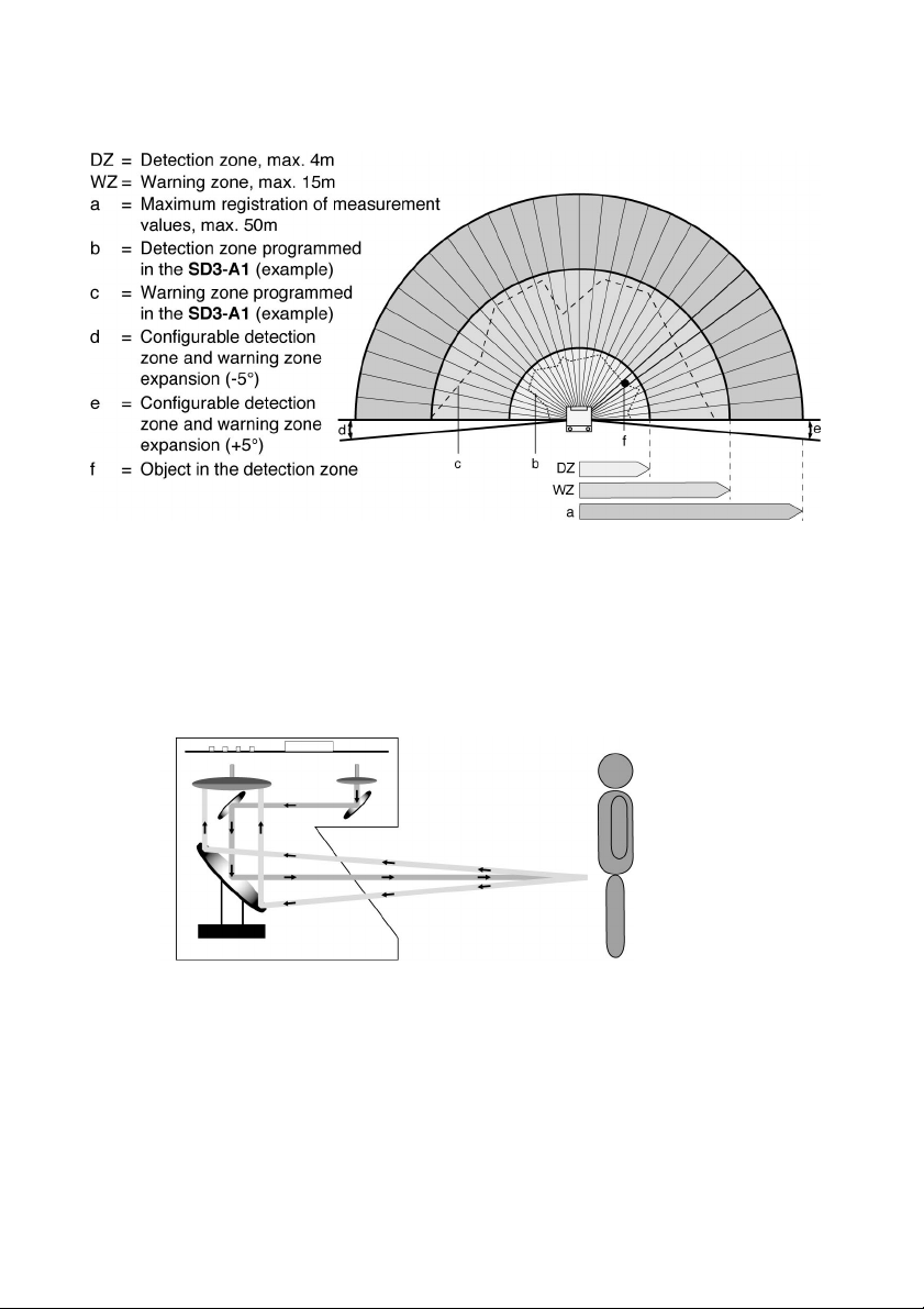
Fig. 2.1-1: The 190° angle range of the SD3-A1 is divided into 0.36° angle
A laser diode coupled with transmitter optics produces focused li ght pulses. These pulses
are projec t ed acr oss the m oni tored su rf ac e by a rot at in g m irror in suc h a way t hat a light
pulse is triggered in each of the angle segments within 40ms (scanning rate: 25 scans/s).
segments.
10
Fig. 2.1-2: Functional principle of the SD3-
The SD3-A1 can detect peopl e up to a distanc e of 4.0m even if they are wearing very
dark clothing or exhibit a low degree of reflectance. Dangerous movements are brought to
a standstill by two failsafe semiconductor outputs.
A1
Page 11

Objects (min. 150 × 150mm) are detect ed up to a di stance of 15m (c orresponds to the
r
r
warning zone) and signaled by way of a non-safety-related semiconductor output.
Eight programmable zone pairs (each of which consists of one detection zone and one
warning zone) enable the scanner to be optim ally adapted to the needs of each particula
application.
The SD3-A1 c an b e i mplem ented n ot onl y on m achin es and system s ( st ation ar y
safeguarding of danger zones), but also on vehicles (mobile safeguard ing of transport
vehicles).
Due to its wide rang e of measurem ent and its non-c ontact, electro-sensitive
measurem en t p ri nciple, th e SD3-A1 can be effectively used as a protective device fo
virtually any application.
2.2 Special features of the SD3-A1
x Eight freely programm able detecti on zones (up to a maximum of 4m)
x Eight freely programm able warning zones (up to a maximum of 15m)
x Expanded monitoring rang e of up to 190°
x ConfigPlug for easy device exchange without configuration expense
x Compact design (W × D × H: 140mm × 135mm × 155mm)
x Light weight (2kg)
x Low power consumption requirements (300mA, plus the load at the output s)
x Two types of int erfaces at one Sub-D jack (RS-232 and RS-422)
x User-friendly softw are
11
Page 12
12
Page 13

3 Safety Notes and Usage in Accordance with Intended Purpose
r
A
3.1
3.2
General safety notes
The protective functi on of the d evi c es c an be n egati vely affected, how ever, i f they are
used improperly or not in accordance with their intended purposes. If this occurs, it may
not be possibly to safeguard danger areas completely or at all, which may result in
danger to life and / or limb for persons who are in the general area of the machines or
systems.
Caution – laser radiation!
The SD3-A1 is a laser device belonging to laser class 1. The valid legal and local
regulations for operating laser syst ems must be compli ed with.
Avoid p ositioning t he sc anner at ey e l evel.
Usage
The relevant regulations for machine safety apply for the use of the laser scanner
SD3-A1. Responsible authoriti es (for example professional trade unions, OSHA) are also
avai labl e for qu est ions rel at ed to safet y. In gen er al, the following u sage requirem ents
must be observed:
x If the scanner is enclosed in a protective housing, additional window material, such
x Avoid touching the scanner optical window and the six diffusing light screens.
x The SD3-A1 is not suit abl e for use as a prot ec ti ve d evic e:
x The SD3-A1 corresponds to Type 3 in accordanc e with IEC 61496 -1 and 3.
x The elec tr ic al connection of the SD3-A1 to the control system must only b e made by
x The 24V DC (+2 0% / -30% ) power supply must be ensur ed by a safe network
equirements and usage in accordance with intended purpose
as plastic or gl ass must not be used as it may impair th e detection.
- if it is possible that dangerous fluids will be spewed out or objects will be ejected.
- for machines with long braking tim es (max. depth of the detection zone: 4m)
safety
cat egory of 3 in accord anc e w it h EN 954-1 c an b e ac hi ev ed with the SD3-A1 if all
other elements in th e safet y chain are set up to stop th e d angerou s m otion in
accordance with that safety category.
an electrician.
disconnect in accordance with IEC 742. The sam e requirements apply to all
connected input and output circuits.
13
Page 14

x The 24V DC pow er m ust be supplied to th e scanner t hr ou gh a se pa rat e branc h w it h
a 1.25A delayed action fuse in the control cabinet.
x You must ensure that prot ec ti ve caps ar e scr ew ed ont o i nt er fac es X1 and X 2. This
will protect the interfaces against dust.
x The safety output has a double design. The two OSSDs must always be included in
the shut-off circ ui t of t he mac hi ne in such a mann er th at eit he r o f t he t w o is
completely sufficient by itself t o turn OFF the m otion that presents a dang er.
x The alarm output 1 (Pin 5 on X1) must not be used to switch safety-related sign als.
x System tests (of the scanner, m achine, control c omponents and switch com ponents)
may only be performed when they do not result in potential hazards for people.
x Tampering with or making changes to the SD3-A1 can result in the loss of the safety
function.
x Only expert tr ained personnel is allowed to perform startup, maintenance, parameter
settings or detection zone configurations. Familiarity with the safety notes in this
instruction manual (c onnecti on and operation) and in the instruction manual
(so ftware operation) for th e “SD3SOFT” program constitutes part of this expert
know l edge.
x The password required for configuring safety-relevant param eters must be kept in a
secure location by the safety official. Information about password levels can be
found in the instruction manual (software operation) for the “SD3SOFT”.
x If the machine is designed for start interlock / manual restart, all detection zones
must be checked before enable - no one is permitted in the danger area.
3.3 Restrictions for use
x Glass, highly reflective materials such as mirrors (reflectance > 10.000%), or objects
that do not reflect any li ght back to the sensor can falsi fy the measurement result.
More inform ation is available in Chapter 5.3.5.
x Do not expose the SD3-A1 to flying sparks (for example a welding flash). Doing so
may caus e damage t o t he optical wind ow.
x Vap or, sm ok e, dust and all parti cles visible i n t he air have a signi ficant neg ativ e
effect on measurement values and will result in the semiconductor outputs being
turned OFF.
x Avoid ext rem e variat ions in tem p eratu re.
14
Page 15

r
r
x Make sure that the following types of light sources are not present on the sc anning
plane:
Laser light from o ne or m or e ot h er scanners or sens ors
Infrared light
Fluorescent light
Stroboscopic light
Please consid er as well Chapter 5.2.
x It must not be used for vehicles with int ernal combustion engines.
x The SD3-A1 is conc eived for u se i nside enc losed spac es and w it h the op er ati ng
parameters listed in the technical specifications (temperature, humidity, shock,
vibration, etc.). Please refer t o the list of parameters in Chapter 13.
x Avoid having reflective surfaces (such as glass, mirrors, retro-reflect ors, etc.) at fixed
contours in the scanning plane. If this is not possible, an additional detection zone
must be provided.
3.4 Information
If alternating operation is included in the design, and thus detecti on zone changeover, the
activation and effect of the detection zone in question must match the alternating
operating mode.
x The new detection zone must be activated before turning OFF the previous
detection zone. The time at which the changeover is made must be based on a ri sk
analysi s.
x Braking paths, response and coast -down tim es must b e taken int o consideration
(for example overlapping detection zones).
x A “Start interlock” function is provided.
x If the machine has a restart key, it must not be possible to operate it from inside the
det ection z ones. Al l dang er areas m ust b e visible from the p osit ion of the but t on.
Before releasing the start / restart interlock, all detection zones must be tested. No
one is permitted inside the danger areas.
x There m ust b e no unmonitor ed zones in si de the dang er ar eas.
x There must be no possibility for direct access to the danger area that shortens the
necessary safety distance (use a protective grid, for example).
x The information on required detection zone additions in Chapter 5 m ust be
observed.
elated to detection zonechangeove
15
Page 16

3.5 General information
r
r
A
x Shadow effects (e.g. surfaces or areas located behind stationary objects) must be
considered. As a rule, insufficient safeguarding must be adequately sup plemented
by further safety measures such as protective grid, light curtains, and the like!
x Access to the detection zone in the dangerous area is not permitted.
x When setting the dimensions of the detection zone, you must comply with the
formulas cited in Chapters 5.4.8 and 5.7.9! Be sure to comply with higher-level
machine standards (e.g. DIN EN 1525) if applicable.
These c ontai n indivi dual speci ficati ons, for exam ple, on point s of access t o the
danger zone and, if applicable, detection zone additi ons that must be given special
considerati on.
They al so pr ovide info rm ati on on how t o measur e safe ty dist anc es at machi nes.
x Det ecti on z on es w ith a r adi us sm aller than 20c m (at or c lose t o t he scann er) ar e not
admissible. 20cm is the preset minimum contour.
x When setting the dimensions of the detection zones, please comply with the
maxim um angle rang e st at ed in t he technic al sp ecificati ons (Chapt er 1 3.11).
x Needle-shaped detecti on zone contours are not p ermitted, since they do not ensure
any protective effect. For additional information, please refer to the SD3SOFT use
software (Chapter entitled “Definition of detection zones”).
x Due to possible measurement errors, every detection zone has an additions area in
which detection is not guaranteed under all conditions. Please c onsider as well
Chapter 5.3.5. Read Chapt er 5.4.6 and 5.7.7 for information on optimizing system
availability.
x The required safety distances must be taken into account when m aking detection
zone configurations. Safety distances are calculated according to formulas found in
either the machine-specific C standards or the general B standards IEC 61496-3 in
combinati on with DIN EN 999 (see Section 2 and 5 of the standard). T olerance fields
and / or additi ons (make sure to consid er Chapter 5.4 and 5.7).
x
fter the detection zones have been set, make a printout of the following
informati on:
Detection zone contour with the X and Y coordinates
Date
Serial num b er of the sc ann er
Name of the safety official
x When calcul ati ng the ad diti ons, be su re t o c onsider wh ether th e du st alg ori th m is
deactivated or activated (see Chapt er 5.3.5).
elated to determining detection zone contours
16
Page 17

x When calculating the safety distanc es, be sure to consider all delay times, such as
o
r
y
y
r
o
the r es pons e tim e of th e sc anner, r esponse time of t he contr ol elem ents, and
braking times and / or stopping times of the machine / system or AGV! Variations in
delay time caused by fact ors such as reduced braking power must also be taken int
considerati on.
x The effectiveness of the switch-off function must be tested along the defined contou
of the detecti on zone during th e initial startup and subsequent to any changes made
to a machin e or syst em .
x The effectiveness of the switch-off function must be tested for the detection zone
contours along the entire driving route during the initial startup and following an
changes made to an AGV.
x In the event that there is insufficient room available to allow the full dimensions of a
detection zone, for example because of the position of the scanner, additional safet
measures (e.g. protective grids) must be installed.
x Following each definition of and change t o the detection zones, the configuration
must be checked to see whether the possibility of people standing in the dange
zone as well as any barriers provided have been considered by an appropriate
layout of the detection zone(s).
3.6 Additional safety notes for stationary use
x If the danger zone can be accessed from the side, and if the detecti on zone cannot
be extended sufficiently in this direction, additional safety measures (e.g. protective
grids) m ust be inst alled.
x We recommended marking th e contour of the detection zone on the floor by painting
a colored lin e or applying c olored adhesive tape.
x Check the mounting regul arly (in particular, the angle of inclination) in order t
guarantee the reliability of detection.
17
Page 18

3.7 Additional safety notes for mobile use
f
x There are additional requirements for the use of scanners on automatic guided
vehicles (AGV) and transporter trolleys according to DIN EN 1525.
x If possible, expanded detection zones to each side should be provided in order to
safeguard access from the side and dir ectly in front of the vehicle.
x If is it not possible to completely safeguard the contour of th e vehicle including its
trailer and the dimensions of its load while making curves, additional protective
devices such as switch strips must be att ached to the side of the vehicle.
x There m ust b e a m in imum safety dist anc e S
on both sides. A one-sided minimum safety distance is admissible in certain
exception al cases. Th e specifications of DIN EN 1525 must be complied with.
x The basic value of the detecti on zone width for an AGV corresponds t o the
maximum vehicle width including the trailer and the dimensions of the load plus the
detection zone additions Z
AGV while making curves must be considered when defining detection zones.
x If the SD3-A1 is mounted on vehicles, the mounting (especially the angle o
inclination), the vehicles' braking p ower, and if applicable, play in the vehicle
guidance (the difference betw een the optimum and actual line of guidance) must be
regularly checked in order to guarantee the reliability of detection.
. Furtherm ore, the greatest possible lateral shift of the
S
of 500mm to the side of the vehicle
AB
18
Page 19
4 Applications for the SD3-A1
f
Due to its continuous c overag e of the area, its wide r ange, and the ability to select among
eight zone pairs, the SD3-A1 is able to handl e even complex applications.
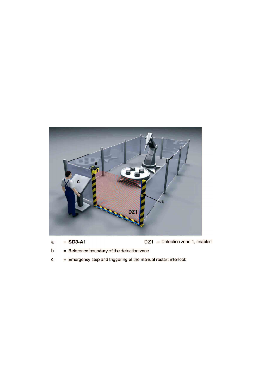
4.1 Stationary safeguarding of the danger area
The SD3-A1 is used to safeguard dangerous working areas at machines and systems
where bot h c on st ant an d v ariabl e dem ands are pl ac ed on t he geom etrical sh ap e of the
detection zone. The aim is to prevent people from entering the danger zone or reaching
the danger point with their upper and / or lower extr emities, at the same time without
impeding th e production process.
The SD3-A1 can b e m ounted di rectly at t he m achin e t abl e or on the sid e o r in fr ont of t he
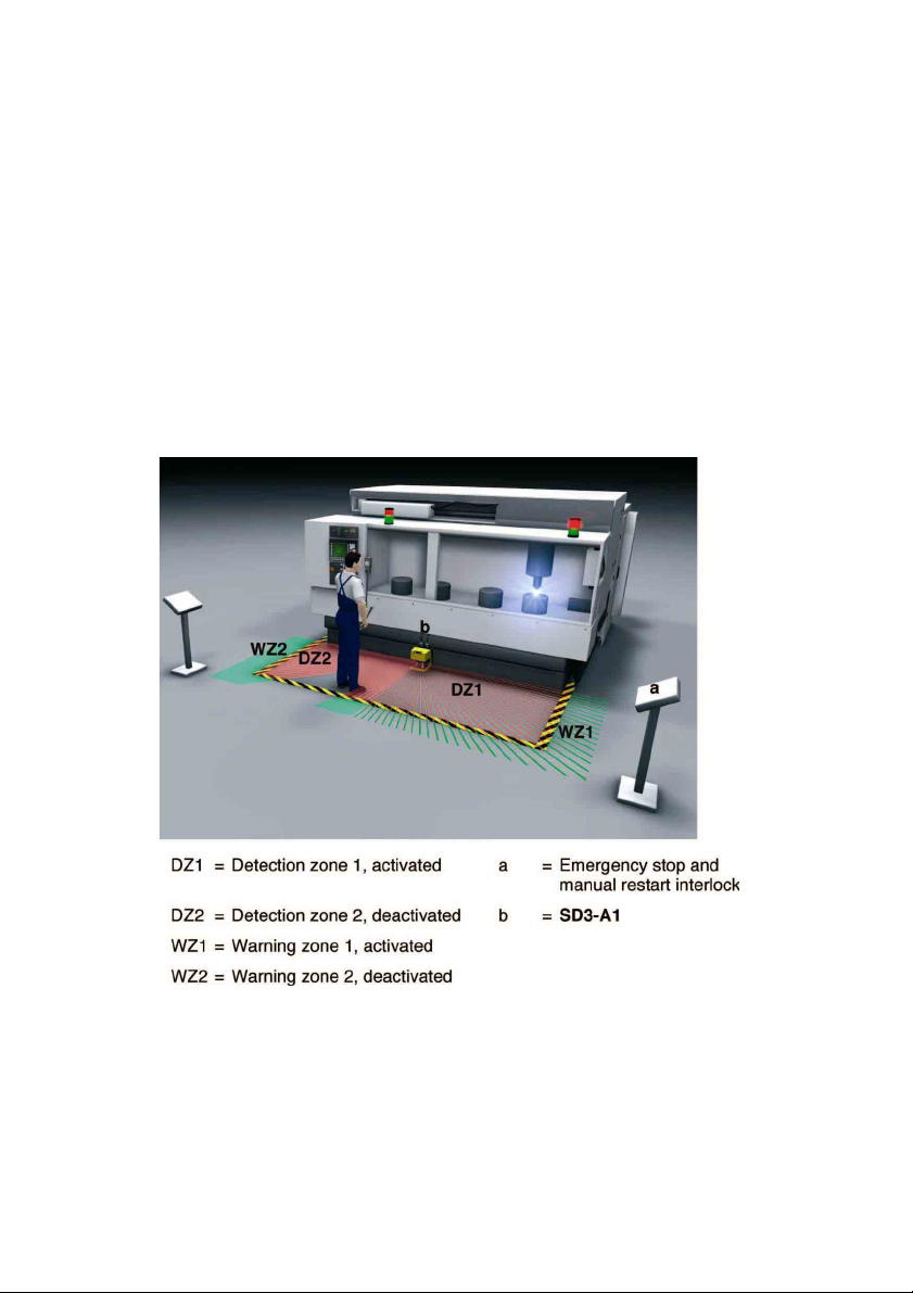
machine.
Fig. 4.1-1: Danger area guarding at st ationary machinery with two alternating work
Please comply with the safety notes in Chapt er 3 and Ch apter 5.4.7. For an example o
how to calcul ate detection zone measures, pl ease refer t o Chapter 5.4.8.
areas
19
Page 20
4.2 Access guarding by passage monitoring
o
Access guarding by passage monitoring (whole body trip control) is a suit able method
when the access to a machine or to a hazardous zone can be precisely defined in
structural terms, and there is no other unprotect ed access to the area. It is best to mount
the l aser sc anner ab ov e the p as sag e i n questi on, in vertic al ali gnment. In order to sec ure
the protecti ve equipm ent, laser scanner and fenc e against inadvertent misadjustm ent and
manipulation, the detection zon es of the SD3-A1 must be defined on the basis of a
reference boundary. In this operating mode, the scanner will use the polled environment
as a r ef er ence and so ch ec k for c hang es in t he lay out of th e prot ec ti ve eq uipm ent, as w ell
as checking every one of the individual measur ements it carries out with a view t
detecting an intrusion. An exam ple of the configuration of the SD3-A1 to give access
protection by passage monitoring will be found in Chapter 5.5.
20
Fig. 4.2-1:
Access guarding by whole body trip control with system check of a
reference boundary
Page 21
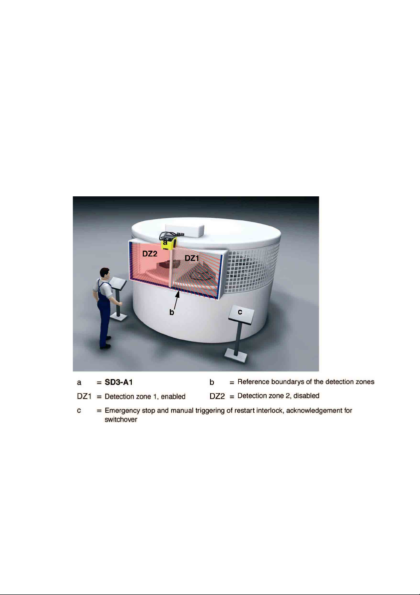
4.3 Safeguarding of danger points based on hand and arm protection
r
If the machine operator, in close proximity to the danger zone, needs to halt the
hazardous m ovement of the machi ne or t o coordinate the handling of workpieces or thei
rem ov al from t he machi ne, the m achine m ust b e provid ed wi th protect ion at the d an ger
point. To safeguard danger points in this way a protective syst em needs to be installed.
The SD3-A1 is certified as a system providing hand and arm protection, and is able in
such a situation to guarantee flexible safety conditions in the workplace. This may be
com bined wi th alt er nat i on of the d et ecti on z on es. In ord er to safeguar d t he prot ecti ve
equipment, laser scanner and side-mounted panels (which serve as a reference and
provide additional access protection) against inadvertent misadjustment or manipulati on,
the detection zones of the SD3-A1 must be de fi ne d on th e basi s of a refer ence bound ar y.
An exam pl e of th e c onfigur ation of th e SD3-A1 for the protecti on of danger p oints based
on hand and arm protecti on may be found in Chapter 5.6.
Fig. 4.3-1: Safeguarding of danger p oints based on hand and arm protection with
alternation of detection zones
21
Page 22
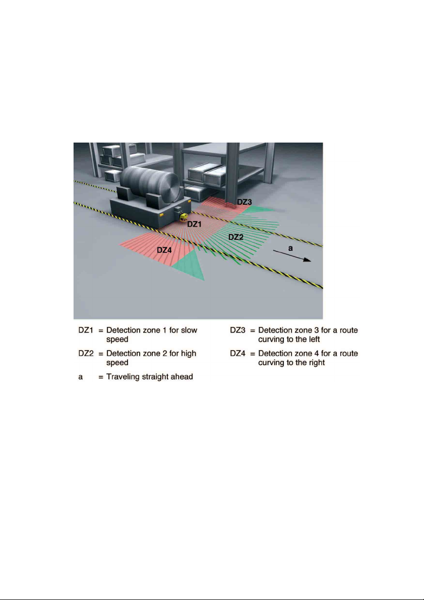
4.4 Mobile safeguarding of automatic guided vehicles
f
For this application, the SD3-A1 is installed on automatic guided vehicles in order to
monitor the vehicle path. The aim is t o detect people or objects in the path of the vehicle
and to automatically bring the vehicle to a halt. Safety systems available up to now, such
as bumpers or safety bars, have allowed only very low driving speeds t o be maintained.
In contrast, using the SD3-A1 as a n on-c ont ac t “ advanc e bump er ” results in the cr eat ion
of a substantially larger safety zone.
The vehic l es c an m ove fast er, an d d own tim es are reduced to th e necessary minimum.
Fig. 4.4-1: Safeguarding an automatic guided vehicle
Please comply with th e safety n otes in Chapter 3. For an exampl e of how to calculate
detection zone measures, please refer to Chapter 5.7.9.
4.5 Protecting transporter trolleys against collisions
Transport er trolleys are generally guided along a system of rails or grooves in the fl oor.
Hence the vehicle paths are usually just slightly wider than the trolleys themselves. This
represents an increased hazard for peopl e, since it is impossible to get out of the way o
the t roll ey. For this re ason, tr anspo rt er t roll ey are u sed in encl osed areas equipped with
suitable access safeguarding.
22
Page 23
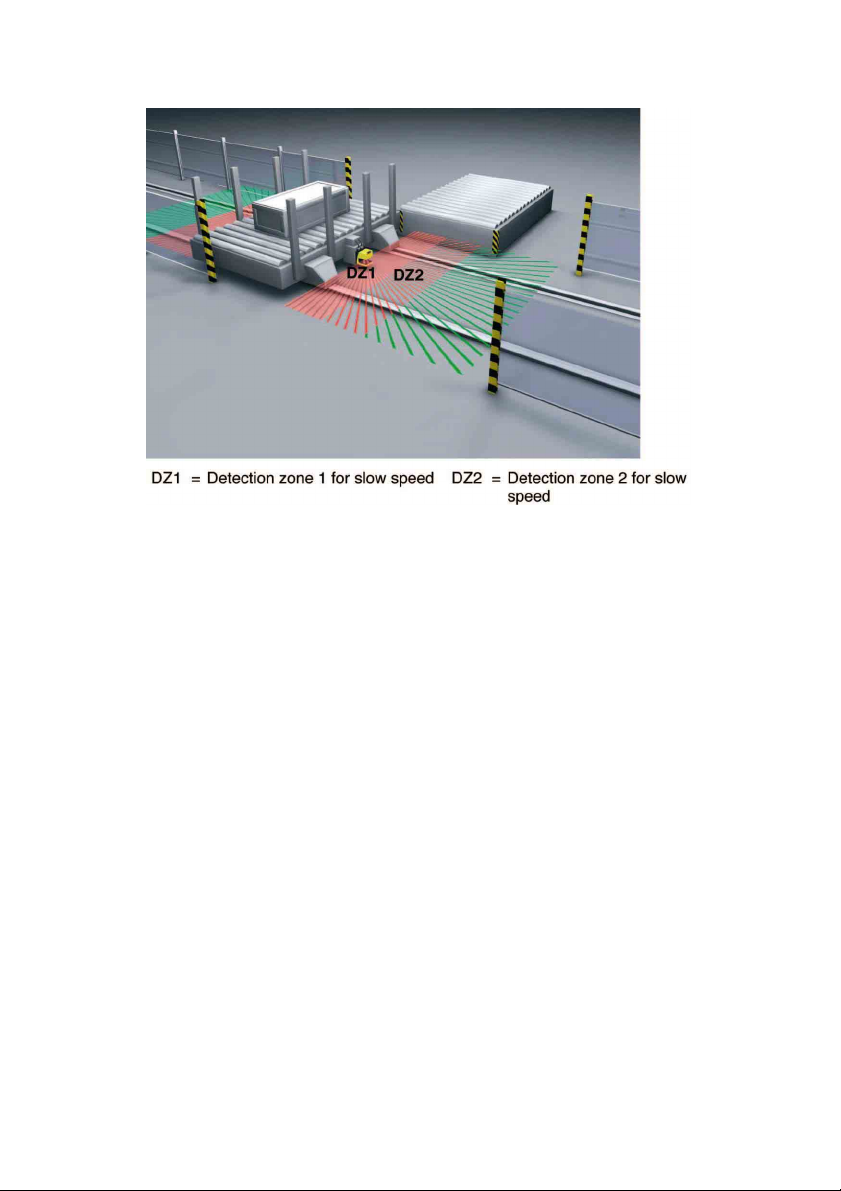
Fig. 4.5-1: Safeguarding a transport er trolley
y
Please comply with the safety notes in Chapter 3 and Chapt er 5.7.8.
In these cases, the SD3-A1 is used to detect people or objects in the vehicle path and
then automatically bring the vehicle to a halt. Select “Manual restart” mode.
The demands placed on the geometric al shape of the detecti on zone are determ ined b
the vehicl e width, speed, stopping distance and response time. Here as well, factors such
as ad dition s in the di rect ion of travel for t ol erances in th e m easurement v alu e and
reduced braki ng power du e to wear and tear must be taken into consideration.
4.6 Guarding the sides on AGVs
In addition to the danger area guarding of the path of an AGV application, in some
cases it is also necessary to set up a side guarding. This side guarding detects people
in the space between vehicle and conveyor, or detects people that stand on the
conveyor edge in the vehicle area. Furthermore, the side guarding also enables the
correct position of the load to be m onitored, so that a transport with overhanging load is
not initiated.
23
Page 24
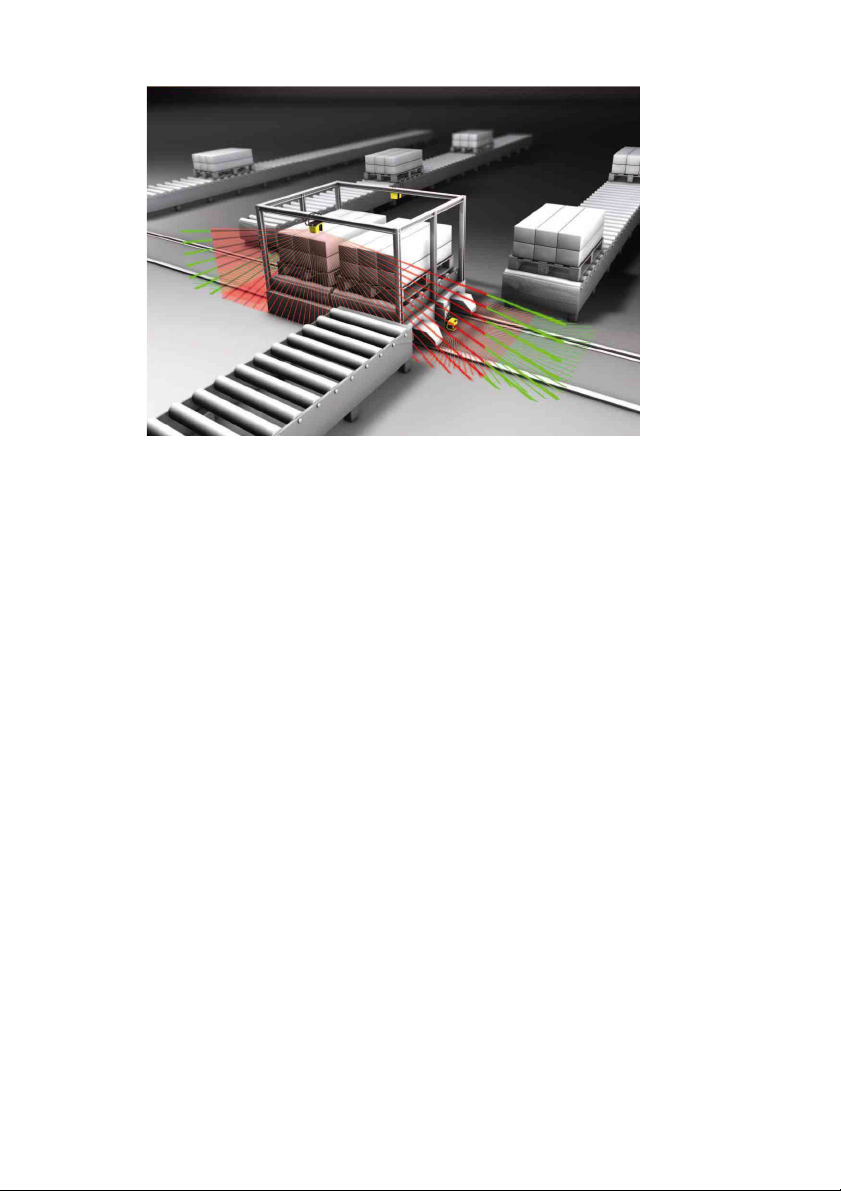
Fig. 4.6-1: Bild 6.3-1 guarding the sides on AGVs
Please observe the safety notes in Chapter 3. An example for the side guarding
configurati on on AGVs can be found in Chapter 5.7.9 and 5.7.10.
4.7 Other possible applications
x Object and contour measurement
x Logistics (counting, measuring, controlling)
x Projec tion control (e.g. in fully autom ati c parking ramps or l ots)
x Safeguarding or monitoring enclosed spaces
x and many more
24
Page 25

5 Information for Planning and Mounting
t
y
y
f
It is essential that the following key points be complied with so that the SD3-A1 can
provide optimum performance:
x The SD3-A1 must be placed so that areas of access to the danger zone being
monitored are completely covered by the detecti on zone.
x The mounting posi ti on of t he sc ann er sh oul d provid e prot ec ti on from hum idit y, dir
and extrem e temperatures below 0°C or over 50 °C.
x The mounting position must be selected in such a way as to minimize the possibilit
of mechanic al damage. Additional protective cover panels or safety bars m ust be
install ed at exposed positions.
x Reinforcements, cover panels, m ounting niches, and other m achine elem ents ma
not in any way impair the fi el d of vi ew of t he sc anner.
x If there are areas of shadow caused by fixed obstacles that were defined as part o
the detection zone boundary, these should be safeguarded (e.g. by protective grids)
in order to prevent people standing in them from being able to suddenl y enter the
detection zone. This point must be taken into account in the hazard analysis of the
machine or system.
x Be su re that ther e are n o retro-r eflec t ors or hig hl y refl ective sur fac es made o f m etal
or ceramic in the area of the detection zone and at the height of the scanning plan e.
Suc h obj ect s c an cau se measur em ent er rors.
x In order to ensure a consist ent detection height at every point of the detection zone,
the scanner – and hence the scanning pl ane – must be placed parallel to reference
section.
x If the “Rest art interl ock” function is included, the rest art butt on must be located
outside the detection zone in a place that is visible from the entire danger area.
x If the scanner is used without a start interlock or startup test with automatic start
restart, a st artup warning (visual or acoustic) must be provided.
x The scann er must not be u sed as an aid for clim bing. I f there is any risk , a suitabl e
diagonal protection (45°) should be set up.
/
Please comply with the safety notes in Chapter 3, Chapt er 5.4.7 and 5.7.8.
25
Page 26
5.1 Attachment and dimensions
A
A
A
For attaching the SD3-A1, four drill holes are located at the back of the unit. Any laser
scanner i nstall ation point is po ssi bl e w it h m ounting. Th e SD3-A1 can, for example, also
be mounted on the head or inclined facing down.
The mounting system MS-SD3-1 is available as an accessory offering following
advantages:
x Speeds up the mounting process by providing screws that are accessible from the
front.
x
llows vertical inclinations of up to 9°, either up or down, infinitely adjustabl e within
this range.
x
llows lateral tilting of up to approx. 9° to either side from the midpoint setting,
infinitely adjustable within this range.
x Enables quick replacem ent of the scanner without requiring realignm ent.
For inform ation on which parts and dimensions are required for mounting, please refer to
Chapter 13.13 and 13.14.
5.2
5.2.1 Constructive measures
Installing adjacent laser scanners
The SD3-A1 has been developed in a way that prevents several laser scanners from
interfering with one other as much as possible.
n increase in the response time can, however, be caused by the installation of several
adjacent laser scanners. If none of the constructive measures (secti on 5.2.1) described in
the following sections or the specific adjustm ent (section 5.2.2) are impl emented, then
the SD3-A1 response time set and shown in the configuration and diagnos is
software (SD3SOFT) is extended by 40ms. This ext ension in the response time must
be taken into account when calculating the safety distance!
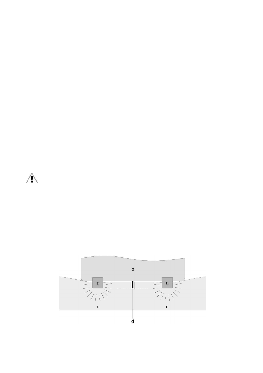
The direct external light irradiation from laser scanners of the same kind (905nm laser
light wavelength) in a line and at th e same installation height can be prevented with
shielding plates at scan level. Shielding, as high as the scanner front screen and flush
with the front housing edge, is sufficient. The same also applies with installation in parallel
alignment and overl apping of the scan levels.
26
Page 27
a = SD3-A1 b = Mac hi ne (view fr om above)
c = Detecti on zones d = Shield plate, flush with the housing
Fig. 5.2-1: Shielding to prevent direct irradiation
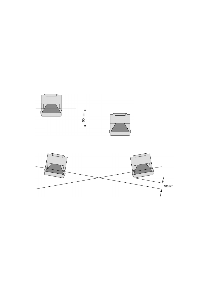
5.2.2
Adjusting adjacent laser scann ers
In order to prevent faulty deactivation and scanners interfering with each other as much
as possible, when using several laser scanners you must install these as shown in the
following examples. Installation on the basis of the MS-SD3-1 m ounting system makes
precise adjustm ent signific antly easier.
Installati on with height offset or a crossed alignment also prevents interferenc e from
beam reflections onto surrounding objects. When safeguarding danger zones, please
also ensure that it is not possible to crawl under the detection zone, so that gaps do not
occur with access guarding.
Fig. 5.2-2: Installation with height offset (parallel alignment)
Fig. 5.2-3:
Installation without height offset (crossed alignment)
27
Page 28

Fig. 5.2-4: Opposing installation without height offset (crossed alignment)
f
5.3 Information on setting the dimensions of detection zones
The hazards caused by machines and systems place a wide range of demands on safety
distances and detection zones which must be appropriately defined.
5.3.1
5.3.2
Methods of configuring detection zones using the PC
With its SD3SOFT configuration and diagnostic software, the SD3-A1 offers various
methods for setting the configurations of detection zones.
Numerical input
A separate dialog within the user program “SD3SOFT” allows the right, left and front
edges of the detection zone to be set using numerical values in mm.
Graphic input
A separate dialog within the user program “SD3SOFT” allows th e basic contours of the
detection zone to be entered. The contours can be adapt ed infinit ely to the desired size o
the detecti on zone. The following shapes are available:
x circle
x rectangle
x polygon
In addition, the contours can be infinitely varied by:
x changing
x limiting and
x deleting
partial segm ents as desired
Range of the detection zone, resolution
The maximum range of the detection zone S
with a diameter of 70mm and a reflectance factor of 1.8% (e.g. bl ack corduroy). The
reference point of the measurement is the axis of the rotating mirror on the scanner
64mm behind the front edge of the scanner.
4m (including the additions) for an object
MAX
28
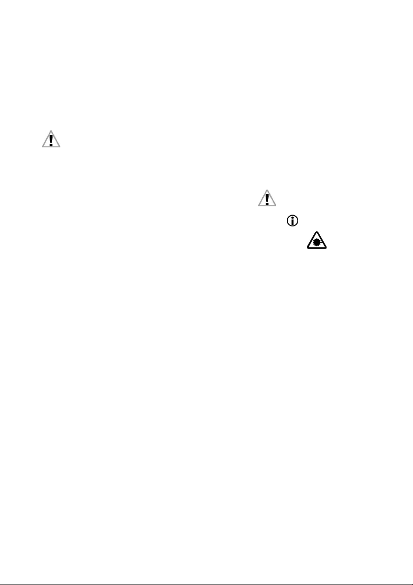
Page 29
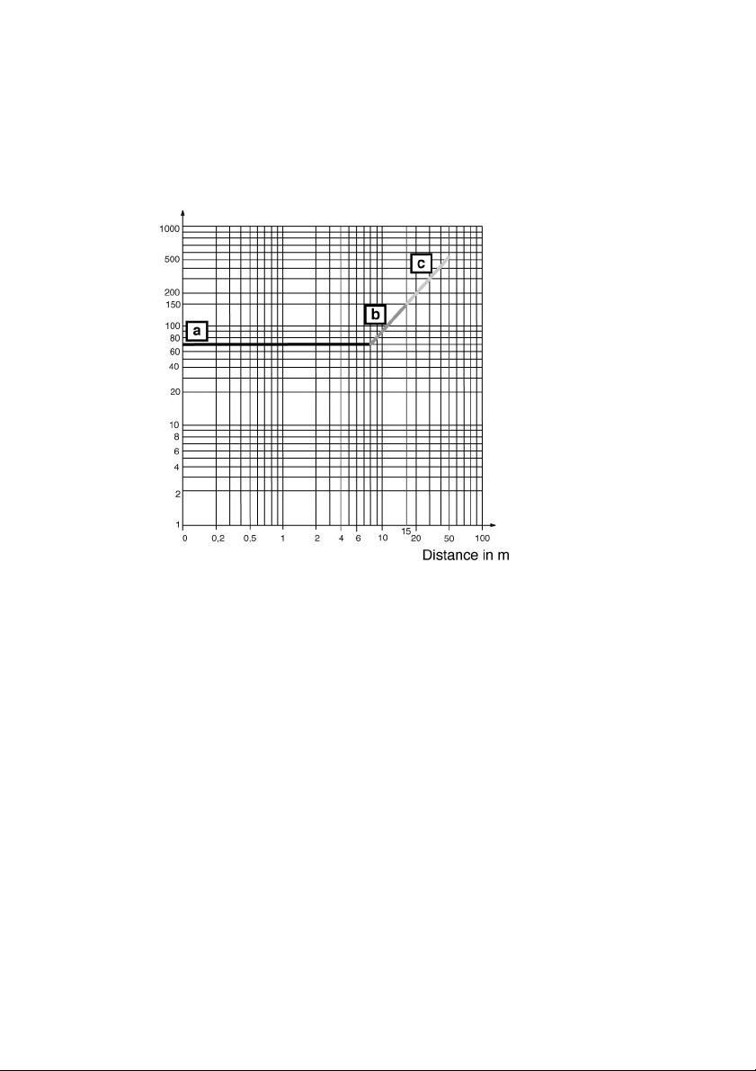
5.3.3
r
Range of the warning zone,
A maximum range of 10m is available for an object with a diameter of 100mm. The
maximum available range for an object with a diameter of 150mm is 15m. Both of these
figur es assum e a reflect anc e f act or of 20%.
Resolution in mm
a = Detection zone
b = Warning zone
c = Measurem ent field
Fig. 5.3-1: Detecting obj ects in the detection zone and in the warning zone. T he
referenc e p oint of t he distanc e meas ur em ent is th e axis of the r ot ati ng
mirror.
esolution
29
Page 30
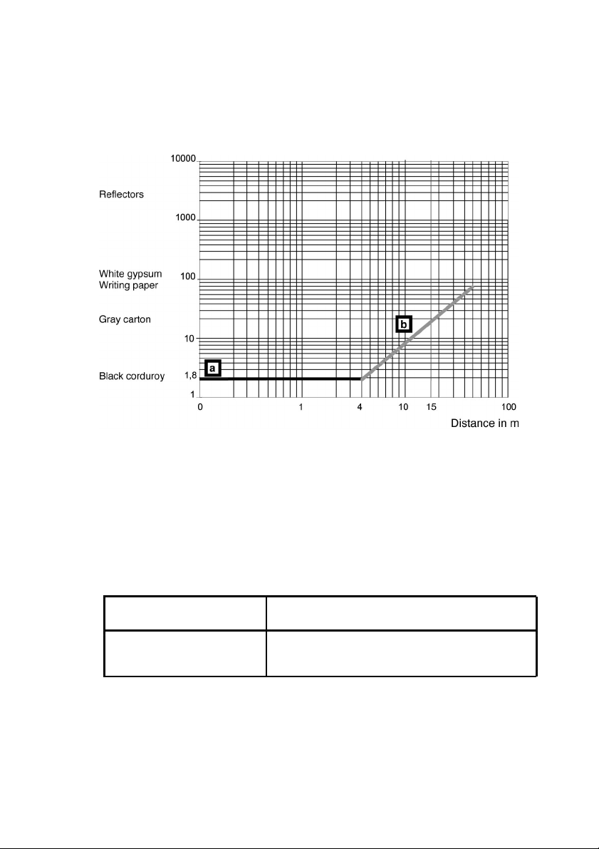
5.3.4
f
Range of the measurement
ield
The maximum distanc e for contour measurement at a reflectance factor of 80% (white
gypsum) is 50m.
Remissi on in %
a = Detection zone
b
= Measurement field
Fig. 5.3-2: Detection of objects depending on the reflectanc e factor. The reference
point of the distance measurement is the axis of the rotating mirror.
5.3.5
Required detection zone additions Z
The SD3-A1 is equipped with a selectabl e dust algorithm to ensure optimum freedom
from int erfer ence.
The following detection zone additions must be taken into account:
Addition Z
suppression is deactivated
Addition Z
suppression is activated
if dust
SM
SM
if dust
83mm
83mm (for a det ection zone size < 3.5m)
100mm (for a detection zone size 3.5m)
Activation and deactivation of the function is perform ed by SD3SOFT.
30
Page 31

If r etro- refl ect or s or very shi ny surfaces, such as p oli sh ed or enam eled metal s or
ceramics, may possibly be present in the scanning plane, the following table applies:
Addition Z
reflectors or very shiny,
surface-treated materials
(e.g. metals and ceramics)
REFL
if retro-
0mm for reflectors more than 1.2m behind the
detection zone line
110mm for reflectors up to 1.2m behind the
detection zone line
are present in the scanning
plane
+ Z
Z = Z
SM
REFL
= Required detection zone addition, in mm
Z
Z
= Measurem ent error of th e sc anner, in m m
SM
= Addition for considering refl ectors, in mm
Z
REFL
5.4 Safeguarding stationary danger zones
Please comply with the safety notes in Chapter 3.
5.4.1
5.4.2
The purpose of safeguarding
is for protection:
x to prot ec t p eople wh en enterin g a danger z on e
x to protect people from reaching a danger point with their extremities
x to protect objects from the danger of collision due to variable machine or part
movements.
Mounting position
The SD3-A1 can be m ounted ei th er in a stati on ar y posit i on ( e.g. on a w all or a m ac hine)
or on moving parts (e.g. machine table).
The qu alified in st all er must en su re that t h e mounting positi on of the SD3-A1 allow s t he
danger zone to be monitored completely.
If a restart button is being used, make cert ain that th e entire detection zone area can be
viewed by the person pressing the button. It must not be possible to activate the button
from t he d an ger area.
Refer to the safety notes in Chapter 3.6 with regard to lateral acc ess into the danger
zone.
31
Page 32

5.4.3
A
r
Mounting height
ccording to DIN EN 999, the lowest admissible height of the scanning plane for people,
as measured from the base level, is calculated according to the following formula:
= 15 × (d - 50mm)
H
MIN
H
= Lowest admissible scanni ng plane from the base level
MIN
d = Resolution of the scanner in mm (object size = 70mm throughout the detection
zone).
5.4.4
The adm issible h eight ran ge o f th e SD3-
A1 scanning plane lies between 0mm
(presettings leg detecti on) and 1,000m m above the base level. If the application requires
a sc anning plane higher t han 300m m , or if c hi ldren have acce ss to the ar ea, th e anal ysis
of the danger zone must consider the h azard caused by persons crawling below the
scanning plane.
Recommendations for mounting to prevent unmonitored zones
Unmonitored zones can result if the scann er is mounted onto a protrudi ng attachment o
if the c ontour of the m achine / syst em is v aried in depth.
32
Page 33

5.4.4.1
Recessed installation (undercut) under the machine table
The undercut must be at least as deep as the zone not monitored by the detection zone
lateral to and in front of the scanner. The minimum depth Z
to recess the scanner, this is allowed up t o a maximum of 40mm ; the depth of the
is 135mm. If it is possible
UMIN
undercut is reduced by the depth value of the recess. If the mounting system is being
used, the necessary dimensions of the undercut depth must be increased acc ordingly
(see Chapter 13.13 and 13.14). The height of the undercut must be limited to prevent
people from being able to step beneath it.
Fig. 5.4-1:
Recessed sc anner installation with undercut
The addition al safeguardi ng required for the particular application must be taken into
account.
Pleas e n ote th at the un der cut m ust c ov er any unm onit ored z on es.
33
Page 34

5.4.4.2
Recessed installation within the machine contour
Furth ermore, th e sc an ner c an b e r ec essed into the cont ours of a m ac hine. The r ec ess
can have a depth of up to 40mm without the mounting system MS-S D3- 1, or up to 65mm
with the mounting system MS-SD3-1. This is in reference to detection zones that cover an
angle range of 180°. If it is not possibl e to comply with these values, or if unmonitored
zon es r es ul t due t o the sha pe or m ov em ent of the machine, addition al safet y m easures
must be taken.
The effectiveness of the detection zones can b e optimized by changing the depth at
which the scanner is inst alled, or by adjusting the angle rang e (e.g. from 180° to 190°).
For inform ation on how to configure the sc anner in thi s way, please refer to the instruction
manual (softw are operation) for the SD3SOFT.
Fig. 5.4-2: Recessed i nstall ation within t he machi ne cont ou r
If it is not possible to mount the SD3-
posi tioned lat eral to or acr os s from the m achine.
34
A1 direct ly onto the m ac hi ne, it c an al so be
Page 35

5.4.4.3
Extern al mounting lat eral to or a cross from the machine
Fig. 5.4-3: Lateral external scanner mounting without an undercut
If t he m achin e c ont ou r runs parallel t o th e 90° beam of t he l at erally plac ed SD3-
distance between the detection zone boundary and the machine may not exceed 35mm.
Fig. 5.4-4: Mountin g the scanner across from the m achine with an undercut
A1, the
35
Page 36

5.4.5
Additions
The axis of the rotating mirror (midpoint of the scanner) is of critical importance when
configuring the detection zones. This axis is assigned a value of 64mm from the front
edge of the sc anner when calculating detecti on zones.
Add 83mm or 100mm for the maxim um radial measurement error Z
Chapter 5.3.5.
Add an addition Z
area.
as described in Chapter 5.3.5 if reflectors c ould be present in the
REFL
as described in
SM
Please note that safety additions must principally be added to the safety distance
throughout the entire detection zone.
In other words, additions may not be added to just one side or only to certain sections.
Please consult the operating instructions provided by the machine or system
manufacturer.
5.4.6
System availability
There must be a buffer distance of 83mm between the surrounding contour and the
detection zone contour (including the additions). This dist ance increases the up-time of
the machine or system since it prevents the surrounding contour from being detected as
relevant for generating a switch-off signal. If there is an undercut across from the scanner
that is impossible for a person to step beneath (see Fig. 5.4-4), the depth of the und ercut
can be calculated according to the following formula:
= Z +83mm - d
Z
UMIN
Z
= Depth of the und ercut, in mm
UMIN
Z = Required detection zone additions, in m m
d = Resolution of the scanner (d = 70mm)
This is possible since it is absolutely certain that a person will be detected in front of the
undercut.
Furth ermore, th e dust al gor it hm of th e SD3-
A1 can be implemented if floating particles
may be present in the area. This algorithm , which can be activated in th e user program
“SD3SOFT”, prevents the machine or system from b eing switched OFF unint entionally.
Please note Chapter 5.3.5.
If the danger zon e analysis allows a multiple evaluation, detection errors caused by
floating particles can be decreased. The number of evaluations that is decisive for the
response tim e of the scanner (T
be set in the user program “SD3SOFT”.
), and thus also requi res a larger detecti on zone, can
SCAN
In the event of an error event that lasts only briefly (for example the effect of extraneous
light) the scann er perform s a one-time reboot. If autom atic startup / restart are activated,
the scanner turns th e OSSDs back ON aft er this brief error event, and after the detection
zone has been free for about 25s. This one-time reboot results in an additional increase
in availability. This function does not have any effect if detection zone activation is faulty.
If startup t est, startup interlock and / or manual restart are included, th ey will not be
removed.
36
Page 37

Safety notes:
Automatic startup / restart must only be used in cases where there is absolutely no
possibility that the effective detection zone could be entered or bypassed in some other
way. D ependin g on th e hazard ass es sm ent, visual an d / or ac ou st ic start up warnings
should be provided.
If parameters are set for the function “Manual restart”, the required enable from the
startup / rest art button affects all detection zones and is ind ependent of any detection
zone changeover. If the current detecti on zone is manually enabled, this enable also
applies even if the system switches to another detection zone and this detection zone
becomes free! If startup / restart interlock is in effect in the current detection zone, it is
als o in ef fect for th e other d et ecti on zone t o which the system swi tc hes even if this
detection zone is free.
5.4.7 Restart interlock
The SD3-A1 is equipped with a restart interlock function. You can select or deselect this
function as needed to connected restarting of the machine to a manual ap proval. It affects
all detection zones and does not depend on any detection zone changeovers. For
information on how to configure the scanner appropri ately, please refer to SD3SOFT
(Section: “Safety-relevant parameters” fold er).
The restart button must be mounted so that
x the entire danger zone (or detection zone area ) can be viewed from the operating
position.
x it is not possibl e to directly step or reach into the danger zone or danger point from
the operating position.
The button refer to the areas to be enabled in a easily understandable manner.
Please comply with th e safety notes in Chapter 3 and 5.4.6.
37
Page 38

5.4.8
f
–
f
Calculating the detection zone dimensions for safeguarding an area
According to IEC 61496-3 and DIN EN 999, the following formulas apply for calculating
the safety distance and the m inimum depth of th e detection zone when th e direction o
approach runs parallel to the detection zone:
C
S = (K × T) + C
C = 1,200mm
S
Safety distance, minimum distance from the danger zone to the point o
=
0.4H
MIN
= 850mm
= 15 (d –50mm)
H
MIN
= 1,000mm
H
MAX
detection, to the plane of detection, or to the detection zone, in mm
K =
Approach speed of a person or a person’s body parts (1,600m m/s), in mm/s
T = Lag time of the entire system (response time and braking time until standstill),
in s
C = Safety-related constant to consider entry into the danger zone before the
protective device is triggered, in mm
C
= Minimum value of the safety-related constant (850m m), in mm
MIN
= Height of the scanni ng plane from the reference point, in mm
H
H
= Minimum height of the scanning plane from the reference plane, in mm
MIN
H
= Maximum height of the scanning plane from the reference plane, in mm
MAX
d
= Resolution of the scanner (70mm throughout the detection zone), in mm
38
Page 39

5.4.8.1
r
r
Additions and minimum depth of detection zone
The sum of the system-specific and application-specific detection zone additions (see
Chapter 5.3.5) is calculated acc ording to the following formula:
= ZSM + Z
Z
TOT
Z
= Sum of the system-specific and applic ation-specific detection zone additions,
TOT
= Scann er m easurement error, i n mm
Z
SM
Z
= Addition of the reflectors taken into account, in mm
REFL
Z
= Addition for application-specific undercut, in mm
AU
REFL
in mm
+ Z
AU
The depth of the detection zone, with reference to the direct distance between the dange
zone and the detection point or line, is calculated according to the following form ula:
= (K × (T
S
T
ST Depth of detection zone, distance from dang er area to detection point or line,
=
K Approach speed of a person or a person’s body parts (1,600m m/s), in mm/s
=
Response time of the scanner, in s
T
=
SCAN
Respons e tim e of th e machine or sy st em , in s
T
=
MACH
Lag time of the entire system, in s
T
=
LAG
Factor for increase in lag time
L
=
LAG
C Safety-related constant, in mm
=
5.4.8.2 Maximum
=
S
S
MAX
S
= G
BDIFF
BDIFF
Maximum range of the detection zone considering the diagonals, in mm
S
=
MAX
Depth of th e detection zone, in mm
S
=
T
S
Largest width of the detection zone between the axis of the rotating mirror
=
BDIFF
G
Largest width of the danger zone betw een the axis of the rotating mirror and
=
BDIFF
S Safety distanc e, minimum distance from the danger zone to the point of
=
Z Required detection zone additions, in mm
=
+ T
+ ( T
× L
SCAN
MACH
LAG
))) + C + Z
LAG
TOT
including system and application-specific additions, in mm
ange of detection zone
2
T
+S
BDIFF
2
+ S + Z
and the outer edge of the detection zon e, in mm
the boundary of the danger zone, in mm
detection, to the plane of detection, or to the detection zone, in mm
39
Page 40

40
Fig. 5.4-5: Considering the maximum measurement di stance when safeguarding an
area
Page 41

5.4.8.3
Sample calculation of the depth of a detection zone
This example is based on the following application data (see 5.4-5):
Largest width between the axis of
the rotating mirror and the
700mm
G
BDIFF
boundary of the danger zone
Access speed K 1,600mm/s (constant)
Response time of the SD3-A1
(adjustable)
Respo nse time of t he machi n e or
system
Stopping time or lag time of the
machine or system
T
0.08s
SCAN
0.1s
T
MACH
T
0.5s (time for braking the
LAG
dangerous movement until
standstill)
Factor for increase in lag time L
Addition for system-specific
measurem en t er ror
Addition caused by the mounting
position that is selected
1.1 (fixed addition to account for
LAG
Z
83mm (when dust algorithm is
SM
125mm (distance betw een the
Z
AU
increased lag time)
switched OFF)
front edge of the undercut to the
beam axis of th e sc anner)
Height of the sensor
H 300mm
scanning plane
Safety-rel ated const ant C 1,200mm – 0.4 × Height H
= 1,080mm
The formul a
S = ( K × ( T
SCAN
+ T
MACH
+ ( T
LAG
× L
LAG
))) + C
results in a safety distance of:
S = (1,600mm/s × (0.08s + 0.1s + (0.5s × 1.1))) + 1,080mm = 2,248mm
The formul a
S
= S + ZSM + Z
T
AU
results in the detection zone depth:
= 2,248mm + 83mm + 125mm = 2,456mm
S
T
41
Page 42

5.4.8.4
r
2
2
2
Sample calculation of a maximum
ange of a detection zone
The formul as:
=
S
S
MAX
BDIFF
= G
BDIFF
S
T
+S
BDIFF
+ S + Z
SM
yield, under consideration of the width of the danger zone results in the maximum
distance to be monitored:
S
MAX
=
2,456mm2 + 3,031mm
= 700mm + 2,248mm + 83mm = 3,031mm
S
BDIFF
= 3,901mm
S
MAX
5.4.8.5
Sample calculation of an undercut
This example is based on the following applicati on data. If the scanner is mounted across
from the machine (see Fig. 5.4-4), the undercut dimension c an be reduc ed by d = 70mm.
The formul a
Z
= Z + 83 mm – d
UMIN
results in a minimum undercut:
= 83 mm + 83 mm – 70 mm = 96 mm
Z
UMIN
It is not allowed for a person to be able to step beneath the undercut.
Fig. 5.4-6: The undercut
42
Page 43

5.5 Access protection
r
Please have regard to the general safety notes in Chapter 3.
5.5.1
5.5.2
5.5.3
Object of protection
The object of protection is the safeguarding
x of individuals when they access a danger zone.
The SD3-A1 will detect the passage of individuals and the intrusion of an entire human
body into the scanning fi eld of the laser scanner.
Installation position
Access protection is based on passage monitoring. This is a suitable system when the
access to a machine or to a hazardous zone can be precisely defined in structural terms,
and there is no other unprotected access to the area. In addition, the danger area must
be open to inspection, and the button for manual triggering of the restart interlock must
be situated outside the area. It is best if the laser scanner is firmly installed above the
passage in question, in vertical alignment and in such a way that it cannot be manipulated.
Care must be taken to ensure that the positioning of the laser scanner SD3-A1 does not
leave any areas through which a person might slip through without being detected. The
distance of the scanning field limiting the passage and the boundaries of the detecti on
zone must be defined in such a way that no gaps measuri ng more than 150mm can arise.
Safety-relevant settings, and calculation of the safety distance
To safeguard the protective equipment against inadvertent misadjustment o
manipulation, the detection zon es of the SD3-A1 must be defined on the basis of a
reference boundary. In addition, the response time must be defined as 80ms and the
restart interlock must be set.
To enable the system to recognize an entire human body, the laser scanner must have a
resolution of 150mm. These safety-related settings will be automatically enabled in the
SD3SOFT configuration and di agnosis software when the presetting ”Passage
monitoring” has been selected.
For effective passage monitoring, a safety distance S must be observed between the
detection zone of the laser scanner and the danger zone. The SD3-A1 can fulfill its
protective function only if it has been installed and positioned in such a way as to allow for
an adequate safety distance. The safety distanc e ensures that no body part whatever can
reach the danger point until the hazardous movem ent of the machine has com e to a
complete standstill.
43
Page 44

The safet y distanc e f or a n ac c ess prot ecti on system may be c alculat ed, based on EN 999
r
by means of the following formula:
S = K × T + C
S = Safety distance, in mm
K = Approach velocity, in mm/s Here = 1,600mm /s
Overall time of delay, in s,
T =
a total consisting of:
Respo nse time of t he lase r sc an ner Here = 80m s
Overtravel time of the machine including the
controls
C =
Added margin on account of the possibility
of manual intrusion
Please also have regard, in this connection, to the diagrams gi ven in this chapter.
5.5.4 Definition of the
eference b oundary
Bas ed on measu r em ent of
overtravel time
Here = 850mm
Fig. 5.5-1: Access protection by passage monitoring with system check of a
reference boundary
44
Page 45

The reference boundary must cover at least two sides of the detection zone. The
r
r
f
detection zone itself must be defined in such a way that no gaps can arise through which
a pers on could pass t hr ou gh th e passage w it hout b ei ng detect ed. The r ef er ence
boundary is defined with reference to the non-moving parts of the passage. These will
then be constantly monitored by the laser scanner, so that any indi viduals intruding or
other manipulative intervention will be detected beyond the possibility of doubt. In defining
the reference boundary, please also have regard to the indications given in the instruction
manual (software operation) for the SD3SOFT configuration and diagnosis softw are.
5.6 Protecting danger points
Please have regard to the general safety notes in Chapter 3.
5.6.1
5.6.2
5.6.3
Object of protection
The object of protection is the safeguarding
x of indi viduals who work with a machine or spend time in th e danger zone
associated with it.
The SD3-A1 will detect the body parts of individuals and the intrusion of these body parts
into the sc anning fi eld of the laser scanner. In this op erating m ode, hand and arm
protec tion is effec ti vel y realised.
Installation position
Safeguarding of danger points on the basis of hand and arm protecti on is a suitable
met hod if the m achine op era tor, in c l ose pr oxim it y t o th e danger zone, n eeds to h alt the
hazardous m ovement of the machi ne or t o coordinate the handling of workpieces or thei
rem ov al f rom t he m achi ne. It is best if the l as er scann er is firmly inst all ed ab ov e th e
danger zone, in such a way that it cannot be manipulated. The health and safety office
must ensu r e th at th e inst all ation p osi ti on of t he SD3-A1 does not leave any areas free
through which manual intrusion could be effected. If appropriate, additional protective
facilities should be installed to exclude any possibility of the operator’s reaching over or
around or getting behind th e barrier. To prevent the latter, the dist ance from the scanning
field to the machine table must not be more than 75mm. This can be guaranteed i
suitable screen s are installed for the monitoring of the reference boundary (see the
illustrations in this chapter).
Safety-related settings, and calculation of the safety distance
In order to safegu ard the protective equipment against inadvertent misadjustment and
manipulation, the detection zon es of the SD3-A1 must be defined on the basis of a
reference boundary. To make it possible to recogni se the hand or arm of a person, the
laser scanner must have a resolution of 30 or 40mm. These safety-related values will be
automatically set in the SD3SOFT configuration and di agnosis software when the
presetting “Hand protecti on” or “Arm protection” has been selected. At the same time the
detection zone limits will be limited to 1.60m or 2.20m, and cannot be extended beyond
this.
45
Page 46

To safeguard the danger point, a safety distance S must be observed between the
A
C
detection zone of the laser scanner and the danger zone. The SD3-A1 can fulfill its
protec tive fu nc ti on onl y if it has been inst all ed an d p osi tion ed in such a w ay as to all ow for
an adequate safety distance. The safety distanc e ensures that no body part whatever can
reach the danger point until the hazardous movem ent of the machine has come to a
complete standstill.
The safety distance S when safeguarding a danger point may be calculated, based on EN
999, by means of the followi ng formula:
S = K × T + C
S = Safety distance in mm
K = Approach velocity in mm/s
At a close distance of 500mm, a velocity of 2,000mm/s should be assum ed.
If the calcul ation involves a distanc e in excess of 500mm, K may be taken
to be 1,600m m/s. But in this case the safety distanc e is subject t o a
minimum value of 500mm.
Overall time of delay in seconds,
T =
a total consisting of:
Response tim e of the laser scanner Adjustable, max. 200ms
46
Overtravel time of the machine including the
controls
C = 8 × (d - 14 ) in mm
dded margin dep endent on the depth of penetration of the detection zone,
based on the resolution of the laser scanner: C (30mm) = 128mm,
(40mm) = 208mm
The resol ut ion t o whic h t he l as er sc anner
d =
has been set
In this connection please also have regard to the illustrations given in this chapter.
Bas ed on measu r em ent of
overtravel time
Here = 30mm or 40mm
Page 47

5.6.4
r
Defining the
eference boundary
Fig. 5.6-1:
The reference boundary m ust cover at least two sides of the detection zone. The
detection zone itself must be defined in such a way that no gaps can arise through which
or over which a person could reach without being detected. The detection zone must also
provide safeguards against a person getting b ehind the barrier. This can be very
effectively managed by screening th e sides of the danger zone. The reference boundary
should be defined with reference to the non-moving parts of the screen arrangement.
The detecti on zone must be defined as large enough to ensure an overlapping greater
than the tolerance zone of the reference bound ary. The detection zone will then be
constantly monitored so that any body parts intruding or other manipulative intervention
will be detected beyond the possibility of doubt. In defining the reference boundary,
please also have regard t o the indic ations given in the instruction manual (softw are
operation) for the SD3SOFT configuration and diagnosis software.
Safeguarding of danger point based on hand and arm protection with
monitoring of a reference boundary
47
Page 48

5.7 Safeguarding mobile machines
A
A
Please comply with the safety notes in Chapter 3.
5.7.1
5.7.2
5.7.3
5.7.4
The purpose of safeguarding
is for protection:
x to protect people when entering vari able danger zones
x t o prot ec t obj ect s l oc at ed in the vehic le p at h
x t o prot ec t t he aut om atic guide d vehi cl e and its load
Installing adjacent laser scanners
The SD3-A1 has been developed in a way that prevents several laser scanners from
interfering with one other as much as possible.
An increase in the response time can, however, be caused by the installation of several
adjacent laser scanners. If none of the constructive measures (section 5.2.1) described
in the following sections or the specific adjustment (section 5.2.2) are implemented, then
the SD3-A1 response time set and shown in the configuration and diagnos is
software (SD3SOFT) is extended by 40ms. This ext ension in the response time must
be taken into account when calculating the safety distance!
Mounting position
For the purpose of safeguarding the path of a vehicle, the SD3-A1 is mounted on the
front of a vehicle (in each dir ection of travel), preferably in the center.
The scanner, and henc e the beam axis, m ust be aligned horizontally in order to achieve a
consistent scanning height.
Please comply with the safety notes in Chapter 3.7.
Mounting height
s a rule, the sc anner should be mount ed as low as possible in order to prevent people
from c rawling b en eat h th e detection zon e. This spec i fic at i on is limited du e t o suc h f acto rs
as uneven floors or the deflection of the springs in the AGV.
The maximum mounting height must be select ed so that an object (cylinder with a
diameter of 200mm in the prone position) i s reliably detect ed (see DIN EN 1525). The
detection must be tested at the position of maximum depth within the detection zone. For
GV applications, sufficient resolution of detecti on is achieved when a n object (upright
cylinder) with a diameter of 70mm can be detected throughout the detection zone.
48
Page 49

Fig. 5.7-1:
f
Depending on the application, further additi ons may be necessary. Additi onal inform ation
is available in Chapter 5.7.6.
Mounting height on an AGV
5.7.5
Recommendations for mounting to prevent unmonitored zones
The creation of unmonit ored zones is dependent upon the following fact ors:
x the vehicle width
x the design of the vehicle (e.g. attachments, shape)
x the position of the scanner
x the installati on depth
x the selected angle range.
If the detection zone of a SD3-A1 mounted on an AGV does not cover the entire front o
the vehicle, you can prevent the creation of unm onitored zones by changing the
installati on depth of th e scanner or by adjusting the angl e range (from 180° to 190 °).
49
Page 50

If this is not possible due to constructional limitations, additional safety measures such as
mechanical cover pan els, switch strips or bum pers must be implemented.
Please comply with the safety notes in Chapter 3.7.
50
Fig. 5.7-2: Three possibilities for mounting the SD3-A1 onto an AGV
Page 51

5.7.6
Additions
The axis of the rotating mirror (midpoint of the scanner) is of critical importance when
configuring the detection zones. This axis is assigned a value of 64mm from the front
edge of the sc anner when calculating detecti on zones.
Add 83mm or 100mm for the maximum radial measurement error Z
Chapter 5.3.5.
Add an addition Z
area.
as described in Chapter 5.3.5 if reflectors could be present in the
REFL
as describ ed in
SM
Without information from the AGV manufacturer, take int o account the wear and tear on
the brakes by adding an addition L
this is not already included in the braking distance S
of at least 10% of the braking distance, as long as
STOP
STOP
.
If there is a very sm all distance between the bottom of the AGV and the floor, the
detection differenc e between the leg and the toes must be considered in the calculation.
For AGVs with a floor clearanc e of less than 120mm, an addition Z
This refers only to the travel of direction.
must be added.
AFLR
Fig. 5.7-3:
Diagram for calculating the addition to compensate for inadequate AGV
floor clearance
51
Page 52

5.7.7
f
A
t
r
System availability
There must be a buffer distance of 83mm between the surrounding contour and the
detection zone contour (including the additions). This dist ance increases the up-time o
the AGV, since it prevents the surrounding contour from being detected as relevant for
generating a switch-off signal due to a measurement error.
Furth ermore, th e dust al gor it hm of th e SD3-A1 can be implem ented if floati ng particles
may be present in the area. Thi s algorithm can be activated in the user program
“SD3SOFT” and prevents the AGV from being switched OFF unintentionally. Please note
Chapter 5.3.5.
If the danger zon e analysis allows a multiple evaluation, detection errors caused by
floating particles can be decreased. The number of evaluations that is decisive for the
response tim e of the scanner (T
be set in the user program “SD3SOFT”.
), and thus also requi res a larger detecti on zone, can
SCAN
In the event of an error event that lasts only briefly (for example the effect of extraneous
light) the scann er perform s a one-time reboot. If autom atic startup / restart are activated,
the scanner turns th e OSSDs back ON aft er this brief error event, and after the detection
zone has been free for about 25s. This one-time reboot results in an additional increase
in availability. This function does not have any effect if detection zone activation is faulty.
If startup t est, startup interlock and / or manual restart are included, th ey will not be
removed.
Safety notes:
Automatic startup / restart must only be used in cases where there is absolutely no
possibility that the effective detection zone could be entered or bypassed in some other
way. D ependin g on th e hazard ass es sm ent, visual an d / or ac ou st ic start up warnings
should be provided.
If parameters are set for the function “Manual restart”, the required enable from the
startup / rest art button affects all detection zones and is ind ependent of any detection
zone changeover. If the current detecti on zone is manually enabled, this enable also
applies even if the system switches to another detection zone and this detection zone
becomes free! If startup / restart interlock is in effect in the current detection zone, it is
als o in ef fect for th e other d et ecti on zone t o which the system swi tc hes even if this
detection zone is free.
5.7.8 Restart
t least 2s m ust el apse following th e release of a vi olated d et ect i on z on e befor e the A GV
is allowed to startup again (in accordanc e with DIN EN 1525). The rest art can be initiated
either manually or automatically. In case of automatic restart, the delay time of up to 10s
can be set in advanc e using the program “SD3SOFT”. If a restart butt on is provided, i
must be mounted outsid e the danger zone at a position from which the entire dange
zone can be viewed. The areas that will be released must also be referred to in an easily
understandable manner. The st artup / restart interlock affects all detection zones and
does not depend on any detection zone changeovers.
Please comply with the safety notes in Chapter 3 and Chapt er 5.7.7.
52
Page 53

5.7.9
f
V
V
V
Z
Z
R
Z
r
2
2
Calculating the dimensions of the detection zone of an AGV application
Following are the specificati ons and calculation examples for the mobile safeguarding o
automatic guided vehicles..
According to IEC 61496-3, the following form ulas apply for calculating the safety dist ance:
5.7.9.1
5.7.9.2
S = (V
V
MAXAGV
T
S
STOP
× T) + S
MAXAG
STOP
Maximum speed of the AGV, in mm/s =
Respo nse time of t he sc anner an d t he AGV , in s
=
Braking distance of the AGV until standstill, in mm
=
Direction-related minimum depth of the detection zone and additions
The depth of the detection zone in the direction of travel, with respect to the distance
between the edge of the roadway and the boundary of the detecti on zone, is calculated
acc ording t o the following formula:
S
= V
T
S
T
V
MAXAGV
T
SCAN
T
AGV
L
STOP
Z
TOT
Z
TOT
×( T
MAXAG
Depth of the detection zone in the direction of travel, in mm
=
SCAN
+ T
) + ( S
AG
STOP×LSTOP
) +
TOT
Maximum speed of the AGV, in mm/s =
Response time of the scanner, in s
=
Response time of the AGV, in s
=
Fact or for wear and tear on th e brakes
=
Total of the system- and application-specific additions in the direction of
=
travel in mm
= ZSM + Z
REFL
+
+
AFL
AU
ZSM = Scann er m easurement error, i n mm
= Addition of the reflectors taken into account, in mm
Z
REFL
Z
AFLR
Z
AU
Maximum
S
MAX
Addition for inadequate floor clearance by the AGV, in mm
=
= Application-specific addition, in m m
ange of detection zone
S
=
T
+S
BDIFF
= G
S
BDIFF
S
= Maximum range of the detection zone, in mm
MAX
S
= Depth of the detecti on zone in the directi on of travel, in mm
T
S
BDIFF
G
BDIFF
Z
= Sum of the system- and applic ation-specific additi ons to the side, in mm
S
= ZSM + Z
Z
S
SM
Z
REFL
= Application-specific addition, in m m
Z
AU
+ Z
BDIFF
S
Largest width of the detection zone, in mm
=
Largest width of the danger zone, in mm
=
+ Z
REFL
AU
= Scan ner m easurem ent err or, in mm Z
= Addition of the reflectors taken into account, in mm
(see Chapter 5.3.5)
53
Page 54

54
Fig. 5.7-4:
In accordanc e with DIN EN 1525, a minimum safety distance of 0.5m width b etween the
vehicle and its environment must be maintained.
Considering the maximum measurement dist ance for safeguarding
AGVs
Page 55

5.7.9.3 Sample calculation of the depth of a detection zone
V
V
F
2
2
2
2
Thi s exam pl e is based on th e foll owing typic al applic ation dat a (with out ac cess against
the directi on of travel and without retro-refl ectors):
Largest width of the danger zone
from the axis of the rotating mirror
Maximum speed
Response time SD3-A1 (sel ectabl e)
Response time of AGV control
Braking distance
Factor for wear and tear on the brakes 1.1 (fixed addition to acc ount for
Measurem en t er ror
Distance between AGV and floor = Z
= G
BDIFF
= V
MAXAGV
= T
SCAN
= T
AGV 0.1s
= S
STOP
= L
STOP
= Z
SM 83m m
90mm (results in an additi on of
AFLR
1,400mm
1,800mm/s
0.08s
1,900mm
wear and tear on the brakes)
50mm accordi ng to Fig. 5.7-3 for
calculating the addition for
inadequate floor clearance)
5.7.9.4
The formul a
S = V
MAXAG
SCAN
) + (S
AG
STOP
× L
STOP
)
× (T
+ T
results in a safety distance of:
S 1,800mm/s × (0.08s + 0.1s) + (1,900mm × 1.1)
=
= 2,414mm
The formul a
S
= S + ZSM + Z
T
REFL
+ Z
AFLR
+ Z
AU
results in the following required depth of the detection zone in the direction of travel:
= 2,414mm + 83mm + 0mm + 50mm + 0mm = 2,547mm
S
T
Sample calculation of a maximum range of a detection zone
The formul a
MAX
T
BDIFF
= G
S
BDIFF
BDIFF
+ Z
S
S
+ S
=
S
yields, under consideration of the width of the danger zone results in the maximum
distance to be monitored:
S
MAX
S
BDIF
S
MAX
2,547mm
=
= 1,400mm + 83mm = 1,483mm
=
2,947mm
+ 1,483mm
55
Page 56

5.7.10
r
f
o
Side guarding configuration on AGVs
All previous considerations and the Chapt er 5.7.9 (Calculating the dim ensions of the
detection zone of an AGV applicati on) also apply for sid e guarding on AGVs. With AGVs
that drive along conveyor segments it should always be ensured that big enough
undercut is provided (see also, details in Chapter 5.4.4). If the structure of the conveyo
segment does not allow an undercut, then it must be assumed that a person is in the
space between the vehicle and the conveyor. This is especially the case with spaces o
mor e than 100m m . This pers on i n t he sp ac e b etw e en v ehic le and c onveyor shoul d be
detected simultaneou sly with a person in the driveway, which must be taken int
consideration with the dimensioning of the detection and w arning zones.
The same safety distance calculations therefore apply.
A laser scanner resolution of 150m m is required to detect an entire person. This safetyrelevant setting is automatically set in the SD3SOFT configuration and diagnostics
software with selection of the "person detection" presetting. The definition of a referenc e
contour as with acc ess guarding i s not necessary, as the approach of th e person to be
protected is made in the direction of the detection zone! If the conveyor segment height is
over 500mm and the dist ance between vehicl e and conveyor is mor e than 100m m, then
the detecti on zone between vehicl e and conveyor can be aligned. With conveyor segment
heights below 500mm there is the increased danger of the conveyor segm ent being
crossed over. In this case the alignment of the detection zone with the conveyor edge
guarantees detection of a person at this point. If a laser scanner resolution finer than
150mm is additionally required for the safe position detection of the load, then this can
also be selected in this application. The person in the in between space continues to be
safely detected.
56
Page 57

6 Details on Switching Over Detection and Warning Zones
A
y
During the course of an optimum machine utilization an alternate infeed or machining
cycle often occurs, which brings the most diverse danger areas with it.
vehicle system applications by their very nature include various danger areas, depending
on the o per ating st at us. I f the appr oac h or pr es ence of p eop le is now to be expect ed i n
these areas, the need exists of a precisely adjusting safety system. With its eight
switchabl e and freely configurabl e detection and warning zones (zone pairs), the SD3-A1
satisfies m ultifaceted requirements with regard to guarding the most diverse applications.
The definition of the necessary zone pair cont ours is possible with the convenient and
easy to use configuration and diagnostics softw are, "SD3SOFT".
The zone p air s are act iv at ed via the con nect ion of 24V DC to t he corre spondin g c ont rol
inputs, FP 1 to FP 4, which are provided on the X1 plug of the scanner. Please find
detailed information on the scann er connection in Chapter 7.2 and Chapter 9.
If the SD3-A1 is to be restarted or switching is to be made between different zone pairs,
the following points must be observed:
x The zone pair planned for the start must be defined with speci al consideration of the
danger areas valid for this moment.
x The sequence of the monitoring zones to be activated must ensure that the lower
threshold of the application-related detecti on zone minimum values is never
crossed.
x W ith selecti on of zone pair 8 the monit oring function of the scanner is deactivated,
i.e. no detection zones are monit ored and the safety outputs (OSSDs) remain
constantly active! With zone pair 8 the laser scanner may not be started. Zone pair 8
is planned for application-related situations in which it has been absolutely ensured
that there is no danger for any people present. These are, for exampl e, vehicl es with
crawler mode or in completely partitioned OFF and secured areas, vehicles in
approach mode in the area of loading or p arking positions, as well as machines in
the " s etu p" op er ati ng mode.
utom ated gui ded
Please observe the connection and interface assignment in Chapter 9.5 and the safet
notes in Chapter 3.
6.1 Sequence of zone pair switchovers
The SD3-A1 safety laser scanner has eight detection / warning zones. Switchover
between these zone pairs is possible at all times, provided the operating situation allows
this. During the switchover process the SD3-A1 monitors the zone pair activated before
the switchover until a new one has been clearly activated. Th e rules for the switchover
depend on th e amount of the select ed zone pairs and their num bers. The procedures
described in the followin g tables apply.
57
Page 58

Table 6.1-1 applies with activation (start or switchover) of zone pairs 1 to 8.
r
Zone pai
1 1 - 0 - 0 - 0 Zone pair 1 is active
2 0 - 1 - 0 - 0 Zone pair 2 is active
3 0 - 0 - 1 - 0 Zone pair 3 is active
4 0 - 0 - 0 - 1 Zone pair 4 is active
5 1 - 1 - 1 - 0 Zone pair 5 is active
6 1 - 1 - 0 - 1 Zone pair 6 is active
7 1 - 0 - 1 - 1 Zone pair 7 is active
8 0 - 1 - 1 - 1 Zone pair 8 is active
Table 6.1-1: Connection of control inputs FP 1 to FP 4 with activation of zone pairs
The foll owi ng poi nt s als o appl y f or th e switch over:
x T he swi tc hover m ust be m ad e w it hin 40ms, i.e. aft er 40ms one of the inp ut
x The switchover process executed by the control unit must concur with the laser
If these points are not observed the laser scanner will fail within 40ms and will show this
with the additi onal 2Hz flashing of the green LED 1.
Control input
FP 1 – FP 2 – FP 3 – FP 4
1 to 8
connections shown in Table 6.1-1 must be valid and provided stable. During the
switchover time the old zone pair is monitored; the new one after max. 80ms.
scanner’s configuration, which was set beforehand with SD3SOFT.
58
Page 59

6.2 Practical AGV application (example)
r
The foll owi ng exampl e sh ows the sequenc e of zone pai r c hang eo vers for an ef fic i ently
implemented AGV under consideration of the ambi ent conditions. Please observe the
particular danger zone analysis for each detection zone in combination with the
correspondi ng route segm ents. Also note the safe sequences of changeovers and starts.
For information on programming the startup detection zones (detection zones enabled for
starting up the scanner) and on determ ining the sequence in which the detection zon es
are to be activated, please see the instruction manual (software operation) for the
SD3SOFT.
Activating
an ZP
ZP 1 Straight secti on High speed
ZP 2 2m before the curve ZP 1 Low speed
ZP 3 Beginning of the curve ZP 2 Steering l ock - curve
ZP 1 Straight secti on ZP 3 Steering lock - straight
FP = 1 × detection zone + 1 × warning zone
Table 6.2-1:
If the AGV is controlled by a PLC, for instance, which corresponds t o Category 3 or
higher acc ording to DIN EN 954-1, the previous zon e pair (ZP) can be deactivated
immediately after the next zone pair has been activated, with no time delay.
This results in a faster switching sequence.
The applic able safety guidelines and standards as well as the operating instructions fo
the syst ems m ust be strictly complied with.
AGV position Deactivating
an ZP
Practical AGV application
AGV control of
position
High speed
59
Page 60

60
Fig. 6.2-1: E xam pl e of a zon e pair changeov er for an AGV on a cur ve d ro ut e
Page 61

Fig. 6.2-2: Example of zone pair changeover with combined with reducing speed of
the AGV
61
Page 62

7 Functions of the SD3-A1
The SD3-A1 is equipped with the X1 and X2 interfaces. The following functions are
available through them:
7.1 Restart
Depending on the operating state, the restart inp ut X1-2 has several functions:
x E nables t he restart interl ock foll owi ng th e int err upti on of a d et ecti on zone
x E nables t he start in terl ock foll owi ng a s yst em st art
x Restarts after a devic e error has been eliminated
x Recognizes a defined enable signal
after a devi ce error
after a detection zone interruption for enabling the restart interlock
To activate the functions, apply 24V to input X1-2. In the meantim e, the safety outputs
OSSD 1 and OSSD 2 are switched OFF; the indicator at the scanner (LE D 3) is lit up red.
The duration of the signal must be between 0.12s and 5s.
The restart input X1-2 must be connected to an external, perm anently installed button.
X1-2 must not be connected with the remaining c ontrols in order to prevent an unintended
release with a restart pulse under some circum stances.
Force-guided, norm ally closed contacts c an be monitored in the rest art circuit (relay
monitoring).
Please note the Chapter 5 (Inform ation for Planning and Mounting) and 9.1 (Electrical
power supply).
7.2 Channels for zone pair changeovers, FP 1 to FP 4
To activate the zone pairs, apply 24V (see Chapt er 9.1) to the following inputs:
x X1-4 (FP 1)
x X1-6 (FP 2)
x X1-7 (FP 3)
x X1-8 (FP 4)
The following points also apply for the switchover:
x T he swi tc hover m ust be m ad e w it hin 40ms, i.e. aft er 40ms one of the inp ut
connections shown in Table 6.1-1 must be valid and provided stable. During the
switchover time the old zone pair is monitored; the new one after max. 80ms.
x The switchover process executed by the control unit must concur with the laser
scanner’s configuration, which was set beforehand with SD3SOFT.
If these points are not observed the laser scanner will fail within 40ms and will show this
with the additi onal 2Hz flashing of the green LED 1.
62
Page 63

7.3 Alarm 1 (X1-5)
As long as the output X1-5 is switched ON, the syst em signals trouble-free operation.
If it i s sw it ched OFF, the f ollow ing states are r ep orted :
x Interrupti on of the warning zone is shown by the continuously lit LE D 2 in the
indicator field of the scanner.
x W arning state:
For instance, the system m ay detect a slight dirt buildup on the optical window. To
signal this state, LE D 5 on the scanner flashes (2Hz). The user should clean the
optical window before it gets dirti er; waiting too long will cause a device error to be
reported and the outputs OSS D 1 and OSSD 2 to be switched OFF.
x Device error:
Such as an erroneous reference measurem ent or extreme dirt buildup on the optic al
window. This state is signaled by LED 5 flashing quickly (4Hz).
Both the reporting of a warning zone int errupti on and the si gnaling of the warning and
err or state can be sel ected eith er s eparately or i n combin ation. Thi s proc edure is
described in the instruction manual (softw are operati on) for the program “ SD3SOFT”.
Output X1-5 is equipped with an internal electronic current limit to protect it against
damage from overload.
7.4 Alarm 2 (X1-15)
As long as the output X1-15 is switch ed ON, the syst em signals trouble-free operation.
If it i s sw it ched OFF, the f ollow ing states are r ep orted :
x W arning state:
For instance, the system m ay detect a slight dirt buildup on the optical window. To
signal this state, LE D 5 on the scanner flashes (2Hz). The user should clean the
optical window before it gets dirti er; waiting too long will cause a device error to be
reported and the outputs OSS D 1 and OSSD 2 to be switched OFF.
x Device error:
Suc h as an err oneou s r ef er enc e m easurem ent or ext rem e dirt buildup on the opt ic al
window. This state is signaled by LED 5 flashing quickly (4Hz).
Out put X1-15 i s equipp ed wi th an intern al elec tronic curr ent lim it to pr otect it again st
damage from overload.
63
Page 64

7.5 OSSD 1 (X1-12) and OSSD 2 (X1-11)
c
r
When the det ection zone is int errupted, the two semiconduct or outputs switch OFF and,
by way of elements such as positively guided relays, cause the monitored machine(s) to
shut down.
It is not admissible to control different safety circuits with a single OSSD. Connected
loads must exhibit a low-pass behavior in accordance with the plausibility control
conducted by the scanner (f
anint er nal el ec tr onic current li mit t o pr ot ect them against dam age from ov erload.
For some sample connections, see Chapter 8.
1kHz, CL 100nF). The OSSDs are equipped with
g
7.6
Data
ommunication
The int er face X2 all ow s t he SD3-A1 to support two types of connections to the PC.
Com m unicati on via t he X2 c onn ector in RS -232 mod e does not require any furth er
bridging. T o enable data transfer in RS-422 mod e, connect pi n 5 with pin 6. The scanner
automatic ally adjusts itself to the appropriate transfer type and baud rate.
The int er face (X2) i s used for
x configuring and setting parameters for the SD3-A1
x transferring measurement data while the scanner is in op eration
x evaluating the coordinates during p arameter setting (e.g. for AGV applications)
x advanced status and control diagnostics.
Guard operation is only permitted with the PC cable (X2) or dumm y connected screwed
ON. This also applies for transport and storage.
Please note the pin assignments specified in Chapter 9.5. For additional information on
using th e X2 interf ac e, r ef er to th e inst ru ct ion m anual (s oftw are op er atio n) for th e
program “SD3SOFT”.
8 Integrating the SD3-A1 into Machine Controls
The following examples illustrate possibilities for integrating the SD3-A1 into machine
controls.
Once the operating voltage pin X1-3 (+U
detection zone has been activated (X1-4, X1-6, X1-7 or X1-8), the unit is ready fo
operation.
Please see the point “Define Detection / Warning Zones” in the instruction manual
(so ftware operati on) fo r the p rogr am “SD3SOFT”.
) has been connected to pin X1-1 (GND) and a
B
64
Page 65

8.1
Integrating the SD3-A1 with external wiring with relays and
eightfold zone pair changeover
In this connection example, the restart interlock function is provided by the connected
command unit “st art interlock”, which applies the voltage of 24V to the input RESTART
X1-2. The SD3-A1 itself must be configured using the “SD3SOFT” user software so that
the op er ati ng mode “with rest art int erl ock” i s ac tive.
Fig. 8.1-1: W iring the SD3-
and restart interlock (example)
Relays K1 and K2 must have forced contacts. They are operated directly at the two
failsafe semiconductor outputs OSSD 1 (X1-12) and OSSD 2 (X1-11).
Relay K3 has a deenergizing delay. A suitable mechanism must be provided for
extinguishing sparks. Please note that doing this will cause the switching time to be
extended.
Channels “x” and “y” must be integrated for Category 3 in accordanc e with DIN EN 954-1.
Integrating one channel based on “z” is only permitted with a one-channel control system
and taking int o consideration the results of a risk analysis.
Serial machine controls are admissible only insofar the valid regulations allow.
A1 with evaluation of the OSSDs, zone pair chang eover
65
Page 66

66
Fig. 8.1-2: W iring the SD3-A1 with evaluati on of the OSSDs, zone pair changeover,
restart interlock and static relay monitoring
Relays K1 and K2 must have forced contacts. They are operated directly at the two
failsafe semiconductor outputs OSSD 1 (X1-12) and OSSD 2 (X1-11).
A suitable mechanism m ust be provided for extinguishing sparks. Please note that doing
this will cause the switching time to be extended.
Channels “x” and “y” must be integrated for Category 3 in accordanc e with DIN EN 954-1.
Integrating one channel based on “z” is only permitted with a one-channel control system
and taking int o consideration the results of a risk analysis.
Serial machine controls are admissible only insofar the valid regulations allow.
Page 67

8.2
r
Connecting the SD3-A1 to a safety sequence circuit with
manual restart interlock, relay monitoring, without zone pai
changeover
Fig. 8.2-1: W iring the SD3-A1 with manual restart int erlock and relay monitoring,
In this exampl e, the relay monitoring i s perform ed by an external safety module (e.g.
SRB 324ST). Relays K4 and K5 must be equipped with positively gui ded cont acts. A
suitable mechanism must be provided for extinguishing sparks. Please note that doing
this will cause the switching time to be extended.
Please refer to the operating instructions for the components.
Channels “x” and “y” must be integrated for Category 3 in accordanc e with DIN EN 954-1.
Integrating one channel based on “z” is only permitted with a one-channel control system
and taking int o consideration the results of a risk analysis.
Serial machine controls are admissible only insofar the valid regulations allow.
and without zone pair changeover
67
Page 68

8.3
Connecting the SD3-A1 to a PLC with corresponding safety
level (Category 3 or higher, EN 954) and zone pair changeover
68
Fig. 8.3-1: Connecting the SD3-A1 to a failsafe PLC with a safety level (at least
Category 3, EN 954) and zone pair ch angeover (example)
All switching functions in this sample connection are controlled directly by the PLC.
The changeover of 4 zone pairs is achieved by way of the inputs X1-4 (FP 1), X1-6 (FP 2)
X1-7 (FP 3) and X1-8 (FP 4).
For applic ations in which the scanner must be separately enabl ed for its detection zone,
the signal can be given either by the machine controls or by connecting a command unit
for rest art inte rl ock. T h e SD3-A1 itself must be configured using the “SD3SOFT” user
progr am so t hat the operat in g m od e “with rest art int erloc k” is active.
Page 69

9 Electrical Connection
y
r
f
9.1 Electrical power suppl
The SD3-A1 re qui r es a direc t v oltag e of 24V and 8W of pow e r pl us the load at the
outputs (max. 25W ).
The pow er m ust be suppli ed b y w ay of an ext er nal 1. 25A, semi ti me-l ag fus e (e.g. i n an
electronics cabinet). In addition, a permanent current of 2.5A must be ensured before
safeguarding begins in order to guarantee that the fuse will be triggered in case of a fault.
In keeping with electrical safety requirements, the power to the SD3-A1 all connected
input and output circuits must be provided by a power supply unit with protective isolation
from a safety transformer according t o IEC 742 or c omparabl e (this also applies for the
use of battery chargers for AGV applications).
9.2 Connecting the PC and control cables to the scanne
Two connector adapt ers with cable screw c oupling are supplied with the SD3-A1. Two o
these are needed to acc ommodate the 9-pin Sub-D connector and the 15-pin Sub-D jack
(PC cable and c ontrol cable). A housing i s used as protection of the X2 interface when
data communication with the PC is not desired.
The cable screw couplings can accommodate cable diameters from 6.5mm to 10.5mm.
Fig. 9.2-1: Preparing the connectors
69
Page 70

The con nect or ada pt er of c ontrol c abl e X1 must be conn ected w it h interf ac e X1 and
y
y
w
screwed tightly to the SD3-A1. The c onn ector adapter of cable X2, or else the X 2 dum m
cap (without a cable), must also be screwed tightly to the SD3-A1. Screw thread bolts are
located on the top of the scanner housing for this purpose. If one of the two connection
housings is missing, the SD3-A1 no longer meets the requirements of protection type 65.
For inform ation on th e assignment of the connector, pl ease refer t o Chapter 2.2 and 9.5.
9.3 Connector assembl
Every connector adapt er consists of the following individual parts:
x Housing with sealing ring and fastening nuts
x Cable screw c oupling (M16) with dummy plugs
x Sub-D9 connector and / or Sub-D15 jack, each with a solder connection
9.4
Points to consider
x The cross-section of cable X1 must be at l east 0.5mm
x The outer diameter of the cable must be between 6.5mm and 10mm.
x The maximum cable length for X1 is 50m .
x The maximum cable length for X2 is 10m (for RS-232).
x The maximum cable length for X2 is 50m (for RS-4 22, twisted pair).
x Use shielded cables.
x Connect the cable shielding with PE to the electronics cabinet only.
x The cables must not be laid loose.
Scanner control cables may not be laid in a st and parall el to power supply cabl es for
machines. This minim izes the effects of inductive interferenc e factors from m otors
carrying high current. In addition, the cables should be laid so that they cannot be
damaged (e.g. by being cru shed or pinched).
Cabling prepared for c onnection to the scann er is available as an optional accessory in
various lengths and for b oth int erfaces. F or further information, see Chapter 13.
hen preparing and laying the cables
2
.
70
Page 71

9.5 Interface pin assignments
Pin assignments for connector X1
PIN Signal Description
1 GND Power supply ground
2 Restart Input, scanner reset, and connecting of the restart button
3 UB 24V DC power supply; protected by a 1.25A delayed-action
4 FP 1 Zone pair control input
5 Alarm 1 Semiconductor output that switches OFF when the warning
6 FP 2 Zone pair control input
7 FP 3 Zone pair control input
8 FP 4 Zone pair control input
9 Reserved Internally connected
10 Reserved Internally connected
11 OSSD 1 Semiconductor output, switches OFF when the detection zone
12 OSSD 2 Semiconductor output, switches OFF when the detection zone
13 Reserved Internally connected
14 Reserved Internally connected
15 Alarm 2 Semiconductor output with shut-off wh en warning and
Table 9.5-1: Pin assignm ents for connector X1
fuse
zone is violated as well as for warning m essages such as
“optical window slightl y dirty”, error messages such as “optical
window very dirty”, and for internal errors (the functions can
also be selected in combination).
is violated, Channel 1
is violated, Channel 2
malfunction message
71
Page 72

Pin assignme nts for connector X2 used as an RS-232 port
PIN Signal Description
1 Reserved Internally connected
2 TxD Data communication, transmit
3 RxD Data comm unication, receive
4 Reserved Internally connected
5 GND / shield Ground / shield
6 RS-232 Internally connected
7 N.C. Do not assi gn
8 N.C. Do not assi gn
9 Reserved Reserved for t esting purposes
Table 9.5-2:
Pin assignme nts for c onnector X2 used as an RS-422 port
PIN Signal Description
1 Tx + Data communication, receive
2 Tx - Data communication, receive
3 Rx - D ata comm unication, transmit
4 Rx + Data communication, transmit
5 GND / shield Ground / shield
6 RS-422 Select RS-422 interface by connecting a bridge to pin 5
7 NC Do not assign
8 NC Do not assign
9 Reserved Reserved for t esting purposes
Table 9.5-3:
For the pin arrangement, please refer to Chapt er 2.2 and 9.5 in the instruction m anual
(connection and operation) of the SD3-A1.
Pin assignm ents for connector X2 used as an RS-232 port
Pin assignm ents for connector X2 used as an RS-422 port
72
Page 73

10 Commissioning
Communication with the PC needs to be established so that the SD3-A1 can be
configured and the detecti on zones and warning zones can be programm ed. This is also
necessary for displaying the measurement contours and for the system check.
The program “SD3SOFT”, which is included with delivery, makes this easy and
convenient to do. Refer to the instruction manual (software operation) to find additional
important inform ation and helpful explanations.
10.1 Hardware and software requirements
The following components are required for the initial startup:
x SD3-A1
x RS-232 interf ace cabl e (1:1, w it hout cr oss-c onnec ti on )
x Shielded control cable for the power supply and for activating a zone pair
x Power supply that meets the requirements specified in Chapter 9.1
x PC, color monitor
x “SD3SOFT” program
The PC should fulfill the following requirements:
®
x Intel
x At least 64MB RAM
x CD d rive
x Hard drive with at least 50MB of free m emory (m ore if detection zone data and / or
x Mouse
x Interface RS-232 (serial)
x Microsoft
processor, Pentium® class or higher (or compatible models such as AMD®or
®
Cyrix
)
configurati on data are going to be st ored)
®
Windows 95 / 98 / NT® / 2000 / XP
®
10.2 Installing “SD3SOFT” and starting up the SD3-A1
x First, run the installation program “start.exe” in order to install the program on the
PC.
x Start the software by calling up the program.
x C onnec t the c ontrol cabl e and the P C c able.
x T hen appl y t he sup pl y v oltage t o the SD3-A1. The scanner will now attempt to
communicate with the PC; this process is displayed on the screen.
73
Page 74

A
x W hen the connection between the SD3-A1 and the PC was successful, you can
f
f
enter the appropriate passw ord and then change the parameters and zone pairs o
the SD3-A1 to meet t he needs of th e part ic ul ar applicati on.
The standard password to be entered in the access level “Authorized User” o
the SD3-A1 is: “SD3SUNX”. Please n ote that the passw ord must be changed
following the initial configurati on of the scann er, and that the data carrier must be
kept locked up in a secure location.
x The SD3-A1 is ready for operation once the scanner settings and detection zone
configurati ons have been transferred.
Every SD3-A1 is factory-equipped with the maximum safety parameters. For this reason,
first the device settings and then the detection zones m ust be adapted to the
req uirem ents of th e applic ation b efore the sc ann er i s put int o operation.
the scanner, remove the PC interface cable from position X2, put on the dummy cap
provided with delivery, and screw it tight.
For a list of parameters, please see the instruction manual (software operation) for the
SD3SOFT.
Please observe Chapter 11, Maintenance and Testing.
fter configuring
74
Page 75

10.3 SD3-A1 status indicato
r
There are five LEDs l ocated on the front of the scanner behind the cover with the matte
finish. These LE Ds i nd ic at e th e status of th e SD3-A1.
Fig. 10.3-1: The SD3-
A1 status indicator
75
Page 76

Meaning of the individual LEDs
r
LED Colo
1 Green • Sensor functi on is active, active
2 Yellow
3 Red OSSD outputs are switched OFF
4 Green OSSD outp ut s ar e sw it ch ed ON
5 Yellow
Function / Meaning Pictograph
detection zone is free
• Fault input zone pairs, Light
flashing at 2Hz
• Configuration conflict, Light
flashing at 4Hz
• Warning zone is assigned
• Constantly lit: Start interlock
Restart int erloc k
• Flashing slowl y (1): W arning
message (approx. 2Hz)
Optical window dirt y
• Flashing quickly (((1))): device
message (approx. 4Hz)
ok.
STOP
ok.
Table 10.3-1: Meaning of the SD3-
76
A1 LED displays
Page 77

10.4 Status information of the SD3-
t
r
A1
Scanner display
LED numbers
1 2 3 4 5
– – 1 0 – LED 3 The OSSD outputs ar e switched OFF
1 0 0 1 0 LED 1
1 1 0 1 0 LED 1
0 1 1 0 – LED 2
1 0 0 1 (1) LED 1
0 0 1 0 (((1))) LED 3
1 0 1 0 1 LED 1
0 1 1 0 1 LED 3
Indica to
LED 4
LED 2
LED 4
LED 3
LED 4
LED 5
LED 5
LED 3
LED 5
LED 5
Status
(e.g. during booting).
The sens or func tion is active (me asurem ent
operation without an int errupti on of the
activated zone pair). The OSSDs are switched
“active high”.
The sens or func tion is active (me asurem ent
operati on w it hout a vi ol ation of th e ac ti vat ed
detection zone). Violation of th e activated
war ning zon e. T h e OS SD s are switch ed
“active high”.
Violation of the warning zone. Violation of the
detection zone. The OSSDs are switched OFF.
The sens or func tion is active (me asurem ent
operati on w it hout a vi ol ation of th e ac ti vat ed
det ection z on e). The OSS Ds are sw it ched
“active high”. Warning message signaled by
slow flashing at approx. 2Hz (e.g. with optical
window dirty)
The OSSDs are switched OFF.
Fault message indicated by fast flashing at
about 4Hz (e.g. with defect or safety-related
fault)
The sens or func tion is active (me asurem ent
operation without an int errupti on of the
activated zone pair).
The OSSDs are switched OFF. Restart
interlock is active.
Interruption of the zone pair.
The OSSDs are switched OFF.
Restart int erloc k is activ e.
1 = LED is lit up
0 = LED is dark
– = Undefined
Table 10.4-1: St atus i nf ormat ion of t he SD3-A1
Upon delivery, the SD3-
with activated startup interlock and manual rest art. For this reason, LED 5 is constantly li
up when the sc anner is switched ON. W hen starting up your SD3-A1, please modify the
par am et ers to meet t he sp ecific n eeds of you r ap pl ic at ion.
A1 is programmed with the largest possible detection zone and
77
Page 78

10.5 Restart and device swap-out
A
The SD3-A1 can be connected via the X1 standard plug or the ConfigPlug with integrated
configuration mem ory. With a restart the laser sc anner st arts in every case with the
configurati on that was set when it went out of operation. Thereafter a technic al expert
does n ot h av e t o look at it, bu t the t est in acc ordanc e with the sp ecifi cati on s for d ail y
testing must be perform ed.
With a device exchange, however, the procedure is different!
When the X1 standard plug is used th e configuration must be transferred with the PC to
the replacem ent devic e. All procedures and specifications of the first start up apply here. A
technical expert should look at the device!
If the ConfigPlug is used with integrated configuration memory, the SD3-
saved configuration automatically from the ConfigPlug when it is switched ON. The
ConfigPlug must be clearly identified with a nameplate and the switch in the plug must be
at the "1" (left) default position. During the startup with the automatic configuration
read-back, the laser scanner signals the successful transfer with a brief flashing of the
two yellow LEDs 2 and 5. In this case it does not have to be looked at by a technical
expert, but the test in accord ance with the specifications for daily testi ng must also be
performed.
Fig. 10.5-1: SD3-
A1 ConfigPlug with switch setting "1"
1 reads the
78
Page 79

11 Maintenance and Testing
When placing the system in service for the first time, when it has been out of service for
some time, aft er conversions and repair work, make certain the scanner and any other
safety parts are checked specifically for the application and operation by the responsible
trained specialist. This must be done taking into consideration applicable local
requirem ents, esp ecially for guidelines on m achines and using work material and w ork
safety guidelines. If the correct functi onality is not clearly confirmed or if safety-relat ed
parameters have been changed, turn OFF the machine or vehicle immediately.
Provisional measures are not permitted.
Please comply with the safety notes in Chapter 3!
11.1
Test before first startup by person qualified and authorized to
perform the task
x Check in accordance with the guidelines cited above, using the checklists provided
following if necessary to verify that the protective equipm ent has been properly
attached is c onnected to the control system electrically and that its effect works in
all operating m odes of the machine or vehicle.
x The result of the test must be documented, along with the scanner setting, in an
understandable form. Printouts of scanner parameters and all define d detection
zone contours must be included with the materials. Keep these where they are
inacc es sible for unauthoriz ed per sonn el.
x Duri ng initi al startup, you should anticipate unexpected behavior in the m achine or
vehicle. Because of this, people must be kept out of the danger area.
x Operating personnel must be instructed by trained specialists before st arting w ork.
Instruction is part of the area of responsibility of the machine operator.
x Ensure that a daily test is performed. Please take note in this regard of the “Daily
test with the test piece performed by responsible operating personnel”.
11.2 Extended shutdown of the SD3-A1
If a s yst em is tak en out of op erati on and th e SD3-A1 is pl ac ed in st or age for l at er u se
with other m achines / vehicles, the factory settings should be rest ored. Please see the
chapter entitled “Set default configuration values” in the instruction manual (software
operation) for the SD3SOFT.
79
Page 80

11.3
t
r
11.4
Regular tests by a person qualified and authorized to perform the
task
Regular tests must be perform ed taking into consideration applicable local requirements,
especially for guidelines on machines and using w ork material and w ork safety
guidelines. The purpose of these tests is to discover changes (for example lag tim es) or
manipulations on a machine, vehicle or piece of safety equipm ent.
To do this, see the checklists under Chapter 11.5 or 11.6
x Have the effectiveness of the safety equipment checked within the required periods,
but at least once a year by a trained and knowledgeabl e person.
x The checklists mentioned above are ideal for regular tests, especially checks fo
safety-related chang es to the machine, the vehicle or the piece of safety equipment.
est by with test piece performed by responsible operating
Daily
personnel
The SD3-A1 is a safety-oriented laser scanner of Category 3. It is extremely important,
however, t o check the effectiveness of the detection zone with the test piece daily or aft er
a sh ift change. T hi s ensur es th at i f t he paramete rs or operati ng mode is ch anged, th e
protective function is ensured at every point in the detection zone.
80
Page 81

11.4.1
r
A
y
f
Checklist for daily test of stationary applications by
personnel
esponsible operating
1) Are t here any problems in th e extern al st at e of th e prot ec ti ve
equipment, the cable, cable connections and any command
devices?
re the fastening screws in the mounting system firm l
2)
tightened?
3) Are the fastening screws in the SD3-A1 firmly tightened? Yes No
4) Are both protecti ve caps (X1 and X2) screwed on and are the
firmly in place?
5) Do the safety equipment and c ommand devices show any
safety-relevant changes or gaps in safety (e.g. changes in
access possibilities or changes in the surrounding area)?
6) If the protective function of the SD3-A1 is present for all
required m onitoring cases (e.g. testing the switch-off function
with a test piece al ong the detection zone contour), the LED 3
for SD3-A1 must light up with each attempt and the movem ent
that poses a danger must be stopped immediately. Possibility o
danger to the person running the test must be excluded?
7) Is the startup test / restart interlock (if there is one) working? Yes No
8) Does the base marking match the detection zone contour? Yes No
9) Do the necessary detection zones match the configuration
protoc ol?
10) If correct functionality is not c ertain or id the SD3-A1 LED 5 is
flashing, tak e the m ac hi ne out of op er ation im m edi at ely. Are any
doubts resolved?
Yes No
Yes No
Yes No
Yes No
Yes No
Yes No
Yes No
If the answer to any of the questions above is No, the machin e should be checked by a
trained specialist.
81
Page 82

11.4.2
r
A
y
f
Checklist for daily test of mobile applications by
esponsible operating personnel
1) Are t here any problems in th e extern al st at e of th e prot ec ti ve
equipment, the cable, cable connections and any command
devices?
2)
re the fastening screws in the mounting system firm l
tightened?
3) Are the fastening screws in the SD3-A1 firmly tightened? Yes No
4) Are both protective caps (X1 and X2) screwed on and are the
firmly in place?
5) Do the safety equipm ent and command devices show any
safety-relevant changes or gaps in safety (e.g. by widening the
vehicle)?
6) If the protective function of the SD3-A1 is present for all
required m onitoring cases (e.g. testing the switch-off function
with a test piece along the detecti on zone contour, th e LED 3 for
SD3-A1 must light up with each attempt and the movement that
poses a danger must be stopped immediately. Possibility o
danger to the person running the test must be excluded)?
7) Does the v ehicle act uall y st op within t he limi ts defin ed b y t he
responsible specialist (test of switch-off function using a test
piece. Is the possibility of danger to the person running the test
excluded)?
8) Is the startup test / restart interlock (if there is one) working? Yes No
9) Do the necessary detection zones match the configuration
protoc ol?
10) If correct functionality is not certain or id the SD3-
flashing, take the vehicle out of operation immediately. Are any
doubts resolved?
A1 LED 5 is
Yes No
Yes No
Yes No
Yes No
Yes No
Yes No
Yes No
Yes No
If t he answer to any of the que stion s above is No, the v ehi cl e s hould be c heck ed by a
trained specialist.
82
Page 83

11.5 Checklist for testing stationary applications
A
A
A
The following checklist represents an aid. It helps in, but does not replace the test before
the i niti al st art up as wel l as the reg ul ar t ests perf orm ed by a trained spec iali st .
1) Is the mounting position and adjustment of the SD3-A1 correct
and is the possibility of misusing the SD3-A1 (for exampl e to
climb on excluded)?
2) Is the external condition of the additional safety equipment and
control devices free of problems?
re all connection pieces and conn ection cables in flawless
3)
condition?
4)
re the two safety outputs (OSSDs) connected to the following
mac hine c ontr ol system in ac c ordance with the corresp on ding
safety category?
5)
re the fol lowing switch elements that are c ontr oll ed by th e
SD3-A1, for example contactors with forced contacts or safety
valves monitored by th e feedback loop (EDM)?
6) Does the actual connection of the SD3-A1 to the machine
control syst em match the circuit di agrams?
7) W as the safet y distanc e c alc ul at ed according t o the appli c abl e
formulas for safeguarding danger areas and is this minimum
distance observed between the detecti on zone contour and the
danger areas?
8) Is the effect of any potentially refl ective surfaces taken into
considerati on with an addition in the calculation of th e safetyrel at ed distanc e? As an alt ernat e solution, hav e th e su rf ac es
been changed (e.g. matted)?
9) Does the risk assessment take into account the fact that
detection zone heights above 300mm are considered high
enough to crawl under in the Standard (EN 999)?
Yes No
Yes No
Yes No
Yes No
Yes No
Yes No
Yes No
Yes No
Yes No
10) Is access to the danger area only possible through the activated
detection zone of the SD3-A1 in qu esti on, or are ot her entranc e
or access possibilities safeguarded with suitable safety parts, for
exam ple g u ard fenc es?
11) Is the possibility of being between the activated detection zone
and the danger area reliably ruled out?
12) Is an installed protection to prevent walking behind (e.g.
undercut) in effect?
13) Is the SD3-A1 able to cover the entire danger area? Are dead
zones excluded?
Yes No
Yes No
Yes No
Yes No
83
Page 84

14) Has the effectiveness of the activated detection zone been
A
f
tested with th e blac k t est pi ec e (70m m diamete r)?
Yes No
15) Does the base mark match the correctly identified detection
zone?
16) Is the start / restart button for resetting the SD3-A1 positioned
according to requirem ents and does it work properly?
17) Does the SD3-
during the entire motion of the machine that is causi ng a
hazard?
18) Is the motion causing the hazard stopped when electrical power
to the SD3-A1 is disc onnected and is a confirmati on of the start
/ restart button necessary to reset the machine after the power
is restored?
re all test and parameter inaccessible to unauthorized
19)
personnel?
the SD3-A1 where it is clearly visible for operating personnel?
A1 work in all necessary oper ating modes and
Yes No
Yes No
Yes No
Yes No
Yes No
Yes No20) Is an identi fying sign placed on th e machin e for the d ail y t est o
84
Page 85

11.6 Checklist for testing mobile applications
A
A
A
The following checklist represents an aid. It helps in, but does not replace the test before
the i niti al st art up as wel l as the reg ul ar t ests perf orm ed by a trained spec iali st .
1) Is the mounting position and adjustment of the SD3-A1 correct
and is the possibility of misusing the SD3-A1 (for exampl e to
climb on excluded)?
2) Is the external condition of the additional safety equipment and
control devic es free of problems?
re all connection pieces and conn ection cables in flawless
3)
condition?
4)
re the two safety outputs (OSSDs) connected to the following
vehi cle c ontr ol system i n ac c ord anc e w ith t he corresp on ding
safety category?
5)
re the fol lowing switch elements that are c ontr oll ed by th e
SD3-A1, for example contactors with forced contacts or safety
valves monitored by th e feedback loop (EDM)?
6) Does the act ual conn ecti on of the SD3-
system m atch the circuit diagrams?
7) Has the safety distance for safeguarding automatic guided
vehicles (AGV) been calculated and observed acc ording to
applicable formulas?
8) Is the effect of any potentially refl ective surfaces taken into
considerati on with an addition in the calculation of th e safetyrel at ed distanc e? As an alt ernat e solution, hav e th e su rf ac es
been changed (e.g. matted)?
9) Does the risk assessment take int o consideration th e fact that
the height of the detection zone must be as low as possible
(DIN EN 1525)?
10) Is an installed protection to prevent walking behind (recessing
the SD3-A1) in effect?
A1 to the vehicle control
Yes No
Yes No
Yes No
Yes No
Yes No
Yes No
Yes No
Yes No
Yes No
Yes No
11) Has the effectiveness of the activated detection zone been
tested with the bl ack test pieces (70m m diameter st andin g and
200mm diameter on their sides)?
12) Is the start / restart button for resetting the SD3-
according to requirem ents and does it work properly?
13) Does the SD3-A1 work in all necessary operating modes and
during the entire m oti on of t he vehic le th at is c au sing a hazard?
A1 positioned
Yes No
Yes No
Yes No
85
Page 86

14) Is the motion causing the hazard stopped when electrical power
A
f
to the SD3-A1 is disc onnected and is a confirmati on of the start
/ restart button necessary t o reset the vehicle after the power is
restored?
15)
re all test and parameter inaccessible to unauthorized
personnel?
Yes No
Yes No
16) Is an identi fying sign placed on th e machin e for the d ail y t est o
the SD3-A1 where it is clearly visible for operating personnel?
Yes No
86
Page 87

11.7 Replacing the optical
w
w
11.7.1 General information:
x Only professionall y t rai ned p er sonn el are perm it ted to replace opt ical wind ows.
x Be careful everything stays clean during all jobs (I f possible, w ork in a dust-free
environment. An adverse environment is not good for working on the device).
1) Loosening the housing part s
2) Dism ounting the optical window
indo
Loosen the four Allen screws on the rear
housing wall.
Tak e th e two h ou sing p arts carefully apart
from each other and place them on a level
sur fac e.
Loosen th e scr ews on the fast eni ng
straps.
Remove the fastening straps
Press the ol d optical wi nd ow ou t throug h
the rear (through the housing)
87
Page 88

3) Checking the condition of the scanner
4) Inserting the new optical window
Please do not fail to observe:
Check the mirror, optics and housing parts to
make certain they are free of dust. Dry if
necessary with a dry, oil-free, light jet of
compressed air with appropriate components.
Do not touch any parts in the device.
Avoid leaving fingerpri nts (grease from
finger s may cause the devic e to function
improperly).
Hold the n ew optical window b y t he sides
and carefully insert it in the correct
position, pressing the optical window
together slightly as you do so. Make
cert ai n the rubber seal i s n ot d am ag ed.
Make certain it is in the groove in the
housing designed for that purpose.
Check to m ake sure t he optic al w indow is
seat ed corr ectly. T here sh oul d b e no gap
between the optical window and th e
housing that l ets light through.
88
Then f asten the n ew optical window in
place again wi th th e fast ening straps. A s
you screw in the screws, you can apply a
little pressure on the outermost edge of
the optical window with your thumbs. The
new fastening st rap (which h as been
avai labl e since 2002) is th e on e t o us e.
Page 89

5) Assembling the housing
A
A
When assembling the housing, note that
the two retaining bolts slide into the rubber
sleeves provid ed for them. To do this,
carefully join the two housing parts on a
level surface.
fter that, carefully screw in the screws on
the rear wall of the housing, working back
and forth around the circle from screw to
screw.
Remove any fing er prints on th e optical
window
11.7.2
Initial measurement of the new optical wind ow
fter the optical window has been properly mounted, it is essential to perform a
calibration of the optic al window. Correct functionality of the scann er cannot be
guaranteed without calibrating the optical window!
Please note: The calibration should be performed with an ambient temperature of +20°C
to +25°C!
Safety Notes: The optical window (dark red) must be clean and in new condition.
Dirty and scratched panes must not be calibrated and used. They w ould represent a
safety risk since the laser light would be weakened under some circum stances.
89
Page 90

11.7.3
r
Procedure when using th e SD3SOFT user software version 1.00 or late
1) Starting the PCs
2) Connection of X1 (electrical power supply with zone pair activated) and X2 (RS-232
cable 1:1)
3) Start SD3SOFT user software
4) Select the “Auth orized user” access level
5) Confirm the ech o data shown by the scanner
6) Click on the “Calibrate optical window monit oring” ic on under “System data”
7) Start the optical window calibration with “Calibration” (lasts a few seconds, typic ally
with values between 100 and 700).
8) Click on the “Close” button
90
Page 91

11.8 Cleaning
f
f
11.8.1
Cleaning the optical window when dirty
Different methods will work better under different conditions depending on load and
medium. What is the best approach?
Note:
SD3-A1 cl ean sets are available for cleaning the optical
window. They contain a special cleaning agent and
suitable cleaning cl oths. Tw o sizes are available. For
more information, see the chapter entitled “Accessories
and spare parts”.
Please note:
Generally it is sufficient to rem ove particles relatively
quickly moving the cleaning cl oth horizontally. I
cleaning takes longer (for example because o
fingerprints), the scanner will report the fault in optical
window monitoring (after cleaning, press “Restart”).
Description Solution
Particles, loose, abrasive • Remove with no contact using suction or blow off
with oil-free air
• Wipe clean with a cleaning cloth, wiping in one
direction only
Particles, loose, not abrasive • Suction off with no contact or blow off with oil-free air
• Wipe clean with a cleaning cloth, wiping in one
direction only
Particles, adhering • W et or moisten the cl oth with cleaning agent
• Wipe clean with a cleaning cloth, wiping in one
direction only
Particles, statically charged • Suction off with no contact
• Wipe clean with cloth moisten ed in cleaning agent
Particles / drops, greasy • W et or moisten the cloth with cleaning agent
• Wipe clean with a cleaning cloth, wiping in one
direction only
Drops of water • W ipe clean with a cleaning cloth, wiping in one
direction only
Drops of oil • W et or moisten the cloth with cleaning agent
• Wipe clean with a cleaning cloth, wiping in one
direction only
Fingerprints • W et or moisten the cloth with cleaning agent
• Wipe clean with a cleaning cloth, wiping in one
direction only
Scratch es • Replac e optic al window
91
Page 92

11.8.2
Cleaning the optical window; cleaning diffusing light panes
The front and light panes and diffusion screens must be washed depending on the load
on the application in question. Generally this is a quick process.
Fig. 11.8-1: Cleaning the optical window
Sharp cleaning materials and / cloths that scratch must never be used!
Fig. 11.8-2:
Note:
Dirt can often be eliminated in a work step. If the optical window is cleaned within 4
seconds, the scanner is not turned OFF.
Note:
The ord er d esi gn atio ns are availabl e in Chapt er 12.2.
Cleaning diffusing light panes
92
Page 93

12 Delivery Package
The basic unit consists of:
x SD3-A1
x SD3-A1 connector, complete, 15-pin, interface X1
x SD3-A1 connector, compl ete, 9-pin, interface X2
x Instruction manual (connection and operation) for SD3-A1, instruction manu al
(software operation) for SD3SOFT, Configuration and Diagnostic Software
SD3SOFT on CD-ROM including the SD3SOFT instruction manual.
x Mounting screws, 4 pieces
x Instruction manual (safety instructions) for SD3-A1
12.1 Disposal
Laser scanners that are no longer in use must be disposed of in an appropriate manner.
93
Page 94

12.2 Accessories and spare parts
Brief description Description
MS-S3-1 SD3-A1 mounting system for securing and adjusting the
SD3-DEMO-24V SD3-A1 configuration and test equipm ent, 24V DC
SD3-CP-C5 SD3-A1 control cable with ConfigPlug, ready-m ade at
SD3-CP-C10 SD3-A1 control cable with ConfigPlug, ready-m ade at
SD3-CP-C25 SD3-A1 control cable with ConfigPlug, ready-m ade at
SD3-CP-C50 SD3-A1 control cable with ConfigPlug, ready-m ade at
SD3-CP-C10-L SD3-A1 control cable with ConfigPlug, ready-made at
SD3-RS232-C3 SD3-A1 PC cable, RS-232, ready-made on both sides, 3m
SD3-RS232-C5 SD3-A1 PC cable, RS-232, ready-made on both sides, 5m
SD3-RS232-C10 SD3-A1 PC cable, RS-232, ready-m ade on both sides,
SD3-CP ConfigPlug for SD3-A1, straight, without cable, for
SD3-RS232 SD3-A1 plug, sock., 15 pins, for X1 interface
SD3-PS SD3-A1 plug, sock., 9 pins, for X2 interface
SD3-RS232-L SD3-A1 plug, sock., 15 pins, for X1 int erface, cable routing
SD3-PS-L SD3-A1 plug, sock., 9 pins, for X2 interface, cable routing
SD3-CLE AN1 Cleaning fluid for synthetic materials, 150ml, 25 cleaning
SD3-CLE AN2 Cleaning fluid for synth etic materials, 1,0 00ml, 100
SD3-WINDOW SD3-A1 scanner optical window with seal
SD3-A1
scanner side, 5m, straight
scanner side, 10m, straight
scanner side, 25m, straight
scanner side, 50m, straight
scanner sid e, 10m , ang led
10m
automatic configuration at devic e exchange
to the rear
to the rear
cloths, soft and lint-free
cleaning cloths, soft and lint- free
94
Table 12.2-1: Accessories and spare parts for the SD3-A1
Page 95

12.3 Coding of the control cable X1
The following table defines the pin assignments for the 15-pin connector cable
Pin No. Color code Meaning
1 Black GND
2 Blue Restart
3 Red U
4 Orange FP 1
5 Yellow Alarm 1
6 Green FP 2
7 Vi olet FP 3
8 Gray FP 4
9 N.C.
10 N.C.
11 White OSSD 1
12 White / Black OSSD 2
13 N.C.
14 White / Brown
15 Brown Alarm 2
Table 12.3-1: Coding of the control cable X1
B
95
Page 96

13 Technical Data
f
13.1
Test pieces
The following test pieces are defined for the purpose of controlling the effectiveness o
the monitoring functi on by the detection zones:
x Cylinder, 500mm in length, reflectance factor 1.8% ±0.2%, for stati onary
applications, diameter: 30, 40, 50, 70, 150mm
x Cylinder, 1,000mm in length, 200mm in diameter, reflectanc e factor 1.8% ±0.2%, for
mobile systems (e.g. AGV).
13.2 Detection zone
Detection range SD3-A1
at a resoluti on of 30m m
at a resoluti on of 40m m
at a resoluti on of 50m m
at a resoluti on of 70m m
at a resoluti on of 150mm
Reflectance factor Min. 1.8%
Min. adjustable range 200mm
Detection range of test piece
from housing
Response time Min. 80ms (2 scans)
Number of detection zones 8 (changeover via switch inputs)
Output 2 failsafe PNP transist or outputs, 24V / 250mA
Safety categ ory Requirement class 4 as per DIN V 19250, fail-safe,
Startup The startup t est and start interlock can be adjusted
Restart Automatic or manual, adjustable from 160ms t o10s
1.60m
2.20m
2.80m
4.00m
4.00m
Min. 0mm
Adjust. up t o 640ms (16 scans)
Category 3 as per EN 954-1, Type 3 as per DI N EN
61496-1 and IEC 61496-3, SIL 2 acc. to IEC 61508
separately.
96
Table 13.2-1: Technical data – detection zone
Page 97

13.3 Detection
z
one additions
Addition with deactivated dust
suppression
Addition for activated dust
suppression
Addition if retro-reflectors or very
shiny surfac es such as certain
metals or ceramics are present in
the scanning plane
Table 13.3-1: Detection zone additions
13.4 Warning zone
Detection range 0 to 15m
Reflectance factor Min. 20%
Object size 150 × 150mm
Response tim e Double evaluation: 80ms (c orresponds to 2 scans),
Number of warning zones 8 (selectable via switch inputs)
Output PNP transist or output, max. 100mA
Table 13.4-1: Technical data – warning zone
13.5 Contour measurement
83mm
83mm (for a det ection zone size < 3.5m)
100mm (for a detection zone size 3.5m)
0mm (more than 1.2m behind the detection zone
line)
110mm (in the detection zone or up to 1.2m behind
detection zone line)
up to 16 scans c an be selected (640ms)
Measurement range 0 to 50m
Reflectance factor Min. 20%
Output Serial int erface RS-232 (10m ), RS-422 (50m)
Radial resolution 5mm
Lateral resolution 0.36°
Table 13.5-1: Technic al data – contour measurement
97
Page 98

13.6 Electrical power suppl
y
Power suppl y 24V DC +20% / -30%, supply acc ording to IEC 742
Ove rl oad pr ot ect i on Pr ovi de by 1.25A sem i-del ay fus e in th e el ectronics
Current consumpti on Approx. 300mA (use a power supply with 2.5A)
Power consumption 8W at 24V, plus the output load
Exc es s volt ag e prot ec ti on Ov er-volt ag e prot ecti on with saf e end cut -off
Voltage drop s In accordance with DIN EN 61496-1
Non-fused ground conductor Connection not allowed
Table 13.6-1: Tec hnic al dat a – el ect ri cal p ow er
13.7 Inputs
Restart / reset For connecting a command device for operating
Zone pair changeover For selecting among 8 zone pairs via 5 control
Signal definition
High / logic al 1
Low / logical 0
Table 13.7-1: Technic al data – inputs
with safety transformer or comparable for DC / DC
converters
cabinet
mode “with restart int erlock” and / or device reset,
24V DC, insul ated by photocoupler
cables with internal monitoring (zone pair = 1
detection zone and 1 warning zone), 24V DC,
insulated by photocoupl er
16 to 30V
< 3 V
13.8
Outputs
Detection zone 2 × failsafe semiconductor output, PNP, max.
Warning zone / Dirt / Fault 2 × PNP transist or output, max. 100mA
Load characteristics, maximum Low pass behavior, limit frequency fg 1kHz,
Level high (OSSD active)
Level low (OSSD inactive)
Level high (alarm active)
Level low (alarm inactive)
Table 13.8-1: Technic al data – outputs
250mA, short-circuit monitored, overload protected
싨 100nF
C
Load
U
- 3.2V
B
< 2.0V
U
- 4V
B
< 2.0V
98
Page 99

13.9 Software
User softw are SD3SOFT under Windows
Table 13.9-1: Technical data – software
13.10 Interfaces
RS-232, RS-422 For device configuration and data exchange
Table 13.10-1: Technical data – interfaces
13.11 Optics
Angle range Max. 190°
Angle resolution 0.36°
Lateral tolerance
without mounting system
with mounting system
Scanning rate 25 scans/s or 40m s/scan
Laser protection class Class 1, as per EN 60825-1: 1994 + A1: 2002 + A2:
Table 13.11-1: Technical data – optics
®
®
with safe protocol for programming
XP
±0.18° (with respect to the back wall of the housing)
±0.22° (with respect to the mounting surface)
2001
Wavelength: 905nm
Repeat frequency: 25kHz
95 / 98 / 2000 / NT® /
99
Page 100

13.12 Environment and material
Protection type IP65 in accordance with IEC 60529
Operating temperature 0 to +50°C
Storage temperature -20 to +60°C
Humidity DIN 40040 Table 10, Identifying letter E
Dimensions 140 × 155 × 135 (W × H × D) in mm
Distance from the middle of the
scanni ng pl an e t o the b ott om
edge of the housing
Dista nc e fr om fr ont ed ge of t he
housing to the axis of the rotating
mirror
Connecti on 2 connectors (plugged in from above)
Control cabl e length X1 Max. 50m at a cable cross-section of 0.5mm2,
Data cable length X2 RS-232 Max. 10m
Data cable length X2 RS-422 Max. 50m (twisted pair)
Housing Die-cast aluminum, plastic
Weight Approx. 2kg
Dynamic stress across 3 axles In accordance with IEC 60068 P art 2 - 6,
Continuous shock across 3 axes In accordance with IEC 60068 P art 2 - 29, 10G,
Interference immunity In acc ordance with DIN EN 61496-1 (corresponds
Rotating mirror drive Brushless direct-current motor
Rotating mirror bearing Maintenance-free ball bear ing
(moderat el y dry)
48.75mm
64mm
shielded
Connect shield with PE to the electronics cabinet
only
10 to 150Hz, max. 5G
16ms
to requirements for type 4); additi onally in
accordanc e with DIN 40839-1 / 3 test pulses 1, 2,
3a, 3b and 5 (not used for vehicles with internal
combustion engines)
100
Table 13.12-1: Technical data on the environment and materi al
 Loading...