


1. Functional Description
1-1. Functional Description.........................P. 1
1-2. Setting Procedure ...............................P. 1
2. Diagram of Functions and Settings
2-1. Diagram of Functions and Settings .....P. 2
3. Others
3-1.
Precautions When Selecting Settings
...P. 3
3-2. Factory Settings ..................................P. 4
3-3. Error Display Indicator Readings ........P. 5
4. Settings for NAVI Mode
4-1. NAVI Mode Functions and Settings....P. 6
4-2. Teaching Mode
(when using normal mode) ................P. 11
4-3. Teaching Mode
(when using window comparator mode)
...P. 14
4-4. Teaching Mode
(when using hysteresis mode) ..........P. 18
4-5. Output Operation Setting Mode........P. 22
4-6. Timer Setting Mode ...........................P. 23
5. PRO1 Mode
5-1.
PRO1 Mode Functions and Settings
...P. 24
5-2. Response Time Change Function.....P. 25
5-3. Hysteresis Function...........................P. 26
5-4. Shift Function....................................P. 27
5-5. M.G.S. Function ................................P. 28
5-6. Emission Halt Function .....................P. 29
6. PRO2 Mode
6-1.
PRO2 Mode Functions and Settings
...P. 30
6-2. Display Switching Function...............P. 32
6-3. Display Turning Function...................P. 33
6-4. ECO Mode Function..........................P. 34
6-5. Period Holding Function ....................P. 35
6-6. Current Value Storage Function ........P. 36
6-7.
Stored Value Comparison Function
...P. 37
7. PRO3 Mode
7-1.
PRO3 Mode Functions and Settings
...P. 38
7-2. Data Bank Load Function .................P. 39
7-3. Data Bank Save Function.................P. 40
8. PRO4 Mode
8-1.
PRO4 Mode Functions and Settings
...P. 41
8-2. Copy Function...................................P. 42
8-3. Selection for Transmission Change
to Permit / Not to Permit ...................P. 43
8-4.
External Input Switch Setting Function
...P. 44
8-5. Backup Setting Function...................P. 45
9. PRO5 Mode
9-1.
PRO5 Mode Functions and Settings
...P. 46
9-2. Code Setting Function.......................P. 48
9-3. 0-Adjust Setting Function..................P. 49
9-4. Setting Reset Function ......................P. 50
9-5. CUSTOM Mode Display Function.....P. 51
10.PRO6 Mode
10-1.
PRO6 Mode Functions and Settings
...P. 52
10-2. Output 1 Sensing Mode Settings....P. 53
10-3. Output 2 Sensing Mode Settings....P. 55
11.Others
11-1. Key Lock Function...........................P. 56
PRO Mode Operation Guide
LS
-
400SERIES
DIGITAL LASER SENSOR
Cancel: If the [MODE key] is pressed, the amplifier will return to the previous settings status, immediately before
the [Jog switch] was pressed (the selected setting has been confirmed).
Functional Description
1-1. Functional Description
1-2. Setting Procedure
1
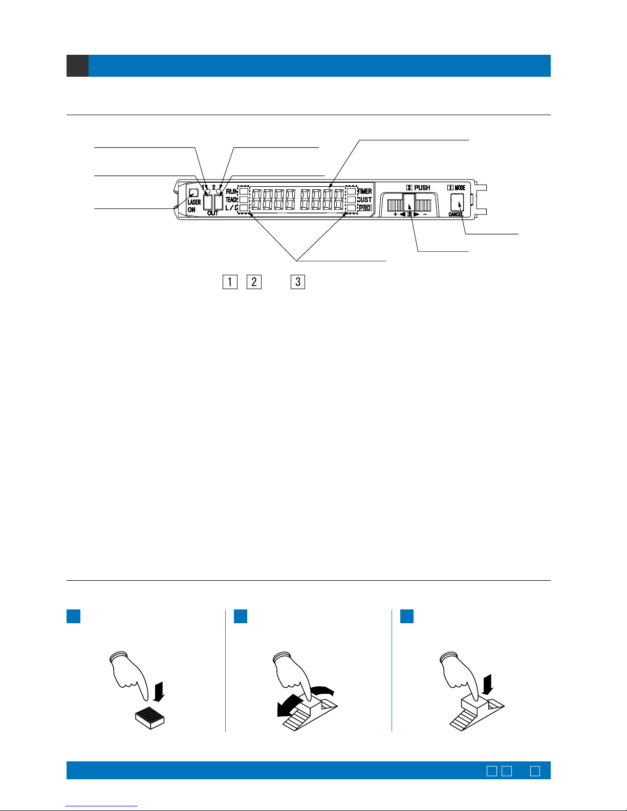
The use [MODE key] and [Jog switch] are utilized to configure various settings.
Press the [MODE key]
(mode selection / cancellation)
1
Turn the [Jog switch] in the ‘’ or
‘
’ direction (chooses setting for selection)
2
Press the [Jog switch]
(confirms the selected setting)
3
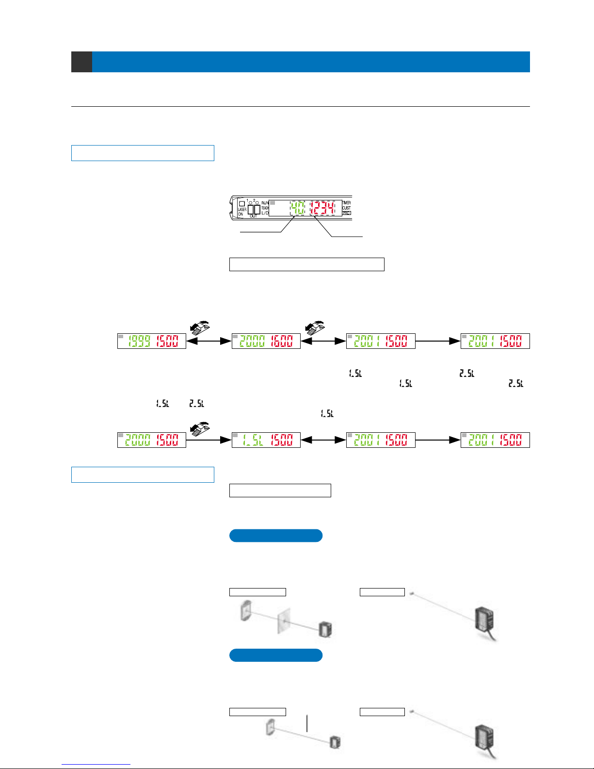
1Output 1 operation
indicator (Orange)
3Laser emission
indicator (Green)
2Select 1 indicator
(Yellow)
1Output 2 operation
indicator (Orange)
2Select 2 indicator
(Yellow)
Digital display (Green, Red)
4MODE indicators
6MODE key
5Jog switch
, and are in the correct order for selecting settings.
1
Output 1, 2 operation indicator (Orange)
……
2
Select 1, 2 indicator (Yellow)
……………
3
Laser emission indicator (Green)
………
4
MODE indicators
…………………………
5
Jog switch
…………………………………
6
MODE key
…………………………………
: Lights up during normal sensing operation.
:
When this indicator lights up, in normal mode, the ‘threshold
value’ can be set by utilizing either ‘2-level teaching’, ‘limit
teaching’ or ‘full-auto teaching’. In window comparator mode
and hysteresis mode, the ‘threshold value’ can be set by either
‘1-level teaching’, ‘2-level teaching’ or ‘3-level teaching’
whenever this indicator lights up. Span adjustment can be carried
out when using rising differential and trailing differential modes.
:
When this indicator lights up, the output operation setting can be done.
: When this indicator lights up, timer operation and timer period
setting can be done.
: When this indicator lights up, function is stored in the CUSTOM
mode, can be set.
: When this indicator lights up, further advanced functions, such
as the copying and memory functions, can be set.
Lights up when output 1 or output 2 is ON.
Lights up when output 1 or output 2 is selected.
Lights up when laser is emitted.
RUN (Green)
TEACH (Yellow)
L/D ON (Yellow)
TIMER (Yellow)
CUST (Yellow)
PRO (Yellow)
Moving this switch in the ‘
’ or ‘’ direction, allows different items to be viewed
for selection and pressing the switch then confirms the selected setting.
This key is used to select operating modes and to cancel settings while they are
being configured.
Selection and confirmation of settings are performed according to the order of the numbers, as shown on the amplifier:
1
, 2 and 3 .
1
P. 41l
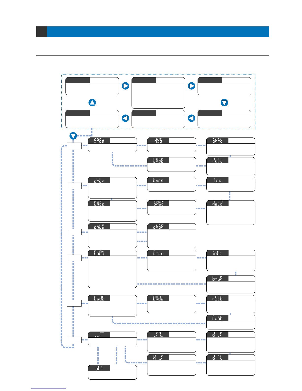
The amplifier of LS-400 series features and settings are generally classified into two main modes; the ‘NAVI’ mode
for items and settings that are frequently reconfigured, and the
‘
PRO’ mode that contains more detailed settings.
Diagram of Functions and Settings
2-1. Diagram of Functions and Settings
2
NAVI
mode
PRO
mode
mFor output 1
Refer to
p. 53l.
mFor
output 2
Refer to
p. 55.
PRO5
PRO4
PRO3
PRO2
PRO1
PRO6
This indicates normal sensing
operation. The threshold value
can be fine-adjusted as well.
Run
RUN
Allows various detailed settings to be
configured, such as optical communications,
save / load and other settings.
Pro
PRO
Shows stored settings for functions.
(Refer to p. 10.)
Custom
CUST
The threshold value can be set by utilizing
either ‘2-level / limit / full-auto teaching’. When
the sensor is in window comparator / hysteresis
mode, the threshold value can be set by either
‘1-level / 2-level / 3-level teaching’. When using
rising / trailing differential mode, ‘span
adjustment’ is carried out. (Refer to p. 11.)
Teaching
TEACH
Sets output operation either
Light-ON, or Dark-ON. (Refer to
p. 22.)
L-ON / D-ON
L/D ON
Configures operation and period
of the timer. (Refer to p. 23.)
Timer
TIMER
Switches among response
times. (Refer to p. 25.)
Response time change
Sets hysteresis. (Refer to p. 26.)
Hysteresis
Shifts the ‘threshold value’ by a
certain percentage increment in
‘limit teaching’. (Refer to p. 27.)
Shift
Selects laser emission to
execute or halt. (Refer to p. 29.)
Emission halt
Sets the digital display to turn
ON / OFF. (Refer to p. 34.)
ECO mode setting
Selects to display peak / bottom
values in the hold condition or
peak / bottom values in the digital
display refleshing condition.
(Refer to p. 35.)
Period hold
Saves current incident light
intensity. (Refer to p. 36.)
Sets the viewing orientation of the
digital display. (Refer to p. 33.)
Display turning
P. 30l
This selects whether the digital display
is fixed at digits, % or peak hold / bottom
hold display, or whether the display can
be selectable. (Refer to p. 32.)
Display switching
This simultaneously displays the saved incident
light intensity and the current incident light
intensity for checking things such as drops in
incident light intensity. (Refer to p. 37.)
Stored value comparison
P. 38l
Loads configuration setting from the data
bank. Select only one amplifier to load or all
amplifiers connected on the right side of the
main unit to load in a single step by using
optical communications. (Refer to p. 39.)
Data bank load
Saves configuration setting from the data
bank. Select only one amplifier to save or all
amplifiers connected on the right side of the
main unit to save in a single step by using
optical communications. (Refer to p. 40.)
Data bank save
Using optical communications,
configuration settings from the
main unit are copied to units
connected on the right side of
the main unit, in a single step.
(Except data bank load / save,
0-adjust function setting and
transmission change to permit /
not to permit.) (Refer to p. 42.)
Copy
mCable type only
mCable type only
Allows not to save the threshold
value, by teaching via external
input, in EEPROM. (Refer to p. 45.)
Backup setting
P. 46l
Allows basic configuration
information to be set in a single
step, by inputting a 8-digit code.
(Refer to p. 48.)
Coding
Forces the numerical value for
incident light intensity to ‘0’ on the
digital display. (Refer to p. 49.)
0-adjust setting
All settings, except for data
bank, revert to factory settings.
(Refer to p. 50.)
Reset
Sensing mode that cancels out
slight changes in light intensity so
that only sudden increases in
incident light intensity are sensed.
Rising differential mode
Judges if set two threshold values
are within the required range or not.
This can be selected in 1-level /
2-level / 3-level teaching.
Window comparator mode
Sets a threshold value for ON /
OFF operation.
Normal mode
Changes hysteresis to ignore
small change of incident light
intensity. This can be selected in
1-level / 2-level / 3-level teaching.
Hysteresis mode
Sensing mode that cancels out
slight changes in light intensity so
that only sudden decreases in
incident light intensity are sensed.
Trailing differential mode
Set to OFF when not using
output 2.
Output 2 OFF
Sets receiving light sensitivity
in 3 level (U-LG mode: 4-level).
(Refer to p. 28.)
M.G.S.
Using external input wire,
‘emission halt’, ‘full-auto
teaching’ or ‘limit teaching’ is
selected. (Refer to p. 44.)
Selects a function in CUSTOM
mode to display. (Refer to p. 51.)
CUSTOM mode display
Allows to ignore copy / load /
save operations in a single step
used by optical communications.
(Refer to p. 43.)
Transmission change
to permit / not to permit
External input
switch setting
()
()
P. 24l
P. 52l
Current value
storage
2
Be sure to set each item after selecting output 1 or output 2.
The items that can be set in output 1 and output 2 respectively are only 1 Threshold value, 2 Output
operation, 3 Timer operation and Timer period, and 4 Sensing mode (Output 2 can only be selected in
normal mode). The items other than those are common. (However, in case of setting with the direct code, a
combination of the output 1 / 2 can be set only for output operation. The items other than output operation are
valid only for the output 1.)
To cancel any operation, press the [MODE key]. If the [MODE key] is pressed once, the amplifier will return to
the previous settings status, immediately before the [Jog switch] was pressed and the selected setting has
been confirmed.
Others
3
Press the MODE
key once.
Example: When operating in PRO mode.
Press the Jog
switch once.
When changing the status of any setting, ensure that the selected setting is subsequently confirmed.
If confirmation is not performed, the new setting will not take effect.
Canceling operations
3-1. Precautions When Selecting Settings
Confirming settings
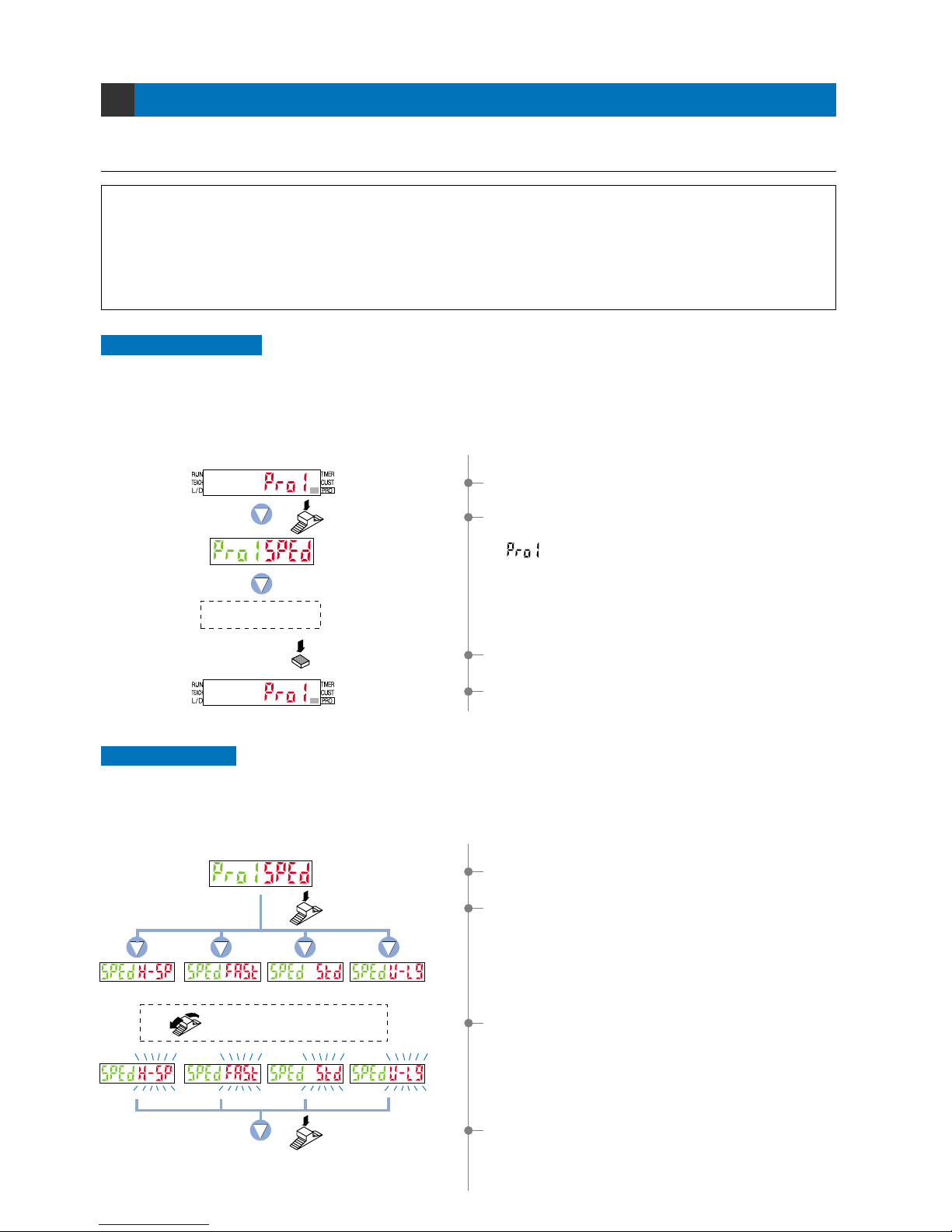
1Select ‘PRO mode’.
1Select ‘response time change’.
2If the [Jog switch] is pressed, the current mode (red) will be
displayed.
* The factory setting is ‘STD (standard)’.
3If the [Jog switch ] is turned, the digital display (red) will blink.
Select the desired mode.
3To cancel the ‘response time change’ operation, press the
[MODE key] once.
4
The display will return to the previous [PRO1 mode] selection
screen.
H-SP
(ultra high-speed)
Example: When setting response time change.
FAST
(high-speed)
Press the Jog switch.
Press the Jog switch.
The digital display will quickly blink to confirm the setting.
STD (standard) U-LG
(ultra long-range)
Select the desired mode
by turning the Jog switch.
To cancel
2If the [Jog switch] is pressed once, the amplifier enter the
‘response time change’ state.
[ move left side (Green)]
4If the [Jog switch] is pressed, the digital display (red) will
quickly blink, confirming the setting.
The digital display will not blink if the setting has not been
changed.
()
3
Note: Equipped with cable type only.
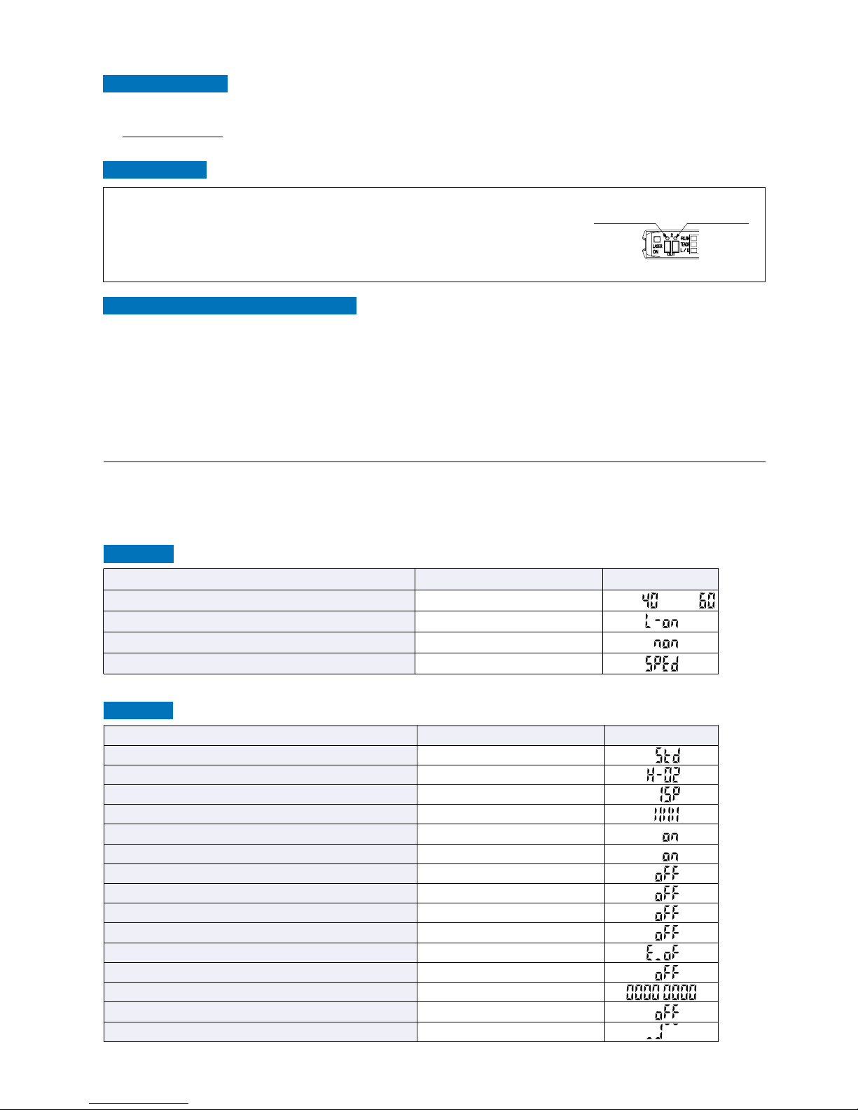
3-2. Factory Settings
NAVI mode
PRO mode
Item
Response time
Hysteresis
Amount of shift during limit teaching
M.G.S.
Emission halt
Display switching
Display turning
ECO mode
Period hold
Selection for transmission change to permit / not to permit
External input switch setting (Note)
Backup setting (Note)
Code setting
0-adjust setting
Output 1 / 2 sensing mode
Settings
STD (standard)
H-02 (standard)
15 %
Level 3
Laser emission ON
Incident light intensity display only
Digital display turning OFF
ECO OFF
Hold OFF
Lock OFF
Emission halt
OFF
00000000
OFF
Normal mode
Digital display
Item
Threshold value
Output operation
Timer operation
CUSTOM mode display
Settings
Output 1: 40, Output 2: 60
L-ONL-ON (Output 1 Output 2)
Without timer (Output 1Output 2)
Response time change
Output 1: , Output 2:
Digital display
Factory settings for the LS-400 series are indicated below:
If the amplifier is reset using the ‘9-4 Setting Reset Function’ from ‘PRO5 Mode’ on p. 50, the resulting settings
will be those indicated below:
Operation protection
You can use the ‘key lock function’ to protect these operations. (Refer to p. 56.)
Key lock function
This function can be used to prevent the operator from accidentally changing the sensor settings.
Automatic interference prevention function
To operate the automatic interference prevention function, you need to install the amplifiers so that they are
directed against each other and carry out optical communication.
The automatic interference prevention function allows up to four sensor heads to be installed so that they are
directed against each other.
(However, the automatic interference prevention function cannot be used in H-SP mode.)
Output switching
Set the sensing mode (PRO6) for output 1 to normal mode beforehand.
In modes other than normal mode, this is fixed at output 1.
Press the MODE key for more than 2 seconds when in NAVI mode. If Output 1
has been selected, the Select 1 indicator (yellow) lights up. If Output 2 is being
selected, the Select 2 indicator (yellow) lights up.
Select 1 indicator
(Yellow)
Select 2 indicator
(Yellow)
4
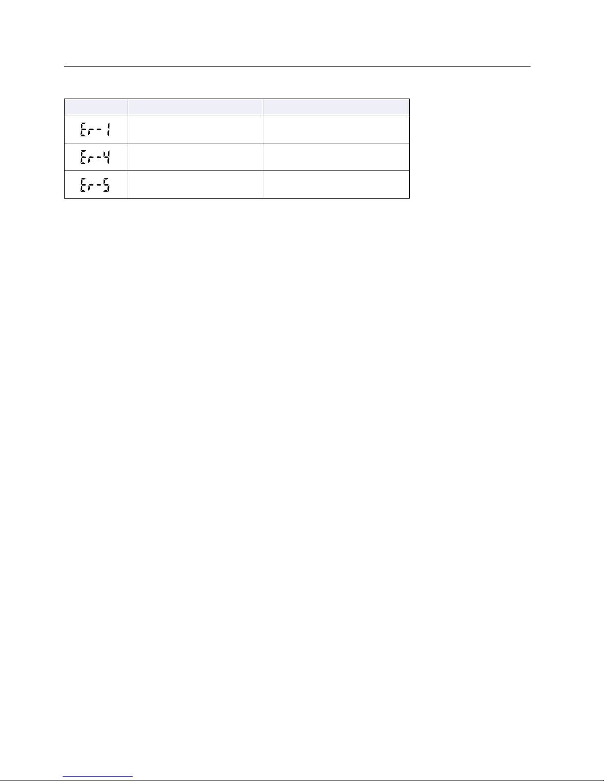
3-3. Error Display Indicator Readings
Digital display
Error description Measures
Turn off the power, then check
the load.
The load has short-circuited
and excess current is flowing.
Confirm that all amplifiers are
properly connected to each other.
Communication error has
occurred at time of connection.
Check the sensor head connection
status.
Disconnected sensor head
wire error.
In case of errors, attempt the following measures:
5
Settings for NAVI Mode
4-1. NAVI Mode Functions and Settings
4
RUN :
Normal Sensing Operation
TEACH : Teaching Mode
This indicates normal sensing operation. Threshold value (green) and incident light
intensity (red) are displayed in real time. Manual fine adjustment of the ‘threshold
value’ can be performed during normal sensing operation.
The ‘threshold value’ can be set with any of the 3 teaching methods, ‘2-level
teaching’, ‘limit teaching’ and ‘full-auto teaching’.
This mode sets the ‘threshold value’ by utilizing teaching.
When using normal mode
Turn the jog switch to either ‘’ (left) or ‘’ (right) to increase / decrease the
threshold value.
If there are no key operations after a certain period of time or if the MODE key is
pressed (to change to TEACH), the digital display (green) will blink and the setting
will be confirmed.
2-level teaching is a method of setting the threshold value by teaching the
amplifier two different status conditions - sensing object present and sensing
object absent.
The ‘threshold value’ is usually set using this method.
Refer to p. 11 ~ for setting procedure
P. 11
2-level Teaching
Retroreflective type
Retroreflective type
Reflective type
Reflective type
* The incident light intensity display can
display a maximum value of 4,000 in
H-SP (ultra high-speed) mode and
FAST (high-speed) mode. In STD
(standard) mode and U-LG (ultra longrange) mode, it can display up to a
maximum value of 9,999.
Confirmed
Confirmed
Automatic
AutomaticAutomatic
Turn to ''
Turn
* When you turn the jog switch to ‘’ or ‘’ in window comparator mode or hysteresis mode, the threshold
value will increase or decrease after the threshold value 1 ‘ ’ or the threshold value 2 ‘ ’ is displayed.
Each time the jog switch is pressed, the display switches between the ‘ ’ threshold value 1 and ‘ ’
threshold value 2.
After ‘ ’ or ‘ ’ is displayed, the respective threshold value will be displayed.
If you turn the jog switch to ‘
’ when the output 1 ‘ ’ is displayed, the following will be displayed.
Change
Turn
Threshold value
Incident light
intensity
Threshold value fine adjustment function
Teaches only the status condition in which no sensing object is within sensing
range (status in which incident light intensity is stable). This method is used to set
a ‘threshold value’ for conducting sensing in the presence of a background, or
when extremely small objects are to be detected.
P. 12
Limit Teaching
Very small object
In [NAVI mode], frequently changed settings can be easily configured.
Settings for four functions can be configured.
6
ON
A
1_SL
2_SL
B
C
0
OFF
P. 16 l
3-level Teaching
This carries out 3-level teaching (P-1, P-2, P-3) and sets the threshold value
(1_SL) between A and B and the threshold value (2_SL) between B and C as
shown in the diagram below.
After teaching, P-1, P-2 and P-3 are automatically assigned in ascending order to
‘A’, ‘B’, and ‘C’.
Time
Incident light
intensity
9,999
Output
(L-ON)
TEACH : Teaching Mode
Refer to p. 14 ~ for setting procedure
P. 14
1-level Teaching
This sets the shift value to any desired value, and sets the threshold values (1_SL,
2_SL) by means of 1-level teaching.
P. 15
2-level Teaching
This carries out 2-level teaching (P-1, P-2) and sets the threshold values (1_SL,
2_SL).
Time
ON
P-1
1_SL
P-2
2_SL
0
OFF
Time
Shift value
Shift value
ON
1_SL
2_SL
P-1
0
OFF
Incident light
intensity
9,999
Incident light
intensity
9,999
Output
(L-ON)
Output
(L-ON)
Output
(L-ON)
* In this figure, the incident light intensity of
P-1 is less than that of P-2.
P. 13
Full-auto Teaching
This method is used to set the threshold value while the sensing objects are still
moving on the production line, without stopping the production line.
When using window comparator mode
The ‘threshold value’ can be set with any of the 3 teaching methods (‘1-level
teaching’, ‘2-level teaching’ and ‘3-level teaching’). By setting two ‘threshold
values’, both ON and OFF can occur between the two threshold value levels.
Hysteresis
9,999
Incident light
intensity
ON
1_SL 2_SL
OFF
7
P. 18
1-level Teaching
This sets the shift value to any desired value, and sets the ON level / OFF level
(1_SL, 2_SL) by means of 1-level teaching (P-1).
Output
(L-ON)
Time
Time
Time
Shift value
Shift value
Incident light
intensity
9,999
Incident light
intensity
9,999
Incident light
intensity
9,999
Output
(L-ON)
Output
(L-ON)
Output
(L-ON)
* In this figure, the incident light intensity of
P-1 is less than that of P-2.
TEACH : Teaching Mode
Refer to p. 18 ~ for setting procedure
When using hysteresis mode
A
1_SL
2_SL
B
C
0
P-11_SL
P-2
2_SL
0
ON
1_SL
2_SL
P-1
0
OFF
ON
OFF
ON
OFF
9,999
Threshold value
ON
1_SL 2_SL
OFF
P. 19
2-level Teaching
This carries out 2-level teaching (P-1, P-2) and sets the ON level / OFF level
(1_SL, 2_SL).
P. 20 l
3-level Teaching
This carries out 3-level teaching (P-1, P-2, P-3) and sets the ON level / OFF level
(1_SL, 2_SL) between A and B as shown in the diagram below.
After teaching, P-1, P-2 and P-3 are automatically assigned in ascending order to
‘A’ ‘B’, and ‘C’.
This sets the ON / OFF levels with any of the 3 teaching methods (‘1-level
teaching’, ‘2-level teaching’ and ‘3-level teaching’) and sets the hysteresis.
By adjusting the hysteresis, the irregular sections of sensing objects with
irregularities are canceled out so that stable sensing is possible.
8
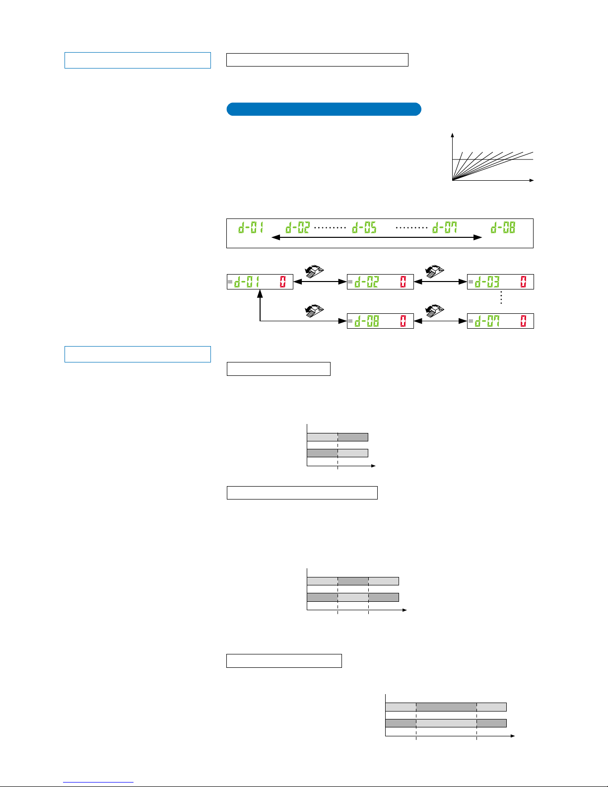
Span adjustment during differential mode
Time
Threshold
value
d-01
When setting differential mode in PRO mode, the maximum sensitivity (minimum
threshold value) is set.
If the response time is changed in differential
mode, the maximum sensitivity (minimum threshold
value) for that response time is set automatically.
Span adjustment for differential mode can be set
as follows in teaching mode. The threshold value
can be changed using the threshold value fine adjustment function. Refer to
‘threshold value fine adjustment function (P. 6)’ for details.
Changed intensity
Turn
Turn
Changed intensity
Changed intensity
Turn
Turn
Short span
(Sudden change)
Long span
(Gradual change)
(Note) (Note) (Note)
d-02 d-03 d-04 d-05 d-06 d-07 d-08
ONOFF OFF
OFFON ON
0
Threshold value
Threshold
value 1
(1_SL)
Threshold
value 2
(2_SL)
Incident light
intensity
Incident light
intensity
9,999
ONOFF
OFFON
Output
operation
L-ON
D-ON
Output
operation
L-ON
D-ON
* The factory setting is ‘L-ON (Light-ON)’.
0 9,999
L/D ON :
Output Operation Setting Mode
Refer to p. 22 for setting procedure
This mode allows the selection of output operation from either Light-ON, or Dark-ON.
* Products manufactured up until June 2004 (~ Lot No.: 4F□) are set in 5 steps (d-01 to d-05).
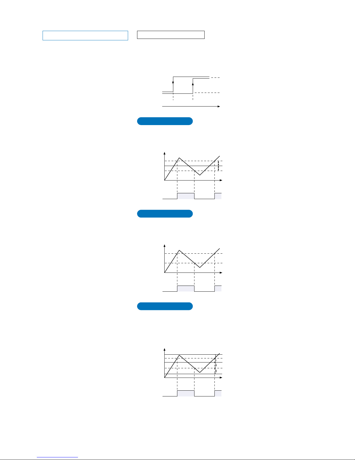
When using differential (rising or trailing) mode
For L-ON, the output turns ON when the incident light intensity is greater than the
ON level (2_SL), and the output turns OFF when the incident light intensity is less
than the OFF level (2_SL).
For D-ON, the output turns OFF
when the incident light intensity
is greater than the OFF level
(2_SL), and the output turns ON
when the incident light intensity
is less than the ON level (1_SL).
When using hysteresis mode
When using normal mode
When using window comparator mode
Incident
light
intensity
Changed intensity
Changed intensity
ON level or OFF level
(2_SL)
OFF level or ON level
(1_SL)
ON or OFFOFF ON
OFF or ONON OFF
Output
operation
L-ON
D-ON
0 9,999
Incident
light
intensity
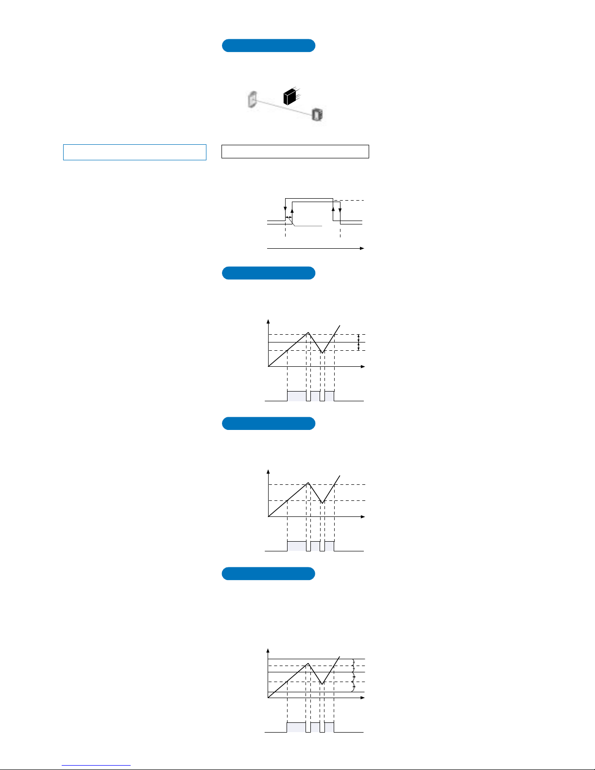
Only sudden changes in the light intensity are sensed, so that objects such as
glass edges can also be sensed with stability.
When set to ‘L-ON’, the output will be ON if the incident light intensity becomes
greater than the ‘threshold value’.
When set to ‘D-ON’, the output will be ON if the incident light intensity becomes
less than the ‘threshold value’.
When set to ‘L-ON’, if the incident light intensity is between the two ‘threshold
value’ levels, the output will be ON. If the incident light intensity is outside of the
two threshold value levels, the output will be OFF.
When set to ‘D-ON’, if the incident light intensity is between the two ‘threshold
value’ levels, the output will be OFF. If the incident light intensity is outside of the
two threshold value levels, the output will be ON.
TEACH : Teaching Mode
9
This sets timer operation and the timer period. The setting can be selected from
Without timer / OFF-delay / ON-delay / ONE-SHOT timer. The factory setting is
‘Without timer’.
Timer period: Approx. 1 to 9,999 ms
* When using rising / trailing differential mode, the timer is set automatically to
ONE-SHOT timer.
* For products manufactured up until June 2004 (~ Lot No.: 4F□) timer modes
other than ONE-SHOT timer cannot be used in differential modes.
When using rising differential mode
Output
operation
L-ON
D-ON
Time
ON
Output
operation
L-ON
D-ON
ON
TT
OFF
When using trailing differential mode
Time
ON
OFF
OFF
ON
OFF
TT
Incident
light
intensity
Incident
light
intensity
* The output time ‘T’ can be set by changing
the timer period in timer setting mode
(initial value: 10 ms).
* The output time ‘T’ can be set by changing
the timer period in timer setting mode
(initial value: 10 ms).
This is used to make detailed settings for functions selected in PRO5 mode. Out of
the response time change function, M.G.S. function, emission halt function, data
bank function and code setting function, one of these functions selected in PRO5
mode can be set in detail. Refer to the pages for each function for details on the
setting methods.
CUST : CUSTOM Mode
TIMER :
Timer Setting Mode
Refer to p. 23 for setting procedure
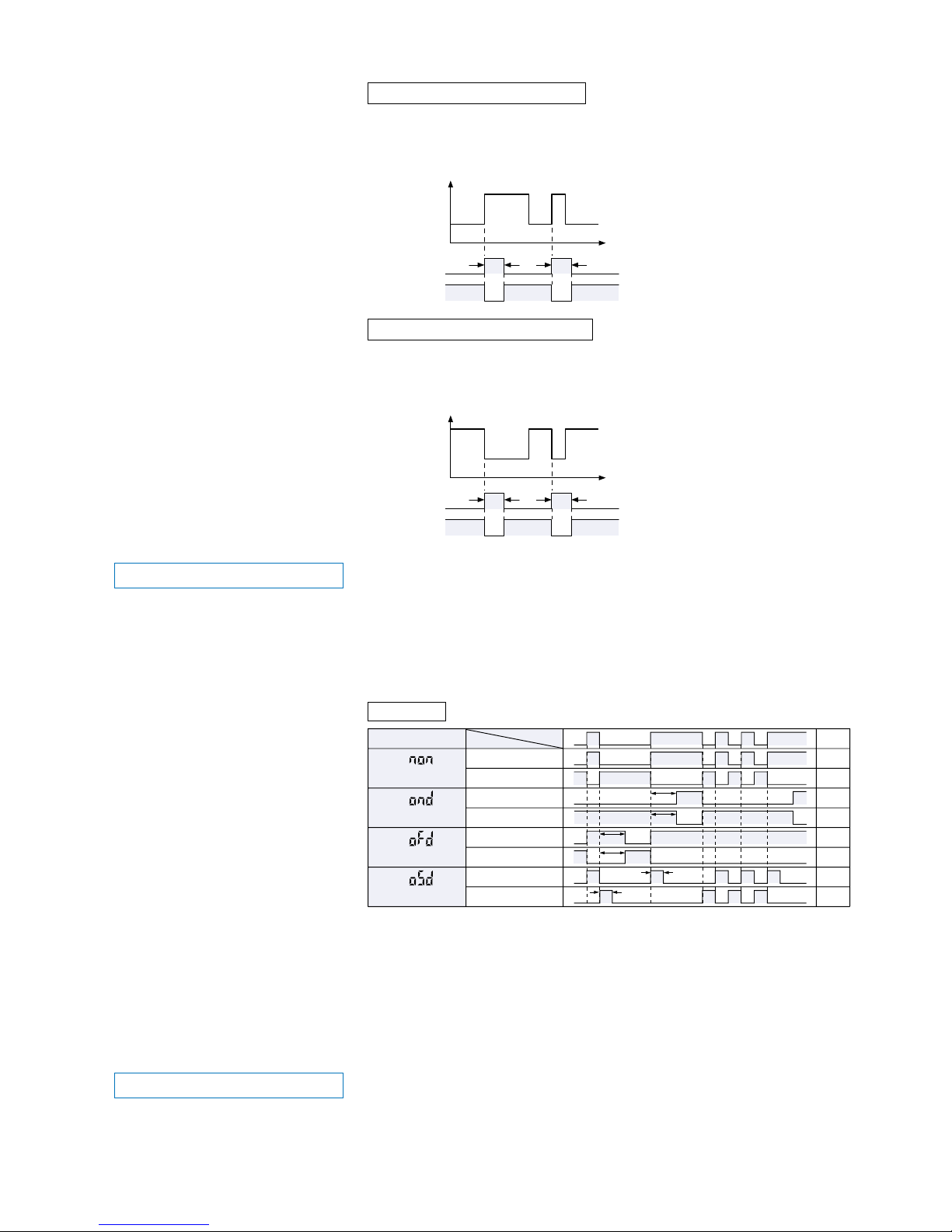
Sensing condition
Beam-received
Beam-interrupted
Output operation
Timer operation
ON
OFF
ON
OFF
ON
OFF
ON
OFF
ON
OFF
ON
OFF
ON
OFF
ON
OFF
(Without Timer)
Light-ON
(ON-delay)
Dark-ON
Light-ON
Dark-ON
Light-ON
Dark-ON
Light-ON
Dark-ON
(OFF-delay)
(ONE-SHOT)
T1
T1
T1
T1
T1
T1
Timer period T1Approx. 1 ms to 9,999 ms
* OFF-delay:
ON-delay:
ONE-SHOT:
Extends the output signal for a fixed period of time.
This function is useful if the output signal is so short that the connected device cannot
respond.
Neglects short output signals.
As only long signals are extracted, this function is useful for detecting if a line is clogged, or
for sensing only objects taking a long time to travel.
Outputs a fixed width signal upon sensing.
This function is useful when the input specifications of the connected device require a
signal of fixed width. Of course, it is also useful for extending a short width signal to a
desired width.
Time chart
For L-ON, output is ON for a constant period of time when the incident light
intensity is rising.
For D-ON, output is OFF for a constant period of time when the incident light
intensity is rising.
For L-ON, output is ON for a constant period of time when the incident light
intensity is trailing.
For D-ON, output is OFF for a constant period of time when the incident light
intensity trailing.
10
4-2. Teaching Mode (when using normal mode)
2-level teaching is a method of setting the ‘threshold value’ by teaching the amplifier two different
status conditions - sensing object present and sensing object absent. The ‘threshold value’ is
usually set using this method.
The ‘threshold value’ can be set by utilizing three kinds of teaching, whichever ‘2-level teaching’, ‘limit teaching’ or
‘full-auto teaching’.
* Select output 1 and output 2 and the sensing mode beforehand.
Place a sensor head within sensing range.
Press the
MODE key once.
Status condition - sensing object is present
Press the
Jog switch.
Press the
Jog switch.
()
Status condition - sensing object is absent
Difference between incident light
intensities is not great enough.
Stable sensing
Press the
MODE key 5 times.
2-level Teaching
1Select ‘TEACH mode’ by pressing the [MODE key] once.
2Press the [Jog switch] when in the status condition of -
sensing object is present.
4Press the [Jog switch] when in the status condition of -
sensing object is absent.
7The incident light intensity (red) will again be displayed,
indicating that configuration is now complete.
8By pressing the [MODE key] 5 times, the amplifier will return
to ‘RUN mode’ (normal sensing operation).
5The digital display will again blink the incident light intensity
reading (red) and the ‘threshold value’ will be set to a value
midway between the incident light intensities when the
sensing object is present and when it is absent. The blinking
MODE indicator / TEACH will stop blinking and continuously
light up.
* Fine adjustment of the ‘threshold value’ can be performed
in the RUN mode.
6The set ‘threshold value’ (green) will indicate and the
sensing stability status will be displayed.
• When stable sensing can be performed
n The digital display will blink the word ‘ ’ (red).
• When stable sensing cannot be performed
n The digital display will blink the word ‘ ’ (red).
3The digital display will indicate the incident light intensity
reading (green), then the MODE indicator / TEACH (yellow)
will blink.
This indicates that the second point item is now ready for
input.
11
Place a sensor head within sensing range.
Press the
MODE key once.
Press the
Jog switch.
Status condition - sensing object is absent
Press the
MODE key 5 times.
Shifting can be performed. Shifting cannot be performed.
Teaches only the status condition in which no sensing object is within sensing range (status in
which incident light intensity is stable). This method is used to set a ‘threshold value’ for
conducting sensing in the presence of a background, or when extremely small objects are to be
detected.
Limit Teaching
The digital display
will scroll.
Turn the Jog switch
in the ‘
’ or ‘’
direction.
1Select ‘TEACH mode’ by pressing the [MODE key] once.
2Press the [Jog switch] when in the status condition of -
sensing object is absent.
3The digital display will indicate the incident light intensity
reading (green), then the MODE indicator / TEACH (yellow)
will blink.
4Turn the [Jog switch] in either the ‘’ or ‘’ direction.
When using retroreflective type sensor head
When using reflective type sensor head
• If the switch is turned toward the ‘
’ direction, the digital
display will scroll from the left to the right and the threshold
value will be shifted down by approx. 15 %, to a value lower
than the incident light intensity displayed (high sensitivity).
• If the switch is turned toward the ‘
’ direction, the digital
display will scroll from the right to the left and the threshold
value will be shifted up by approx. 15 %, to a value higher
than the incident light intensity displayed (low sensitivity).
*
The initial factory-set value of the shift amount is approx. 15 %.
The shift amount can be changed by utilizing the ‘5-4. Shift
Function’ from ‘PRO1 Mode’, described on p. 27. (The
percentage adjustment is variable from approx. 5 % to 200 %,
in increments of 1 %.)
6
The incident light intensity (red) will again be displayed,
indicating that configuration is now complete.
7By pressing the [MODE key] 5 times, the amplifier will return
to ‘RUN mode’ (normal sensing operation).
5The set ‘threshold value’ (green) will indicate and the
judgement on whether the shift amount can be shifted or not
will be displayed.
• When the shifting can be performed
n The digital display will blink the word ‘ ’.
• When the shift amount cannot be changed because the
setting exceeds the upper or lower display limit (the value
is reset to within the upper and lower limits)
n The digital display will blink the word ‘ ’.
12
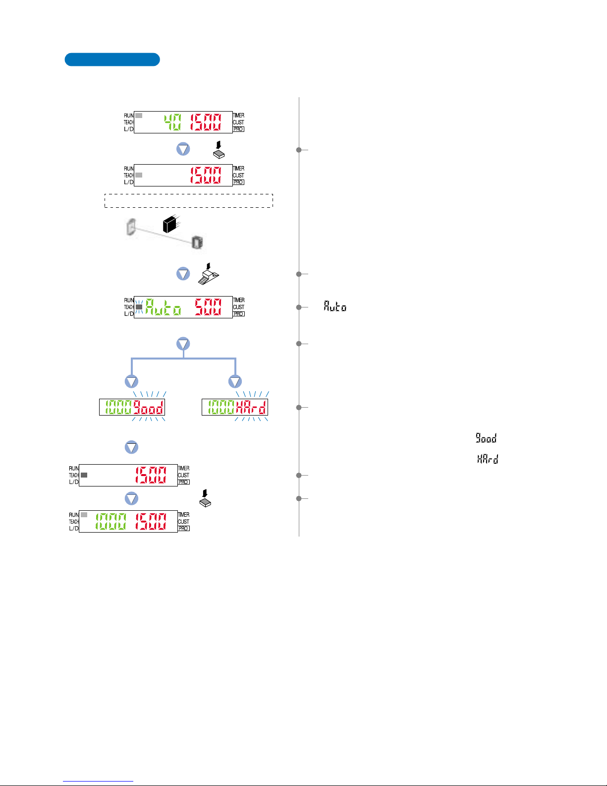
Full-auto teaching is used to set the threshould value while the sensing objects are still moving on
the production line, without stopping the production line.
Full-Auto Teaching
Place a sensor head within sensing range.
Press the
MODE key once.
Hold down the
Jog switch.
Status condition-moving the production line
Difference between incident light
intensities is not great enough.
Stable sensing
Press the
MODE key 5 times.
1Select ‘TEACH mode’ by pressing the [MODE key] once.
2Hold down the [Jog switch] for 0.5 sec. or more when in the
status condition when the object moving on the production
line.
4Incident light intensity (red) will blink on the digital display,
and the ‘threshold value’ will be set to a value midway
between the incident light intensities when the sensing
object is present and when it is absent.
5The set ‘threshold value’ (green) will indicate and the
judgement on the stability of sensing will be displayed.
• When stable sensing can be performed
n The digital display will blink the word ‘ ’ (red).
• When stable sensing cannot be performed
n The digital display will blink the word ‘ ’ (red).
3‘ ’ (green) is displayed on the digital display, then the
MODE indicator / TEACH (yellow) will blink. Release the jog
switch when the object has passed.
7By pressing the [MODE key] 5 times , the amplifer will return
to ‘RUN mode’ (nomal sensing operation).
6The incident light intensity (red) will again be displayed,
indicating that configuration is now complete.
13
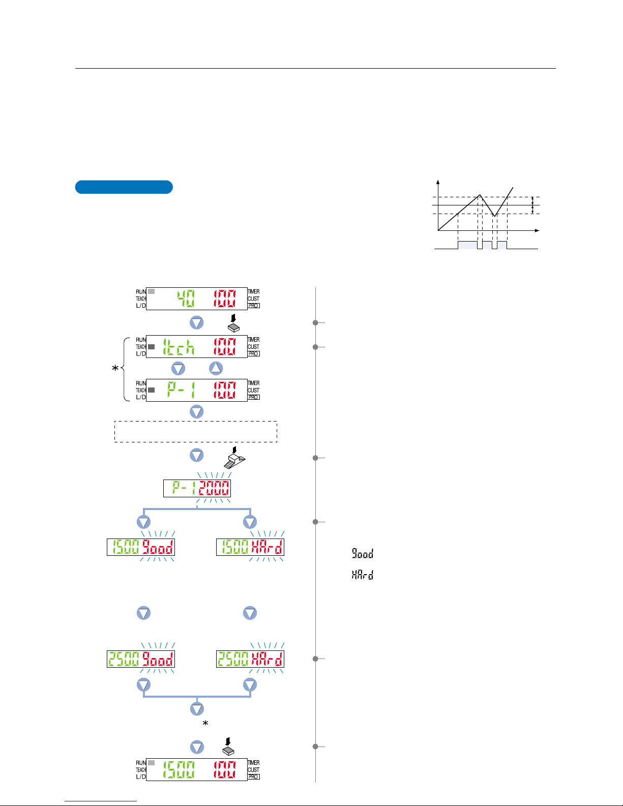
This is the method of setting the threshold values
(1_SL, 2_SL) by one level (P-1) teaching. The shift
value can be set as desired.
* The shift value units can be selected from two units:
‘digit’ or ‘%’.
* The shift value of the factory setting is set to ‘100’ of
‘digit’ units.
To set the shift value, refer to the section entitled ‘10-2.
Output 1 Sensing Mode Settings’ from ‘PRO6 Mode’
on p. 53.
4-3. Teaching Mode (when using window comparator mode)
1-level Teaching
Time
Shift value
Shift value
ON
1_SL
2_SL
P-1
0
OFF
Incident light
intensity
9,999
Output
(L-ON)
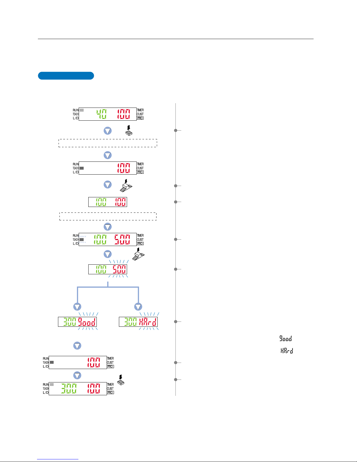
The ‘threshold value’ can be set using ‘1-level teaching’, ‘2-level teaching’ or ‘3-level teaching’. In window
comparator mode, teaching is performed using the teaching methods described in the section entitled ‘10-2.
Output 1 Sensing Mode Settings’ from ‘PRO6 Mode’ on p. 53.
Change the teaching method using ‘10-2. Output 1 Sensing Mode Settings’ from ‘PRO6 Mode’ on p. 53
beforehand.
* Window comparator mode can be set done for output 1 only.
* The factory setting is ‘1-level teaching’.
Press the
MODE key once.
Blinking by turns.
The status condition when a sensing object is
present that can be used as a standard.
Upper limit value 2_SL
Press the
Jog switch.
Incident light
intensity for P-1.
Lower limit value 1_SL
The symbol ‘ ’ will be
displayed repeatedly.
Press the
MODE key 5 times.
If the shift value has
been set to 500.
Upper and lower limits have
not been correctly set.
1Select ‘TEACH mode’ by pressing the [MODE key] once.
2The current teaching method (green) and incident light
intensity (red) will be displayed and the amplifier will enter
the ‘P-1’ setting state.
3If the [Jog switch] is pressed while in the status condition
when a sensing object is present that can be used as a
standard, then the display will blink the incident light intensity
reading (red).
6By pressing the [MODE key] 5 times, the amplifier will return
to ‘RUN mode’ (normal sensing operation).
‘Lower limit value 1_SL’ (green) and incident light intensity
(red) will be displayed.
5Then the setting for ‘upper limit value 2_SL’ (green) will be
displayed.
4The display will indicate whether the upper and lower
threshold value limits have been correctly set and the setting
for ‘lower limit value 1_SL’ (green) will be displayed.
• If ‘ ’ (red) is blinking…the upper and lower limits have
been set correctly.
• If ‘ ’ (red) is blinking…the upper and lower limits have
not been set correctly.
* The shift value of the factory setting is set to ‘100’ of ‘digit’
units.
To set the shift value, refer to the section entitled ‘10-2.
Output 1 Sensing Mode Settings’ from ‘PRO6 Mode’ on
p. 53.
14
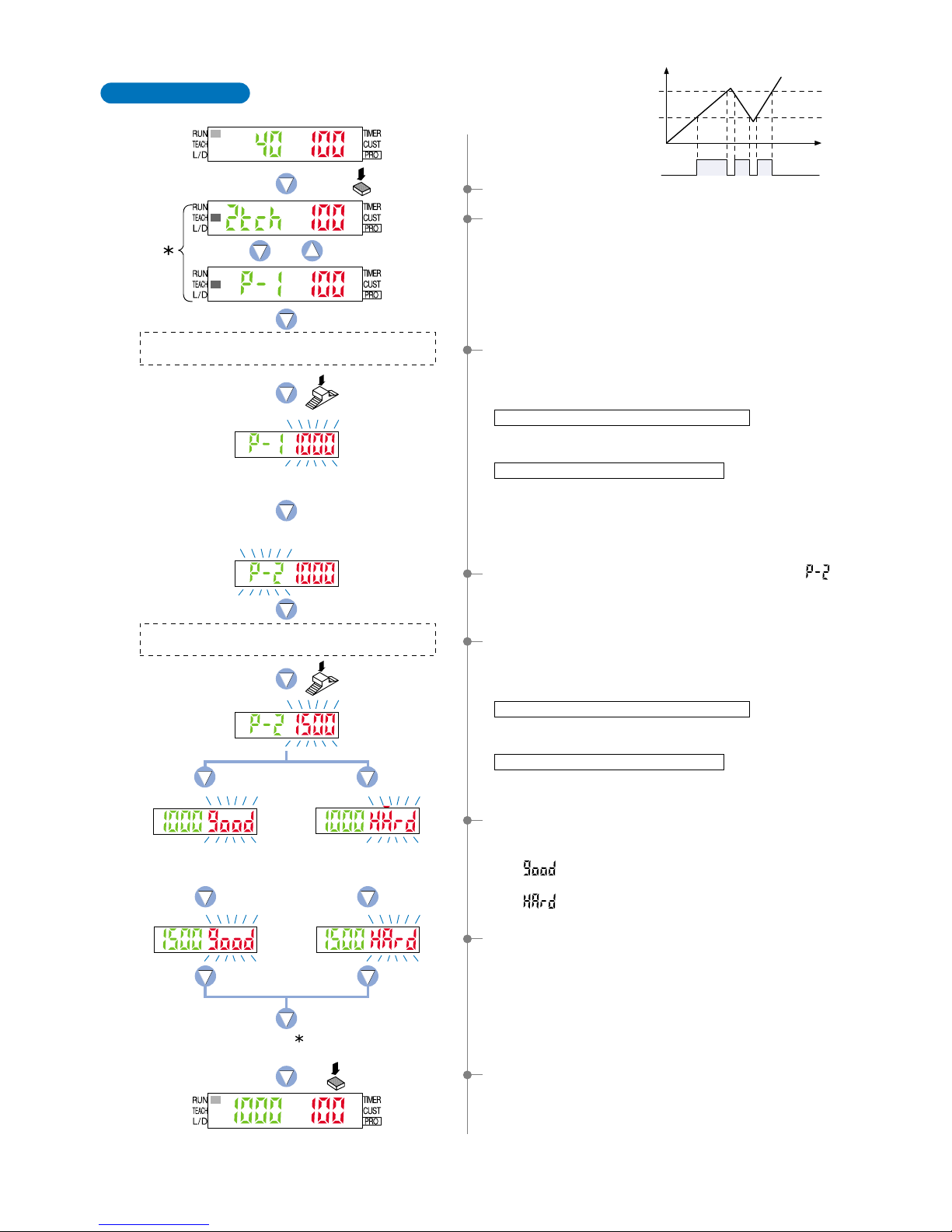
2-level Teaching
This is a method of setting the threshold values
(1_SL, 2_SL) by two levels (P-1, P-2) teaching.
Time
ON
P-1
1_SL
P-2
2_SL
0
OFF
Incident light intensity
9,999
Output
(L-ON)
Press the
MODE key once.
Blinking by turns.
Press the
Jog switch.
Press the
Jog switch.
Incident light
intensity for P-1.
Incident light
intensity for P-2.
Upper limit value 2_SL
Lower limit value 1_SL
The symbol ‘
’ will be
displayed repeatedly.
Press the
MODE key 5 times.
Upper and lower limits have
not been correctly set.
The status condition when a sensing object is present
that can be used as a standard for the lower limit.
The status condition when a sensing object is present
that can be used as a standard for the upper limit.
2The current teaching method (green) and incident light
intensity (red) will be displayed and the amplifier will enter
the ‘P-1’ setting state.
4The amplifier has entered the ‘P-2’ setting state and ‘ ’
(green) will blink.
7Then the setting for ‘upper limit value 2_SL’ (green) will be
displayed.
8By pressing the [MODE key] 5 times, the amplifier will return
to ‘RUN mode’ (normal sensing operation).
‘Lower limit value 1_SL’ (green) and incident light intensity
(red) will be displayed.
6The display will indicate whether the upper and lower limits
have been correctly set and the setting for ‘lower limit value
1_SL’ (green) will be displayed.
• If ‘ ’ (red) is blinking…the upper and lower limits have
been set correctly.
• If ‘ ’ (red) is blinking…the upper and lower limits have
not been set correctly.
5If the [Jog switch] is pressed while in the status condition
when a sensing object is present that can be used as a
standard for the upper limit, then the display will blink the
incident light intensity reading (red).
When using retroreflective type sensor head
• Press the [Jog switch] for the sensing object that has the
least amount of interrupted light.
When using reflective type sensor head
• Press the [Jog switch] for the sensing object with the
greatest incident light intensity.
3If the [Jog switch] is pressed while in the status condition
when a sensing object is present that can be used as a
standard for the lower limit, then the display will blink and
indicate the incident light intensity reading (red).
When using retroreflective type sensor head
• Press the [Jog switch] for the sensing object that has the
greatest amount of interrupted light.
When using reflective type sensor head
• Press the [Jog switch] for the sensing object with the lowest
intensity of incident light.
Note) Even if procedures 3 and 5 are reversed, teaching for a
sensing object with low intensity incident light will
automatically cause the setting of ‘lower limit value 1_SL’.
1Select ‘TEACH mode’ by pressing the [MODE key] once.
15
ON
A
1_SL
2_SL
B
C
0
OFF
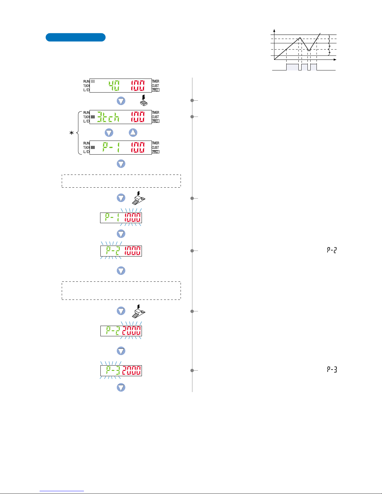
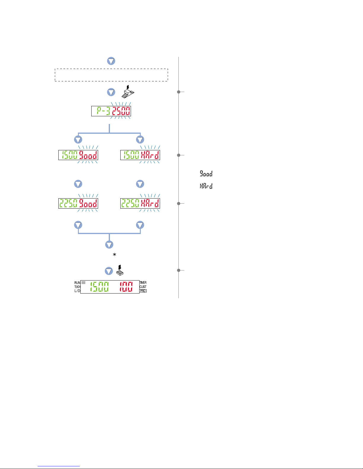
3-level Teaching
This is a method of setting the threshold range by
three levels (P-1, P-2, P-3) teaching and set the
threshold values at the middle of ‘A’ and ‘B’ (1_SL) and
‘B’ and ‘C’ (2_SL).
After teaching, P-1, P-2 and P-3 are automatically
assigned in ascending order to ‘A’, ‘B’, and ‘C’.
Time
Output
(L-ON)
Press the
MODE key once.
Blinking by turns.
Press the
Jog switch.
Press the
Jog switch.
Incident light
intensity for P-1.
Incident light
intensity for P-2.
The status condition when sensing object ‘A’ is present
that has the lowest intensity of incident light.
The status condition when sensing object ‘B’ is present
that has an incident light intensity in between that of
sensing object ‘A’ and sensing object ‘C’.
Incident light intensity
9,999
1Select ‘TEACH mode’ by pressing the [MODE key] once.
4The amplifier has entered the ‘P-2’ setting state and ‘ ’
(green) will blink.
6
The
amplifier
has entered the ‘P-3’ setting state and ‘ ’
(green) will blink.
2The current teaching method (green) and incident light
intensity (red) will be displayed and the amplifier will enter
the ‘P-1’ settting state.
3If the [Jog switch] is pressed while in the status condition
when sensing object ‘A’ is present that has the lowest
intensity of incident light, then the display will blink the
incident light intensity reading (red).
5If the [Jog switch] is pressed while in the status condition
when sensing object ‘B’ is present that has an incident light
intensity in between that of sensing object ‘A’ and sensing
object ‘C’, the display will blink the incident light intensity
reading (red).
16
The status condition when sensing object ‘C’ is present
that has the greatest intensity of incident light.
Press the
Jog switch.
Incident light
intensity for P-3.
Upper limit value 2_SL
Lower limit value 1_SL
Upper and lower limits have
not been correctly set.
The symbol ‘
’ will be
displayed repeatedly.
Press the
MODE key 5 times.
7If the [Jog switch] is pressed while in the status condition
when sensing object ‘C’ is present that has the greatest
intensity of incident light, the display will blink the incident
light intensity reading (red).
8The display will indicate whether the upper and lower limits
have been correctly set and the setting for ‘lower limit value
1_SL’ (green) will be displayed.
• If ‘ ’ (red) is blinking…the upper and lower limits have
been set correctly.
• If ‘ ’ (red) is blinking…the upper and lower limits have
not been set correctly.
9Then the setting for ‘upper limit value 2_SL’ (green) will be
displayed.
0By pressing the [MODE key] 5 times, the amplifier will return
to ‘RUN mode’ (normal sensing operation).
‘Lower limit value 1_SL’ (green) and incident light intensity
(red) will be displayed.
17

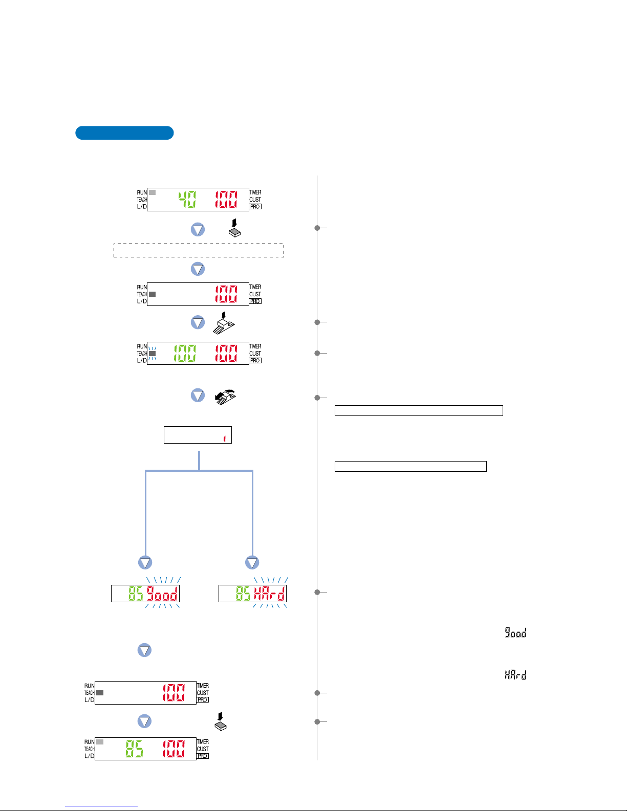
This is the method of setting the ON Level / OFF Level
(1_SL, 2_SL) by one level (P-1) teaching. The shift
value can be set as desired.
* The shift value units can be selected from two units:
‘digit’ or ‘%’.
* The shift value of the factory setting is set to ‘100’ of
‘digit’ units.
To set the shift value, refer to the section entitled
‘10-2. Output 1 Sensing Mode Settings’ from
‘PRO6 Mode’ on p. 53.
4-4. Teaching Mode (when using hysteresis mode)
1-level Teaching
Time
Shift value
Shift value
1_SL
2_SL
P-1
Incident light
intensity
9,999
Output
(L-ON)
The ‘ON Level / OFF Level’ can be set using ‘1-level teaching’, ‘2-level teaching’ or ‘3-level teaching’. In
hysteresis mode, teaching is performed using the teaching methods described in the section entitled ‘10-2.
Output 1 Sensing Mode Settings’ from ‘PRO6 Mode’ on p. 53
Change the teaching method using ‘10-2. Output 1 Sensing Mode Settings’ from ‘PRO6 Mode’ on p. 53
beforehand.
* Hysteresis mode can be set for output 1 only.
* The factory setting is ‘1-level teaching’.
OFF or ON level 1_SL
ON or OFF level 2_SL
Press the
MODE key once.
Blinking by turns.
The status condition as a standard.
Press the
Jog switch.
Incident light
intensity for P-1.
The symbol ‘
’ will be
displayed repeatedly.
Press the
MODE key 5 times.
If the shift value has
been set to 200.
ON or OFF level have
not been correctly set.
ON
0
OFF
1Select ‘TEACH mode’ by pressing the [MODE key] once.
2The current teaching method (green) and incident light
intensity (red) will be displayed and the amplifier will enter
the ‘P-1’ setting state.
3If the [Jog switch] is pressed while in the status condition as
a standard, then the display will blink the incident light
intensity reading (red).
5Then the setting for ‘ON or OFF level 2_SL’ (green) will be
displayed.
6By pressing the [MODE key] 5 times, the amplifier will return
to ‘RUN mode’ (normal sensing operation).
‘OFF or ON level 1_SL’ (green) and incident light intensity
(red) will be displayed.
4The display will indicate whether the ON and OFF level have
been correctly set and the setting for ‘OFF or ON level 1_SL’
(green) will be displayed.
• If ‘ ’ (red) is blinking…the ON and OFF level have
been set correctly.
• If ‘ ’ (red) is blinking…the ON and OFF level have not
been set correctly.
* The shift value of the factory setting is set to ‘100’ of ‘digit’
units.
To set the shift value, refer to the section entitled ‘
10-2.
Output 1 Sensing Mode Settings
’ from ‘PRO6 Mode’
on p. 53.
18

2-level Teaching
This is a method of setting the ON level / OFF
level (1_SL, 2_SL) by two levels (P-1, P-2)
teaching.
Time
ON
P-11_SL
P-2
2_SL
OFF
Incident light intensity
9,999
Output
(L-ON)
0
Press the
MODE key once.
Blinking by turns.
The status condition as a standard for the OFF or ON level.
The status condition as a standard for the ON or OFF level.
Incident light
intensity for P-1.
Incident light
intensity for P-2.
Press the
Jog switch.
Press the
Jog switch.
OFF or ON level 1_SL
ON or OFF level 2_SL
Upper and lower limits have
not been correctly set.
The symbol ‘ ’ will be
displayed repeatedly.
Press the
MODE key 5 times.
1Select ‘TEACH mode’ by pressing the [MODE key] once.
2The current teaching method (green) and incident light
intensity (red) will be displayed and the amplifier will enter
the ‘P-1’ setting state.
4
The amplifier has entered the ‘P-2’ setting state and ‘ ’
(green) will blink.
7Then the setting for ‘ON or OFF level 2_SL’ (green) will be
displayed.
8By pressing the [MODE key] 5 times, the amplifier will return
to ‘RUN mode’ (normal sensing operation).
‘OFF or ON level 1_SL’ (green) and incident light intensity
(red) will be displayed.
6The display will indicate whether the ON and OFF level have
been correctly set and the setting for ‘OFF or ON level 1_SL’
(green) will be displayed.
• If ‘ ’ (red) is blinking…the ON and OFF level have
been set correctly.
• If ‘ ’ (red) is blinking…the ON and OFF level have not
been set correctly.
5If the [Jog switch] is pressed while in the status condition as
a standard for the ON level or OFF level, then the display will
blink the incident light intensity reading (red).
When using retroreflective type sensor head
• Press the [Jog switch] when the interrupted light is the least
amount.
When using reflective type sensor head
• Press the [Jog switch] when the incident light is the greatest
intensity.
3If the [Jog switch] is pressed while in the status condition as
a standard for the OFF level or ON level, then the display will
blink the incident light intensity reading (red).
When using retroreflective type sensor head
• Press the [Jog switch] when the interrupted light is the
greatest amount.
When using reflective type sensor head
• Press the [Jog switch] when the incident light is the lowest
intensity.
Note)
Even if procedures 3 and 5 are reversed, teaching in
condition of low intensity of incident light will automatically
cause the setting of ‘OFF level or ON level 1_SL’.
19

3-level Teaching
This is a method of setting the ON and OFF range by
three levels (P-1, P-2, P-3) teaching and set the OFF
level or ON level at the middle of ‘A’ and ‘B’ (1_SL) and
set the ON level or OFF level at the middle of ‘B’ and
‘C’ (2_SL).
After teaching, P-1, P-2 and P-3 are automatically
assigned in ascending order to ‘A’, ‘B’, and ‘C’.
Time
A
1_SL
2_SL
B
C
0
ON
OFF
Incident light intensity
9,999
Output
(L-ON)
Press the
MODE key once.
Blinking by turns.
Press the
Jog switch.
Incident light
intensity for P-1.
Press the
Jog switch.
Incident light
intensity for P-2.
The status condition (A) when incident light
is the lowest intensity.
The status condition (B) when the incident light
intensity is between lowest and greatest.
1Select ‘TEACH mode’ by pressing the [MODE key] once.
2The current teaching method (green) and incident light
intensity (red) will be displayed and the amplifier will enter
the ‘P-1’ setting state.
3If the [Jog switch] is pressed while in the status condition (A)
when the incident light is the lowest intensity, then the
display will blink the incident light intensity reading (red).
4The amplifier has entered the ‘P-2’ setting state and ‘ ’
(green) will blink.
5If the [Jog switch] is pressed while in the status condition (B)
when the incident light intensity is between lowest and
greatest, the display will blink the incident light intensity
reading (red).
20

Incident light
intensity for P-3.
Press the
Jog switch.
OFF or ON level 1_SL
ON or OFF level 2_SL
The symbol ‘
’ will be
displayed repeatedly.
Press the
MODE key 5 times.
Upper and lower limits have
not been correctly set.
The status condition (C) when incident light
is the greatest intensity.
6The amplifier has entered the ‘P-3’ setting state and ‘ ’
(green) will blink.
7If the [Jog switch] is pressed while in the status condition (C)
when the incident light is the greatest intensity, then the
display will blink and indicate the incident light intensity
reading (red).
9Then the setting for ‘ON or OFF level 2_SL’ (green) will be
displayed.
0By pressing the [MODE key] 5 times, the amplifier will return
to ‘RUN mode’ (normal sensing operation).
‘OFF or ON level 1_SL’ (green) and incident light intensity
(red) will be displayed.
8The display will indicate whether the ON and OFF level have
been correctly set and the setting for ‘OFF or ON level 1_SL’
(green) will be displayed.
• If ‘ ’ (red) is blinking…the ON and OFF level have
been set correctly.
• If ‘ ’ (red) is blinking…the ON and OFF level have not
been set correctly.
21

ON
TT
OFF
ON
TT
OFF
TT
TT
ON
OFF
ON
OFF
ON or OFFOFF
OFF
OFF or ONON
ON
4-5. Output Operation Setting Mode
This mode allows the selection of output operation
from either L-ON (Light-ON), or D-ON (Dark-ON).
* Select the output 1 or output 2 beforehand.
ONOFF
OFFON
Threshold
value
Incident light
intensity
Incident light
intensity
Incident light
intensity
Time Time
Output
operation
Output
operation
Output operation
L-ON
D-ON
L-ON
D-ON
L-ON
(Detection-ON)
D-ON
(Detection-OFF)
Output
operation
L-ON
(Detection-ON)
D-ON
(Detection-OFF)
Normal mode
Output
operation
Hysteresis mode
When setting rising
differential mode
When setting trailing
differential mode
ONOFF OFF
OFFON ON
Threshold
value 1
(1_SL)
Threshold
value 2
(2_SL)
Incident
light
intensity
Output
operation
L-ON
D-ON
Window comparator mode
ON level or
OFF level
(2_SL)
OFF level or
ON level
(1_SL)
0 9,999
Press the
MODE key
twice.
Turn the
Jog switch.
Press the
Jog switch.
The digital display will quickly
blink to confirm the setting.
Press the
MODE key
4 times.
The current
setting
9,999
Incident
light
intensity
9,999
1Press the [MODE key] twice to select the ‘output operation
setting mode’.
2The current setting for output operation will be displayed.
* The factory setting is ‘L-ON (Light-ON)’.
5Press the [MODE key] 4 times, the amplifier will return to
‘RUN mode’ (normal sensing operation).
3If the [Jog switch] is turned, the setting for output operation
(‘
’ side
…
‘’ side… ) will blink on the digital
display.
()
4If the [Jog switch] is pressed, output operation will quickly
blink on the digital display and the selected ‘output operation’
will be confirmed.
The digital display will not blink if the setting has not been
changed.
22

4-6. Timer Setting Mode
OFF-delayWithout timer ON-delay ONE-SHOT
The current
timer operation
Press the
MODE key
3 times.
Turn the
Jog switch.
Turn the jog switch to obtain
the desired setting.
Press the
Jog switch.
In case of setting
OFF-delay timer
The digital display will quickly
blink to confirm the setting.
Press the
MODE key
3 times.
This mode sets the timer operation and timer period.
The factory setting is ‘Without timer’.
The setting can be selected from Without timer / OFF-delay / ON-delay / ONE-SHOT timer.
Timer period: Can be set to between approx. 1 to 9,999 ms in units of 1 ms.
* Select the output 1 and output 2 beforehand.
1Press the [MODE key] 3 times to select the ‘timer setting
mode’.
3Turn the [Jog switch] to obtain the desired setting for timer
operation.
* When using rising / trailing differential mode, the timer is
set automatically to ONE-SHOT timer.
* For products manufactured up until June 2004 (~ Lot No.:
4F□) timer modes other than ONE-SHOT timer cannot be
used in rising / trailing differential modes.
5Set the timer period starting from the 1st digit.
Turn the [Jog switch] to set the timer period for the digit that
is blinking.
* The factory setting is ‘10 ms’.
* If you do not want to change the timer period, you can
press the MODE key to cancel the setting. (Timer
operation is enabled.)
6When all digits have been set, if the jog switch is pressed,
the timer period that has been set will quickly blink (red) and
the timer period will be confirmed.
7Press the [MODE key] 3 times, the amplifier will return to
‘RUN mode’ (normal sensing operation).
()
4If the [Jog switch] is pressed, timer operation (green) will
quickly blink on the digital display and the selected ‘timer
operation’ will be confirmed.
The digital display will not blink (green) if the setting has
not been changed.
2The current setting will be displayed.
If the [Jog switch] is turned, the digital display will blink.
* The factory setting is ‘Without timer’.
* If timer operation has already been set (except for Without
timer), the display moves to the timer period setting (5)
when you press the jog switch.
23

PRO1 Mode
5-1. PRO1 Mode Functions and Settings
5
: Response Time Change Function
The response times for the LS-400 series can be switched among four levels:
H-SP (ultra high-speed), FAST (high-speed), STD (standard) and U-LG (ultra
long-range). The switching of response times among these four levels will cause
corresponding changes to the sensing range.
* The factory setting is ‘STD (standard)’.
Refer to p. 25 for setting procedure
PRO1 mode is used mainly for configuring the details of basic settings.
* Output 1 and output 2 will both be changed to the same settings.
The settings can be carried out in either output 1 mode or output 2 mode.
Setting
(high-speed)
(ultra high-speed)
(standard)
(ultra long-range)
150!s (0.15 ms) or less
80!s (0.08 ms) or less
500!s (0.5 ms) or less
4 ms or less
Response time
: Hysteresis Function
: Shift Function
The hysteresis can be switched to one of three settings (small / standard / large)
in all sensing modes except for hysteresis mode.
* The factory setting is ‘H-02 (standard)’.
Refer to p. 26 for setting procedure
: M.G.S. Function
The receiving light sensitivity can be set in three steps (four steps for U-LG mode
only).
Refer to p. 28 for setting procedure
:
Emission Halt Function
This selects whether the laser is emitted or not.
Refer to p. 29 for setting procedure
Refer to p. 27 for setting procedure
: The optimal limit of detection range
: Standard
: Capability of detecting sensing objects having
a vibratory motion
(small)
(standard)
(large)
*
Shifts the ‘threshold value’ by a certain percentage increment during ‘limit teaching’.
(The percentage adjustment is variable from approx. 5 % to 200 %, in increments of 1 %).
* The factory setting is ‘15 % approx’.
The threshold value is variable from approx.
5 % to 200 % (in increments of 1 %).
0
100 %
If the threshold value is shifted
toward the ‘
’ direction, minute
and severe detections become
possible.
If the threshold value is shifted
toward the ‘
’ direction, minute
and severe detections become
possible.
Threshold value
HighLow
15 % approx. higher when utilizing
reflective type sensor head
(factory setting)
15 % approx. lower when utilizing
retroreflective type sensor head
(factory setting)
Limit Teaching
When utilizing reflective type sensor head:
When utilizing retroreflective type sensor head:
24
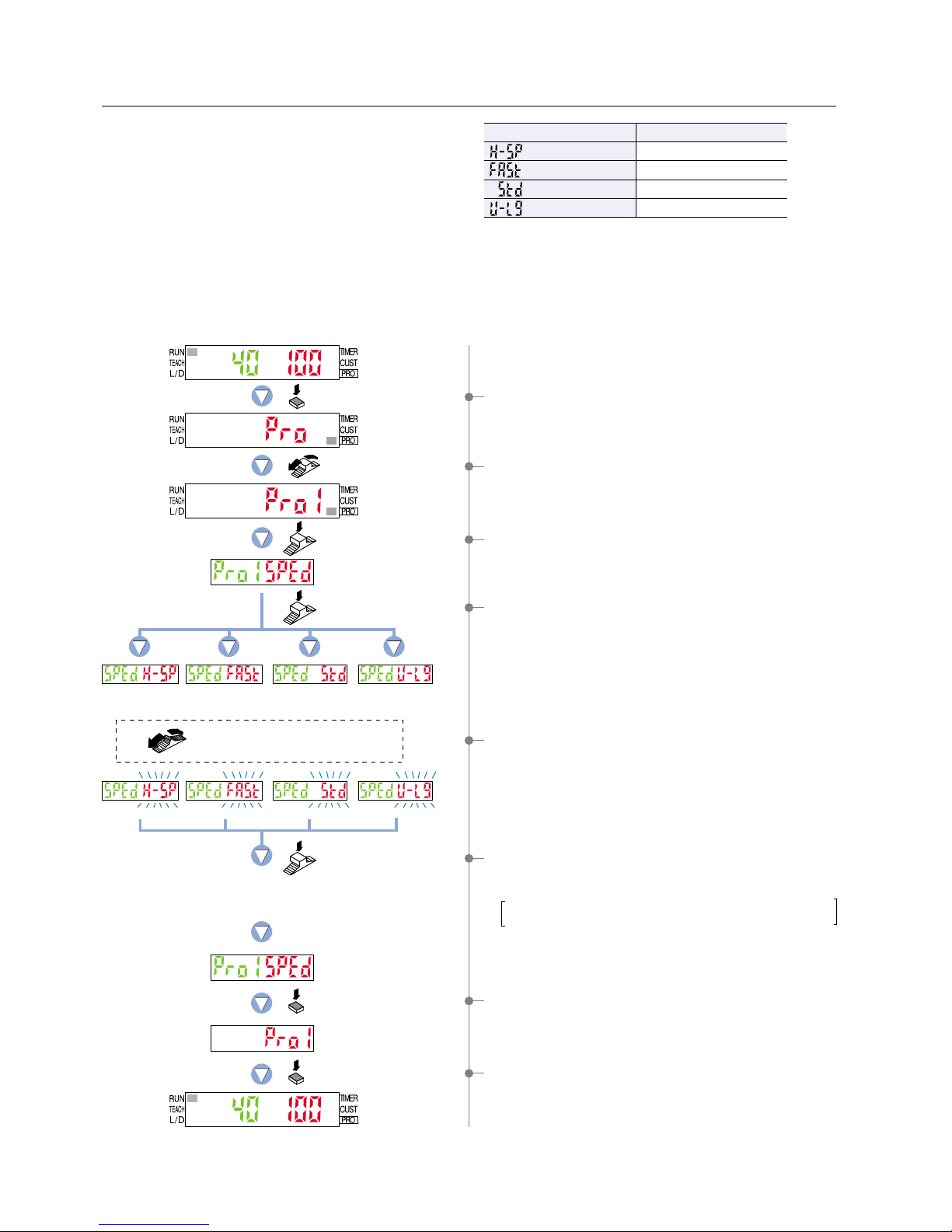
5-2. Response Time Change Function
Response time can be switched among four levels:
H-SP (ultra high-speed) / FAST (high-speed) / STD
(standard) / U-LG (ultra long-range).
* The incident light intensity display can display a
maximum value of 4,000 in H-SP (ultra high-speed)
mode and FAST (high-speed) mode. In STD
(standard) mode and U-LG (ultra long-range) mode, it can display up to a maximum value of 9,999.
* In H-SP mode, the interference prevention / copy / single step load / single step save functions cannot be used.
After making settings in H-SP mode and using the copy function or another function in a different mode, turn the
power off and then back on again.
Setting
(high-speed)
(ultra high-speed)
(standard)
(ultra long-range)
150!s (0.15 ms) or less
80!s (0.08 ms) or less
500!s (0.5 ms) or less
4 ms or less
Response time
H-SP
(ultra high-speed)
FAST
(high-speed)
STD
(standard)
U-LG
(ultra long-range)
Press the
MODE key 5 times.
Press the
Jog switch.
Press the
Jog switch.
Press the
Jog switch.
Turn the Jog switch once
toward the ‘
’ direction.
Select the desired response time
by turning the Jog switch.
The digital display will quickly
blink to confirm the setting.
Press the
MODE key once.
Press the
MODE key once.
2Turn the [Jog switch] once toward the ‘’ direction, to select
‘PRO1 mode’.
3Press the [Jog switch] to enter the ‘response time change’
state.
4If the [Jog switch] is pressed, the current response time (red)
will be displayed.
* The factory setting is ‘STD (standard)’.
5If the [Jog switch] is turned, response time (red) will blink on
the digital display.
Select the desired response time.
7If the [MODE key] is pressed once, the amplifier will return to
‘PRO1 mode’.
8Press the [MODE key] once, the amplifier will return to ‘RUN
mode’ (normal sensing operation).
1Press the [MODE key] 5 times to select ‘PRO mode’.
6If the [Jog switch] is pressed, response time (red) will quickly
blink on the digital display and the selected ‘response time’
will be confirmed.
The digital display will not blink (red) if the setting has not
been changed.
* The receiving light sensitivity will be set to the maximum
setting for the mode being set.
25

The digital display will quickly
blink to confirm the setting.
5-3. Hysteresis Function
The hysteresis can be switched to one of three settings (small / standard / large) in all sensing modes except for
hysteresis mode.
H-01 (small) H-02 (standard) H-03 (large)
Turn the Jog switch once
toward the ‘’ direction.
Turn the Jog switch once
toward the ‘
’ direction.
Press the
Jog switch.
Press the
Jog switch.
Press the
Jog switch.
Select the desired hysteresis
by turning the Jog switch.
Press the
MODE key once.
Press the
MODE key once.
Press the
MODE key 5 times.
5If the [Jog switch] is pressed, the current ‘hysteresis’ level
(red) will be displayed.
* The factory setting is ‘H-02 (standard)’.
6If the [Jog switch] is turned, hysteresis level (red) will blink on
the digital display.
Select the desired ‘hysteresis’ level.
7
If the [Jog switch] is pressed, hysteresis level (red) will quickly
blink on the digital display, confirming the ‘hysteresis’ level.
The digital display will not blink (red) if the setting has not
been changed.
4Turn the [Jog switch] once toward the ‘’ direction, to enter
the ‘hysteresis setting’ state.
8If the [MODE key] is pressed once, the amplifier will return to
‘PRO1 mode’.
9Press the [MODE key] once, the amplifier will return to ‘RUN
mode’ (normal sensing operation).
3Press the [Jog switch] to enter the ‘response time change’
state.
2Turn the [Jog switch] once toward the ‘’ direction, to select
‘PRO1 mode’.
1Press the [MODE key] 5 times to select ‘PRO mode’.
26

Select the desired shift amount
by turning the Jog switch.
The percentage adjustment is variable
from approx. 5 % to 200 %,
in increments of 1 %.
5-4. Shift Function
1 %1 %
Press the
MODE key 5 times.
Turn the Jog switch once
toward the ‘
’ direction.
Turn the Jog switch twice
toward the ‘
’ direction.
Press the
Jog switch.
Press the
Jog switch.
Press the
Jog switch.
The digital display will quickly
blink to confirm the setting.
Press the
MODE key once.
Press the
MODE key once.
Shifts the ‘threshold value’ by a certain percentage increment during ‘limit teaching’.
(The percentage adjustment is variable from approx. 5 % to 200 %, in increments of 1 %.)
4Turn the [Jog switch] twice toward the ‘’ direction, to enter
the ‘shift setting’ state.
8If the [MODE key] is pressed once, the amplifier will return to
PRO1 mode’.
9Press the [MODE key] once, the amplifier will return to ‘RUN
mode’ (normal sensing operation).
5If the [Jog switch] is pressed, the current ‘shift amount’ (red)
will be displayed.
* The factory setting is ‘15 %’.
7If the [Jog switch] is pressed, shift amount (red) will quickly
blink on the digital display, confirming the ‘shift amount’
setting.
The digital display will not blink (red) if the setting has not
been changed.
6If the [Jog switch] is turned, shift amount (red) will blink on
the digital display.
Select the desired ‘shift amount’.
If the [Jog switch] is turned once toward the ‘
’ direction,
the shift amount will be
1 %.
If the [Jog switch] is turned once toward the ‘
’ direction,
the shift amount will be
1 %.
The available range for the shift amount:
The percentage adjustment is variable from approx. 5 % to
200 %, in increments of 1 %.
3Press the [Jog switch] to enter the ‘response time change’
state.
2Turn the [Jog switch] once toward the ‘’ direction, to select
‘PRO1 mode’.
1Press the [MODE key] 5 times to select ‘PRO mode’.
27

5-5. M.G.S. Function
The receiving light sensitivity can be set to one of four levels (Level 4 (Note) / Level 3 / Level 2 / Level 1).
Note: Level 4 can only be set in ultra long-range (U-LG) mode.
Level 4 (Note) Level 3 Level 2 Level 1
Press the
MODE key 5 times.
Turn the Jog switch once
toward the ‘
’ direction.
Turn the Jog switch
3 times toward
the ‘
’ direction.
Press the
Jog switch.
Press the
Jog switch.
Press the
Jog switch.
Select the desired sensitivity
by turning the Jog switch.
The digital display will quickly
blink to confirm the setting.
Press the
MODE key once.
Press the
MODE key once.
4Turn the [Jog switch] 3 times toward the ‘’ direction, to
enter the ‘M.G.S. (receiving light sensitivity) setting’ state.
5If the [Jog switch] is pressed, the current ‘receiving light
sensitivity’ (red) will be displayed.
* The factory setting is ‘level 3’.
* If the response time is changed, the maximum sensitivity
for the mode being set is set.
6If the [Jog switch] is turned, receiving light sensitivity (red)
will blink on the digital display.
Select the desired ‘receiving light sensitivity’ level.
* You can check the current incident light intensity at the
instant the jog switch is turned.
Products manufactured after July 2004 (Lot No.: 4G□~)
only.
7If the [Jog switch] is pressed, receiving light sensitivity (red)
will quickly blink on the digital display, confirming the
‘receiving light sensitivity’ level.
The digital display will not blink (red) if the setting has not
been changed.
3Press the [Jog switch] to enter the ‘response time change’
state.
2Turn the [Jog switch] once toward the ‘’ direction, to select
‘PRO1 mode’.
9Press the [MODE key] once, the amplifier will return to ‘RUN
mode’ (normal sensing operation).
8 If the [MODE key] is pressed once, the amplifier will return to
‘PRO1 mode’.
1Press the [MODE key] 5 times to select ‘PRO mode’.
28

5-6. Emission Halt Function
This selects whether the laser is emitted or not.
*
This only stops laser emission, and other operations (such as output operation and timer operation) continue functioning.
Press the
MODE key 5 times.
Press the
Jog switch.
Press the
Jog switch.
Press the
Jog switch.
Laser emission
OFF
Laser emission
ON
Turn the Jog switch once
toward the ‘
’ direction.
Turn the Jog switch
4 times toward
the ‘
’ direction.
Press the
MODE key once.
Press the
MODE key once.
The digital display will quickly
blink to confirm the setting.
Select the desired laser emission state
by turning the Jog switch.
3Press the [Jog switch] to enter the ‘response time change’
state.
8If the [MODE key] is pressed once, the amplifier will return to
‘PRO1 mode’.
9Press the [MODE key] once, the amplifier will return to ‘RUN
mode’ (normal sensing operation).
4Turn the [Jog switch] 4 times toward the ‘’ direction, to
select ‘emission halt setting’.
5If the [Jog switch] is pressed, the current ‘laser emission
state’ (red) will be displayed.
* When the power is turned on, laser emission is set to ON.
(The setting is not stored.)
6If the [Jog switch] is turned, laser emission state (red) will
blink on the digital display.
Select the desired ‘laser emission state’.
7If the [Jog switch] is pressed, laser emission state (red) will
quickly blink on the digital display, and the selected ‘laser
emission state’ will be confirmed.
The digital display will not blink (red) if the setting has not
been changed.
2Turn the [Jog switch] once toward the ‘’ direction, to select
‘PRO1 mode’.
1Press the [MODE key] 5 times to select ‘PRO mode’.
29

PRO2 Mode
6-1. PRO2 Mode Functions and Settings
6
:
Display Switching Function
Refer to p. 32 for setting procedure
PRO2 mode is used mainly for selecting the detailed configuration of the digital display and incident light intensity
data processing.
* Output 1 and output 2 will both be changed to the same settings.
The settings can be carried out in either output 1 mode or output 2 mode.
In RUN mode, the digital display is fixed to either incident light intensity, % or peak
hold / bottom hold display, but you can select it to be a variable display. (Rising /
trailing differential mode allows only incident light intensity display.)
* The factory setting is for ‘no digital display switching’.
* Window comparator mode and hysteresis mode are the only modes that do not
have digital display switching, so that display switching cannot be used in these
modes. (1_SL and 2_SL can be switched.)
Note: The incident light intensity display can display a maximum value
of 4,000 in H-SP (ultra high-speed) mode and FAST (highspeed) mode. In STD (standard) mode and U-LG (ultra longrange) mode, it can display up to a maximum value of 9,999.
● Peak hold / Bottom hold display
This function displays the peak and bottom
numerical value of the incident light intensity.
● Percentage display
This function displays the incident light
intensity within a range of 0P (0 %) to
999P (999 %), based on the threshold
value as a standard.
When fixed at the incident light intensity display, the incident light intensity (changed intensity
in rising / trailing differential mode) is displayed within the range of 0 to 9,999. (Note)
No digital display switching
Press the
Jog switch.
Press the
Jog switch.
Press the
Jog switch.
Press the
Jog switch.
Press the
Jog switch.
Press the
Jog switch.
Blinking by turns.
Incident light intensity
Changed intensity Changed intensity
Threshold value
Blinking by turns.
Threshold value
Incident light intensity
Incident light intensity
Peak hold value for changed intensity
Digital display switching
● Incident light intensity display
Normal mode
● Incident light intensity display
Rising / Trailing differential mode
30

:
Display Turning Function
This function can be used to invert the display orientation, according to the
direction of amplifier installation.
* The factory setting is ‘Turn OFF’.
This function turns off the digital display to reduce current consumption.
If no operations are performed for 20 sec., the letters ‘ ’ will blink and then the
digital display will turn off.
If the [MODE key] or the [Jog switch] are operated, the digital display will light up
again.
* The factory setting is ‘ECO OFF’.
This selects whether the peak hold value / bottom hold value during the hold ON
period or the peak hold value / bottom hold value within the digital display refresh
period is displayed.
* The hold function starts operating from the value at the point when operation
returns to RUN mode.
:
Period Holding Function
: ECO Mode Function
Time
Peak
hold
Bottom
hold
Incident light intensity
When set to Turn OFF When set to Turn ON
Display indicates the peak
value or bottom value within
the graph area ‘ ’.
Display indicates the peak
value or bottom value within
the graph area ‘ ’.
When the period holding function in PRO2 mode is set to hold ON, the peak hold value / bottom hold
value is displayed during the hold ON period.
Please note that the peak hold and bottom hold values will be resampled
consecutively.
2068
146
705
1820
Display Timing for Peak Hold and Bottom Hold
When set to ECO OFF
The current incident light intensity value can be stored.
:
Current Value Storage Function
When ECO mode is OFF:
40 mA or less (at 24 V supply voltage)
When ECO mode is ON:
33 mA or less (at 24 V supply voltage)
This displays the stored incident light intensity value and the present incident light
intensity value at the same time so that you can check for things such as drops in
incident light intensity.
:
Stored Value Comparison Function
When set to ECO ON
Refer to p. 33 for setting procedure
Refer to p. 34 for setting procedure
Refer to p. 35 for setting procedure
Refer to p. 36 for setting procedure
Refer to p. 37 for setting procedure
Current Consumption
31

6-2. Display Switching Function
In RUN mode, the digital display is fixed to either incident light intensity, % or peak hold / bottom hold display, but
you can select it to be a variable display.
* The factory setting is for ‘no digital display switching’.
Press the
MODE key 5 times.
Display
switching
No display
switching
Turn the Jog switch twice
toward the ‘
’ direction.
Press the
Jog switch.
Press the
Jog switch.
Press the
Jog switch.
Select the desired display setting
by turning the Jog switch.
Press the
MODE key once.
Press the
MODE key once.
The digital display will quickly
blink to confirm the setting.
4If the [Jog switch] is pressed, the current ‘display switching
4If the [Jog switch] is pressed, the current ‘display switching
setting’ (red) will be displayed.
* The factory setting is ‘No display switching’.
5If the [Jog switch] is turned, display switching setting (red)
will blink on the digital display.
Select the desired ‘display switching setting’.
6If the [Jog switch] is pressed, display switching setting (red)
will quickly blink on the digital display, and the selected
‘display switching setting’ will be confirmed.
The digital display will not blink (red) if the setting has not
been changed.
3Press the [Jog switch] to enter the ‘display switching’ state.
2Turn the [Jog switch] twice toward the ‘’ direction, to
select ‘PRO2 mode’.
7If the [MODE key] is pressed once, the amplifier will return to
‘PRO2 mode’.
8Press the [MODE key] once, the amplifier will return to ‘RUN
mode’ (normal sensing operation).
1Press the [MODE key] 5 times to select ‘PRO mode’.
32

6-3. Display Turning Function
Turn OFF
This function can be used to invert the display orientation, according to the direction of amplifier installation.
Turn ON
When turn ON
Press the
MODE key 5 times.
Turn the Jog switch twice
toward the ‘
Ⳮ’ direction.
Turn the Jog switch once
toward the ‘
Ⳮ’ direction.
Press the
Jog switch.
Press the
Jog switch.
Press the
Jog switch.
Select the desired display orientation
by turning the Jog switch.
The digital display will quickly
blink to confirm the setting.
Press the
MODE key once.
Press the
MODE key once.
5If the [Jog switch] is pressed, the current ‘display orientation’
(red) will be displayed.
* The factory setting is Turn OFF.
6If the [Jog switch] is turned, display orientation (red) will blink
on the digital display.
Select the desired ‘display orientation’.
7If the [Jog switch] is pressed, display orientation (red) will
quickly blink on the digital display, and the selected ‘display
orientation’ will be confirmed.
The digital display will not blink (red) if the setting has not
been changed.
4Turn the [Jog switch] once toward the ‘Ⳮ’ direction, to enter
the ‘display turning setting’ state.
9Press the [MODE key] once, the amplifier will return to ‘RUN
mode’ (normal sensing operation).
To return the display to the original state, select the setting
‘Turn OFF’.
8If the [MODE key] is pressed once, the amplifier will return to
‘PRO2 mode’.
3Press the [Jog switch] to enter the ‘display switching’ state.
2Turn the [Jog switch] twice toward the ‘Ⳮ’ direction, to
select ‘PRO2 mode’.
1Press the [MODE key] 5 times to select ‘PRO mode’.
33

6-4. ECO Mode Function
This function turns off the digital display to reduce power consumption.
If no operations are performed for 20 sec., the letters ‘ ’ (green) will blink and then the digital display will turn off.
If the [MODE key] or the [Jog switch] are operated, the digital display will light up again.
Only when
ECO ON
ECO
OFF
ECO
ON
When set to ECO OFF When set to ECO ON
When ECO mode is OFF:
40 mA or less (at 24 V supply voltage)
When ECO mode is ON:
33 mA or less (at 24 V supply voltage)
Current Consumption
Press the
MODE key 5 times.
Turn the Jog switch twice
toward the ‘
Ⳮ’ direction.
Turn the Jog switch twice
toward the ‘
Ⳮ’ direction.
Press the
Jog switch.
Press the
Jog switch.
Press the
Jog switch.
Press the
MODE key once.
Press the
MODE key once.
The digital display will quickly
blink to confirm the setting.
No operation has been
performed for 20 sec.
Operating either the
MODE key or the Jog
switch causes the
display to light up
again.
Select between ECO ON / ECO OFF
by turning the Jog switch.
1Press the [MODE key] 5 times to select ‘PRO mode’.
3Press the [Jog switch] to enter the ‘display switching’ state.
2Turn the [Jog switch] twice toward the ‘Ⳮ’ direction, to
select ‘PRO2 mode’.
8If the [MODE key] is pressed once, the amplifier will return to
‘PRO2 mode’.
9Press the [MODE key] once, the amplifier will return to ‘RUN
mode’ (normal sensing operation).
4Turn the [Jog switch] twice toward the ‘Ⳮ’ direction, to enter
the ‘ECO mode setting’ state.
5If the [Jog switch] is pressed, the current ‘ECO mode setting’
(red) will be displayed.
* The factory setting is ‘ECO OFF’.
6If the [Jog switch] is turned, ‘ECO mode setting’ (red) will
blink on the digital display.
Select from either ‘ECO ON’ or ‘ECO OFF’.
0Only when the amplifier is set to ECO ON and no operations
are performed for 20 sec., will the letters ‘ ’ (green) blink
and the digital display then turn off.
AIf the [MODE key] or the [Jog switch] are operated, the
digital display will light up again.
To return the amplifier to the original state, select the setting
ECO OFF.
7If the [Jog switch] is pressed, ‘ECO mode setting’ (red) will
quickly blink on the digital display, and the selected setting
will be confirmed.
The digital display will not blink (red) if the setting has not
been changed.
34

Select the desired display setting
by turning the Jog switch.
6-5. Period Holding Function
This selects whether the peak hold value / bottom hold value during the hold ON period or the peak hold value /
bottom hold value within the digital display refresh period is displayed. When hold ON is set, holding starts from
the point when the peak / bottom display appears in RUN mode.
* Before using this function, set the display switching function to ‘Display switching’. (Refer to p. 32.)
Press the
MODE key 5 times.
Press the
Jog switch.
Press the
Jog switch.
Press the
Jog switch.
The digital display will quickly
blink to confirm the setting.
Press the
MODE key once.
Press the
MODE key once.
Turn the Jog switch twice
toward the ‘
Ⳮ’ direction.
Turn the Jog switch 3 times
toward the ‘
Ⳮ’ direction.
Period
holding OFF
Period
holding ON
5If the [Jog switch] is pressed, the current ‘period holding
setting’ (red) will be displayed.
* The factory setting is ‘period holding OFF’.
6If the [Jog switch] is turned, ‘period holding setting’ (red) will
blink on the digital display.
Select from either ‘period holding OFF’ or ‘period holding
ON’.
7If the [Jog switch] is pressed, period holding setting (red) will
quickly blink on the digital display, and the selected setting
will be confirmed.
The digital display will not blink (red) if the setting has not
been changed.
4Turn the [Jog switch] 3 times toward the ‘Ⳮ’ direction, to
enter the ‘period holding setting’ state.
3Press the [Jog switch] to enter the ‘display switching’ state.
2Turn the [Jog switch] twice toward the ‘Ⳮ’ direction, to
select ‘PRO2 mode’.
8If the [MODE key] is pressed once, the amplifier will return to
‘PRO2 mode’.
9Press the [MODE key] once, the amplifier will return to ‘RUN
mode’ (normal sensing operation).
1Press the [MODE key] 5 times to select ‘PRO mode’.
35

6-6. Current Value Storage Function
The current incident light intensity value can be stored.
Press the
MODE key 5 times.
Press the
Jog switch.
Press the
Jog switch.
Press the
Jog switch.
Turn the Jog switch twice
toward the ‘Ⳮ’ direction.
Turn the Jog switch 4 times
toward the ‘Ⳮ’ direction.
Press the
MODE key once.
The digital display will quickly
blink to confirm the setting.
Press the
MODE key once.
5If the [Jog switch] is pressed, the current ‘incident light
intensity’ (red) will be displayed.
7If the [MODE key] is pressed once, the amplifier will return to
‘PRO2 mode’.
8Press the [MODE key] once, the amplifier will return to ‘RUN
mode’ (normal sensing operation).
6If the [Jog switch] is pressed, incident light intensity (red) will
quickly blink on the digital display, and the data will be
stored.
4Turn the [Jog switch] 4 times toward the ‘Ⳮ’ direction, to
enter the ‘current value storage setting’ state.
3Press the [Jog switch] to enter the ‘display switching’ state.
2Turn the [Jog switch] twice toward the ‘Ⳮ’ direction, to
select ‘PRO2 mode’.
1Press the [MODE key] 5 times to select ‘PRO mode’.
36
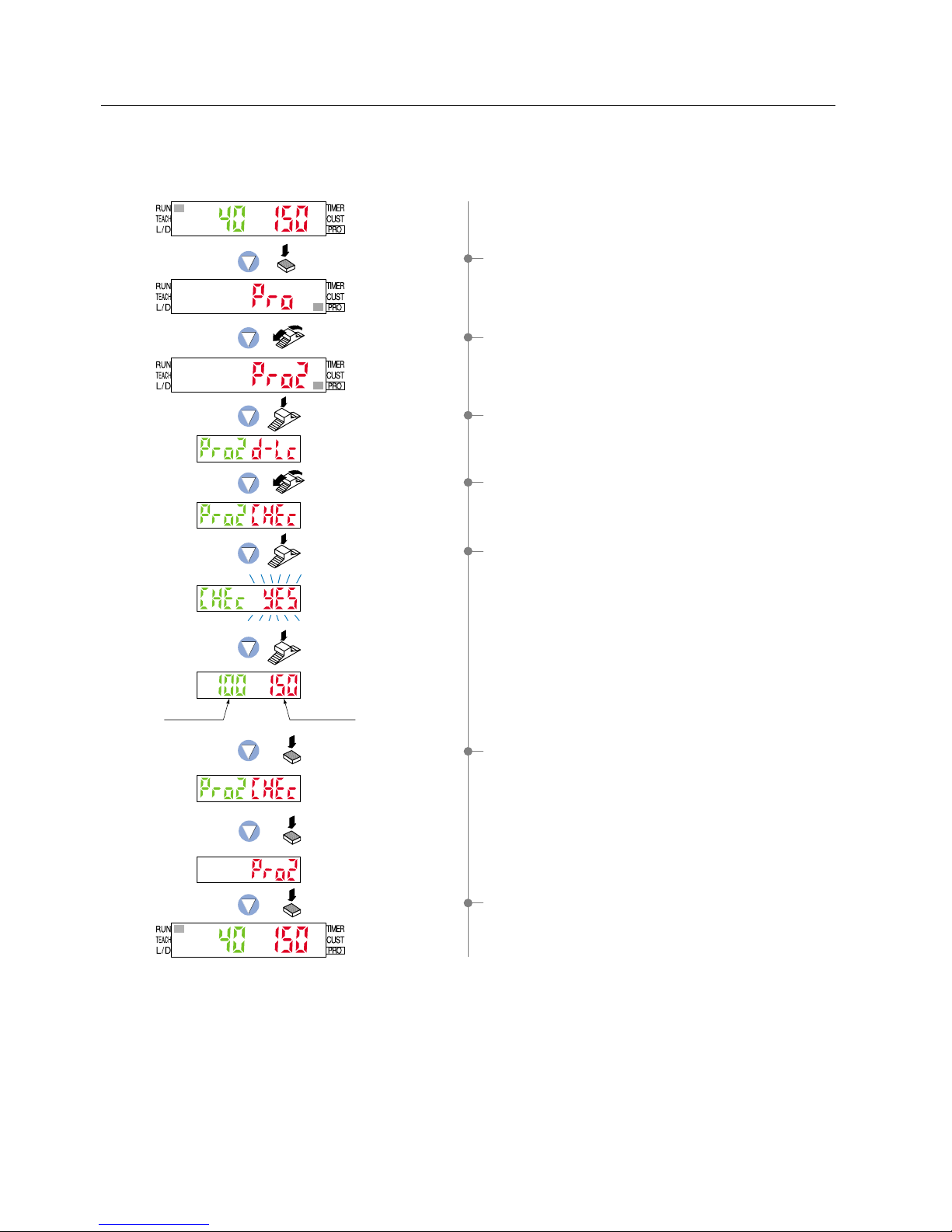
6-7. Stored Value Comparison Function
This displays the stored incident light intensity value and the present incident light intensity value at the same
time so that you can check for things such as drops in incident light intensity.
* Before using the stored value comparison function, you need to store the present incident light intensity.
Present valueStored value
Press the
MODE key 5 times.
Turn the Jog switch twice
toward the ‘
Ⳮ’ direction.
Turn the Jog switch 5 times
toward the ‘Ⳮ’ direction.
Press the
Jog switch.
Press the
Jog switch.
Press the
Jog switch.
Press the
MODE key once.
Press the
MODE key once.
Press the
MODE key once.
1Press the [MODE key] 5 times to select ‘PRO mode’.
3Press the [Jog switch] to enter the ‘display switching’ state.
4Turn the [Jog switch] 5 times toward the ‘Ⳮ’ direction, to
enter the ‘stored value comparison setting’ state.
5If the [Jog switch] is pressed twice, the incident light intensity
(green) that was stored by the present value storage function
and the present incident light intensity (red) will be displayed.
6If the [MODE key] is pressed twice, the amplifier will return to
‘PRO2 mode’.
7Press the [MODE key] once, the amplifier will return to ‘RUN
mode’ (normal sensing operation).
2Turn the [Jog switch] twice toward the ‘Ⳮ’ direction, to
select ‘PRO2 mode’.
37

PRO3 Mode
7-1. PRO3 Mode Functions and Settings
7
:
Data Bank Load Function
:
Data Bank Save Function
This function allows settings from the data bank to be selected and then loaded.
This feature allows settings to be changed quickly at times of reconfiguration, etc.
You can select whether the settings for only one amplifier are loaded or the
settings for all amplifiers on the right side that are connected via optical
communication are loaded all in a single step.
Refer to p. 39 for setting procedure
Refer to p. 40 for setting procedure
This function saves amplifier settings.
Up to 3 sets of settings can be saved in ‘ ’, ‘ ’ and ‘ ’.
You can select whether the settings for only one amplifier are saved or the
settings for all amplifiers on the right side that are connected via optical
communication are saved all in a single step.
Data bank
PRO3 mode can load settings from the data bank and can save settings to the data bank.
The LS-400 series incorporates an internal memory for storing setting.
Three different sets of settings can be stored within the data banks, in channels 1 ( ) to 3 ( ).
These settings will not be deleted, unless they are intentionally overwritten by the data bank save setting
function.
Setting within the data bank will not be deleted, even when a reset is performed using the ‘9-4. Setting Reset
Function’ from ‘PRO5 Mode’ on p. 50.
Optical communication
When the collective data bank load / save function or copy function is used via optical communication, loading /
saving or copy of the setting can be carried out only to the amplifiers (sub units) connected on the right side of
the amplifier (main unit). However, if the amplifier (sub unit) is being connected (the indicator blinks), PRO mode
is being set or the transmission change to permit / not to permit function is set to ‘not to permit’, loading / saving
or copy is not carried out. Furthermore, the sensing operation stops during optical communication.
(
(
To copy the same settings to the 4th and subsequent channels:
Use the 4-channel data bank load / save function and the copy function.
To copy the same settings to the 1st and subsequent channels:
Use the 1-channel single step data bank load / save function and the copy function.
1CH 2CH 3CH 4CH 5CH 6CH 7CH 8CH 9CH 10CH 11CH 12CH 13CH 14CH 15CH 16CH
Example: When 16 amplifiers are connected in the side-by-side configuration
1CH 2CH 3CH 4CH 5CH 6CH 7CH 8CH 9CH 10CH 11CH 12CH 13CH 14CH 15CH 16CH
Communication direction
* The incident light intensity display changes while
optical communication is in progress.
38

7-2. Data Bank Load Function
This function allows settings from the data bank to be selected and then loaded.
This feature allows settings to be changed quickly at times of reconfiguration, etc.
You can select whether the settings for only one amplifier are loaded or the settings for all amplifiers on the right
side that are connected via optical communication are loaded all in a single step.
Channel 1 Channel 3Channel 2
Press the
MODE key 5 times.
Turn the Jog switch 3 times
toward the ‘
Ⳮ’ direction.
Press the
Jog switch.
Press the
Jog switch.
Press the
Jog switch.
Press the
Jog switch.
Loading one
amplifier only
Loading all amplifiers
in a single step
Turn the Jog switch to select the
desired channel for loading.
Turn the Jog switch to select whether to load
settings for one amplifier or all amplifiers
in a single step.
Press the
MODE key
once.
Press the
MODE key
once.
The digital display will blink
to confirm the setting.
The digital
display will
blink to
confirm
the setting.
The digital display
will scroll twice.
* When loading only the
following one amplifier
* When loading all amplifiers
in a single step
1Press the [MODE key] 5 times to select ‘PRO mode’.
8
If the [Jog switch] is pressed, the letters ‘ ’ (red) will blink.
2Turn the [Jog switch] 3 times toward the ‘Ⳮ’ direction, to
select ‘PRO3 mode’.
3Press the [Jog switch] to enter the ‘data bank load setting’
state.
4If the [Jog switch] is pressed, the current setting will be
displayed.
5Turn the [Jog switch] to select whether to load settings for
one amplifier or all amplifiers in a single step.
6If the [Jog switch] is pressed, the selected setting will be
confirmed.
7If the [Jog switch] is turned, the ‘channel’ will be changed.
Select the desired ‘channel’ for loading.
0If the [MODE key] is pressed once, the amplifier will return to
‘PRO3 mode’.
APress the [MODE key] once, the amplifier will return to ‘RUN
mode’ (normal sensing operation).
9If the [Jog switch] is pressed while ‘ ’ (red) is blinking, the
settings will be loaded from the selected ‘channel’. ‘ ’
(red) will quickly blink, and ‘ ’ (red) will blink to confirm
the new setting.
If loading settings for all amplifiers in a single step, the
display will scroll twice and then the channels being loaded
will blink (red) and the settings will be confirmed.
39

7-3. Data Bank Save Function
This function saves amplifier settings.
Up to 3 sets of settings can be saved using ‘ ’ ‘ ’ and ‘ ’ .
You can select whether the settings for only one amplifier are saved or the settings for all amplifiers on the right
side that are connected via optical communication are saved all in a single step.
The digital display
will scroll twice.
The digital display will blink
to confirm the setting.
Press the
MODE key 5 times.
Turn the Jog switch 3 times
toward the ‘
Ⳮ’ direction.
Turn the Jog switch once
toward the ‘
Ⳮ’ direction.
Press the
Jog switch.
Press the
Jog switch.
Press the
Jog switch.
Press the
Jog switch.
Press the
MODE key
once.
Press the
MODE key
once.
Turn the Jog switch to select the
desired channel for saving.
* When saving only the
following one amplifier
* When saving all amplifiers
in a single step
Saving all amplifiers
in a single step
Saving one
amplifier only
Turn the Jog switch to select whether to save
settings for one amplifier or all amplifiers
in a single step.
The digital
display will
blink to
confirm
the setting.
Channel 1 Channel 3Channel 2
1Press the [MODE key] 5 times to select ‘PRO mode’.
9
If the [Jog switch] is pressed, the letters ‘ ’ (red) will blink.
2Turn the [Jog switch] 3 times toward the ‘Ⳮ’ direction, to
select ‘PRO3 mode’.
3Press the [Jog switch] to enter the ‘data bank load setting’
state.
4Turn the [Jog switch] once toward the ‘Ⳮ’ direction, to enter
the ‘data bank save setting’ state.
5If the [Jog switch] is pressed, the current setting will be
displayed.
6Turn the [Jog switch] to select whether to save settings for
one amplifier or all amplifiers in a single step.
7If the [Jog switch] is pressed, the selected setting will be
confirmed.
8If the [Jog switch] is turned, the ‘channel’ will be changed.
Select the desired ‘channel’ for saving.
AIf the [MODE key] is pressed once, the amplifier will return to
‘PRO3 mode’.
0
If the [Jog switch] is pressed while ‘ ’ (red) is blinking, the
settings will be saved to the selected ‘channel’.
‘ ’ (red) will quickly blink, and ‘ ’ (red) will blink to
confirm the new setting.
If saving settings for all amplifiers in a single step, the display
will scroll twice and then the channels being saved will blink
(red) and the settings will be confirmed.
BPress the [MODE key] once, the amplifier will return to ‘RUN
mode’ (normal sensing operation).
40

PRO4 Mode
8-1. PRO4 Mode Functions and Settings
8
PRO4 mode is mainly used for configuring communication with sub units and external input modes.
By utilizing the optical communications function, the settings information from the
operating amplifier can be copied to other connected amplifiers. (Except for data bank
contents) However, the 0-Adjust setting function and transmission change to permit /
not to permit function will not be copied. As well, in amplifiers in which the optical
communications settings change function has been locked, copying will not occur.
When attempting to perform single step load / save / copy operations using the
data bank load function and data bank save function from PRO3 mode, and copy
function from PRO4 mode, if the transmission change has not been permitted,
then only the specified amplifier will be locked. Therefore single step load / save /
copy operations will be disabled.
* The factory setting is ‘Lock OFF’.
Selects ‘emission halt’, ‘full-auto teaching’ or ‘limit teaching’ using external input
wires.
Note: Output operations are undefined only for the response time.
When the output signal is being received by a PLC or other device, set the timer to 2 ms
sensor
response time or longer.
Example: For the response time in STD mode (500 !s)
Timer period: 2 ms
0.5 ms (500 !s) 2.5 ms
Signal conditions:High...
5 V to V, or open (NPN type), 4 V to V (PNP type)
Low...0 to
2 V (NPN type), 0 to 0.6 V, or open (PNP type)
Note:
After teaching is finished, output operations are undefined only for the response time.
When the output signal is being received by a PLC or other device, set the timer to the sensor
response time or longer.
The incident light intensity at the instant teaching is recognized is set as the standard threshold value.
Notes: 1) Pass the sensing object past the sensor once while an input signal is being input.
2) After teaching is finished, output operations are undefined only for the response time.
When the output signal is being received by a PLC or other device, set the timer to the sensor
response time or longer.
This function is used for not storing the threshold value obtained from external
input teaching into the EEPROM.
It prevents unnecessary writing to the EEPROM.
* Note that when the power is turned off, the threshold value becomes the value
that was last stored in memory.
External input
High (NPN type: Low)
Low (NPN type: High)
High (NPN type: Low)
Low (NPN type: High)
High (NPN type: Low)
Low (NPN type: High)
During teaching
Normal operation
During teaching
Normal operation
Emission halt
Emission
3 ms or more
3 ms or more
3 ms or more (Note 1)
2 ms 2 ms
(Note)
Emission halt
Limit teaching
2 ms 2 ms
2 ms
External input
Full-auto teaching
(Note)
External input
In case of selecting emission halt ( )
Refer to p. 42 for setting procedure
Refer to p. 43 for setting procedure
Refer to p. 44 for setting procedure
Equipped with cable type only.
Refer to p. 45 for setting procedure
Equipped with cable type only.
: Copy Function
: Backup Function
:
External Input Switch
Setting Function
:
Selection for transmission
change to permit / not to permit
Time chart
In case of selecting limit teaching ( , )
In case of selecting full-auto teaching ( )
(Note 2)
41

8-2. Copy Function
By utilizing the optical communications function, the settings information from the operating amplifier can be
copied to other connected amplifiers. (Except for data bank contents) However, the 0-Adjust function and
transmission change to permit / not to permit function will not be copied. However, in amplifiers in which the
transmission change has not been permitted, copying will not occur.
Please refer to p. 38 Optical communications for the direction of optical communication.
Press the
MODE key 5 times.
Turn the Jog switch 4 times
toward the ‘
’ direction.
Press the
Jog switch.
Press the
Jog switch.
Press the
Jog switch.
Press the
MODE key once.
Press the
MODE key once.
The digital display will blink
3 times to confirm the setting.
The digital display
will scroll (twice).
Also displayed
on amplifiers
on which copy
is done.
1Press the [MODE key] 5 times to select ‘PRO mode’.
3Press the [Jog switch] to enter the ‘copy setting’ state.
6If the [MODE key] is pressed once, the amplifier will return to
‘PRO4 mode’.
7Press the [MODE key] once, the amplifier will return to ‘RUN
mode’ (normal sensing operation).
5
If the [Jog switch] is pressed while ‘ ’ (red) is blinking, the
digital display will scroll (twice) and the settings information will
be copied. Then ‘ ’ (red) will blink 3 times, confirming the
setting.
However, for amplifiers in which the transmission change
has not been permitted, ‘ ’ (red) will blink 3 times.
*
When communication error has occurred, ‘ ’ (red) will be
displayed. Confirm that all amplifiers are properly connected to
each other.
4
If the [Jog switch] is pressed, the letters ‘ ’ (red) will blink.
2Turn the [Jog switch] 4 times toward the ‘’ direction, to
select ‘PRO4 mode’.
42

8-3. Selection for Transmission Change to Permit / Not to Permit
When attempting to perform single step load / save / copy operations using the setting condition data bank load
function and data bank save function from PRO3 mode, and copy function from PRO4 mode, if the transmission
change has not been permitted, then only the specified amplifier will be locked. Therefore single step load / save /
copy operations will be disabled.
Lock OFF
(Permit)
Lock ON
(Not permit)
Press the
MODE key 5 times.
Turn the Jog switch 4 times
toward the ‘’ direction.
Press the
Jog switch.
Press the
Jog switch.
Press the
Jog switch.
Turn the Jog switch once
toward the ‘
’ direction.
Press the
MODE key once.
Press the
MODE key once.
The digital display will quickly
blink to confirm the setting.
Select from Lock ON / Lock OFF
by turning the Jog switch.
1Press the [MODE key] 5 times to select ‘PRO mode’.
3Press the [Jog switch] to enter the ‘copy setting’ state.
4Turn the [Jog switch] once toward the ‘’ direction, to enter
the ‘selection for transmission change to permit / not to
permit’ state.
5If the [Jog switch] is pressed, the current setting (red) will be
displayed.
* The factory setting is ‘Lock OFF (permit)’.
2Turn the [Jog switch] 4 times toward the ‘’ direction, to
select ‘PRO4 mode’.
6If the [Jog switch] is turned, the setting (red) will blink.
Select from either ‘Lock ON’ or ‘Lock OFF’.
8If the [MODE key] is pressed once, the amplifier will return to
‘PRO4 mode’.
7If the [Jog switch] is pressed, the setting (red) will quickly
blink on the digital display, and ‘Lock ON / OFF’ will be
confirmed.
The digital display will not blink (red) if the setting has not
been changed.
9Press the [MODE key] once, the amplifier will return to ‘RUN
mode’ (normal sensing operation).
43

8-4. External Input Switch Setting Function
Selects ‘emission halt’, ‘full-auto teaching’ or ‘limit teaching’ using external input wires.
* Equipped with cable type only.
The digital display will quickly
blink to confirm the setting.
Press the
MODE key 5 times.
Turn the Jog switch 4 times
toward the ‘
’ direction.
Turn the Jog switch twice
toward the ‘
’ direction.
Press the
Jog switch.
Press the
Jog switch.
Emission
halt
Full-auto
teaching
Limit
teaching
Plus side
Limit
teaching
Minus side
Press the
Jog switch.
Select mode
by turning the Jog switch.
Press the
MODE key once.
Press the
MODE key once.
1Press the [MODE key] 5 times to select ‘PRO mode’.
3Press the [Jog switch] to enter the ‘copy setting’ state.
2Turn the [Jog switch] 4 times toward the ‘’ direction, to
select ‘PRO4 mode’.
4Turn the [Jog switch] twice toward the ‘’ direction, to enter
the ‘external input switch setting’ state.
8If the [MODE key] is pressed once, the amplifier will return to
‘PRO4 mode’.
9Press the [MODE key] once, the amplifier will return to ‘RUN
mode’ (normal sensing operation).
5If the [Jog switch] is pressed, the current setting (red) will be
displayed.
* The factory setting is ‘emission halt’.
6If the [Jog switch] is turned, external input mode (red) will
blink on the digital display.
Select mode.
7If the [Jog switch] is pressed, external input mode (red) will
quickly blink on the digital display, confirming the mode.
The digital display will not blink (red) if the setting has not
been changed.
44
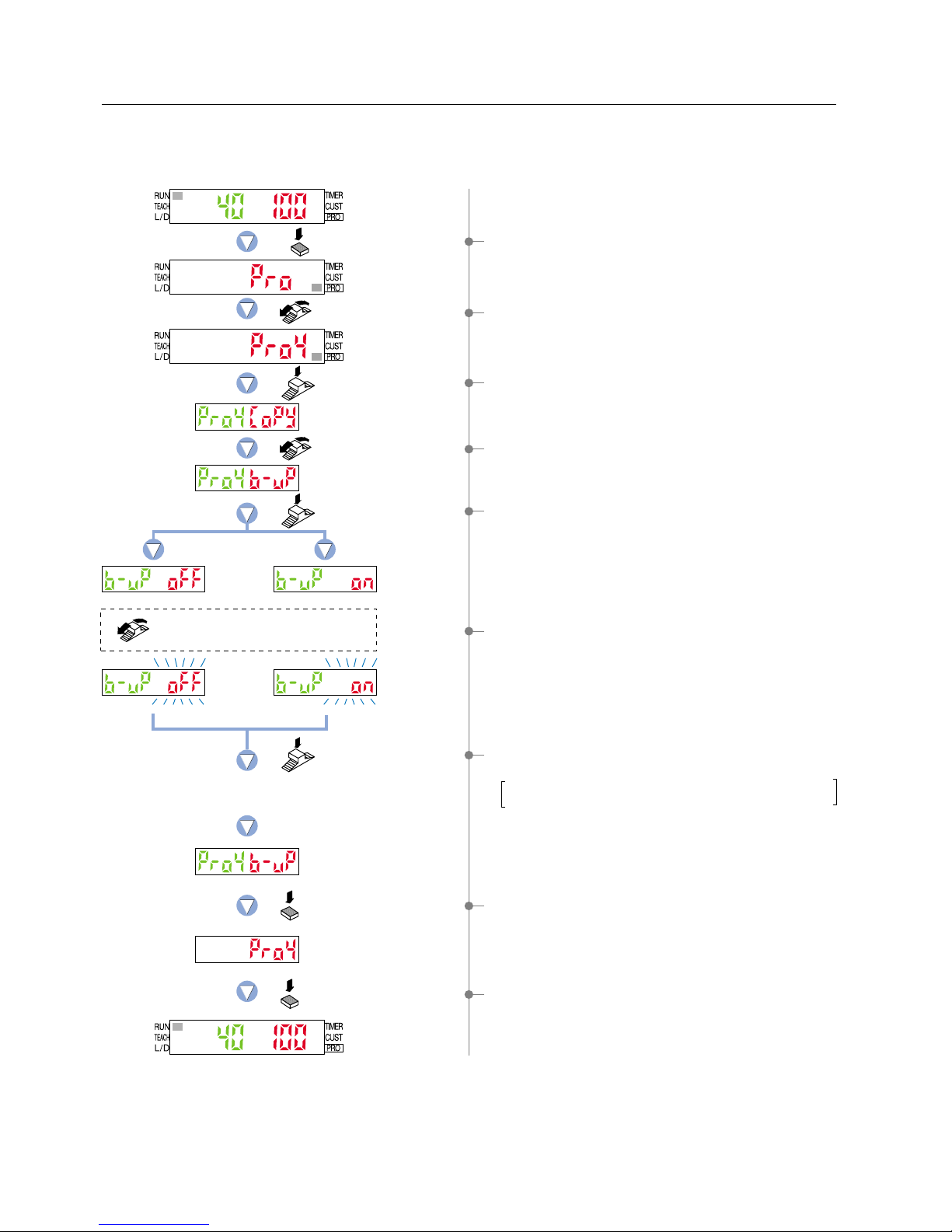
8-5. Backup Function
This function is used for not storing the threshold value obtained from external input teaching into the EEPROM.
It prevents unnecessary writing to the EEPROM.
* Equipped with cable type only.
Backup
OFF
Backup
ON
Press the
MODE key 5 times.
Turn the Jog switch 4 times
toward the ‘
’ direction.
Turn the Jog switch 3 times
toward the ‘
’ direction.
Press the
Jog switch.
Press the
Jog switch.
Press the
Jog switch.
Press the
MODE key once.
Press the
MODE key once.
The digital display will quickly
blink to confirm the setting.
Select from backup ON / backup OFF
by turning the Jog switch.
1Press the [MODE key] 5 times to select ‘PRO mode’.
3Press the [Jog switch] to enter the ‘copy setting’ state.
2Turn the [Jog switch] 4 times toward the ‘’ direction, to
select ‘PRO4 mode’.
4Turn the [Jog switch] 3 times toward the ‘’ direction, to
enter the ‘backup setting’ state.
8If the [MODE key] is pressed once, the amplifier will return to
‘PRO4 mode’.
9Press the [MODE key] once, the amplifier will return to ‘RUN
mode’ (normal sensing operation).
5If the [Jog switch] is pressed, the current setting (red) will be
displayed.
* The factory setting is ‘Backup OFF’.
6If the [Jog switch] is turned, the setting (red) will blink on the
digital display.
Select from either ‘Backup ON’ or ‘Backup OFF’.
7If the [Jog switch] is pressed, the setting (red) will quickly
blink on the digital display, confirming ‘Backup ON / OFF’.
The digital display will not blink (red) if the setting has not
been changed.
45

PRO5 Mode
9-1. PRO5 Mode Functions and Settings
9
Code Setting
[Code Setting Table]
PRO5 mode allows code setting, 0-adjust, setting reset (re-initialized), and setting of CUSTOM mode display.
The LS-400 series contain certain encoded basic information that can be set by inputting a 8-digit code.
The functions that may be set using direct coding are: Response time, Hysteresis, Output operation, M.G.S.,
External input mode, Timer operation and CUSTOM mode display.
* Output 1 and output 2 settings are possible for output operation only.
Green digital display
Green digital display
● Green digital display
● Red digital display
Red digital display
Red digital display
: The highlighted line indicates the default code (factory setting).
: The highlighted line indicates the default code (factory setting).
Note: Connector type LS-401(P) shows only ‘ ’.
Note
If function settings (Response time, Hysteresis, Output operation, M.G.S., External input mode, Timer operation,
CUSTOM mode display, etc.) are changed, the changes will be reflected in the configuration and the numerical
value of the code will be automatically updated.
Output operation
(Output 1Output 2)
Timer operation Response time
CUSTOM
Level 3
Level 2
Level 1
Level 4
-
-
-
-
-
-
-
-
-
-
-
-
-
-
-
-
-
-
-
-
-
-
-
-
-
-
-
STD
H-SP
FAST
U-LG
NON
ON-delay
OFF-delay
ONE-SHOT
H-02
H-02
H-03
H-03
H-01
H-01
L-ONL-ON
L-OND-ON
D-ONL-ON
D-OND-ON
M.G.S.
Sensing mode
-
-
-
-
-
-
-
-
-
-
-
-
-
-
-
-
-
-
Direct
code
Transmission
change lock
Backup
Hysteresis
Emission halt
Emission halt
Full-auto
Full-auto
Limit
Limit
Limit
Limit
OFF
ON
OFF
ON
OFF
ON
ON
OFF
ON
OFF
ON
OFF
ON
OFF
Response time
M.G.S.
Emission halt
Data bank load
Code setting
Normal 2 output
Window comparator
Rising differential
Trailing differential
Hysteresis
Output 2 OFF
Direct
code
External
input mode
Direct
code
Direct
code
Direct
code
Direct
code
First digit Second digit Third digit Fourth digit
First digit Second digit Third digit Fourth digit
Direct
code
Direct
code
46

The input of a 8-digit code allows the configuration to be set directly, without the
need to set each individual function.
This function allows for automatic zeroing of the incident light intensity.
This function will cause all configuration settings to revert to factory settings.
However, any settings that have been saved within the data bank will not be
changed.
Please refer to the ‘3-2. Factory Settings’ on p. 4.
This selects one function that you would like to display in the navigation display in
CUSTOM mode.
Refer to p. 50 for setting procedure
Refer to p. 51 for setting procedure
Refer to p. 49 for setting procedure
Refer to p. 48 for setting procedure
:
0-Adjust Setting Function
:
Setting Reset Function
:
CUSTOM Mode Display Function
:
Code Setting Function
47

9-2. Code Setting Function
The input of a 8-digit code allows the configuration to be set directly, without the need to set each individual
function.
Press the
MODE key 5 times.
Turn the Jog switch 5 times
toward the ‘
’ direction.
Press the
Jog switch.
Press the
Jog switch.
Press the
Jog switch.
Select the desired code
by turning the Jog switch.
(Repeat this motion 8 times.)
Confirm the
selection
by pressing
the Jog switch.
Press the
MODE key once.
Press the
MODE key once.
The digital display will quickly
blink to confirm the setting.
1Press the [MODE key] 5 times to select ‘PRO mode’.
3Press the [Jog switch] to enter the ‘code setting’ state.
5If the [Jog switch] is pressed, the first green digit will blink.
6Repeat the following motions: select the code by turning the
[Jog switch], then confirm each selection by pressing the
[Jog switch].
Once 8-digit have been input, the digital display (green and
red) will quickly blink, confirming the ‘code’ setting.
The digital display will not blink (green and red) if the
setting has not been changed.
Refer to the ‘Code Setting Table’ on p. 46 for code setting.
2Turn the [Jog switch] 5 times toward the ‘’ direction, to
select ‘PRO5 mode’.
7If the [MODE key] is pressed once, the amplifier will return to
‘PRO5 mode’.
8Press the [MODE key] once, the amplifier will return to ‘RUN
mode’ (normal sensing operation).
4If the [Jog switch] is pressed, the current setting will be
displayed.
* The factory setting is ‘ ’.
48

9-3. 0-Adjust Setting Function
This function allows for automatic zeroing of the incident light intensity.
* The threshold value is not linked to this function, so that after carrying out zero adjustment, be sure to reset the
threshold value.
Press the
MODE key 5 times.
Turn the Jog switch 5 times
toward the ‘
’ direction.
Turn the Jog switch once
toward the ‘
’ direction.
Press the
Jog switch.
Press the
Jog switch.
Press the
Jog switch.
Press the Jog switch to zero
the incident light intensity.
Turn the
Jog switch.
0-Adjust
ON
0-Adjust
OFF
Press the
MODE key once.
Press the
MODE key once.
The digital display will quickly
blink to confirm the setting.
1Press the [MODE key] 5 times to select ‘PRO mode’.
3Press the [Jog switch] to enter the ‘code setting’ state.
2Turn the [Jog switch] 5 times toward the ‘’ direction, to
select ‘PRO5 mode’.
9If the [MODE key] is pressed once, the amplifier will return to
‘PRO5 mode’.
0Press the [MODE key] once, the amplifier will return to ‘RUN
mode’ (normal sensing operation).
4Turn the [Jog switch] once toward the ‘’ direction, to enter
the ‘0-Adjust setting’ state.
7When zero adjustment has been completed
n The current incident light intensity will be displayed.
When zero adjustment has not been completed or has been
cancelled
n The amplifier will return to the ‘0-Adjust setting’ state.
8If the [Jog switch] is pressed to set the desired incident light
intensity to ‘0’, the digital display (red) will quickly blink,
confirming the zero adjustment.
Note: When zero adjustment is performed with the digital
display showing the 2,000 digits or greater, –1,999
digits or less will not be displayed.
6If the [Jog switch] is turned, 0-Adjust setting (red) will blink
on the digital display.
• When setting zero adjustment
n Select ‘SET’, then press the [Jog switch].
• When not performing zero adjustment or when canceling a
‘0-Adjust setting’ that has already been set
n Select ‘OFF’, then press the [Jog switch].
5If the [Jog switch] is pressed, the current setting (red) will be
displayed.
* The factory setting is ‘ ’.
49

9-4. Setting Reset Function
This function will cause all settings to revert to factory settings. However, any settings that have been saved
within the data bank will not be changed.
If the information stored within the data bank is to be changed, then data bank settings must be overwritten with
new settings by using the ‘7-3. Data Bank Save Function’ from ‘PRO3 Mode’, described on p. 40.
Press the
MODE key 5 times.
Turn the Jog switch 5 times
toward the ‘
’ direction.
Press the
Jog switch.
Turn the Jog switch twice
toward the ‘’ direction.
Press the
Jog switch.
Press the
Jog switch.
1Press the [MODE key] 5 times to select ‘PRO mode’.
2Turn the [Jog switch] 5 times toward the ‘’ direction, to
select ‘PRO5 mode’.
3Press the [Jog switch] to enter the ‘code setting’ state.
4Turn the [Jog switch] twice toward the ‘’ direction, to enter
the ‘reset setting’ state.
5If the [Jog switch] is pressed, the letters ‘ ’ (red) will be
displayed.
5
If the [Jog switch] is pressed, the letters ‘ ’ (red) will quickly
blink to reset all setting to factory setting.
After that, the amplifier will automatically return to ‘RUN
mode’ (normal sensing operation).
50

9-5. CUSTOM Mode Display Function
Press the
MODE key 5 times.
Turn the Jog switch 5 times
toward the ‘Ⳮ’ direction.
Turn the Jog switch 3 times
toward the ‘
Ⳮ’ direction.
Press the
Jog switch.
Press the
Jog switch.
Code settingData bank
load
Emission haltM.G.S.Response time
change
Press the
Jog switch.
Press the
MODE key once.
Press the
MODE key once.
Select function
by turning the Jog switch.
This selects one function that you would like to display in the navigation display in CUSTOM mode.
1Press the [MODE key] 5 times to select ‘PRO mode’.
3Press the [Jog switch] to enter the ‘code setting’ state.
7If the [Jog switch] is pressed, the setting will be confirmed.
2Turn the [Jog switch] 5 times toward the ‘Ⳮ’ direction, to
select ‘PRO5 mode’.
4Turn the [Jog switch] 3 times toward the ‘Ⳮ’ direction, to
enter the ‘CUSTOM mode display selection’ state.
8If the [MODE key] is pressed once, the amplifier will return to
‘PRO5 mode’.
9Press the [MODE key] once, the amplifier will return to ‘RUN
mode’ (normal sensing operation).
5If the [Jog switch] is pressed, the current CUSTOM mode
setting (red) will be displayed.
* The factory setting is ‘Response time change’.
6If the [Jog switch] is turned, the CUSTOM mode (red) will
blink on the digital display.
Select the desired function to display in CUSTOM mode.
51

PRO6 Mode
10
10-1. PRO6 Mode Functions and Settings
PRO6 mode is used to set sensing mode (normal / window comparator / rising differential / trailing differential /
hysteresis) and also to set the shift amounts in window comparator mode and hysteresis mode.
Refer to p. 53 for setting procedure
Output 1 can only be set.
Refer to p. 53 for setting procedure
Output 1 can only be set.
Refer to p. 53 for setting procedure
Output 1 can only be set.
Refer to p. 53 for setting procedure
: Normal Mode
: Hysteresis Mode
:
Window Comparator Mode
:
Rising differential /
Trailing differential Mode
This is a sensing mode for setting a single ‘threshold value’ and turning output ON
or OFF.
This is a sensing mode for varying the hysteresis in order to cancel out minute
changes in light intensity.
The teaching method can be selected from 1-level teaching, 2-level teaching or
3-level teaching.
This is a sensing mode for setting two threshold values and tuning output ON or
OFF within the set range.
The teaching method can be selected from 1-level teaching, 2-level teaching or
3-level teaching.
This is a mode for canceling out gradual changes in light intensity, so that only
sudden changes are sensed when the incident light intensity increases or
decreases.
52

10-2. Output 1 Sensing Mode Settings
To p. 54 To p. 54
Press the
MODE key 5 times.
Press the
Jog switch.
Normal
mode
Rising
differential
mode
Trailing
differential
mode
Hysteresis
mode
Window
comparator
mode
Press the
Jog switch.
Press the
Jog switch.
Press the
MODE key once.
Press the
MODE key once.
The digital display will quickly
blink to confirm the setting.
Select sensing mode
by turning the Jog switch.
Output 1 can be set to one of five sensing modes (normal / window comparator / rising differential / trailing
differential / hysteresis).
Turn the Jog switch 6 times
toward the ‘Ⳮ’ direction.
1Press the [MODE key] 5 times to select ‘PRO mode’.
2Turn the [Jog switch] 6 times toward the ‘Ⳮ’ direction, to
select ‘PRO6 mode’.
6If the [MODE key] is pressed once, the amplifier will return to
‘PRO6 mode’.
7Press the [MODE key] once, the amplifier will return to ‘RUN
mode’ (normal sensing operation).
3If the [Jog switch] is pressed, the current setting (red) will be
displayed.
* The factory setting is ‘normal mode’.
4If the [Jog switch] is turned, the sensing mode (red) will blink
on the digital display.
Select ‘sensing mode’.
5If the [Jog switch] is pressed, the setting (red) will quickly
blink on the digital display, confirming the sensing mode.
The digital display (red) will not blink if the setting has not
been changed.
This completes the settings for normal mode, rising
differential mode and trailing differential mode.
For window comparator mode and hysteresis mode,
continue by selecting the teaching method. (P. 54)
53
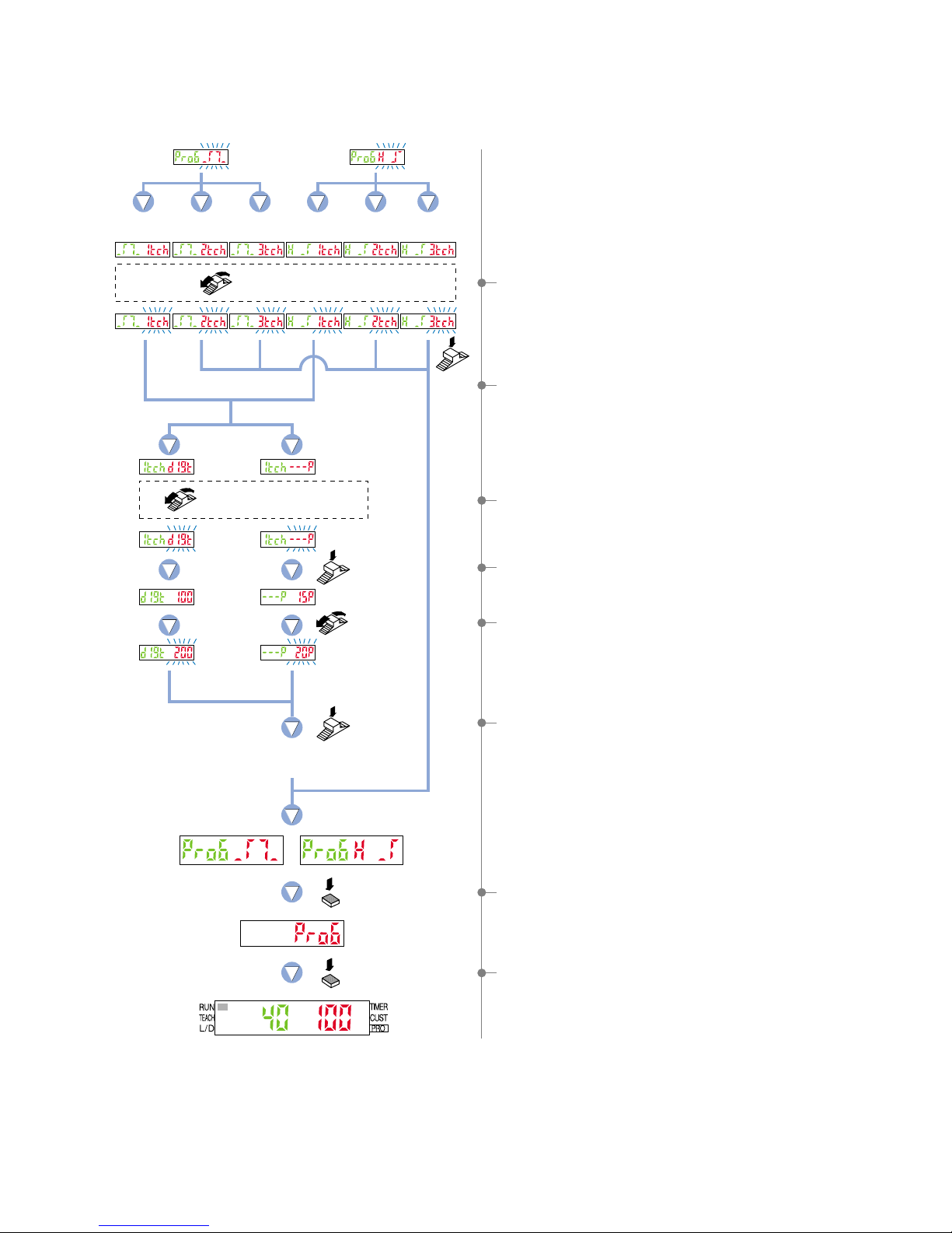
Turn the
Jog switch.
1-level
teaching
Press the
Jog switch.
The digital display will quickly
blink to confirm the setting.
2-level
teaching
2-level
teaching
3-level
teaching
3-level
teaching
1-level
teaching
digit %
Press the
Jog switch.
Select teaching method
by turning the Jog switch.
Press the
Jog switch.
Press the
MODE key once.
Press the
MODE key once.
Select the display units
by turning the Jog switch.
8If the [Jog switch] is turned, the teaching method (red) will
blink.
0Turn the [Jog switch] to select the display units.
(1-level teaching only)
BTurn the [Jog switch] to set the shift amount.
(1-level teaching only)
CIf the [Jog switch] is pressed, the shift amount setting value
(red) will quickly blink, confirming the setting.
DIf the [MODE key] is pressed once, the amplifier will return to
‘PRO6 mode’.
EPress the [MODE key] once, the amplifier will return to ‘RUN
mode’ (normal sensing operation).
9If the [Jog switch] is pressed, the teaching method will be
confirmed.
For 1-level teaching, continue by selecting the shift amount.
AIf the [Jog switch] is pressed, the display units will be
confirmed.
(1-level teaching only)
54

10-3. Output 2 Sensing Mode Settings
Output 2 can only be set to normal mode.
Press the MODE key for 2 seconds or more to make the Select 2 indicator illuminate beforehand.
Press the
MODE key 5 times.
Press the
MODE key once.
Press the
MODE key once.
The digital display will quickly
blink to confirm the setting.
Press the
Jog switch.
Press the
Jog switch.
Normal mode Output OFF
Select sensing mode
by turning the Jog switch.
Turn the Jog switch 6 times
toward the ‘
Ⳮ’ direction.
1Press the [MODE key] 5 times to select ‘PRO mode’.
2Turn the [Jog switch] 6 times toward the ‘Ⳮ’ direction, to
select ‘PRO6 mode’.
5If the [Jog switch] is pressed, sensing mode (red) will quickly
blink on the digital display, confirming the sensing mode.
6If the [MODE key] is pressed once, the amplifier will return to
‘PRO6 mode’.
7Press the [MODE key] once, the amplifier will return to ‘RUN
mode’ (normal sensing operation).
3If the [Jog switch] is pressed, the current setting (red) will be
displayed.
* The factory setting is ‘normal mode’.
4Turn the [Jog switch], the sensing mode (red) will blink on
the digital display.
Select from either ‘normal mode’ or ‘output OFF’.
55

The ‘key lock function’ prevents operators from changing the sensor settings by mistake.
Keep the Jog switch and
the MODE key pressed
for 3 sec. or more at the
same time.
Keep the Jog switch and
the MODE key pressed
for 3 sec. or more at the
same time.
Others
11-1. Key Lock Function
11
Lock engaged
Lock disengaged
1
Keep the [MODE key] and the [Jog switch] pressed for 3 sec.
or more at the same time in ‘RUN mode’ condition.
5‘ ’ will be displayed, and the key lock function will
be set to OFF.
4To disengage the lock function, keep the [MODE key] and
the [Jog switch] pressed for 3 sec. or more at the same time
once again.
3Key operations will be locked.
2‘ ’ will be displayed, and the key lock function will be
set to ON.
56
 Loading...