

Sunx GA-311, GH-2SE, GH-8SE, GH-3SE, GH-F8SE Instruction Manual
INSTRUCTION MANUAL
Amplifier-separated Type
Inductive Proximity Sensor
GA-311
Amplifier
GH-غSE
Sensor head
Thank you very much for using SUNX products. Please read this
Instruction Manual carefully and thoroughly for the correct and optimum
use of this product. Kindly keep this manual in a convenient place for quick
reference.
٨
٨
Never use this product as a sensing device for
personnel protection.
In case of using sensing devices for personnel
protection, use products which meet standards, such
as OSHA, ANSI or IEC etc., for personnel protection
applicable in each region or country.
WARNING
SPECIFICATIONS
1
Cable (Note 4)
Connector attached oil resistant high frequency coaxial cable, 3m long
[Spatter resistant cable for GH-F8SE (Outer shield: Fluorine resin)]
Enclosure:
SUS303
Sensing part:
PVC
Enclosure:
SUS303
Sensing part:
ABS
Enclosure:
SUS303
Sensing part:
PAR
Enclosure:
SUS303
Sensing part:
ABS
Enclosure:
SUS303
Sensing part:
Fluorine resin
Material
Temp. characteristic
(Note 3)
Within r5%Within r7% Within r4%
-10 to +60, Storage: -20 to +70Ambient temperature
IP50 (IEC)
IP67 (IEC), IP67g (JEM)Protection
0.04mm or less
0.07mm or less
0.05mm or lessHysteresis (Note 2)
Iron 1010t1mm
Stable sensing range
(Note 1)
0 to 0.8mm0 to 0.6mm 0 to 2.0mm0 to 1.0mm
Max. operation distance
(Note 1)
1.8mm1.2mm 4.0mm2.4mm
GH-3SE GH-F8SEGH-2SE GH-8SEGH-5SE
Spatter-resistant type
Cylindrical type
GA-311Applicable amplifier
Model No.
Item
Type
Iron 55t1mm
Standard sensing object
35 to 85% RH, Storage: 35 to 85% RH
Ambient humidity
15g approx.
35g
approx.
40g
approx.
55g
approx.
Weight
٨ Sensor head
Notes: 1)
2)
3)
4)
The stable sensing range represents the sensing range for which the sensor
can satisfy all the given specifications with the standard sensing object.
The maximum operation distance represents the maximum distance for
which the sensor can detect at +20 constant ambient temperature.
Usage within the stable sensing range is recommended for accurate
sensing applications.
Value is given for the stable sensing range.
The value represents the variation in the operation distance, that has been
set within the stable sensing range at +20, for an ambient temperature
drift from 0 to +55. (The value is for sensor head on its own.)
The length of the sensor head cable cannot be changed.
Notes: 1)
2)
3)
50mA, if five, or more, amplifiers are connected in cascade.
The value represents the variation in the operation distance, that has been
set within the stable sensing range at +20, for an ambient temperature
drift from 0 to +55. (The value is for amplifier on its own.)
The cable for amplifier connection is not supplied as an accessory. Make
sure to use the optional quick-connection cable given below.
Main cable (3-core): CN-73-C1 (cable length 1m), CN-73-C2 (cable length 2m)
CN-73-C5 (cable length 5m)
Sub-cable (1-core) : CN-71-C1 (cable length 1m), CN-71-C2 (cable length 2m)
CN-71-C5 (cable length 5m)
25mA or lessCurrent consumption
12 to 24V DCr10 %ޓRipple P-P10 % or lessSupply voltage
Type
Item
GA-311
Output
NPN open-collector transistor
Maximum sink current: 100mA
Applied voltage: 30V DC or less (between output and 0V)
Residual voltage: 1V or less [at 100mA (Note 1) sink current]
18-turn potensiometer Sensitivity adjuster
Orange LED (lights up when the output is ON)Operation indicator
Max. response frequency
3.3kHz
Normally open / closed Selectable with the operation mode switchOutput operation
Incorporated
Short-circuit protection
Red LED (lights up when the sensor head is disconnected or mis-contacted)
Disconnection alarm indicator
Ambient temperature
-10 to +60 (if 4 to 7 units are connected in cascade: -10 to +50,
if 8 to 16 units are connected in cascade: -10 to +45) (No dew condensation or icing allowed), Storage: -20 to +70
Temp. characteristic
(Note 2)
Within r5%
35 to 85% RH, Storage: 35 to 85% RHAmbient humidity
Enclosure: Heat-resistant ABS, Case cover: Polycarbonate
Material
15g approx.
Weight
٨ Amplifier
CAUTIONS
2
٨
٨
٨
٨
٨
٨
٨
٨
٨
٨
٨
٨
٨
٨
٨
Make sure that the power supply is off while wiring or adding the units.
Take care that wrong wiring will damage the sensor.
Verify that the supply voltage variation is within the rating.
In case noise generating equipment (switching regulator, inverter motor,
etc.) is used in the vicinity of this product, connect the frame ground
(F.G.) terminal of the equipment to an actual ground.
If power is supplied from a commercial switching regulator, ensure that
the frame ground (F.G.) terminal of the power supply is connected to an
actual ground.
Do not use during the initial transient time (0.5 sec.) after the power
supply is switched on.
Do not run the wires together with high-voltage lines or power lines or put
them in the same raceway. This can cause malfunction due to induction.
Be sure to use the optional quick-connection cable for amplifier
connection. Furthermore, extension up to 100m (50m: 5 to 8 units are
connected in cascade, 20m: 9 to 16 units are connected in cascade) is
possible with 0.3mm
2
or more, cable. However, in order to reduce noise,
make the wiring as short as possible.
Take care that when the cable is extended, the residual voltage rises.
Do not shorten or lengthen the sensor head cable.
This sensor is suitable for indoor use only.
Do not use the sensor at places having intense vibrations, as this can
cause malfunction.
Take care that the sensor does not come in direct contact with water, oil,
grease, organic solvents, such as, thinner etc., or strong acid, and alkaline.
Make sure that the sensing end is not covered with metal dust, scrap or
spatter. It will result in malfunction.
Take care that stress by forcible bending or pulling is not applied directly
to the sensor head cable joint.
MOUNTING
3
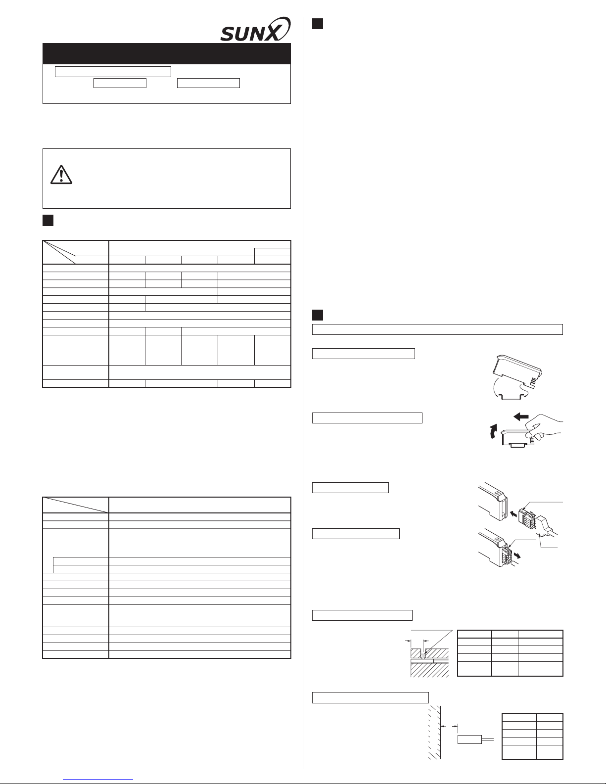
Be sure to use a sensor head and amplifier as a set.
Disconnection method
Ԙ
Pressing the projection on the sensor
head connector, pull out the connector.
Note:
Take care that if the connector is pulled out without pressing the projection, the projection may break. Do not use a sensor head connector whose projection has broken. Furthermore, do not pull by holding the cable, as this can cause a cable-break.
Connection method
ԘԙInsert the the sensor head connector into
the connector inlet till a click is felt.
Fit the cover on the connector.
٨
Connection of sensor head
Ԙ
Sensor head
connector part
Cover
ԙ
Projection
ԘԙFit the rear part of the mounting section of the
amplifier on a 35mm width DIN rail.
Press down the rear part of the mounting section
of the unit on the 35mm width DIN rail and fit the
front part of the mounting section to the DIN rail.
How to mount the amplifier
Take care that if the front part is lifted without pushing the amplifier forward, the
hook on the rear portion of the mounting section is likely to break.
Note:
How to remove the amplifier
ԘԙPush the amplifier forward.
Lift up the front part of the amplifier to remove it.
٨
Mounting of amplifier
Ԙ
35mm width DIN rail
ԙ
Ԙ
ԙ
٨ Mounting of sensor head
Do not tighten it with excessive strength.Note:
The tightening torque
for mounting should be
as given right.
Furthermore, be sure
to use a set screw with
a cup-point end.
0.17N㨯m
4 or more
0.78N㨯m
GH-3SE
5 or more
0.59N㨯m
GH-5SE
5 or more
GH-8SE
GH-F8SE
Model No.
Amm
Tightening torque
3 or more
0.17N㨯mGH-2SE
Set screw (M3)
(Cup-point end)
A
Mounting with a set screw
Influence of surrounding metal
٨ The surrounding metal
will affect the sensing
performance. Keep the
minimum distance
specified in the table
right.
4GH-3SE
5GH-5SE
9
GH-8SE
GH-F8SE
Model No.
Bmm
3
GH-2SE
B
Background metal
Phone: 800.894.0412 - Fax: 888.723.4773 - Web: www.clrwtr.com - Email: info@clrwtr.com
CONNECTION
4
Make sure that the power supply is off while connecting / disconnecting the
quick-connection cable.
Connection method
Disconnection method
Note: Take care that if the connector is pulled out without pressing the
projection, the projection may break. Do not use a quick-connection cable
whose projection has broken.
Furthermore, do not pull by holding the cable, as this can cause a cable-break.
Ԙ Pressing the projection at the top of the
quick-connection cable connector, pull out
the connector.
Projection
ԘԙHolding the connector of the quick-connec-
tion cable, align its projection with the
groove at the top portion of the amplifier
connector.
Insert the connector till a click is felt.
Groove
Projection
Quick-connection cable
٨Sensing range
The sensing range is specified for the standard sensing object. With a
non-ferrous metal, the sensing range is obtained by multiplying with the
correction coefficient specified below.
Note: The sensing range also changes if the sensing object is plated.
Correction coefficient
Aluminum
Brass
Stainless steel
(SUS304)
Model No.
1111
0.68 approx.
0.51 approx.
0.53 approx.
0.69 approx.
0.39 approx.
0.41 approx.
0.64 approx.
0.32 approx.
0.37 approx.
0.55 approx.
0.33 approx.
0.35 approx.
GH-8SE
GH-F8SE
GH-2SE GH-3SE GH-5SE
Metal
Iron
٨Mutual interference
When two or more sensors are installed in parallel or face to face, keep the
minimum separation distance specified below to avoid mutual interference.
15
20
26
D (mm)
10
20GH-3SE
25GH-5SE
40
GH-8SE
GH-F8SE
Model No.
C (mm)
15
GH-2SE
Face to face mountingCParallel mounting
D
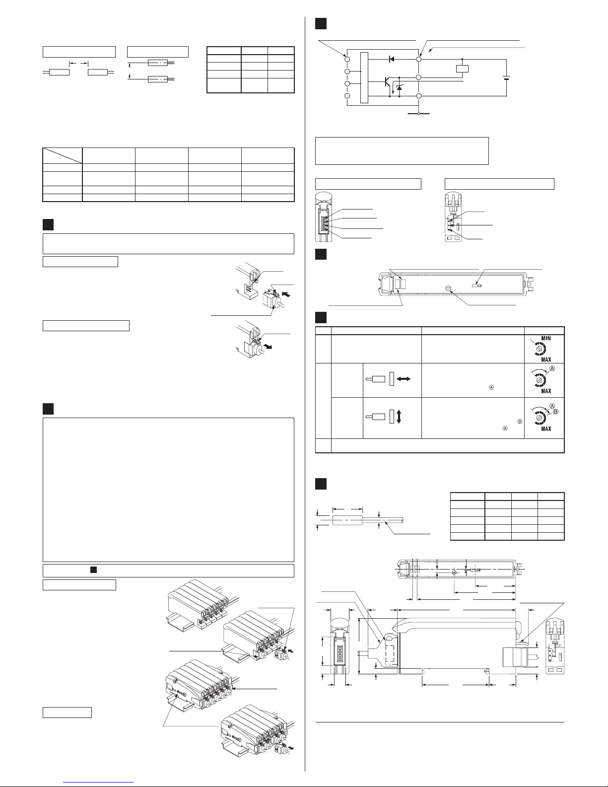
I/O DIAGRAMS
6
Note: The quick-connection cable does not have +V(Blown) and 0V(Blue). The
supply voltage is supplied through the main cable connector.
Symbols... D
Z
D
Tr
: Reverse supply polarity protection diode
: Surge absorption zener diode
: NPN output transistor
D
100mA max.
1
2
3
1
4
2
3
ZD
Tr
Connector pin No. for power supply side
Connector pin No. for the sensor head side
Load
(Brown) +V (Note)
(Black) Output
+
12 to 24V DC
r10%
(Blue) 0V (Note)
User's circuit
Internal circuit
Color code of quick-connection cable
Not used
Signal wire
Shielded wire
Not used
Sensor head side connector
Power supply side connector
٨
Terminal arrangement diagram
Ԙ㧗V
ԚOutput
ԙ0V
ԘNot used
ԙSignal wire
ԛNot used
ԚShielded wire
٨
٨
٨
٨
٨
٨
٨
Make sure that the power is off while cascading/removing the amplifiers.
Be sure to check the allowable ambient temperature, as it depends on
the number of amplifiers connected in cascade.
In case two, or more, amplifiers are connected in cascade, make sure to
mount them on a DIN rail.
When the amplifiers move on the DIN rail depending on the attaching
condition, fitting them between the optional end plates (MS-DIN-E)
mounted at the two ends.
When connecting in cascade, mount the amplifiers close to each other, fitting
them between the optional end plates (MS-DIN-E) mounted at the two ends.
When connecting more than two amplifiers in cascade, use the sub cable
(CN-71-Cغ) as the quick-connection cable for the second amplifier onwards.
This product does not incorporate the communication function When
this product used by cascading along with other than this product,
mount at the either side of the cascaded products.
CASCADING UNITS
5
Refer to the ' MOUNTING' for mounting/dismantling the amplifiers.
3
Cascading method
Main cable
(CN-73-Cغ) (optional)
Ԙ
ԙ
Ԛ
ԛ
Mount the amplifiers, one by
one, on the 35mm width DIN
and set them close to each
other without any gap between
them.
Connect the quick-connection
cables to the amplifiers.
Mount the end plate (MS-DIN-E)
(optional) at both ends to hold
the units between their flat sides.
Tighten the screws to fix the
end plates (MS-DIN-E)
Sub-cable
(CN-71-Cغ)
(optional)
End plate
(MS-DIN-E) (optional)
End plate
(MS-DIN-E)
(optional)
Dismantling
Ԙ
ԙ
Pressing the projection at the top
of the quick connection cable
connector, pull out the connector.
Remove the amplifiers.
SENSITIVITY ADJUSTMENT
8
Note: Use a flathead screwdriver (please arrange separately) to turn the adjuster
slowly. Turning with excessive strength will cause damage to the adjuster.
Step Sensing condition Adjustment
Ԙ
Set the operation mode switch to
NORM. (Initial setting)
Turn the sensitivity adjuster fully counterclockwise. (Minimum sensitivity)
Sensitivity adjuster
Approach
along sensing axis
Approach
perpendicular to sensing axis
Ԛ
Select the operation mode as per your application.
(NORM.: Normally open, INV.: Normally closed)
ԙ
Place the sensing object within the
stable sensing range.
Turn the sensitivity adjuster clockwise
and set it at the point where the
operation indicator (orange) lights up.
Place the sensing object within the
stable sensing range.
Turn the sensitivity adjuster clockwise,
and set it at the optimum sensing point
which is a little beyond the point where
the operation indicator (orange) lights up.
Sensing object
Sensor
head
Movement
direction
Sensing object
Sensor
head
Movement
direction
PART DESCRIPTION
7
Operation indicator (Orange)
Disconnection alarm indicator (Red) Operation mode switch
Sensitivity adjuster
DIMENSIONS (Unit: mm)
9
٨ GH-غSE / Sensor head
A
B
C
Cable 3m long
15
15
15
B
12
Ǿ3.8GH-3SE
Ǿ5.4GH-5SE
GH-8SE Ǿ8.0
15
Ǿ2.5
Ǿ2.5
Ǿ2.5
C
Ǿ1.6
Ǿ2.65GH-F8SE Ǿ8.0
Model No.
A
Ǿ2.8
GH-2SE
Note: The side view is with the sensor head connector and the quick-connection
cable.
٨ GA-311 / Amplifier
1.9 0.4
21.95
33.5
53.7
2.5
4.65
15.55
10
6.3
64.5(16) (7)
36.5 14.5
30.5
3 3.95
10.5
Sensor head
connector
Connector cover
Sensor circuit
Phone: 800.894.0412 - Fax: 888.723.4773 - Web: www.clrwtr.com - Email: info@clrwtr.com
 Loading...