

INSTRUCTION MANUAL
Auto-setting Fiber Sensor
FX-A1 Series
Thank you very much for using SUNX products. Please read this Instruction Manual
carefully and thoroughly for the correct and optimum use of this product. Kindly keep
this manual in a convenient place for quick reference.
٨٨Never use this product as a sensing device for personnel protection.
In case of using sensing devices for personnel protection, use
WARNING
1
SPECIFICATIONS
Item
Supply voltage
Current consumption
Sensing output
Output operation
Short-circuit protection
Self-diagnosis output
Output operation
Short-circuit protection
Emission frequency 1
Emission frequency 2
Response
time
Emission frequency 3
Sensitivity setting
Timer function
Interference prevention function
Ambient temperature
Ambient humidity
Emitting element
Material
Cable
Weight
Accessory
Note: For the plug-in connector type, add suffix 'J' at the end of the model No.
Model No.: FX-A1J, FX-A1GJ, FX-A1PJ
For the cable length 5m type, add suffix '-C5' at the end of the model No. (only NPN output type)
Model No.: FX-A1-C5, FX-A1G-C5
2
CAUTIONS
٨
Make sure to carry out the wiring in the power supply off condition.
٨
Verify that the supply voltage variation is within the rating.
In case noise generating equipment (switching regulator, inverter motor, etc.) is used in the vicinity
٨
of this product, connect the frame ground (F.G.) terminal of the equipment to an actual ground.
If power is supplied from a commercial switching regulator, ensure that the frame
٨
ground (F.G.) terminal of the power supply is connected to an actual ground.
Do not use during the initial transient time (0.5 sec.) after the power supply is switched on.
٨
The self-diagnosis output is not incorporated with a short-circuit protection. Do not
٨
connect it directly to a power supply or a capacitive load.
٨
Do not run the wires together with high-voltage lines or power lines or put them in
the same raceway. This can cause malfunction due to induction.
٨
Extension up to total 100m is possible with a 0.3mm
order to reduce noise, make the wiring as short as possible.
This sensor is suitable for indoor use only.
٨
Avoid dust, dirt, and steam.
٨
Take care that the product does not come in direct contact with organic solvents, such as, thinner, etc.
٨
This sensor cannot be used in an environment containing inflammable or explosive gases.
٨
Never disassemble or modify the sensor.
٨
3
MOUNTING
How to mount the amplifier
ԘԙFit the rear part of the mounting section of the amplifier
on the attached amplifier mounting bracket (MS-DIN-2)
or a 35mm width DIN rail.
Press down the rear part of the mounting section of the
unit on the attached amplifier mounting bracket
(MS-DIN-2) or a 35mm width DIN rail and fit the front
part of the mounting section to the attached amplifier
mounting bracket (MS-DIN-2) or a 35mm width DIN rail.
How to remove the amplifier
ԘԙPush the amplifier forward.
Lift up the front part of the amplifier to remove it.
Take care that if the front part is lifted without pushing the
Note:
amplifier forward, the hook on the rear portion of the mounting
section is likely to break.
products which meet standards, such as OSHA, ANSI or IEC etc.,
for personnel protection applicable in each region or country.
Type
Model No.
NPN output
Red LED type Red LED type
FX-A1
NPN open-collector transistor
Maximum sink current: 100mA
Applied voltage: 30V DC or less
(between sensing output and 0V)
Residual voltage:
1V or less (at 100mA sink current)
0.4V or less (at 16mA sink current)
NPN open-collector transistor
Maximum sink current: 50mA
Applied voltage: 30V DC or less
(between self-diagnosis output and 0V)
Residual voltage:
1V or less (at 50mA sink current)
0.4V or less (at 16mA sink current)
Approx. 40ms fixed OFF-delay timer (switchable, either effective or ineffective)
Incorporated (up to three sets of fibers can be mounted adjacently)
-10 to +50 (No dew condensation or icing allowed), Storage: -20 to +70
Red LED (modulated)
Enclosure: Heat-resistant ABS, Enclosure cover: Polycarbonate
Green LED type
FX-A1G
12 to 24V DCr10%˴Ripple P-P 10% or less
Selectable, either Light-ON or Dark-ON, with jog switch
2-level teaching / Limit teaching / Full auto-teaching
35 to 85% RH, Storage: 35 to 85% RH
0.2mm
MS-DIN-2 (Amplifier mounting bracket): 1 No.
50mA or less
PNP open-collector transistor
Applied voltage: 30V DC or less
Residual voltage:
Incorporated
PNP open-collector transistor
Maximum source current: 50mA
Applied voltage: 30V DC or less
Residual voltage:
ON in unstable sensing condition
0.5ms or less
0.65ms or less
0.75ms or less
Green LED (modulated)
2
4-core cabtyre cable, 2m long
70g approx.
PNP output
FX-A1P
Maximum source current: 100mA
(between sensing output and +V)
1V or less (at 100mA source current)
0.4V or less (at 16mA source current)
(between self-diagnosis output and +V)
1V or less (at 50mA source current)
0.4V or less (at 16mA source current)
Red LED (modulated)
2
, or more, cable. However, in
ԙ
Attached amplifier mounting
bracket or 35mm width DIN rail
Ԙ
ԙ
Ԙ
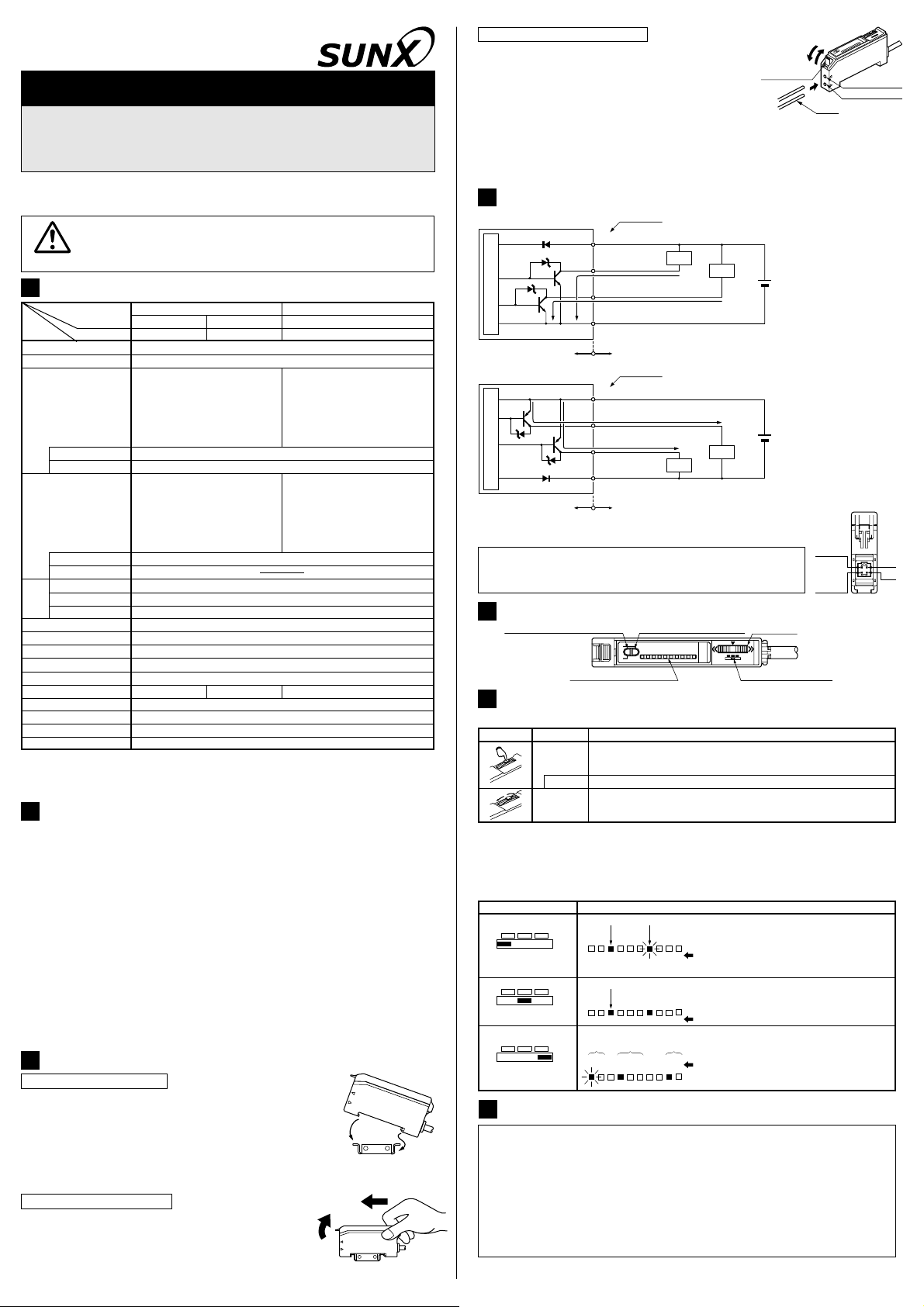
How to connect the fiber cables
Ԙ
Snap the fiber lock lever down.
ԙ
Insert the fiber cables slowly into the inlets until
they stop. (Note 1)
Ԛ
Return the fiber lock lever to the original position,
Fiber lock
lever
till it stops.
Notes: 1)2)In case the fiber cables are not inserted to a position where they stop, the sensing range reduces.
However, in case of a flexible fiber, take care that it may bend inside the amplifier, during insertion.
With the coaxial reflective type fiber, such as, FD-G4 or FD-FM2, insert the single-core
fiber cable into the beam-emitting inlet and the multi-core fiber cable into the beam-receiving inlet. If they are inserted in reverse, the sensing accuracy will deteriorate.
4
I/O CIRCUIT DIAGRAMS
٨ NPN output type
D
1
Z
D1
T
Z
D2
Sensor circuit
r1
T
r2
PNP output type٨
T
r3
T
r4
Z
D3
Sensor circuit
Z
D4
D
2
Note: Use the optional cable with a connector for the plug-in connector type.
Model No.: CN-54-C2 (cable length 2m), CN-54-C5 (cable length 5m)
Symbols... D1, D2
5
PART DESCRIPTION
Operation indicator (Orange)
6
JOG SWITCH & LEVEL INDICATOR FUNCTION
: Reverse supply polarity protection diode
ZD1, ZD2, ZD3, ZD4: Surge absorption zener diode
: NPN output transistor
1, Tr2
Tr
: PNP output transistor
Tr 3, Tr4
Level indicators (Green)
Color code
(Brown) +V
(Black)
Sensing output
(Orange) Self-diagnosis output
(Blue) 0V
Users' circuitInternal circuit
Color code
(Brown) +V
(Black)
(Orange)
Self-diagnosis output
(Blue) 0V
Users' circuitInternal circuit
Load
100mA max.
50mA max.
100mA max.
Sensing output
50mA max.
Load
Stability indicator (Green)
Load
+
-
+
-
Load
Jog switch
Mode selection switch
12 to 24V DC
r10%
12 to 24V DC
r10%
Ԛ
Ԙ
Beam-emitting part
Beam-receiving part
ԙ
Fiber
Connector pin
position
Sensing
output
Selfdiagnosis
output
+V
0V
٨ Functions of jog switch
Jog switch Operation
Press
3 sec. or more
㧙
㧗
Tu rn
In 2-level teaching, it sets the sensitivity.
In limit teaching, it stores the incident light intensity in the object absent condition.
Each item is selected and the item or the contents of each item to be set is decided.
In full auto-teaching, it sets the sensitivity.
In limit teaching, it determines the direction of shift of the sensitivity.
It does fine adjustment of the set sensitivity.
The contents of each item are selected.
Function
٨Functions of level indicators
If the mode selection switch is set to 'SET' or 'RUN', the level indicators show the
position of the set sensitivity level. However, if the mode selection switch is set to
'MODE', the level indicators show the output operation/emission frequency/timer
settings.
Mode selection switch
SET MODE
RUN
SET MODE
RUN
SET MODE
RUN
7
SENSITIVITY SETTING
٨
When the mode selection switch is set to 'SET' or 'MODE', the sensor is
Hundreds position
L-ON
987654321
*: The sensitivity level is changed in the range 0 to 999 within the sensor.
Hundreds position
L-ON
987654321
Output
operation
L-ON
987654321
D-ON
D-ON
D-ON
Tens position
FR1
FR2
FR3
FR1
FR2
FR3
Emission
frequency
FR1
FR2
FR3
NON
NON
Timer
operation
NON
OFD
0
Set sensitivity
OFD
0
Set sensitivity
Each mode
OFD
0
Function
Sensitivity level is displayed.
Hundreds position: lights up continuously
Tens position: blinks
Units position: not shown
Sensitivity level is displayed.
Hundreds position: lights up continuously
Tens position: not shown
Units position: not shown
Each mode is displayed.
Item being set: blinks
Remaining 2 items: light up
continuously
more susceptible to extraneous light. Hence, when sensing objects, ensure to set
the mode selection switch to 'RUN'.
٨
When the mode selection switch is changed from 'SET' to 'RUN' or from 'MODE'
to 'RUN', the set sensitivity or the contents of each mode setting are stored in an
EEPROM. Since the EEPROM has a life time, the sensitivity setting cannot be
done for more than 100,000 times.
Do not move or bend the fiber cable after the sensitivity setting. Detection may
٨
become unstable.
In case of 2-level teaching
٨
This is the method of setting the sensitivity by teaching two levels, corresponding to the
object present and object absent conditions. Normally, setting is done as given below.
Level indicators OperationStep
Ԙ
ԙ
987654321
987654321
Ԛ
987654321
ԛ
Ԝ
987654321
ԝ
Note: If the jog switch is pressed continuously for 3 sec., or more, full auto-teaching is done.
Also, if the mode selection switch is changed to 'RUN' while level indicators '4' and '5' are
blinking, the incident light intensity taught at Step Ԛ is not recorded.
Set the fiber within the sensing range.
Set the mode selection switch to 'SET'.
0
The present sensitivity setting is displayed.
Press the jog switch in the object present condition. The level indicators
0
'3' and '6' blink.
Release the jog switch within 3 sec. The level indicators '4' and '5' blink and
the incident light intensity in the object present condition is read. (Note)
0
The jog switch is pressed in the object absent condition.
The stability indicator (green) lights up and the sensitivity level is set at the
middle value of the incident light intensity levels in the object present and object
absent conditions. The sensitivity level is then displayed on the level indicators.
Hundreds position: lights up continuously, Tens position: blinks,
0
Units position: not shown
Example: The level indicators in the figure on the left show that the
sensitivity level is in the range 720 to 729.
Set the mode selection switch to 'RUN'.
The sensitivity level does not change even if the jog switch is operated.
<Procedure for maximum sensitivity setting>
Set the mode selection switch to 'SET'.
Ԙ
Press the jog switch in the condition when there is no object or background body.
ԙ
The level indicators '4' and '5' blink after receiving the teaching.
Ԛ
ԛ
Once again, press the jog switch in the condition when there is no object or background body.
Ԝ
The level indicator '9' blinks.
ԝ
Set the mode selection switch to 'RUN'.
Note: Please take care that, if the sensor is set to max. sensitivity, it becomes weak against
extraneous light, noise and optical interference.
In case of fine adjustment
Ԙ
ԙ
Ԛ
Level indicators OperationStep
987654321
987654321
987654321
987654321
987654321
Set the mode selection switch to 'SET'.
0
The present sensitivity setting is displayed.
0
In case the sensitivity is to be increased, turn the jog switch a little to
the '+' side to increase the sensitivity slowly. If the jog switch is turned
0
or
fully to the '+' side, the sensitivity increases rapidly.
In case the sensitivity is to be decreased, turn the jog switch a little to
-
' side to decrease the sensitivity slowly. If the jog switch is turned
the '
0
fully to the '
0
Set the mode selection switch to 'RUN'.
The sensitivity level does not change even if the jog switch is operated.
-
' side, the sensitivity decreases rapidly.
In case of limit teaching
٨ This is the method of setting the sensitivity by teaching only the object absent
condition (incident light stable condition). This is used for detection in presence of a
background body or for detection of small objects.
Level indicatorsStep
Ԙ
ԙ
987654321
987654321
Ԛ
987654321
ԛ
987654321
Ԝ
Note: If the jog switch is pressed continuously for 3 sec., or more, full auto-teaching is done.
Also, if the mode selection switch is changed to 'RUN' while level indicators '4' and '5' are
blinking, the incident light intensity taught at Step Ԛ is not recorded.
Set the fiber within the sensing range.
Set the mode selection switch to 'SET'.
0
The present sensitivity setting is displayed.
Press the jog switch in the object absent condition. The level indicators
0
'3' and '6' blink.
Release the jog switch within 3 sec. The level indicators '4' and '5' blink and
the incident light intensity in the object present condition is read. (Note)
0
Turn the jog switch to either the '+' or the '-' side.
0
Example: The level indicators in the figure on the left show that the
Set the mode selection switch to 'RUN'.
The sensitivity is increased
'+' side:
by 15% approx. with respect
to that set at Ԛ. Used in
case of thru-beam type fiber.
-
' side:
The sensitivity is decreased
'
by 15% approx. with respect
to that set at Ԛ. Used in
case of reflective type fiber.
sensitivity level is in the range 720 to 729.
The sensitivity level does not change even if the jog switch is operated.
Operation
High
100%
Sensitivity
level
Low
ON
OFF
Turn to '+' side
Sensitivity
level
Sensitivity
level with
object absent
Sensitivity
level
OFF
15%
15%
ON
0
Turn to '-' side
In case of full auto-teaching
٨ Full auto-teaching is used when it is desired to set the sensitivity without stopping
the assembly line, with the object in the moving condition.
Level indicators OperationStep
Ԙ
ԙ
Ԛ
ԛ
Ԝ
987654321
987654321
987654321
Set the fiber within the sensing range.
Set the mode selection switch to 'SET'.
0
The present sensitivity setting is displayed.
Press the jog switch continuously for 3 sec., or more, with the object
moving on the assembly line.
When the jog switch is pressed, the level indicators '3' and '6' blink and
0
when it is pressed continuously for 3 sec., or more, they start blinking
rapidly. Then, release the jog switch when the object has passed.
The stability indicator (green) lights up and the sensitivity level is set at the
middle value of the incident light intensity levels in the object present and object
absent conditions. The sensitivity level is then displayed on the level indicators.
Hundreds position: lights up continuously, Tens position: blinks,
0
Units position: not shown
Example: The level indicators in the figure on the left show that the
sensitivity level is in the range 720 to 729.
Set the mode selection switch to 'RUN'.
The sensitivity level does not change even if the jog switch is operated.
8
SETTING OF EACH MODE
Level indicators DescriptionStep
Ԙ
ԙ
The mode being set blinks.
Ԛ
Output oper-
ation setting
ԛ
Ԝ
Emission fre-
quency setting
ԝ
Ԟ
Timer oper-
ation setting
ԟ
Ԡ
L-ON
L-ON
L-ON
L-ON
D-ON
D-ON
D-ON
D-ON
FR1
FR2
FR1
FR2
FR1
FR2
FR1
FR2
Set the mode selection switch to 'MODE'.
Turn the jog switch to either the '+' or the '-' side.
FR3
NON
OFD
L-ON (Light-ON) D-ON (Dark-ON)
Press the jog switch at the output operation desired to be set.
Turn the jog switch to either the '+' or the '-' side.
FR3
FR1
NON
OFD
(Emission frequency 1)
Press the jog switch at the emission frequency desired to be set.
Turn the jog switch to either the '+' or the '
FR3
FR3
NON
NON
OFD
(without timer)
Press the jog switch at the timer operation desired to be set.
NON
OFD
Back to ԙ.
Set the mode selection switch to 'RUN' after finishing the settings.
+
FR2
(Emission frequency 2)
+
OFD
(approx. 40ms fixed OFF-delay timer)
+
-
FR3
(Emission frequency 3)
+
-
' side.
In case only a part of the settings are to be changed, set the mode selection switch to 'RUN', at
the appropriate time, in the middle of the above procedure to make only the required changes.
9
TIMER FUNCTION
٨
FX-A1 series incorporate an approx. 40ms fixed OFF-delay timer. Since the output is
extended by a fixed period, it is useful when the connected device has a slow response
time or when small objects are being sensed and the output signal width is small.
Please refer to ' SETTING OF EACH MODE' for the setting method.
8
<Time chart>
Timer
operation
Normal
OFF-delay
timer
Output
operation
Light-ON
Dark-ON
Light-ON
Dark-ON
Sensing
condition
TT T
T
Light
Dark
ON
OFF
ON
OFF
ON
OFF
ON
OFF
Timer period: T = 40ms approx.
10
INTERFERENCE PREVENTION FUNCTION
٨
Since the FX-A1 series incorporate an interference prevention function, up to 3 sets of
fibers can be mounted close to each other by setting different emission frequencies.
Further, close mounting is also possible along with
fibers which are fitted to the fiber sensor amplifiers,
FX-D1 series and FX-M1 series.
Please refer to ' SETTING OF EACH MODE' for the
8
setting method.
However, note that the response time varies with the
Emission
frequency
1
2
3
Response
time
0.5ms or less
0.65ms or less
0.75ms or less
emission frequency as given below.
11
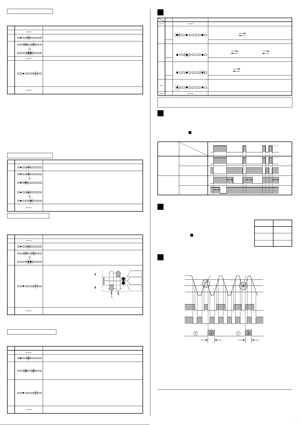
SELF-DIAGNOSIS FUNCTION
٨ This is a function which diagnoses a decrease in the incident light intensity due
to dirt or dust, or optical misalignment, and gives an output.
Insufficient beam intensity Insufficient beam interruption
Stable Light level
Sensing condition
Sensing output
threshold level
Stable Dark level
Sensing output
(Operation indicator)
(in the Light-ON mode)
Stability indicator
Self-diagnosis output
40ms approx. 40ms approx.
The self-diagnosis output transistor stays in the 'OFF' state during stable sensing.
Ԙ
When the sensing output changes, if the incident light intensity does not reach
ԙ
ON (Lights up)
OFF (Lights off)
Lights up
Lights off
ON
OFF
the stable light level or the stable dark level, the self-diagnosis output becomes
'ON'. It automatically turns 'OFF' after 40ms approx. (Emission frequency 2:
50ms approx., Emission frequency 3: 60ms approx.)
Further, the self-diagnosis output is generated at the time when the sensing
output changes from 'ON' to 'OFF' or from 'OFF' to 'ON'.
(The operation of the sensing output is not affected.)
SUNX Limited
http://www.sunx.co.jp/
Head Office
2431-1 Ushiyama-cho, Kasugai-shi, Aichi, 486-0901, Japan
Phone: +81-(0)568-33-7211 FAX: +81-(0)568-33-2631
Overseas Sales Dept.
Phone: +81-(0)568-33-7861 FAX: +81-(0)568-33-8591
PRINTED IN JAPAN
 Loading...