

INSTRUCTION MANUAL
FX-7 Series
Automatic Sensitivity Stetting Fiber SensorSlim type
Never use this product as a sensing device for personnel protection.
In case of using sensing devices for personnel protection, use
products which meet standard, such as OSHA, ANSI or IEC etc.,
for personnel protection applicable in each region or country.
WARNING
Thank you very much for using SUNX products. Please read this Instruction
Manual carefully and thoroughly for the correct and optimum use of this
product. Kindly keep this manual in a convenient place for quick reference.
Item
Supply voltage
Current consumption
Sensing output
Self-diagnosis
output
External inputs
• External synchronization input
• Emission disable input
• Remote sensitivity setting input
Response time
Timer function
Ambient temperature
Material
Accessory
NPN output
FX-7 FX-75 FX-77
12 to 24V DC ± 10%, Ripple P-P 10% or less
30mA or less
NPN open-collector transistor
• Maximum sink current: 100mA
• Applied voltage: 30V DC or less
(between sensing output and 0V)
• Residual voltage:
1.0V or less (at 100mA sink current)
0.4V or less (at 16mA sink current)
Selectable either Sensing-ON or Non-sensing-ON by the ON/OFF buttons
Incorporated
ON under unstable sensing (this signal lasts approx. 40ms) or
ON when sensing output is short-circuited (signal lasts till short-circuit is rectified) (
Note 2
)
Signal condition
High ... 4.5 to 30V, or open
Low ... 0 to 1V
Input impedance: 10kΩ
0.5ms or less ( When using interference prevention function: 0.7ms or less)
Approx. 40ms fixed off-delay timer (Selectable with timer operation selection switch) (Except for FX-75, FX-75G)
–10 to +50°C (No dew condensation or icing allowed), Storage: –20 to +70°C
35 to 85% RH, Storage: 35 to 85% RH
Enclosure: Heat-resistant ABS, Enclosure cover: Polycarbonate, Fiber lock lever: PPS
MS-DIN-2 (Amplifier mounting bracket): 1 No.
PNP output
FX-7P
Standard type
External synchronization input type
Remote sensitivity setting type
Standard type
Output operation
Output operation
Short-circuit protection
Short-circuit protection
Model
No.
Ty
pe
Red LED
Green LED
FX-7G FX-75G
FX-77G
FX-7GP
Ambient humidity
Plug-in connector type is specified by suffix ‘J’ at the end of the model number. (Standard type only)
e.g.) Plug-in connector type of FX-7 is‘FX-7J’.
The remote sensitivity setting type are in the ON state for approx. 40ms even after
accepting the remote sensitivity setting input.
Notes: 1)
2)
NPN output type
PNP open-collector transistor
• Maximum source current: 100mA
• Applied voltage: 30V DC or less
(between sensing output and +V)
• Residual voltage:
2.0V or less (at 100mA source current)
1.0V or less (at 16mA source current)
PNP output type
NPN open-collector transistor
• Maximum sink current: 50mA
• Applied voltage: 30V DC or less
(between self-diagnosis output and 0V)
• Residual voltage:
1.0V or less (at 50mA sink current)
0.4V or less (at 16mA sink current)
NPN output type
PNP open-collector transistor
• Maximum source current: 50mA
• Applied voltage: 30V DC or less
(between self-diagnosis output and +V)
• Residual voltage:
2.0V or less (at 50mA source current)
1.0V or less (at 16mA source current)
PNP output type
FX7
Fiber lock lever
Stopper
Fiber cable
1
2
3
FX7
Beam-receiving part
Beam-
emitting part
Beam-receiving part
(multi-core)
Coaxial fiber
cable
Beam-emitting part (single-core)
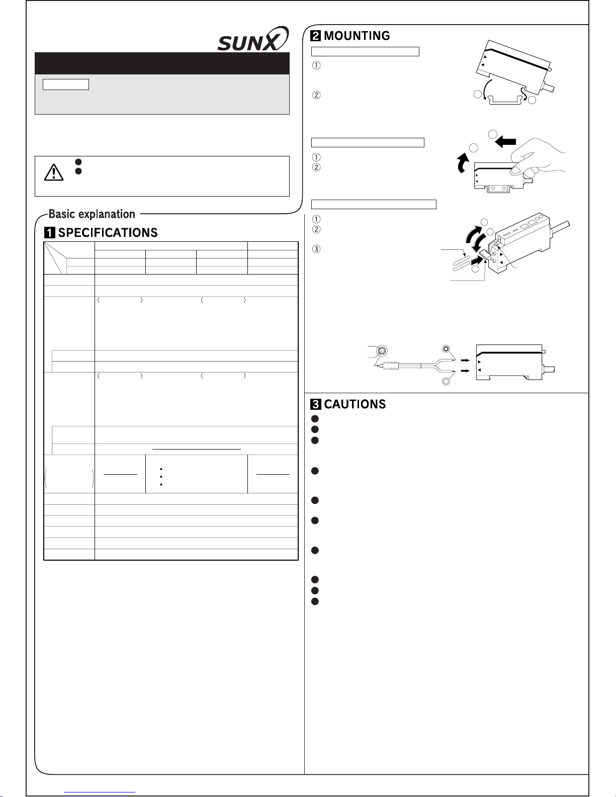
How to mount the amplifier
Fit the rear part on the attached
amplifier mounting bracket
(MS-DIN-2) or a 35mm width DIN rail.
Press down the front part of the
amplifier on the amplifier mounting
bracket (MS-DIN-2) or the DIN rail
to fit it.
How to remove the amplifier
Push the amplifier forward.
Lift up the front part of the
amplifier to remove it.
How to connect the fiber cables
Attached amplifier mounting bracket
or 35mm width DIN rail.
FX7
1
2
1
2
Snap the fiber lock lever down.
Insert fiber cables slowly into the
inlets until they stop. (Note 1)
Lock the fiber lock lever in the
original position, till you feel a
click.
With the coaxial reflective type fiber, such as, FD-G4, FD-FM2, insert the
center fiber cable (single-core) into the beam-emitting inlet and the outer fiber
cable (multi-core) into the beam-receiving inlet. If they are inserted in reverse,
the sensing accuracy will deteriorate.
Notes: 1)
2)
In case the fiber cables are not inserted to a position where they stop, the
sensing range reduces.
Make sure to carry out the wiring in the power supply off condition.
Verify that the supply voltage variation is within the rating.
Avoid dust, dirt, and steam.
Extension up to total 100m is possible with a 0.3mm2, or more, cable.
If power is supplied from a commercial switching regulator, ensure
that the frame ground (F.G.) terminal of the power supply is connected to an actual ground.
In case noise generating equipment (switching regulator, inverter
motor, etc.) is used in the vicinity of this product, connect the frame
ground (F.G.) terminal of the equipment to an actual ground.
The self-diagnosis output is not incorporated with a short-circuit
protection circuit. Do not connect it directly to a power supply or a
capacitive load.
Do not run the wires together with high voltage lines or power lines
or put them in the same raceway. This can cause malfunction due to
induction.
Do not use during the initial transient time (0.5 sec.) after the power
supply is switched on.
Take care that the product does not come in direct contact with
water, oil, grease or organic solvents, such as, thinner, etc.
Ramco Innovations
Phone 800-280-6933
www.sunxsensors.com
5V
5V
ZD2
Tr2
Tr1
ZD1
D
Sensor circuit
+
–
12 to 24V DC
± 10%
(Brown) +V
Color code
(Black) Sensing output
(Blue) 0V
(Orange) Self-diagnosis
output
Internal circuit Users' circuit
(Pink) Input 1
Load
Load
100mA
max.
50mA
max.
(Violet) Input 2
NPN output type
ZD2
Tr3
Tr4
ZD1
+
–
Sensor circuit
(Black) Sensing output
(Blue) 0V
Internal circuit Users' circuit
(Orange)
Self-diagnosis output
Load
Load
D
100mA max.
50mA
max.
PNP output type
12 to 24V DC
± 10%
(Brown) +V
Color code
Model No.
External synchronization input (ES)
Remote sensitivity setting OFF input (R.OFF)
Remote sensitivity setting ON input (R.ON)
Input 1
Input 2
FX-7(P)
FX-7G(P)
FX-75
FX-75G
FX-77
FX-77G
Emission disable input (CONT.)
Input
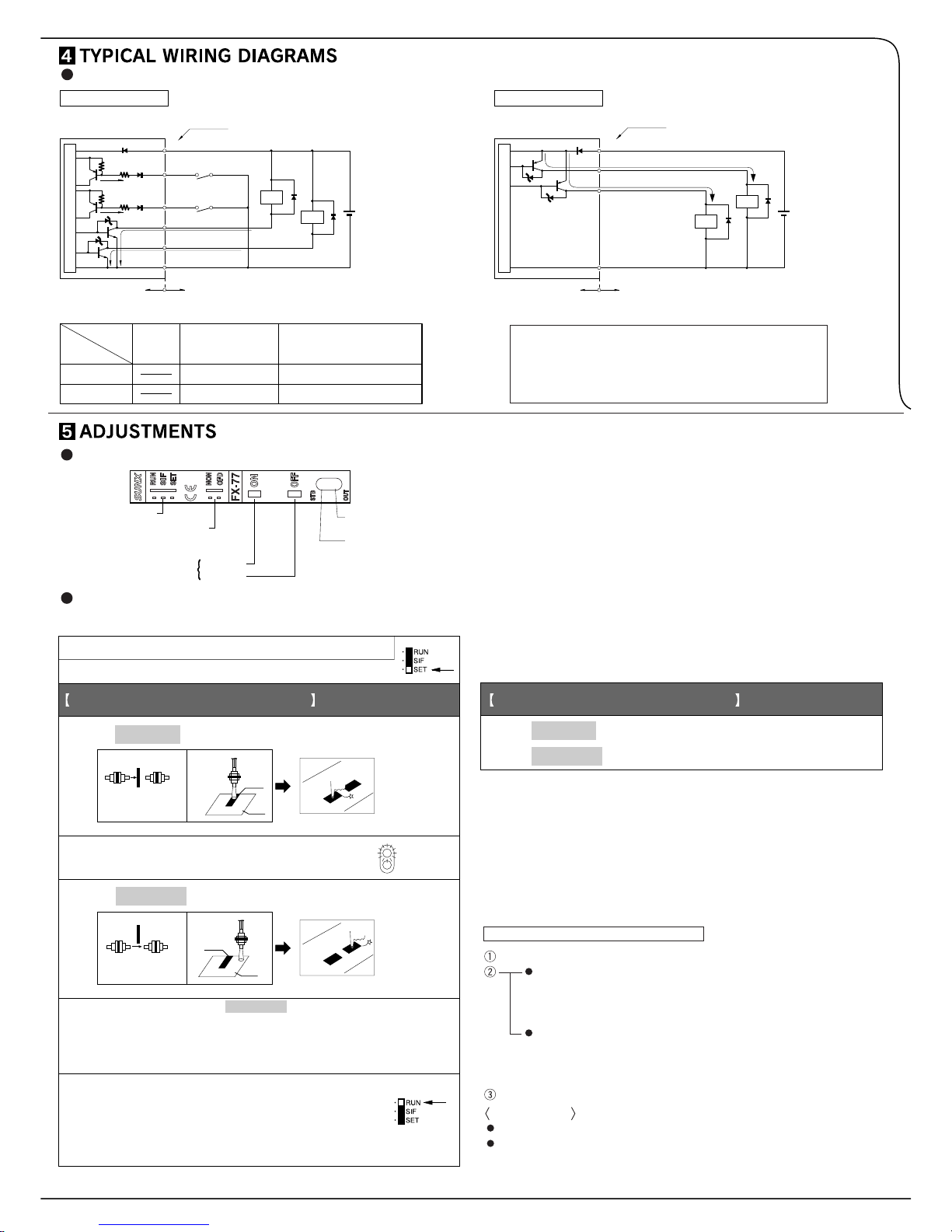
Mode selection switch
Timer operation
selection switch (Note)
Sensitivity setting button
ON button
OFF button
Operation
indicator (Red)
Stability
indicator (Green)
Mark
Base
Light
interrupted
condition
Thru-beam type
Reflective
type
Thru-beam type
Reflective
type
STB
OUT
Mark
Base
1. Place the fiber cable within the sensing range. (Note 1)
2. Set the mode selection switch to ‘SET’
3. Press ON button with the object present.
When ON state is recognized by the sensor,
stability indicator (green) will flash.
6.
Press ON button with object absent.
Press OFF button with object present.
5. Press OFF button with the object absent.
4.
For sensing output ON with object present
Light is
received
condition
7.
For sensing output ON with object absent
ON
OFF
ON
OFF
The stability indicator will flash twice if the sensitivity gap between
ON state and OFF state is sufficient and a stable detection is
possible.
The stablility indicator will flash continuously if stable detection
is not
possible. (Note 2)
Set the mode selection switch to ‘RUN’.
The sensitivity setting buttons become
ineffective. So, even if the buttons are pressed
by mistake , the registered sensitivity will remain
unchanged.
I/O circuit diagrams
Note: The designation of input wires differ depending on the model.
Note: Synchronization selection switch for FX-75, FX-75G.
Use of sensitivity setting buttons
(Common for all models)
Part description
Refer to the catalog as the sensing range differs according to the type of fiber
cable. The sensing range of the reflective type fiber cable is the value for
white non-glossy paper. The actual sensing distance differs according to the
color of the sensing object, its surface condition, etc.
The sensitivity can also be set under unstable sensing condition. But the
severe condition may affect the sensing.
The set sensitivity is stored in an EEPROM. Since the EEPROM has a
lifetime, the sensitivity setting cannot be done for more than 100,000 times.
Do not move or bend the fiber cable after the sensitivity setting. Detection
may become unstable.
Symbols ... D: Reverse supply polarity protection diode
ZD1, ZD2: Surge absorption zener diode
Tr1, Tr2: NPN output transistor
Tr3, Tr4: PNP output transistor
Set the mode selection switch to ‘SET’.
In case of Light-ON operation
In the dark condition, press the ON button and then the OFF button
successively. (or, make the remote sensitivity setting ON input and
then the OFF input Low successively.)
In case of Light-OFF operation
In the dark condition, press the OFF button and then the ON button
successively. (or, make the remote sensitivity setting OFF input and
then the ON input Low successively.)
Set the mode selection switch to ‘RUN’.
Applications
For getting a long sensing range with reflective type sensor.
For using thru-beam type sensor in an unfavorable sensing environment.
How to set the maximum sensitivity
Notes: 1)
2)
3)
4)
Ramco Innovations
Phone 800-280-6933
www.sunxsensors.com

T
T T T
Timer
operation
selection
switch
Output operation
Sensing
state
NON
OFD
NON
OFD
NormalTimer
ON in sensing
state
ON in nonsensing state
ON in sensing
state
ON in nonsensing state
Sensing
ON
Nonsensing
OFF
ON
OFF
ON
OFF
ON
OFF
Timer period T=40ms approx.
Orange (Self-diagnosis output)
Black (Sensing output)
Brown (+V)
Blue (0V)
Orange (Self-diagnosis output)
Black (Sensing output)
Brown (+V)
Blue (0V)
Pink
Violet
ON
OFF
ON
OFF
Remote sens.
setting ON input
Remote sens.
setting OFF input
Pink
Violet
Remote sens.
setting ON input
Remote sens.
setting OFF input
State
High
Low
Signal condition
4.5 to 30V or open
0 to 1V
No. of blinks
Relation with
the stability
indicator
Margin
STB
OUT
Lights
off
Lights on
012345
STB
OUT
Low High
Step Operation
1.
2.
3.
4.
5.
6.
7.
Set the mode selection switch to ‘SET’.
Press ‘ON’ button.
(The stability indicator will blink twice.)
[Response time: 0.5ms or less (Note)]
Set the mode selection switch to ‘RUN’.
(This completes the setting for one sensor.)
Apply steps 1 and 2 for the second sensor.
Press ‘OFF’ button.
(The stability indicator will blink twice.)
[Response time: 0.7ms or less (Note)]
Set the mode selection switch to ‘RUN’
(This completes the setting.)
RUN
SET
SIF
RUN
SET
SIF
Step Operation
1.
2.
Button Emitting frequency Response time
ON
OFF
FREQ.1
0.5ms or less
0.7ms or less
BROWN , +V
BLUE , 0V
PINK , R.ON
FREQ.1
BLACK , OUT
ORANGE , ALM
VIOLET , R.OFF
FREQ.2
FREQ.2
BROWN , +V
BLUE , 0V
PINK , R.ON
FREQ.1
BLACK , OUT
ORANGE , ALM
VIOLET , R.OFF
FREQ.2
RUN
SET
SIF
Press ‘ON’ and ‘OFF’ buttons simultaneously again.
(The stability indicator will flash twice.)
How to set
How to cancel
ON
OFF
ON
OFF
ON
OFF
ON
OFF
Press ‘ON’ and ‘OFF’ buttons
simultaneously for minimum two
seconds continuously. The stability
indicator (green) will blink.
Press ‘ON’ and ‘OFF’ buttons
simultaneously for minimum two
seconds continuously. The stability
indicator (green) will blink.
A mark can be put on the nameplate on the side of the sensor
body for identification. Please use this, when required.
Off-delay timer function
(For standard and remote sensitivity setting types only)
Standard and remote sensitivity setting types have an approx. 40ms
fixed off-delay timer. The timer works when the timer operation
selection switch is set to ‘OFD’. The output is extended for a certain
period of time, and is useful when the response time of the connecting device is slow or when the sensing signal from a tiny object is
too short.
Time chart
Use of remote sensitivity setting input
(For FX-77, FX-77G only)
Basically, the method is similar to that described in ‘Use of sensitivity
setting buttons’. However, instead of pressing the sensitivity setting
buttons, make the remote sensitivity setting inputs Low.
Answer back function
The self-diagnosis output turns ON for approx. 40ms when ON input or OFF
input is accepted by the sensor. (This output does not turn ON if there is no
sensitivity difference between ON input and OFF input and stable sensing is
not achieved.)
Cancelling the setting made by remote sensitivity setting inputs
Time chart
Sensitivity margin indicating function (Incorporated in all models)
After setting the sensitivity, the margin of the sensitivity can be
visually confirmed. The sensitivity margin can be confirmed by the
number of times the stability indicator (green) blinks when the
mode selection switch is changed from ‘SET’ to ‘SIF’ or ‘RUN’.
Normally, the margin should be set as large as possible. (Method of
increasing the margin: shorten the sensing distance, use the
optimum fiber cable, etc.)
Interference prevention function (Incorporated in all models)
The FX-7 series has a built-in interference prevention function. Two fiber cables
can be mounted very closely by setting different emission frequencies.
Power supply
Remote sens. setting
ON input (Low active)
Remote sens. setting
OFF input (Low active)
Sensing output
Sensing possible
T1
T2
T5
T2
T4 T4
T3
(Note) (Note)
T3
ON
OFF
High
Low
High
Low
ON
OFF
T1 1,000ms, T2 5ms, T3 310ms, T4 40ms, T5 500ms
Note:
Self-diagnosis output
(Answer back function)
During period T3, do not change the incident li ght intensity by
moving the object, etc.
Signal condition
Input impedance: 10kΩ
Sensitivity registered by remote sensitivity setting inputs has a priority over
the manual setting and it cannot be cancelled manually. To cancel the
remote sensitivity setting, arrange one switch at the position
shown in the figure, and
make it open. (The
sensitivity will be locked.)
Turn on the switch for
making sensitivity settings
effective.
Note: When using the interference prevention function, the hysteresis and
the response time increase as compared to that during normal operation. Always check the operation after setting the interference prevention function.
Orange (Self-diagnosis output)
Black (Sensing output)
Brown (+V)
Blue (0V)
Sensitivity setting
cancellation switch
FX7
Pink
Violet
Remote sens.
setting ON input
Remote sens.
setting OFF input
Ramco Innovations
Phone 800-280-6933
www.sunxsensors.com

Trigger synchronization Gate synchronization
T
40ms approx.
ON
OFF
High
Low
ON
OFF
T
ON
OFF
High
Low
ON
OFF
External
synchronization
input
Sensing
output
External
synchroni-
zation
selection
switch
Sensing
signal
T 0.5ms (When using interference prevention function: T 0.7ms)
Note: If you do not use the external synchronization, set the switch on gate
synchronization and make the external synchronizat ion input open
(High).
FX7
0V (Blue)
Emission disable
input (Violet)
OFF
FX7
0V (Blue)
ON
[Emission] [No emission]
Emission disable
input (Violet)
T T T
HIGH
LOW
ON
OFF
Emission disable
input
Sensing output
when light is
not received.
T 0.5ms
Normal Abnormal
If it is in ON state
When using interference
prevention function: T 0.7ms.
A
Received light
intensity
too low
B
Stable light
received level
Sensing output
operation level
Stable light
interruption
level
Operation
indicator (Red)
Stability indicator
(green)
Sensing
condition
Self-diagnosis
output
AB
ON
OFF
ON
OFF
ON
OFF
40ms approx. 40ms approx.
1
2
1
3
Light interruption
incomplete
when light is
received.
If it is in ON state
Sensing object
OFF button
input level
ON button
input level
Automatic sensitivity setting level
Press ‘OFF’ button in
this example.
Back ground
Sensitivity shift:
The maximum sensitivity
level for which background
is not detected is achieved.
ON
www.sunxsensors.com
SUNX Limited
Head Office
2431-1 Ushiyama-cho, Kasugai-shi, Aichi, 486-0901, Japan
Phone: +81-(0)568-33-7211 FAX: +81-(0)568-33-2631
Overseas Sales Dept.
Phone: +81-(0)568-33-7861 FAX: +81-(0)568-33-8591
Sensing of a tiny object with the thru-beam type
1. Set the mode selection switch to ‘SET’.
2. Press ‘OFF’ button (or ON button) without the sensing
object.
3. Press ‘ON’ button (or OFF button) when light is
completely interrupted.
4. Set the mode selection switch to ‘SIF’.
5. Press the button again which was pressed without the
sensing object.
6. Set the mode selection switch to ‘RUN’.
External synchronization function (For FX-75, FX-75G only)
By using external synchronization function, the timing for making
detection can be specified.
Trigger synchronization and gate synchronization are available.
Time chart
Emission disable function (For FX-75, FX-75G only)
Emission stops when emission disable input (violet) is set Low. The
sensing output can be turned ON and OFF without a sensing object
and this can be used for start-up inspections.
It is judged that sensor operation is normal if sensing output follows
the ON and OFF of the emission disable input, and is abnormal if it
does not follow.
Self-diagnosis function (Incorporated in all models)
The self-diagnosis output transistor is ‘OFF’ during stable sensing.
If the sensor does not reach at either stable light receiving level or
stable light interruption level when sensing output turns ON or OFF,
the self-diagnosis output turns ON and then turns OFF after approx.
40ms. Further, the self-diagnosis output changes at the time when
the sensing output changes from light received to light interrupted
state. (The operation of the sensing output is not affected.)
There is a time delay in turning ON of the self-diagnosis output
when light interruption is insufficient.
Reflective type
1. Make normal sensitivity setting.
(Refer to section )
2. Set the mode selection switch to ‘SIF’.
3. Press the sensitivity setting button again which was pressed
with background.
4. Set the mode selection switch to ‘RUN’.
Thru-beam type
1. Make normal sensitivity setting.
(Refer to section )
2. Set the mode selection switch to ‘SIF’.
3. Press the sensitivity setting button again which was
pressed with the sensing object.
RUN
SET
SIF
RUN
SET
SIF
Press ‘ON’ button in this example.
4. Set the mode selection switch to ‘RUN’.
If sensing is not possible, apply normal sensitivity setting method,
or use one of the small diameter fiber cables.
For FX-77, FX-77G, the sensitivity shift cannot be made by using
remote sensitivity setting input.
RUN
SET
SIF
RUN
SET
SIF
RUN
SET
SIF
RUN
SET
SIF
RUN
SET
SIF
Notes: 1)
2)
Sensitivity shift function (Incorporated in all models)
This is used for setting the maximum sensitivity for which the
reflective type does not detect the background, or for sensing
tiny objects with the thru-beam type.
Ramco Innovations
Phone 800-280-6933
www.sunxsensors.com
 Loading...