

Sunx FX-301, FX-303, FX-302 Operation Manual

1. Functional Description
1-1. Functional Description.........................P. 1
1-2. Setting Procedure ...............................P. 1
2. Diagram of Functions and Settings
2-1. Diagram of Functions and Settings .....P. 2
3. Others
3-1.
Precautions When Selecting Settings
....P. 3
3-2. Factory Settings ..................................P. 4
3-3. Error Display Indicator Readings ........P. 4
4. Settings for NAVI Mode
4-1. NAVI Mode Functions and Settings....P. 5
4-2. Teaching Mode
(when using FX-301, FX-303 or FX-302 normal mode)
P. 9
4-3. Teaching Mode
(when using FX-302 window comparator mode)
P. 12
4-4. Threshold Value Fine Adjustment Mode
(when using FX-301, FX-303 or FX-302 normal mode)
P. 16
4-5. Threshold Value Fine Adjustment Mode
(when using FX-302 window comparator mode)
....P. 17
4-6. Output Operation Setting Mode........P. 19
4-7. Timer Operation Setting Mode..........P. 20
5. PRO1 Mode
5-1.
PRO1 Mode Functions and Settings
...P. 21
5-2. Response Time Change Function.....P. 24
5-3.
Timer Setting Function (FX-301, FX-303 )..P. 25
5-4. Timer Setting Function (FX-302).......P. 26
5-5. Hysteresis Function...........................P. 27
5-6. Stability Function...............................P. 28
5-7. Shift Function....................................P. 29
6. PRO2 Mode
6-1.
PRO2 Mode Functions and Settings....
P.31
6-2. Digital Display Setting Function .........P.33
6-3. Digital Display Inversion Function......P.34
6-4.
ECO Mode Setting Function (FX-301, FX-303 )..P.35
6-5.
ECO Mode Setting Function (FX-302)...
P.37
7. PRO3 Mode
7-1.
PRO3 Mode Functions and Settings...
P.38
7-2. Data Bank Load Setting Function......P.39
7-3. Data Bank Save Setting Function......P.40
8. PRO4 Mode
8-1.
PRO4 Mode Functions and Settings...
P.41
8-2. Setting Condition Copy Function........P.42
8-3.
Remote Data Bank Load Setting Function ..
P.43
8-4.
Remote Data Bank Save Setting Function..
P.44
8-5.
Communication Condition Confirmation Function...
P.45
8-6.
Selection for Transmission Change
to Permit / Not to Permit (FX-301B/G/H and FX-302 only)
....
P.46
9. PRO5 Mode
9-1.
PRO5 Mode Functions and Settings....
P. 47
9-2. Code Setting Function.......................P. 49
9-3. 0-Adjust Setting Function..................P. 50
9-4. Adjust Lock Setting Function.............P. 51
9-5. Setting Reset Function ......................P. 52
10.PRO6 Mode (available only in the FX-302)
10-1.
PRO6 Mode Functions and Settings...
P. 53
10-2.
Window Comparator Mode Setting Function...
P. 54
10-3.
Window Comparator Hysteresis Function...
P. 55
11.Others
11-1.
Key Lock Functions (FX-301B/G/H only)...
P. 56
PRO Mode Operation Guide
FX
-
301/302/303
DIGITAL FIBER SENSOR
Functional Description
1-1. Functional Description
1-2. Setting Procedure
1
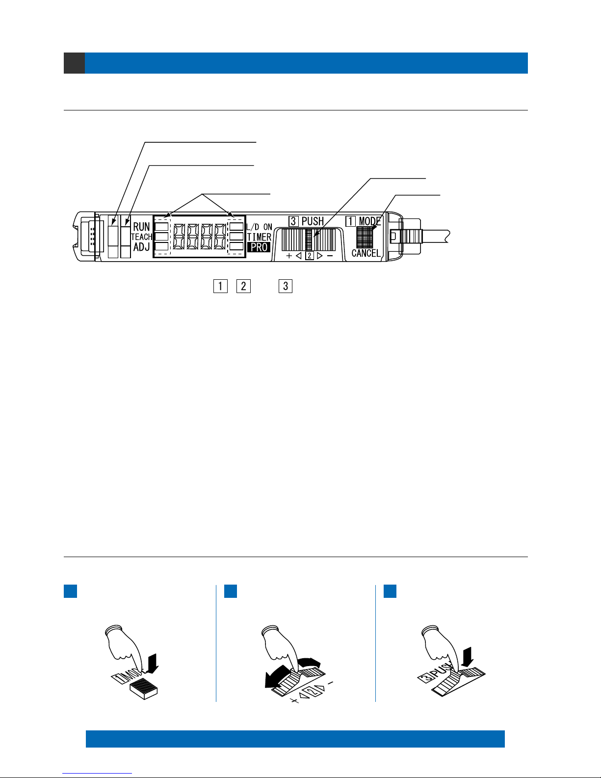
1 Operation indicator (Orange) … Lights up when output is ON.
2 Stability indicator (Green) … Lights up when the incident light intensity is great enough for stable operation.
3 MODE indicator … RUN (Green)
TEACH (Yellow)
ADJ (Yellow) :
L/D ON (Yellow) :
TIMER (Yellow) :
PRO (Yellow) :
4 Jog switch … Moving this switch in the ‘’ or ‘’ direction, allows different items to be viewed for
selection and pressing the switch then confirms the selected setting.
5 MODE key …
This key is used to select operating modes and to cancel settings during the configuration process.
The use [MODE key] and [Jog switch] are utilized to configure various settings.
Cancel: If the [MODE key] is pressed, the unit will return to the previous settings status, immediately before the [Jog switch] was pressed.
Selection and confirmation of settings are performed according to the order of the numbers, as shown on the amplifier: 1, 2 and 3.
Press the [MODE key]
(mode selection/cancellation)
1
Move the [Jog switch] in the ‘’ or ‘’ direction
(chooses setting for selection)
2
Press the [Jog switch]
(confirms the selected setting)
3
1Operation indicator (Orange)
2Stability indicator (Green)
3MODE indicator
4Jog switch
5MODE key
, and are in the correct order for selecting settings.
Lights up during normal sensing operation.
When this indicator lights up, the ‘threshold value’ for the FX-301 (Red LED
type) and FX-303 can be set by utilizing either ‘2-level teaching’ or ‘limit
teaching’. The ‘threshold value’ for the FX-301B/G/H (Blue, Green and
Infrared LED types) can be set by utilizing either ‘2-level teaching’, ‘limit
teaching’ or ‘full-auto teaching’. When the FX-302 is in window comparator
mode, the ‘threshold value’ can be set by either ‘1-level teaching’, ‘2-level
teaching’ or ‘3-level teaching’ whenever this indicator lights up.
When this indicator lights up, fine adjustment of the ‘threshold value’
can be performed.
When this indicator lights up, the output operation setting can be done.
When this indicator lights up, timer operation can be configured.
When this indicator lights up, further advanced functions, such as the
copying and memory functions, can be set.
1

Diagram of Functions and Settings
2-1. Diagram of Functions and Settings
2
The amplifier features and settings are generally classified into two main modes; the ‘NAVI mode’ for items and
settings that are frequently reconfigured, and the ‘PRO mode’ that contains more detailed settings.
Allows fine adjustment of the
‘threshold value’. (Refer to p.16~)
Adjust
ADJ
The ‘threshold value’ for the FX-301 and FX-303 can be set by
utilizing either ‘2-level teaching’ or ‘limit teaching’ , and the ‘threshold
value’ for the FX-301B/G/H can be set using these and also a third
mode called ‘full-auto teaching’. When the FX-302 is in window
comparator mode, the ‘threshold value’ can be set by either ‘1-level
teaching’, ‘2-level teaching’ or ‘3-level teaching’. (Refer to p.9~)
Teaching
TEACH
This indicates normal sensing
operation.
Run
RUN
NAVI
mode
PRO
mode
Sets output operation either LightON, or Dark-ON. (Refer to p.19)
L-ON/D-ON
L/D ON
Configures operation of the timer.
(Refer to p.20)
Timer
TIMER
Allows various detailed settings to be
configured, such as optical communications,
save/load and other settings.
Pro
PRO
Switches among response
times. (Refer to p.24)
Response Time Change
Configures timer operation and
timer period. (Refer to p.25~)
Timer Setting
Allows the selection of hysteresis level. (Refer to p.27)
Hysteresis
PRO1
PRO2
PRO3
PRO4
PRO5
Shifts the ‘threshold value’ by a certain
percentage increment during ‘limit teaching’
or ‘full-auto teaching’. (Refer to p.29)
Shift
Permits selection of stability indicator
response levels for changes in the
range for lighting up. (Refer to p.28)
Stability
Allows selection of different
content to be viewed in the
digital display. (Refer to p.33)
Digital Display Setting
Sets the viewing orientation of
the digital display.
(Refer to p.34)
Digital Display Inversion
Sets the digital display to turn
off automatically.
(Refer to p.35~)
ECO Mode Setting
Loads configuration setting
from the data bank.
(Refer to p.39)
Data Bank Load
Saves configuration setting
into the data bank.
(Refer to p.40)
Data Bank Save
Using optical communications, configuration
settings from the main unit are copied to connected
sub units, in a single step. (Refer to p.42)
Copy
Using optical communications,
configuration settings can be loaded from
data banks, in a single step. (Refer to p.43)
Remote Data Bank Load
Using optical communications,
configuration settings can be saved into
data banks, in a single step. (Refer to p.44)
Remote Data Bank Save
Allows all communication changes to be disabled during
the execution of single-step copy, load and save
operations using optical communications. (Refer to p.46.)
Transmission Change
To Permit/Not to Permit
Verifies whether optical communications
have been properly established.
(Refer to p.45)
Test
Allows basic configuration information
to be set in a single step, by inputting
a 4-digit code. (Refer t o p .4 9 )
Coding
Forces the numerical value for
incident light intensity to ‘0’, on
the digital display. (Refer to p.50)
Zero Adjust
Allows fine adjustment of the ‘threshold
value’ to be directly performed during
RUN mode. (Refer to p.51)
Adjust Lock
All settings, except for data
bank information, revert to
factory settings. (Refer to p.52)
Reset
P.21~
P.31~
P.38~
PRO6
Configures window comparator
mode and teaching method.
(Refer to p.54)
Window Comparator Mode Setting
Configures the hysteresis
(IN/OUT) when in window
comparator mode. (Refer to p.55)
Window Comparator Hysteresis
P.53~
P.41~
P.47~
FX-301
FX-303
* Available only in FX-301B/G/H, FX-302
* Available only in FX-302
* The FX-303 is not
equipped with a PRO4
setting function.
2
Others
3-1. Precautions When Selecting Settings
3
Press the MODE
key once.
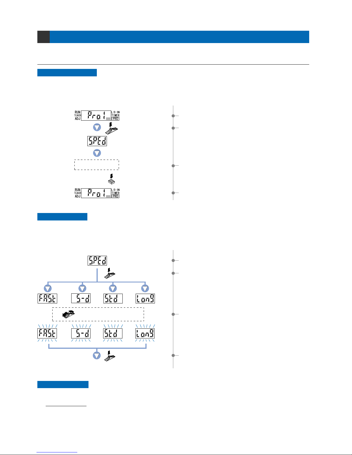
Example: When operating in PRO mode.
Press the Jog
switch once.
To cancel
Canceling operations
1Select ‘PRO mode’.
To cancel any operation, press the [MODE key]. If the [MODE key] is pressed once, the unit will return to
the previous settings status, immediately before the [Jog switch] was pressed.
When changing the status of any setting, ensure that the selected setting is subsequently confirmed.
If confirmation is not performed, the new setting will not take effect.
Confirming settings
Example: When setting response time change.
S-D
(
reduced
intensity
)
STD
(standard)
FAST
(high-speed)
LONG
(long-range)
Press the Jog switch.
Press the Jog switch.
Select the desired mode
by moving the Jog switch.
The digital display will quickly blink 3 times to
confirm the setting.
2If the [Jog switch] is pressed, the current mode
will be displayed.
* The factory setting is STD (standard).
4If the [Jog switch] is pressed, the digital display
will quickly blink 3 times, contriming the setting.
Operation protection
1Select ‘response time change’.
2If the [Jog switch] is pressed once, the unit enter
the ‘response time change’ state.
3If the [Jog switch ] is moved, the digital display
will blink.
Select the desired mode.
3To cancel the ‘response time change’ operation,
press the [MODE key] once.
4The display will return to the previous [PRO1 mode]
selection screen.
You can use the ‘key lock function’ to protect these operations. (Refer to p.56.)
Key lock function (FX-301B/G/H only)
This function can be used to prevent the operator from accidentally changing the sensor settings.
3
3-3. Error Display Indicator Readings
In case of errors, attempt the following measures:
Notes: 1)This digital display is 10 ms OFF-delay timer.
2)Full-auto teaching can be set only in the FX-301B/G/H.
3)When in window comparator mode, the factory settings for teaching method and shift value are, respectively: ‘1-level teaching’ and ‘100’.
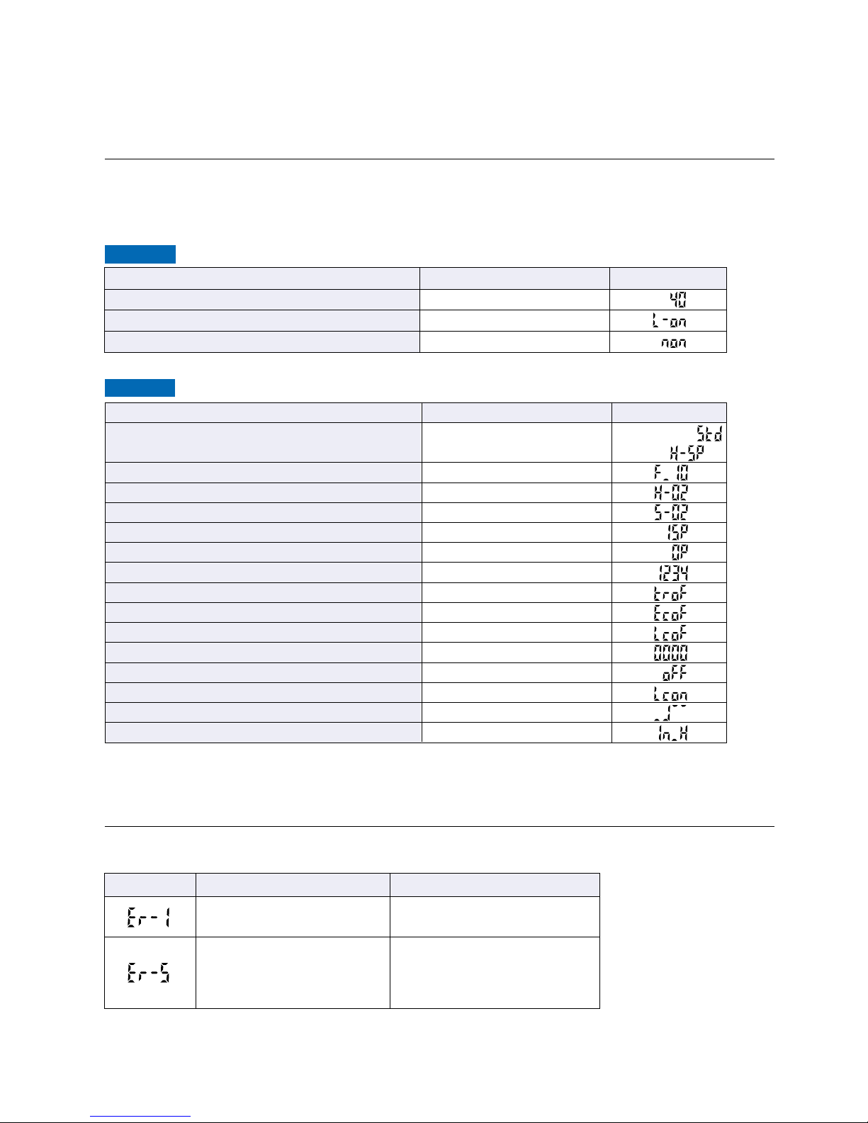
3-2. Factory Settings
NAVI mode
PRO mode
Item
Response time
Timer period
Hysteresis
Stability
Amount of shift during limit teaching
Amount of shift during full-auto teaching
(Note 2)
Display
Display orientation
ECO mode
Selection for transmission change to permit/not to permit (FX-301B/G/H and FX-302 only)
Code
0_ADJ
Adjust Lock
Window comparator mode (FX-302 only)
(Note 3)
Window comparator hysteresis (FX-302 only)
Settings
Standard
10 ms
H-02 (standard)
S-02 (standard)
15 %
0 %
Incident light intensity display
OFF
OFF
OFF
0000
OFF
OFF
OFF
IN Hysteresis
Digital display
(Note1)
Item
Threshold value
Light state operation
Timer operation
Settings
40
L-ON (ON when light is received)
Without timer
Digital display
Digital display
Error description Measures
Turn off the power, then check
the load.
The load has short-circuited
and excess current is flowing.
Confirm that all amplifier units are
properly connected to each other.
Communication error has
occurred at time of connection.
In case of using functions
of PRO4 mode
Factory settings for the FX-301/302/303 are indicated below:
If the unit is reset using the ‘9-5 Setting Reset Function’ from ‘PRO5 Mode’ on p.52, the resulting settings will be
those indicated below:
()
FX-301, FX-302:
FX-303:
4
Settings for NAVI Mode
4-1. NAVI Mode Functions and Settings
4
In [NAVI mode], frequently changed settings can be easily configured.
Settings for four functions can be configured.
RUN :
Normal Sensing Operation
TEACH : Teaching Mode
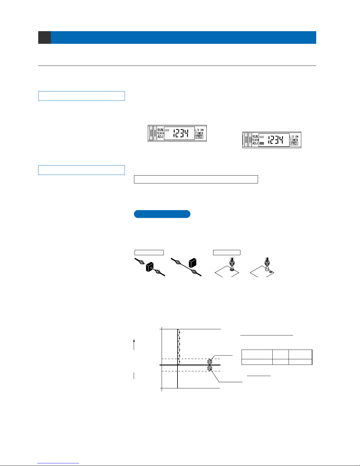
This indicates normal sensing operation. Incident light intensity is displayed in real
time. When set to factory settings, the ‘threshold value’ cannot be manually changed.
When the ‘Adjust Lock Setting Function’ in ‘PRO5 Mode’ is disabled, manual fine
adjustment of the ‘threshold value’ can be performed during normal sensing operation.
This mode sets the ‘threshold value’ by utilizing teaching.
When using FX-301,FX-303 or FX-302 normal mode
The ‘threshold value’ can be set by utilizing either ‘2-level teaching’ or ‘limit
teaching’, and the ‘threshold value’ for the FX-301B/G/H can be set using these
and also ‘full-auto teaching’.
2-level teaching is a method of setting the threshold value by teaching the
amplifier unit two different status conditions - sensing object present and sensing
object not present.
The ‘threshold value’ is usually set using this method.
Normal sensing operation * Normal sensing operation when
‘threshold value’ can be fine adjusted
Refer to the section entitled ‘9-4 Adjust Lock
Setting Function’ from ‘PRO5 Mode’ on p.51.
Refer to p.9 ~ for setting procedure
P.9
2-level Teaching
Incident
light margin
Light interruption
margin
Incident light intensity
Threshold value
Number of times that the stability indicator blinks
Number of blinks - 0
Number of blinks - 1
Number of blinks - 2
Number of blinks - 3
Number of blinks - 4
Number of blinks - 5
Incident light
intensity during
teaching (high)
Incident light
intensity during
teaching (low)
(Example)
Threshold
value
2,000/4,000 3,000
Incident light intensity during
2-level teaching (high)
Threshold value
Number of
blinks
–
Incident light margin
4,000 – 3,000
300
Incident light
margin
10 %
3 times
=
=
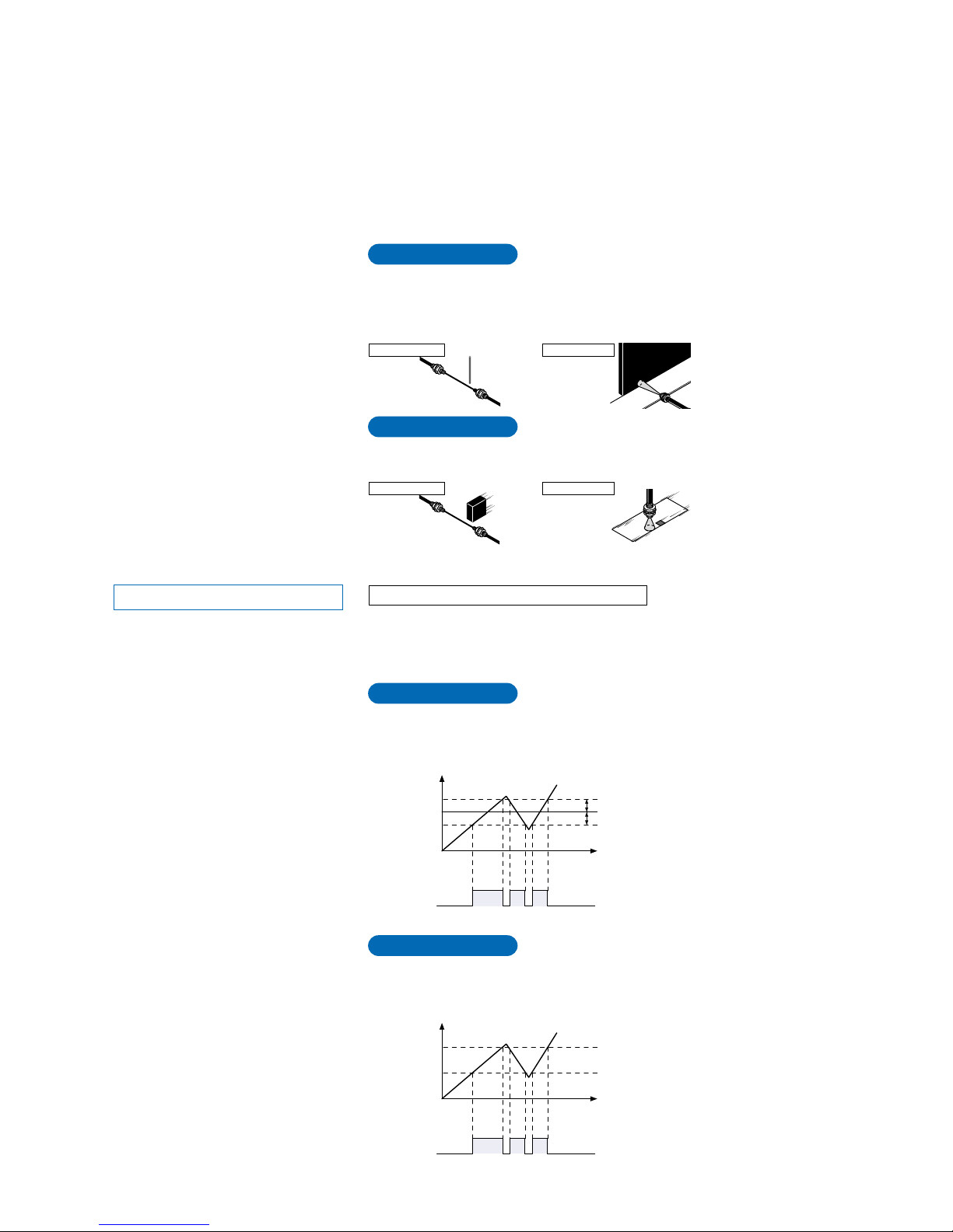
Thru-beam type Reflective type
Workpiece present Workpiece absent Workpiece present Workpiece absent
When 2-level teaching is being performed, the stability indicator will blink a certain
number of times. The number of blinks indicates the number of times by which the
difference between the incident light intensity during teaching and the ‘threshold
value’ for incident light intensity, exceeds the incident light margin.
Incident light intensity
during 2-level teaching
5
TEACH : Teaching Mode
Refer to p.12 ~ for setting procedure
P.12
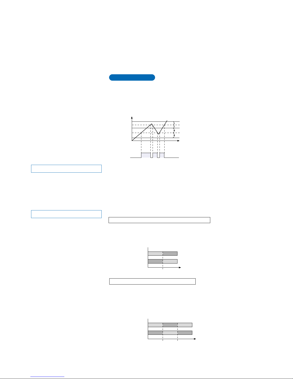
1-level Teaching
When using FX-302 window comparator mode
The ‘threshold value’ can be set with any of the 3 teaching methods, ‘1-level
teaching’, ‘2-level teaching’ and ‘3-level teaching’. By setting two ‘threshold
values’, both ON and OFF can occur between the two threshold value levels.
This is the method of setting the threshold values (1_SL, 2_SL) by one level
(P-1) teaching. The shift value can be set as desired.
P.13
2-level Teaching
This is a method of setting the threshold values (1_SL, 2_SL) by two levels
(P-1, P-2) teaching.
Time
ON
P-1
1_SL
P-2
2_SL
0
OFF
Time
Shift value
Shift value
ON
1_SL
2_SL
P-1
0
OFF
Incident light
intensity
4,000
Incident light
intensity
4,000
Output
(L-ON)
Output
(L-ON)
* In this figure, the incident light intensity of
P-1 is less than that of P-2.
Teaches only the status condition in which no sensing object is within sensing
range (status in which incident light intensity is stable). This method is used to set
a ‘threshold value’ for conducting sensing in the presence of a background, or
when extremely small objects are to be detected.
P.10
Limit Teaching
Very small object
P.11[FX-301B/G/H(Blue, Green and Infrared LED types) only]
Full-auto Teaching
This method is used to set the threshold value while the workpieces are still
moving on the production line, without stopping the production line.
Thru-beam type
Thru-beam type
Reflective type
Reflective type
Background
6
ADJ : Threshold Value Fine Adjustment Mode
This mode allows fine adjustment of the ‘threshold value’ setting.
When the incident light intensity display has been selected, the threshold value
can be adjusted in increments as low as a one digit.
When the percentage display has been selected, the threshold value can be
adjusted in increments of one digit (varies depending on the ‘threshold value’).
However, when FX-302 is in window comparator mode, the percentage display
function cannot be utilized.
* The factory setting is 40.
Refer to p.16~ for setting procedure
ONOFF OFF
OFFON ON
0
Threshold value
Threshold
value 1
Threshold
value 2
Incident light
intensity
Incident light
intensity
4,000
ONOFF
OFFON
Output
operation
L-ON
D-ON
Output
operation
L-ON
D-ON
* The factory setting is L-ON (Light-ON).
0 4,000
L/D ON : Output Operation Setting Mode
Refer to p.19 for setting procedure
When using FX-301, FX-303 or FX-302 normal mode
When using FX-302 window comparator mode
When set to ‘Light-ON’, the output will be ON if the incident light intensity becomes
greater than the ‘threshold value’.
When set to ‘Dark-ON’, the output will be ON if the incident light intensity becomes
less than the ‘threshold value’.
When set to ‘Light-ON’, if the incident light intensity is between the two ‘threshold
value’ levels, the output will be ON. If the incident light intensity is outside of the
two threshold value levels, the output will be OFF.
When set to ‘Dark-ON’, if the incident light intensity is between the two ‘threshold
value’ levels, the output will be OFF. If the incident light intensity is outside of the
two threshold value levels, the output will be ON.
This mode allows the selection of output operation from either Light-ON, or Dark-ON.
ON
A
1_SL
2_SL
B
C
0
OFF
P.14~
3-level Teaching
This is a method of setting the threshold range by three levels (P-1, P-2, P-3)
teaching and set the threshold values at the middle of ‘A’ and ‘B’ (1_SL) and
‘B’and ‘C’ (2_SL).
After teaching, P-1, P-2 and P-3 are automatically assigned in ascending order to
‘A’, ‘B’, and ‘C’.
Time
Incident light
intensity
4,000
Output
(L-ON)
7

PRO mode allows the configuration and usage of the following additional
timer operations: OFF-delay, ON-delay and ONE-SHOT.
Timer period can be selected from 0.5 ms to 500 ms.
Please refer to the section entitled ‘5-3 Timer Setting Function (FX-301
and FX-303)’ from ‘PRO1 Mode’ on p.25
PRO mode allows the configuration and usage of the following additional
timer operations: OFF-delay, ON-delay, ONE-SHOT, ON-delay / OFF-delay,
ON-delay / ONE-SHOT.
Timer period can be selected from 0.5 ms to 5 sec.
Please refer to the section entitled ‘5-4 Timer Setting Function (FX-302)’
from ‘PRO1 Mode’ on p.26.
TIMER : Timer Operation Setting Mode
Refer to p.20 for setting procedure
FX-302
This mode sets the operation of the timer.
Using factory settings, either ‘Without timer’ or ‘10 ms OFF-delay’ can be selected.
FX-301 and FX-303
8
Place a fiber within sensing range.
Press the
MODE key once.
Press the
Jog switch.
Status condition - sensing object is absent
Press the
Jog switch.
Difference between incident light
intensities is not great enough.
Stable sensing
Status condition - sensing object is present
Press the MODE key
5 times or keep it pressed
for 2 sec. or more.
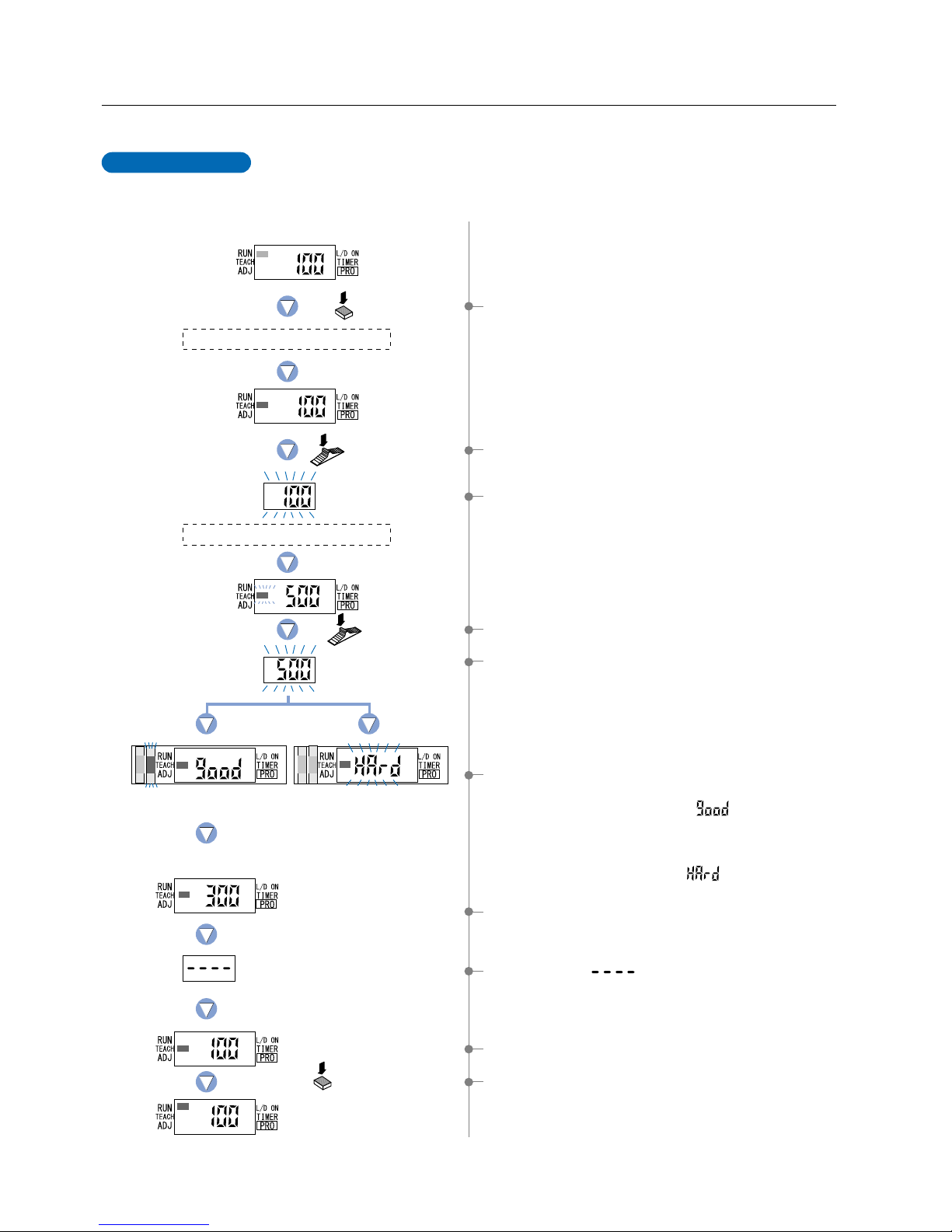
4-2. Teaching Mode (when using FX-301, FX-303 or FX-302 normal mode)
The ‘threshold value’ can be set by utilizing two kinds of teaching, either ‘2-level teaching’ or ‘limit teaching’.
2-level teaching is a method of setting the ‘threshold value’ by teaching the amplifier unit two
different status conditions - sensing object present and sensing object absent. The ‘threshold
value’ is usually set using this method.
2-level Teaching
1 Select ‘TEACH mode’ by pressing the [MODE key] once.
2 Press the [Jog switch] when in the status condition of -
sensing object is present.
4 Press the [Jog switch] when in the status condition of -
sensing object is absent.
7 The ‘threshold value’ setting will be displayed.
8 The characters ‘ ’ will be displayed.
9 The incident light intensity will again be displayed, indicating
that configuration is now complete.
0 By pressing the [MODE key] 5 times or by keeping it
pressed for 2 sec. or more, the amplifier will return
to the ‘RUN mode’ (normal sensing operation).
3The digital display will blink and indicate the incident light
intensity reading, then the MODE indicator / TEACH
(yellow) will blink.
This indicates that the second point item is now ready for
input.
5
The digital display will again blink and indicate the incident light intensity reading and
the ‘threshold value’ will be set to a value midway between the incident light
intensities when the sensing object is present and when it is absent. The blinking
MODE indicator / TEACH will stop blinking and continuously light up.
* Fine adjustment of the ‘threshold value’ can be performed in the ‘4-4 Threshold
Value Fine Adjustment Mode’ (when using FX-301, FX-303 or FX-302 normal
mode) described on p.16.
()
6 The sensing stability status will be displayed.
• When stable sensing can be performed
n
The digital display will indicate the word ‘ ’. The ‘Stability indicator’
(green) will blink. The greater the number of times it blinks, the more stable
the sensing that can be performed. (Refer to p.5 for more details.)
• When stable sensing cannot be performed
n
The digital display will blink the word ‘ ’. The ‘Stability indicator’
(green) will not light up.
9
Place a fiber within sensing range.
Press the
MODE key once.
Press the
Jog switch.
Status condition - sensing object is absent
Press the MODE key
5 times or keep it pressed
for 2 sec. or more.
Move the Jog switch
in the ‘’ or ‘’ direction.
The digital display will
scroll (twice).
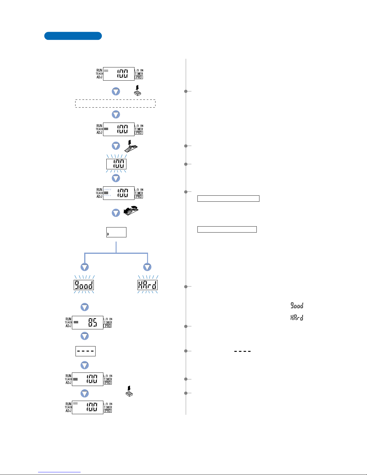
Shifting can be performed. Shifting cannot be performed.
Teaches only the status condition in which no sensing object is within sensing range (status in
which incident light intensity is stable). This method is used to set a threshold value for
conducting sensing in the presence of a background, or when extremely small objects are to be
detected.
Limit Teaching
1 Select ‘TEACH mode’ by pressing the [MODE key] once.
2 Press the [Jog switch] when in the status condition of -
sensing object is absent.
4 Move the [Jog switch] in either the ‘’ or ‘’ direction.
When using thru-beam fiber
When using reflective fiber
5 The judgement on whether the shift amount can be shifted
or not will be displayed.
•
When the shifting can be performed
nThe digital display will blink the word ‘ ’.
•
When the shifting cannot be performed
nThe digital display will blink the word ‘ ’.
6 The ‘threshold value’ setting will be displayed.
7 The characters ‘ ’ will be displayed.
8 The incident light intensity will again be displayed, indicating
that configuration is now complete.
•
If the switch is moved toward the ‘’ direction, the digital display
will scroll from the left to the right (twice) and the threshold value
will be shifted down by approximately 15 %, to a value lower than
the incident light intensity displayed (high sensitivity).
•
If the switch is moved toward the ‘’ direction, the digital display
will scroll from the right to the left (twice) and the threshold value
will be shifted up by approximately 15 %, to a value higher than
the incident light intensity displayed (low sensitivity).
*
The initial factory-set value of the shift amount is approximately 15 %.
The shift amount can be changed by utilizing the ‘5-7 Shift
Function’ from ‘PRO1 Mode’, described on p.29. (The percentage
adjustment is variable from 5 % to 80 %, in increments of 5 %.)
9By pressing the [MODE key] 5 times or by keeping it
pressed for 2 sec. or more, the amplifier will return to the
‘RUN mode’ (normal sensing operation).
3The digital display will blink and indicate the incident light
intensity reading, then the MODE indicator / TEACH
(yellow) will blink.
10
Place a fiber within sensing range.
Pless the MODE
key once.
Keep the Jog switch
pressed for 0.5 sec.
or more.
Status condition-moving the production line.
Press the MODE key
5 times or keep it pressed
for 2 sec. or more.
Stable sensing Difference between
incident light intensities
is not great enough.
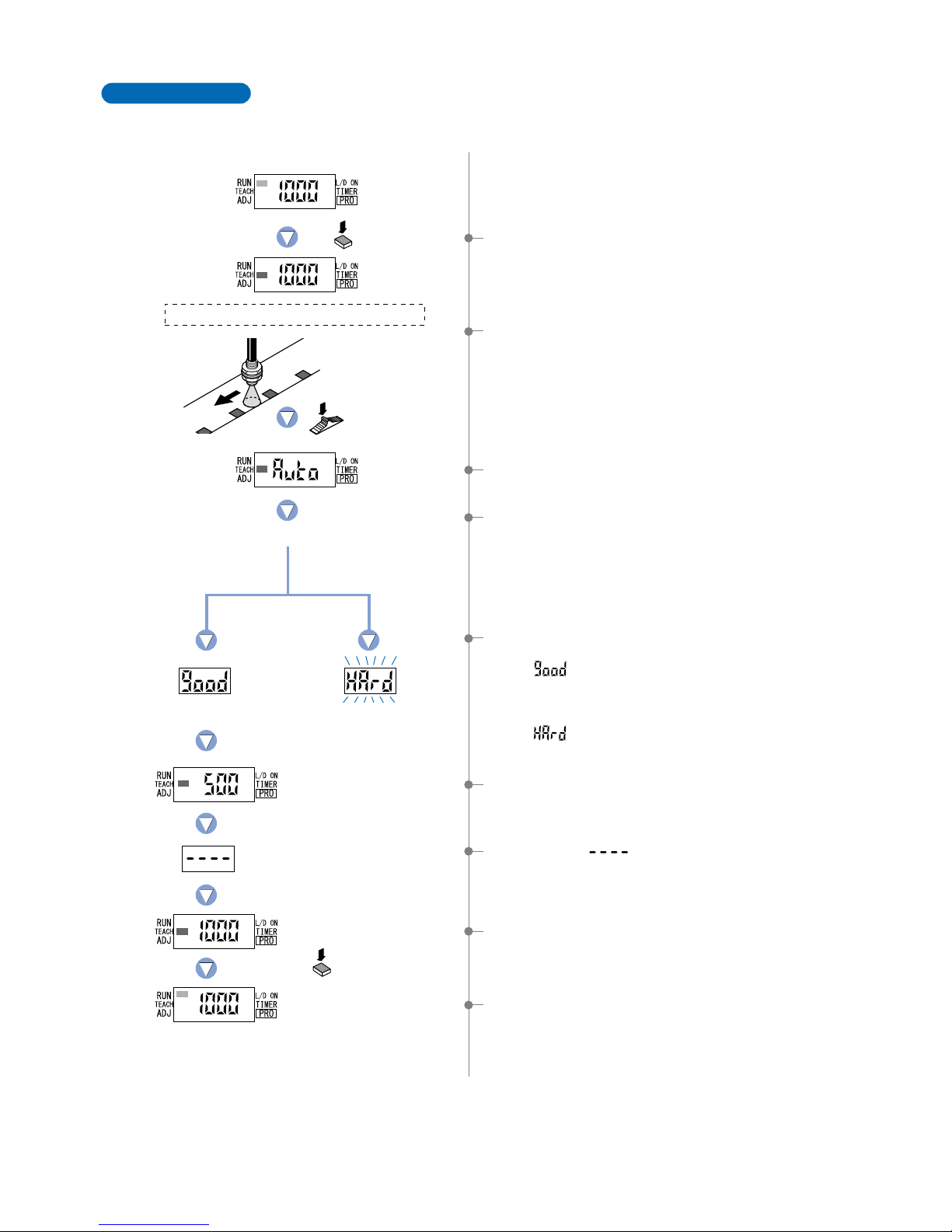
Full-auto teaching is used to set the threshould value while the workpieces are still moving on the
production line, without stopping the production line.
[This setting method is used only in the FX-301B/G/H (Blue, Green and Infrared LED types)]
Full-Auto Teaching
1Select ‘TEACH mode’ by pressing the [MODE key] once.
5The judgement on the stability of sensing will be displayed.
•
In case stable sensing is possible.
n‘ ’ will be displayed. Stability indicator (green) will blink.
More blinking number indicates more stable sensing.
( Refer to p.5 for detail.)
•
In case stable sensing is not possible.
n‘ ’ will blink. Stability indicator (green) will be off.
6The ‘threshold value’ setting will be displayed.
7The characters‘ ’ will be displayed.
4The threshold value is set to the middle value of the incident light
intensity levels in the object present and object absent conditions.
* The threshold value can be shift by utilizing ‘5-7 Shift Function’
from ’PRO1 MODE’ on p.29.
(
The percentage adjustment is variable from 45 % to 45 %, in
)
increments of 5 %. The initial setting is 0 %.
9By pressing the [MODE key] 5 times or by keeping it pressed
for 2 sec. or more, the amplifer will return to the ‘RUN mode’
(nomal sensing operation).
8The incident light intensity will again be displayed, indicating
that configuration is now complete.
3‘AUTO’ is displayed on the display.
Release the jog switch when the object has passed.
2Keep the [Jog switch] pressed for 0.5 sec. or more when in the
status condition when the object moving on the production line.
11
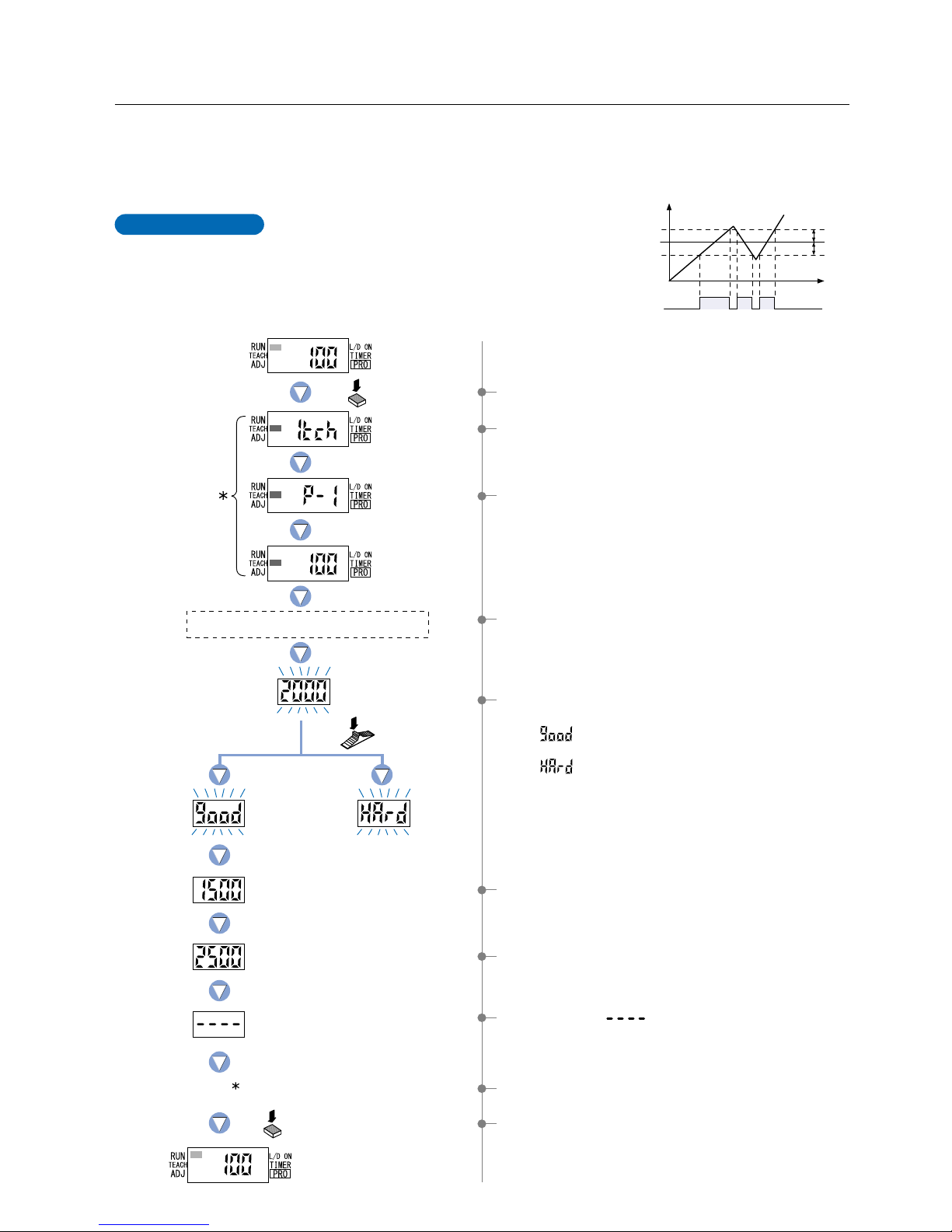
This is the method of setting the threshold values
(1_SL, 2_SL) by one level (P-1) teaching. The shift
value can be set as desired
* The factory setting for shift value is ‘100’. To set the shift value,
refer to the section entitled ‘10-2. Window Comparator Mode
Setting Function’ from ‘PRO6 Mode’ on p. 54.
1Select ‘TEACH mode’ by pressing the [MODE key] once.
2The current teaching method will be displayed.
8The characters ‘ ’ will be displayed.
4-3. Teaching Mode (when using FX-302 window comparator mode)
1-level Teaching
Time
Shift value
Shift value
ON
1_SL
2_SL
P-1
0
OFF
Incident light
intensity
4,000
Output
(L-ON)
Press the
MODE key once.
Press the
Jog switch.
If the shift value has
been set to 500.
Lower limit value 1_SL
Upper limit value 2_SL
Upper and lower limits have
not been properly set.
Incident light
intensity for P-1.
The status condition when a sensing object is
present that can be used as a standard.
Press the MODE key 5
times or keep it pressed for
2 sec. or more.
0By pressing the [MODE key] 5 times or by keeping it
pressed for 2 sec. or more, the amplifier will return to the
‘RUN mode’ (normal sensing operation).
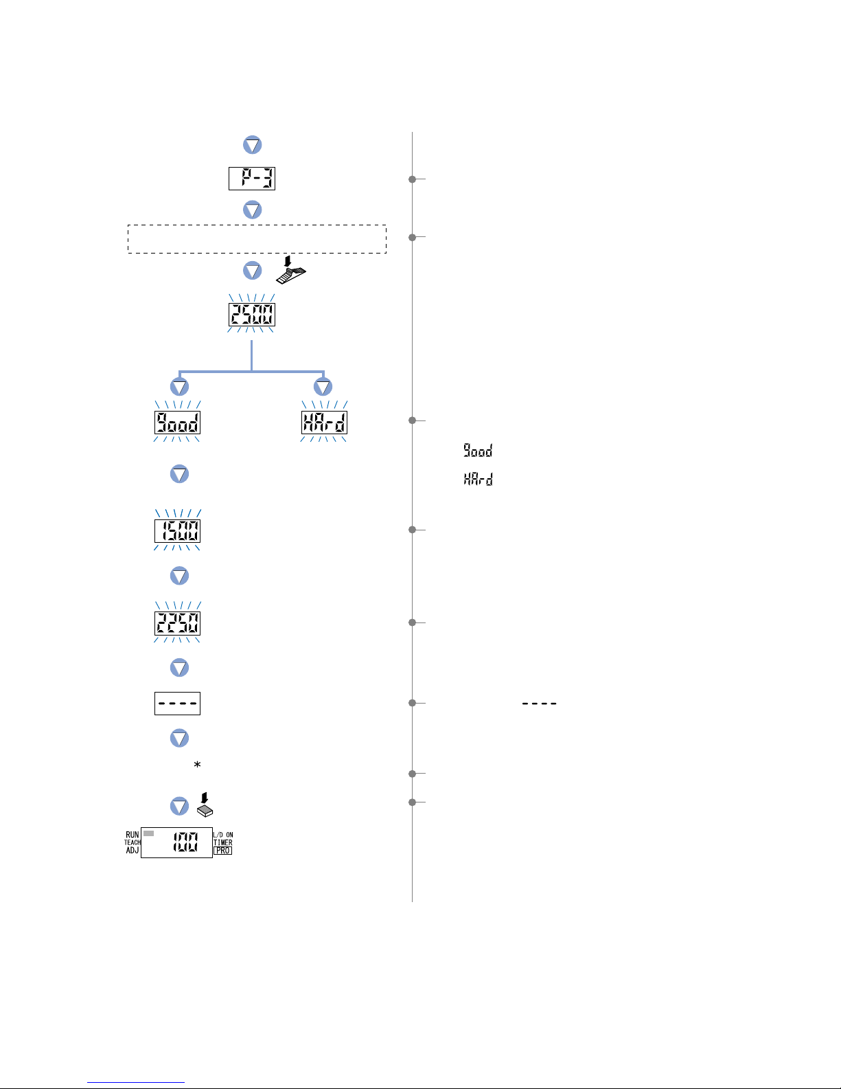
The ‘threshold value’ can be set using ‘1-level teaching’, ‘2-level teaching’ or ‘3-level teaching’. When FX-302 is in window comparator
mode, teaching is performed using the teaching methods described in the section entitled ‘10-2. Window Comparator Mode Setting
Function’ from ‘PRO6 Mode’ on p. 54. To change the teaching method, follow the procedures also described under the same heading.
* The factory setting is ‘1-level teaching’.
3The unit has entered the ‘P-1’ setting state.
6The setting for ‘lower limit value 1_SL’ will be displayed.
7The setting for ‘upper limit value 2_SL’ will be displayed.
5The display will indicate whether the upper and lower
threshold value limits have been correctly set.
• If ‘ ’ is blinking…the upper and lower limits have
been set correctly.
• If ‘ ’ is blinking…the upper and lower limits have not
been set correctly.
* The factory setting for shift value is ‘100’.
To set the shift value, refer to the section entitled ‘10-2. Windo w
Comparator Mode Setting Function’ from ‘PRO6 Mode’ on p. 54.
4If the [Jog switch] is pressed while in the status condition
when a sensing object is present that can be used as a
standard, then the display will blink and indicate the incident
light intensity.
9The incident light intensity will again be displayed, indicating
that configuration is now complete.
The symbol ‘ ’ will be
displayed repeatedly.
12
Incident light
intensity for P-2.
The status condition when a sensing object is present
that can be used as a standard for the lower limit.
The status condition when a sensing object is present
that can be used as a standard for the upper limit.
Upper and lower limits have
not been properly set.
8The setting for ‘lower limit value 1_SL’ will be displayed.
9The setting for ‘upper limit value 2_SL’ will be displayed.
0The characters ‘ ’ will be displayed.
AThe incident light intensity will again be displayed, indicating
that configuration is now complete.
BBy pressing the [MODE key] 5 times or by keeping it
pressed for 2 sec. or more, the amplifier will return to the
‘RUN mode’ (normal sensing operation).
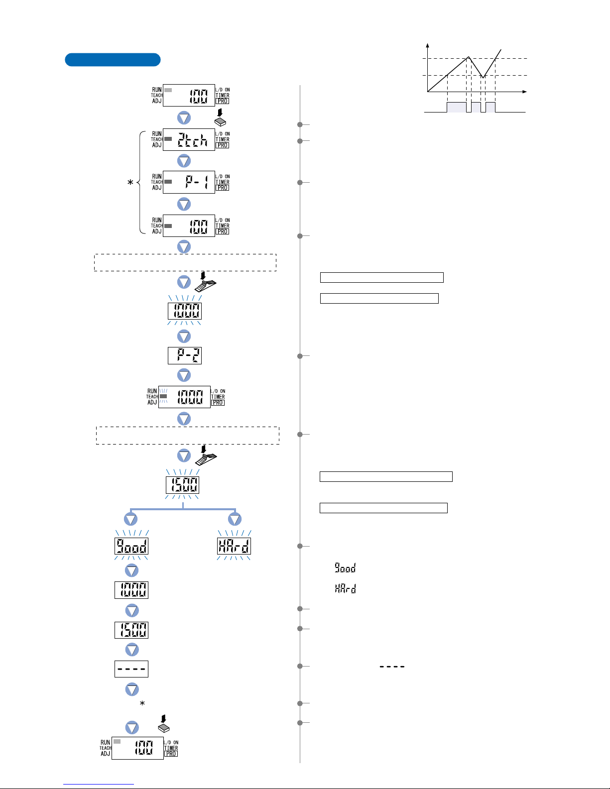
2-level Teaching
This is a method of setting the threshold values
(1_SL, 2_SL) by two levels (P-1, P-2) teaching.
Time
ON
P-1
1_SL
P-2
2_SL
0
OFF
Incident light intensity
4,000
Output
(L-ON)
1Select ‘TEACH mode’ by pressing the [MODE key] once.
2The current teaching method will be displayed.
3The unit has entered the ‘P-1’ setting state.
Press the
Jog switch.
Press the
Jog switch.
Press the
MODE key once.
Incident light
intensity for P-1.
Lower limit value 1_SL
Upper limit value 2_SL
Press the MODE key 5
times or keep it pressed for
2 sec. or more.
4If the [Jog switch] is pressed while in the status condition
when a sensing object is present that can be used as a
standard for the lower limit, then the display will blink and
indicate the intensity of incident light.
When using thru-beam type fibers
•
Press the [Jog switch] for the sensing object that has the greatest amount of blocked light.
When using reflective type fibers
• Press the [Jog switch] for the sensing object with the lowest intensity of incident light.
Note) Even if procedures 4 and 6 are reversed, teaching for a
sensing object with low intensity incident light will
automatically cause the setting of ‘lower limit value 1_SL’.
6If the [Jog switch] is pressed while in the status condition
when a sensing object is present that can be used as a
standard for the upper limit, then the display will blink and
indicate the incident light intensity.
When utilizing thru-beam type fibers
• Press the [Jog switch] for the sensing object that has the
least amount of blocked light.
When utilizing reflective type fibers
• Press the [Jog switch] for the sensing object with the
greatest incident light intensity .
5The unit has entered the ‘P-2’ setting state and ‘TEACH’
(yellow) will begin to blink on the MODE display.
7The display will indicate whether the upper and lower limits
have been correctly set.
• If ‘ ’ is blinking… the upper and lower limits have
been set correctly.
• If ‘ ’ is blinking… the upper and lower limits have not
been set correctly.
The symbol ‘ ’ will be
displayed repeatedly.
13
ON
A
1_SL
2_SL
B
C
0
OFF
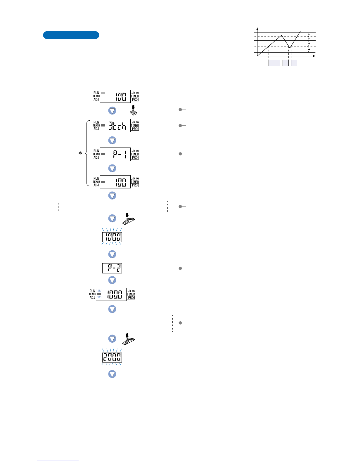
3-level Teaching
This is a method of setting the threshold range by
three levels (P-1, P-2, P-3) teaching and set the
threshold values at the middle of ‘A’ and ‘B’ (1_SL) and
‘B’and ‘C’ (2_SL).
After teaching, P-1, P-2 and P-3 are automatically
assigned in ascending order to ‘A’, ‘B’, and ‘C’.
Time
Incident light
intensity 4,000
Output
(L-ON)
Press the
MODE key once.
Press the
Jog switch.
Press the
Jog switch.
The status condition when sensing object ‘A’ is present
that has the lowest intensity of incident light.
Incident light
intensity for P-1.
Incident light
intensity for P-2.
1Select ‘TEACH mode’ by pressing the [MODE key] once.
2The current teaching method will be displayed.
3The unit has entered the ‘P-1’ setting state.
4If the [Jog switch] is pressed while in the status condition
when sensing object ‘A’ is present that has the lowest
intensity of incident light, then the display will blink and
indicate the incident light intensity.
5The unit has entered the ‘P-2’ setting state and ‘TEACH’
(yellow) will begin to blink on the MODE display.
6If the [Jog switch] is pressed while in the status condition
when sensing object ‘B’ is present that has an incident light
intensity in between that of sensing object ‘A’ and sensing
object ‘C’, the display will blink and indicate the incident light
intensity.
The status condition when sensing object ‘B’ is present that
has an incident light intensity in between that of sensing
object ‘A’ and sensing object ‘C’.
14
Press the
Jog switch.
Upper and lower limits have
not been properly set.
Lower limit value 1_SL
Upper limit value 2_SL
The status condition when sensing object ‘C’ is present
that has the greatest intensity of incident light.
Press the MODE key 5 times
or keep it pressed for 2 sec. or
more.
7The unit has entered the ‘P-3’ setting state.
BThe characters ‘ ’ will be displayed.
CThe incident light intensity will again be displayed, indicating
that configuration is now complete.
DBy pressing the [MODE key] 5 times or by keeping it
pressed for 2 sec. or more, the amplifier will return to the
‘RUN mode’ (normal sensing operation).
Incident light
intensity for P-3.
8If the [Jog switch] is pressed while in the status condition
when sensing object ‘C’ is present that has the greatest
intensity of incident light, the display will blink and indicate
the incident light intensity.
0The setting for ‘lower limit value 1_SL’ will be displayed.
AThe setting for ‘upper limit value 2_SL’ will be displayed.
9The display will indicate whether the upper and lower limits
have been correctly set.
• If ‘ ’ is blinking… the upper and lower limits have
been set correctly.
• If ‘ ’ is blinking… the upper and lower limits have not
been set correctly.
The symbol ‘ ’ will be
displayed repeatedly.
15
Press the
MODE key twice.
Press the
Jog switch.
Press the MODE key
4 times or keep it pressed
for 2 sec. or more.
The current
threshold
value setting
Move the
Jog switch.
Select the desired threshold value
by moving the Jog switch.
When changing
threshold value
to 35.
The digital display will quickly
blink 3 times to verify the value.
If the switch is
moved toward
the ‘’ direction.
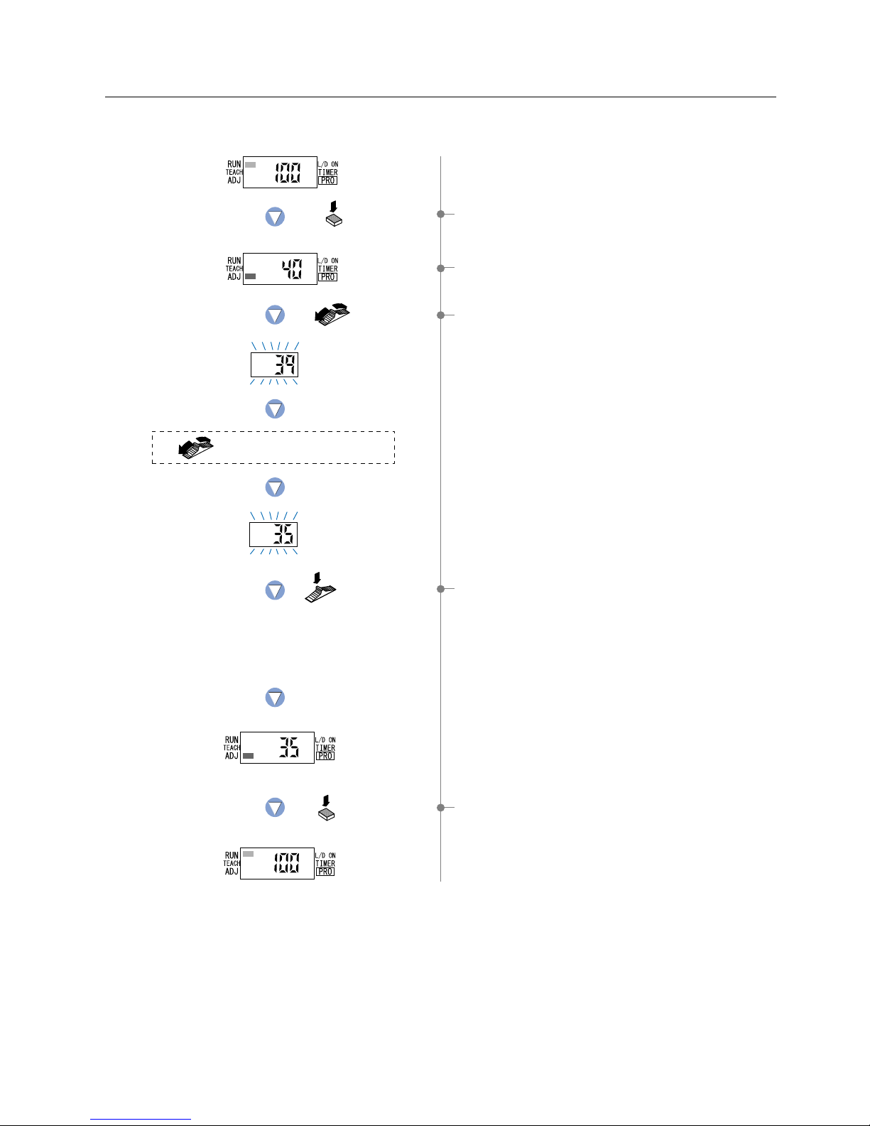
4-4.
Threshold Value Fine Adjustment Mode (when using FX-301, FX-303 or FX-302 normal mode)
This mode allows fine adjustment of the ‘threshold value’ setting.
1 Press the [MODE key] twice to select the ‘threshold value
fine adjustment mode’.
2 The current ‘threshold value’ will be displayed.
* The factory setting is 40.
3 If the [Jog switch] is moved toward the ‘’ or ‘’ direction,
the ‘threshold value’ will change and the new value will blink.
If an increased ‘threshold value’ is desired,
move the [Jog switch] toward the ‘
’ direction.
If a decreased ‘threshold value’ is desired,
move the [Jog switch] toward the ‘
’ direction.
4 If the [Jog switch] is pressed, the digital display will quickly
blink 3 times, confirming the setting of the currently displayed
‘threshold value’.
5 Press the [MODE key] 4 times or keep it pressed for
2 sec. or more to return to ‘RUN mode’ (normal sensing
operation).
16
Press the
MODE key twice.
Select the desired threshold value
by moving the Jog switch.
The digital display will quickly
blink 3 times to verify the value.
Press the
Jog switch.
Press the
Jog switch.
Move the
Jog switch.
When changing
threshold value
to 85.
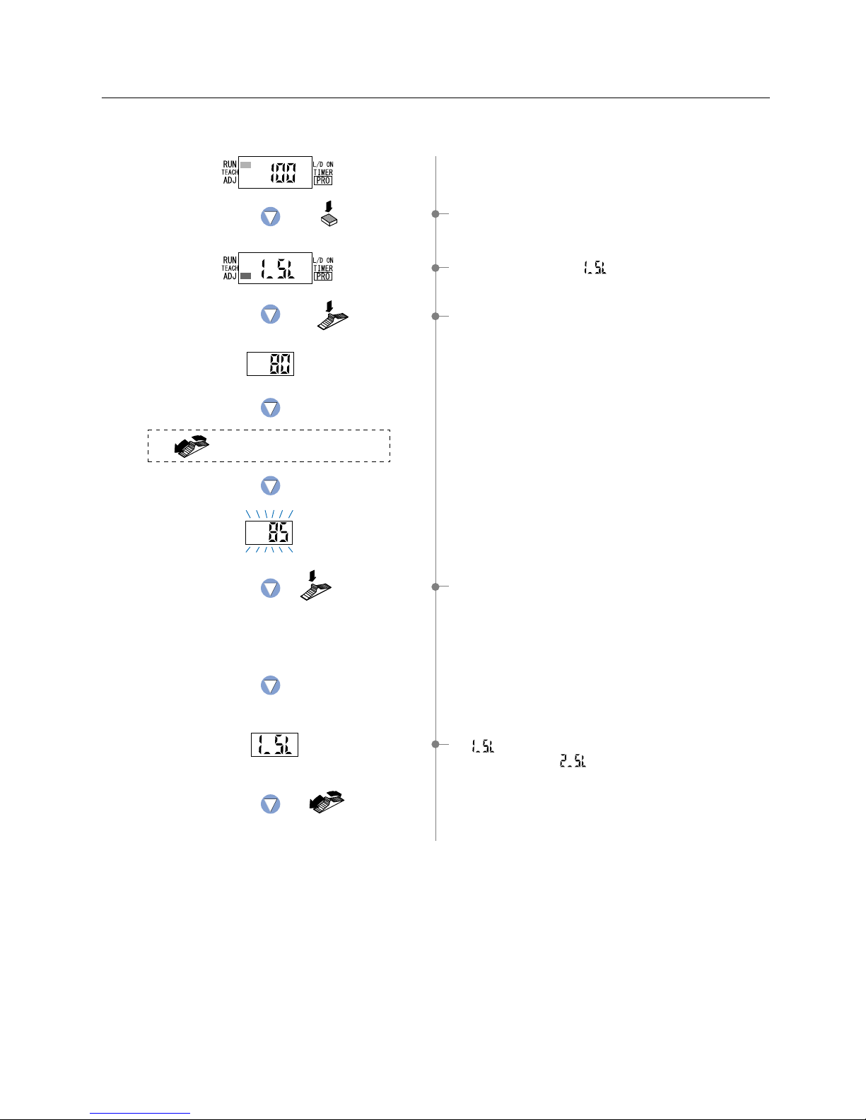
2The lower limit setting ‘ ’ is displayed.
4-5.
Threshold Value Fine Adjustment Mode (when using FX-302 window comparator mode)
This mode allows fine adjustment of the ‘Threshold value(1_SL, 2_SL)’ setting.
1 Press the [MODE key] twice to select the ‘threshold value
fine adjustment mode’.
3 If the [Jog switch] is pressed, the threshold value for
‘1_SL’ is displayed.
If an increased ‘threshold value’ is desired,
move the [Jog switch] toward the ‘
Ⳮ’ direction.
If a decreased ‘threshold value’ is desired,
move the [Jog switch] toward the ‘
ⳮ’ direction.
4 If the [Jog switch] is pressed, the display will blink quickly
three times and the threshold value for ‘1_SL’ will be set.
5 ‘ ’ is displayed. If the [Jog switch] is moved, then the
upper limit setting ‘ ’ is displayed.
17
 Loading...