

Page 1
1. Functional Description
1-1. Functional Description ..........................P.1
1-2. Setting Procedure.................................P.1
2. Diagram of Functions and Settings
2-1. Diagram of Functions and Settings......P.2
3. Others
3-1.
Precautions When Selecting Settings
.....P.3
3-2. Factory Settings ...................................P.4
3-3. Error Display Indicator Readings .........P.4
3-4.
Introducing FX-301(P) Updated Version Unit
..P.5
4. Settings for NAVI Mode
4-1. NAVI Mode Functions and Settings .....P.6
4-2. Teaching Mode
[when using FX-301(P)(-HS) or FX-305(P) normal mode]
P.10
4-3. Teaching Mode
[when using FX-305(P) window comparator mode]
P.13
4-4. Threshold Value Fine Adjustment Mode
[when using FX-301(P)(-HS) or FX-305(P) normal mode]
P.19
4-5. Threshold Value Fine Adjustment Mode
[when using FX-305(P) window comparator mode]
P.20
4-6. Output Operation Setting Mode .........P.22
4-7. Timer Operation Setting Mode...........P.23
5. PRO1 Mode
5-1.
PRO1 Mode Functions and Settings
.....P.24
5-2. Response Time Change Function......P.27
5-3.
Timer Setting Function [FX-301(P)(-HS)]
....
P.28
5-4. Timer Setting Function [FX-305(P)]....P.29
5-5. Hysteresis Function ............................P.31
5-6. Stability Function................................P.32
5-7. Shift Function .....................................P.33
5-8.
Light Emitting Amount Selection Function
..P.34
6. PRO2 Mode
6-1.
PRO2 Mode Functions and Settings....
P.35
6-2. Digital Display Setting Function .........P.37
6-3. Digital Display Inversion Function......P.38
6-4. ECO Mode Setting Function ..............P.39
7. PRO3 Mode
7-1.
PRO3 Mode Functions and Settings...
P.40
7-2. Data Bank Load Setting Function......P.41
7-3. Data Bank Save Setting Function......P.42
8. PRO4 Mode
8-1.
PRO4 Mode Functions and Settings...
P.43
8-2. Setting Contents Copy Function ........P.44
8-3.
Remote Data Bank Load Setting Function ..
P.45
8-4.
Remote Data Bank Save Setting Function..
P.46
8-5.
Selection for Communication Change to Permit / Not to Permit
..
P.47
8-6. Backup Setting Function....................P.48
9. PRO5 Mode
9-1.
PRO5 Mode Functions and Settings .....
P.49
9-2. Code Setting Function........................P.51
9-3. Adjust Lock Function..........................P.52
9-4. Setting Reset Function.......................P.53
9-5.
Interference Prevention Switching Function [FX-305(P) only]
....P.54
10.PRO6 Mode [FX-305(P) only]
10-1.
PRO6 Mode Functions and Settings....
P.55
10-2. Output 1 Sensing Mode Settings.....P.56
10-3. Output 2 Sensing Mode Settings.....P.58
11.Others
11-1. Key Lock Functions..........................P.59
11-2.
Threshold Value Confirmation Function
..P.59
PRO Mode Operation Guide
FX-301(P)(-HS)/305(P)
DIGITAL FIBER SENSOR
For t
he operation method of FX-301B/G/H, refer to ‘Digital fiber sensor FX-301/302/303 series
PRO mode operation guide’ on the SUNX home page.
Phone: 800.894.0412 - Fax: 888.723.4773 - Web: www.clrwtr.com - Email: [email protected]
Page 2
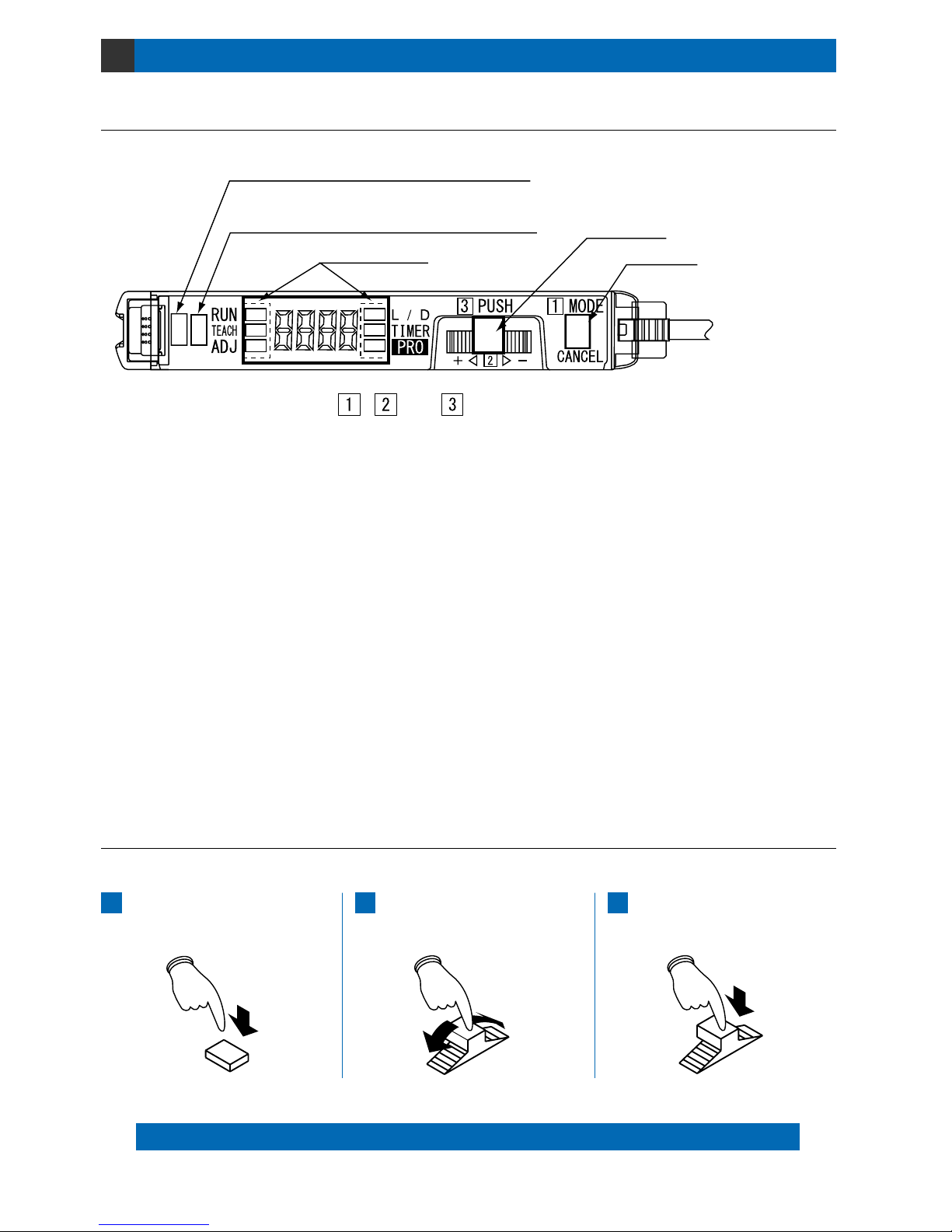
Functional Description
1-1. Functional Description
1-2. Setting Procedure
1
1 Operation indicator (Orange) … FX-301(P)(-HS) : Lights up when output is ON.
Output 1 operation indicator (Orange)…
FX-305(P) : Lights up when output 1 is ON.
2 Stability indicator (Green) …
Output 2 operation indicator (Orange)
…
3 MODE indicator … RUN (Green) :
TEACH (Yellow) :
ADJ (Yellow) :
L/D (Yellow) :
TIMER (Yellow) :
PRO (Yellow) :
4 Jog switch … Turning this switch in the ‘’ or ‘’ direction, allows different items to be viewed for
selection and pressing the switch then confirms the selected setting.
5 MODE key …
This key is used to select operating modes and to cancel settings during the configuration process.
The [MODE key] and [Jog switch] are utilized to configure various settings.
Cancel: If the [MODE key] is pressed, the unit will return to the previous settings status, immediately before the
[Jog switch] was pressed (the selected setting has been confirmed).
Selection and confirmation of settings are performed according to the order of the numbers, as shown on the amplifier: 1, 2 and 3.
Press the [MODE key]
(mode selection / cancellation)
1
Turn the [Jog switch] in the ‘’ or ‘’ direction
(chooses setting for selection)
2
Press the [Jog switch]
(confirms the selected setting)
3
1FX-301(P)(-HS): Operation indicator (Orange)
FX-305(P): Output 1 operation indicator (Orange)
2FX-301(P)(-HS): Stability indicator (Green)
FX-305(P): Output 2 operation indicator (Orange)
3MODE indicator
4Jog switch
5MODE key
, and are in the correct order for selecting settings.
Lights up during normal sensing operation.
When this indicator lights up, the ‘threshold value’ can be set by
utilizing either ‘2-level teaching’, ‘limit teaching’ or ‘full-auto teaching’.
When the FX-305(P) is in window comparator mode, the ‘threshold
value’ can be set by either ‘1-level teaching’, ‘2-level teaching’ or
‘3-level teaching’ whenever this indicator lights up.
When this indicator lights up, fine adjustment of the ‘threshold value’
can be performed.
When this indicator lights up, the output operation can be set.
When this indicator lights up, timer operation can be set.
(Timer period can be set in PRO1 mode.)
When this indicator lights up, further advanced functions, such as the
copying and memory functions, can be set.
FX-301(P)(-HS) :
Lights up when the incident light intensity is great enough for stable operation.
FX-305(P) : Lights up when output 2 is ON.
1
Phone: 800.894.0412 - Fax: 888.723.4773 - Web: www.clrwtr.com - Email: [email protected]
Page 3
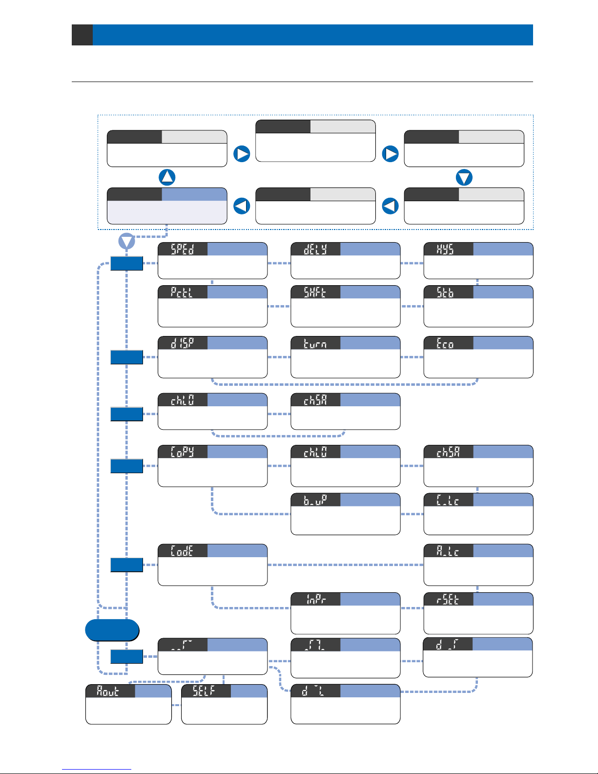
Diagram of Functions and Settings
2-1. Diagram of Functions and Settings
2
The amplifier features and settings are generally classified into two main modes; the ‘NAVI mode’ for items and
settings that are frequently reconfigured, and the ‘PRO mode’ that contains more detailed settings.
Allows fine adjustment of the
‘threshold value’. (Refer to p.19~)
Adjust
ADJ
The ‘threshold value’ can be set by utilizing
either ‘2-level teaching’, ‘limit teaching’ or
‘full-auto teaching’. (Refer to p.10~)
This indicates normal sensing
operation.
Run
RUN
NAVI
mode
PRO
mode
Sets output operation either LightON, or Dark-ON. (Refer to p.22)
L-ON / D-ON
L/D
Configures operation of the timer.
(Refer to p.23)
Timer
TIMER
Switches among response
times. (Refer to p.27)
Response Time Change
Configures timer operation.
(Refer to p.28~)
Timer Setting
Sets hysteresis level.
(Refer to p.31)
Hysteresis
Teaching
TEACH
PRO1
PRO2
PRO3
PRO4
PRO5
Shifts the ‘threshold value’ by a
certain percentage increment in
‘limit teaching’. (Refer to p.33)
Shift
Permits selection of stability indicator response
levels for changes in the range for lighting up.
(Refer to p.32) [FX-301(P)(-HS) only]
Stability
Changes the light emitting amount selection setting. (Refer
to p.34)
Light Emitting Amount Selection
Allows selection of different
content to be indicated in the
digital display. (Refer to p.37)
Digital Display Setting
Sets the viewing orientation of
the digital display.
(Refer to p.38)
Digital Display Inversion
Sets the digital display to turn
ON / OFF.
(Refer to p.39)
ECO Mode
Loads configuration setting from
the data bank. (Refer to p.41)
Data Bank Load
Saves configuration setting into
the data bank. (Refer to p.42)
Data Bank Save
Using optical communications, configuration
settings from the main unit are copied to
connected sub units all at once. (Refer to p.44)
Copy
Using optical communication, configuration
settings can be loaded from respective
data banks all at once. (Refer to p.45)
Remote Data Bank Load
Using optical communication, current configuration settings can be saved into respective
data banks all at once. (Refer to p.46)
Remote Data Bank Save
Allows basic configuration information
to be set in a single step, by inputting
a 4-digit code. (Refer t o p .5 1 )
Code
Allows fine adjustment of the ‘threshold
value’ to be directly performed during
RUN mode. (Refer to p.52)
Adjust Lock
All settings, except for data
bank information, revert to
factory settings. (Refer to p.53)
Reset
Switches the number of units for which
interference prevention switching is enabled.
* FX-305(P) only. (Refer to p.54)
Interference Prevention
Switching
P.24~
P.35~
P.40~
P.43~
P.49~
When using optical communication for carrying out copy /
load / save operations all at once, this function allows optical
communication to pass through the unit. (Refer to p.47)
Communication Change
To Permit / Not to Permit
Allows not to save the threshold
value, by teaching via external
input in EEPROM. (Refer to p.48)
* The FX-301(P)-HS is not
equipped with a PRO4
setting function.
Backup
The items that can be set are different for output 1 and output 2.
P.55~
Output 1
Output 2
Sets a threshold value for ON /
OFF operation. (Refer to p.56)
Normal Mode
Judges if set two threshold values are within the
required range or not. This can be selected in
1-level / 2-level / 3-level teaching. (Refer to p.56)
Window Comparator Mode
Sensing mode that cancels out slight changes in
light intensity so that only sudden increases in
incident light intensity are sensed. (Refer to p.56)
Rising Differential Mode
PRO6
Trailing Differential Mode
Sensing mode that cancels out slight changes in
light intensity so that only sudden decreases in
incident light intensity are sensed. (Refer to p.56)
Error Output
Output when overcurrent occurs or when
a communication error occurs from
connected incompletely. (Refer to p.58)
Alarm Output
Be used as alarm output when the threshold
value for output 2 is linked to output 1 and
the light amount drops. (Refer to p.58)
Available only
in FX-305(P)
*
When the FX-305(P) is in window comparator mode,
the ‘threshold value’ can be set by either ‘1-level
teaching’, ‘2-level teaching’ or ‘3-level teaching’.
Allows various detailed settings to be configured, such as
optical communications, save / load and other settings.
Pro
PRO
2
Phone: 800.894.0412 - Fax: 888.723.4773 - Web: www.clrwtr.com - Email: [email protected]
Page 4
Others
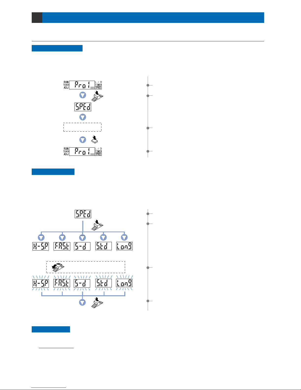
3-1. Precautions When Selecting Settings
3
Press the MODE
key once.
Example: When operating in PRO mode.
Press the Jog
switch.
To cancel
Canceling operations
1Select ‘PRO mode’.
To cancel any operation, press the [MODE key]. If the [MODE key] is pressed once, the unit will return to
the previous settings status immediately before the [Jog switch] was pressed.
When changing the status of any setting, ensure that the selected setting is subsequently confirmed.
If confirmation is not performed, the new setting will not take effect.
Confirming settings
Example: When setting response time change.
(In case of FX-301)
S-D
( reduced intensity )
STD
(standard)
H-SP
(ultra high-speed)
FAST
(high-speed)
LONG
(long-range)
Press the
Jog switch.
Press the
Jog switch.
The digital display will quickly blink 3 times to
confirm the setting.
2If the [Jog switch] is pressed, the current mode
will be displayed.
* The factory setting is ‘STD (standard)’.
4If the [Jog switch] is pressed, the digital display
will quickly blink 3 times, confirming the setting.
Setting protection
1Select ‘response time change’.
2If the [Jog switch] is pressed once, the unit will enter
the ‘response time change’ state.
3If the [Jog switch ] is turned, the digital display
will blink.
Select the desired mode.
3To cancel the ‘response time change’ operation,
press the [MODE key] once.
4The display will return to the previous [PRO1 mode]
selection screen.
You can use the ‘key lock function’ to protect settings. (Refer to p.59.)
Key lock function
This function can be used to prevent the operator from accidentally changing the sensor settings.
Turn the Jog switch to select
the desired mode.
3
Phone: 800.894.0412 - Fax: 888.723.4773 - Web: www.clrwtr.com - Email: [email protected]
Page 5
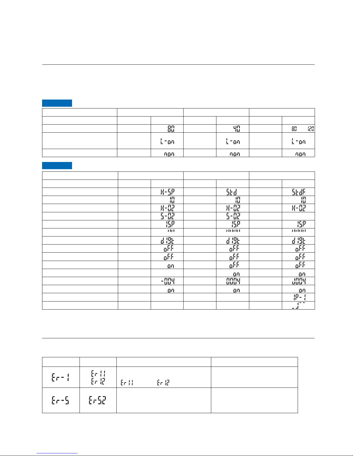
3-2. Factory Settings
Factory settings for the FX-301(P)(-HS)/305(P) are indicated below:
If the unit is reset using the ‘9-4 Setting Reset Function’ from ‘PRO5 Mode’ on p.53, the resulting settings will be
those indicated below:
Output 1:
,
Output 2:
Model No.
Item
Response time
Timer period
Hysteresis
Stability
Shift amount during limit teaching
Light emitting amount selection function
Display
Display turning
ECO mode
Selection for transmission change to permit / not to permit
Backup
Code
Adjust lock
Interference prev ention s witching function [FX-305(P) only]
Sensing mode [FX-305(P) only] (Note)
Settings
Standard (standard)
10 ms
H-02 (standard)
S-02 (standard)
15 %
Level 4 (MAX)
Incident light intensity display
OFF
OFF
OFF
ON
0004
ON
Settings
40
L-ON
Without timer
Digital display
FX-301(P)FX-301(P)-HS
Digital displaySettings
80
L-ON
Without timer
Digital display
Digital display
FX-301(P)
Error description
FX-305(P)
Measures
Turn off the power, then check the
load.
Confirm that all amplifiers are
properly connected to each other.
The load has short-circuited and excess
current is flowing.
: Output 1, : Output 2
FX-301(P)FX-301(P)-HS
FX-305(P)
FX-305(P)
Settings
Standard F (standard 2)
10 ms
H-02 (standard)
15 %
Level 4 (MAX)
Incident light intensity display
OFF
OFF
OFF
ON
J004
ON
IP-1
Normal mode
Settings
Output 1: 80, Output 2: 120
L-ON
Without timer
Digital display
Settings
H-SP (ultra high-speed)
10 ms
H-02 (standard)
S-02
(standard)
15 %
Level 2
Incident light intensity display
OFF
OFF
ON
004
ON
Digital display
NAVI mode
PRO mode
3-3. Error Display Indicator Readings
In case of errors, attempt the following measures:
Note: In window comparator mode, the factory settings for teaching method is ‘2-level teaching’.
Model No.
Item
Threshold value
Light-receiving operation
Timer operation
Communication error has occurred at
time of connection.
In case of using functions of PRO4
mode
()
(ON when light is received) (ON when light is received)(ON when light is received)
4
Phone: 800.894.0412 - Fax: 888.723.4773 - Web: www.clrwtr.com - Email: [email protected]
Page 6
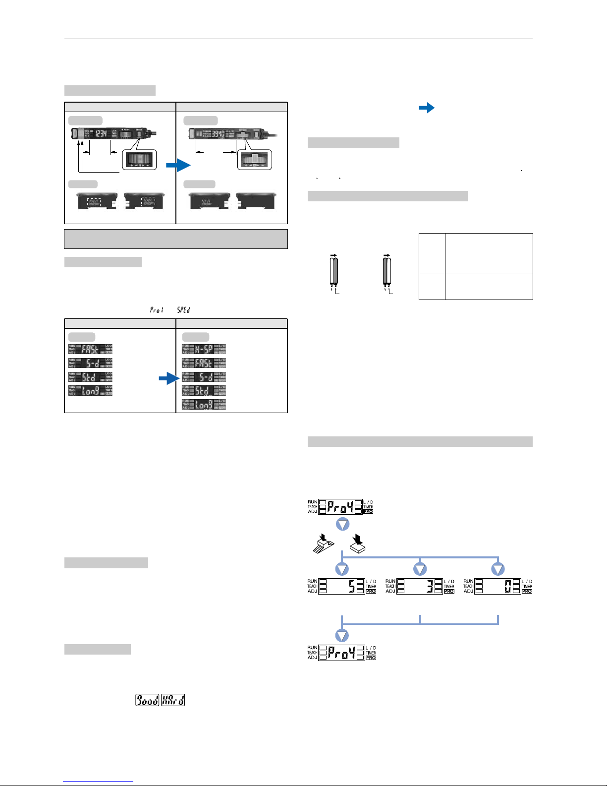
3-4. Introducing FX-301(P) Updated Version Unit
Upgraded functions
Changes in appearance
Updated version units of the FX-301(P) (red LED type) have been manufactured since June 2004. There are
some differences in the functions and communication method between these units and previous version units.
Before change After change
Top view
Side view
Name
plate
Display
Uses special parts
*
‘NAVI’ is printed on the both sides
* ‘NAVI’ is printed only on a side
Top view
Side view
Change in shape
of jog switch
Added to
name plate
Checking minor changes between previous and new models can be
done by checking whether the printing is on both sides or only one side.
An ultra high-speed mode (H-SP) has been added to the existing
4 response time modes [high-speed (FAST), reduced intensity
(S-D), standard (STD) and long range (LONG)].
This is changed using ‘ ’ in ‘ ’.
1. Response times added
Before change After change
4 steps
150 !s (FAST)
250 !s (S-D)
250 !s (STD)
2 ms (LONG)
5 steps
150 !s (FAST)
65 ¨s (added)(H-SP)
250 !s (S-D)
250 !s (STD)
2 ms (LONG)
2. Extension of timer period
The setting range for the timer period was previously 500 ms, but
this has been extended to a new range of 9999 ms.
3. Light emitting amount selection function
The light emitting amount can be changed to one of 4 levels
(5 levels when emission halt is included). However, the number of
levels that can be set will vary depending on the response time
settings. For further details, refer to p.34.
4. Backup, copy lock and key lock functions added
Backup
Copy lock
Key lock
: This selects whether or not threshold values set by
teaching are written to (stored in) an EEPROM.
: This selects whether copy function and data bank
function communication are possible or not.
: This disables input using switches to prevent
accidental changing of settings.
Digital display only
Previous version unit: Sensitivity surplus is indicated by the number
of blinks of the stability indicator.
After change
Changes in operation
1. Timer selection method
Previous version unit:
Timer type was changed using PRO1 mode. The ‘TIMER’
setting in NAVI mode could onlybe turned on or off.
After change : The type of timer can be changed using the
‘TIMER’ function in NAVI mode.
Display changes
1. Checking blinking of sensitivity margin
The stable margin display method after teaching has been changed.
2. Initial direct code value changed
The factory default settings for the direct codes have been changed.
2. Checking threshold value in RUN mode
After change: The threshold values can be checked by turning the jog switch.
Previous version unit 0000
m The default setting for the timer period is 10 ms, and the direct code for
10 ms is ‘4’, so this has been changed.
After change 0004
Internal circuit changes
1. Addition of an APC circuit
A four-chemical emitting element which provides stable sensing
over long periods has been added, as well as an APC (Auto
Power Control) circuit that improves stability during short periods.
1 Program the sensor to indicate ‘PRO4’.
2 Press the ‘jog switch’ and the ‘MODE key’
simultaneously.
3
When stop pressing the ‘jog switch’ and the ‘MODE key’,
the spec. is set and ‘PRO4’ is indicated.
The optical communications
spec. of the group B
The optical communications
spec. of the group A
Stop optical
communications
• When the units of the group A and the group B are connected in
cascade as Figure B shown above, optical communications cannot
be done. When the optical communications function is used,
connect them as Figure A shown above. If the units cannot be
placed as Figure A, the following measure 1 or 2 should be
taken.
Affix the communication window seal of the accessory amplifier
protection seal (FX-MB1) to the communication window of the
amplifier.
If the measure 1 described above cannot be taken, change the
optical communications spec. of the group B units.
1
2
Cautions on sensor connection in cascade
When the units in the group A and the group B shown in the table
below are connected in cascade, connect them in cascade as
Figure A shown below.
<Figure A><Figure B>
Optical communications
are possible
Optical communications
are impossible
Group A
Group B
Group A
Group B
•
Group A
Group B
FX-301(P): Updated version
unit, FX-305(P),
FX-301(P)-C1
FX-301(P): Previous
version unit,
FX-301G(P) / B(P) / H(P),
FX-302(P), FX-303(P),
LS-400 series (Note 1)
How to change the optical communications spec. of Group B units
Follow the procedure given below to change the optical
communications spec. of the group B units. Be sure to set the
optical communications spec. to ‘3 (the optical communications
spec. of the group A)’ or ‘0 (stop of the optical communications)’.
•
Notes:1)
When LS-400 series is connected
with the digital fiber amplifier in
cascade, be sure to locate LS-400
series at the left-most position (when
viewed from the connector side).
Every time the jog switch and the MODE key are pressed simultaneously, the indicated No. will change from ‘5’n‘0’n‘0’n‘3’n‘5’ in turn.
Notes: 2)
When the optical communications spec. is set to ‘3 (the optical communications
spec. of the group A)’, be sure to mount the units close together. Furthermore,
take care of the following.
The optical communications function may not be usable due to the environment. etc.
Do not carry out the collective channel load or save.
•
•
Notes: 3)
<Procedure to change>
5
Phone: 800.894.0412 - Fax: 888.723.4773 - Web: www.clrwtr.com - Email: [email protected]
Page 7
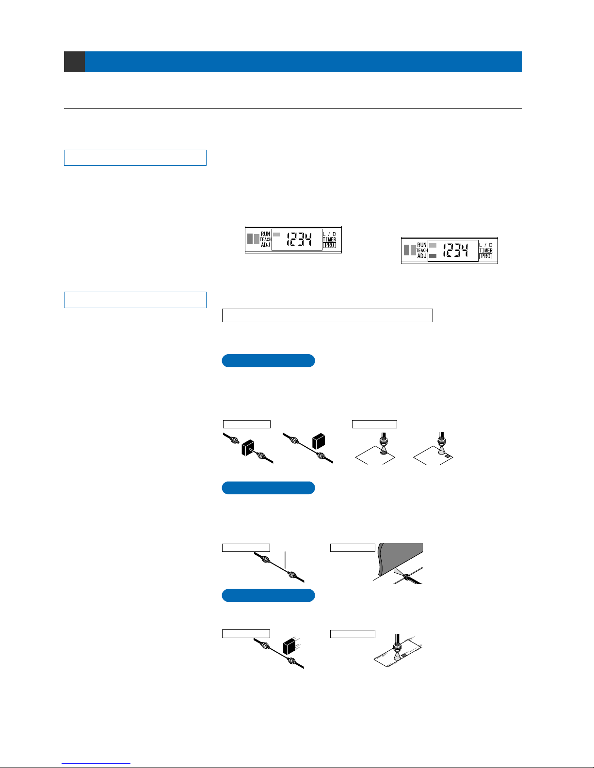
Settings for NAVI Mode
4-1. NAVI Mode Functions and Settings
4
In [NAVI mode], frequently changed settings can be easily configured.
Settings for four functions can be configured.
RUN :
Normal Sensing Operation
TEACH : Teaching Mode
This indicates normal sensing operation. Incident light intensity is displayed in real
time. The factory setting is that the ‘threshold value’ cannot be changed directly.
When the ‘Adjust Lock Function’ in ‘PRO5 Mode’ is disabled, manual fine adjustment
of the ‘threshold value’ can be performed during normal sensing operation.
The threshold value can be confirmed by turning the jog switch (Refer to p.59). In
addition, key lock function can also be set (Refer to p.59).
This mode sets the ‘threshold value’ by utilizing teaching.
When using FX-301(P)(-HS) or FX-305(P) normal mode
The ‘threshold value’ can be set with any of the 3 teaching methods, ‘2-level
teaching’, ‘limit teaching’ and ‘full-auto teaching’.
2-level teaching is a method of setting the threshold value by teaching the
amplifier unit two different status conditions - sensing object present and sensing
object absent.
The ‘threshold value’ is usually set using this method.
Sensing operation * Sensing operation when ‘threshold value’
can be fine adjusted
Refer to the section entitled ‘9-3. Adjust Lock
Function’ from ‘PRO5 Mode’ on p.52.
Refer to p.10 ~ for setting procedure
P.10
2-level Teaching
Thru-beam type Reflective type
Sensing object present Sensing object absent Sensing object present Sensing object absent
Teaches only the status condition in which no sensing object is within sensing
range (status in which incident light intensity is stable). This method is used to set
a ‘threshold value’ for conducting sensing in the presence of a background, or
when extremely small objects are to be detected.
P.11
Limit Teaching
P.12
Full-auto Teaching
This method is used to set the threshold value while the sensing objects are still
moving on the production line, without stopping the production line.
Thru-beam type
Thru-beam type
Reflective type
Reflective type
Background
Minute
object
6
Phone: 800.894.0412 - Fax: 888.723.4773 - Web: www.clrwtr.com - Email: [email protected]
Page 8

TEACH : Teaching Mode
Refer to p.13 ~ for setting procedure
P.13~
1-level Teaching
When using FX-305(P) window comparator mode
The ‘threshold value’ can be set with any of the 3 teaching methods, ‘1-level
teaching’, ‘2-level teaching’ and ‘3-level teaching’. By setting two ‘threshold
values’, both ON and OFF can occur between the two threshold value levels.
This sets the shift value to any desired value, and sets the threshold values (1_SL,
2_SL) by means of 1-level teaching.
P.15~
2-level Teaching
This carries out 2-level teaching (P-1, P-2) and sets the threshold values (1_SL,
2_SL).
ON
0
P.17~
3-level Teaching
This carries out 3-level teaching (P-1, P-2, P-3) and sets the threshold value
(1_SL) between A and B and the threshold value (2_SL) between B and C as
shown in the diagram below.
After teaching, P-1, P-2 and P-3 are automatically assigned in ascending order to
‘A’, ‘B’, and ‘C’.
Hysteresis
Output
(L-ON)
4,000 / 9,999
Incident light
intensity
ON
1_SL 2_SL
OFF
Time
Shift value
Shift value
ON
1_SL
2_SL
P-1
0
P-1
2_SL1_SL
Output
(L-ON)
Shift value
OFF
Incident light
intensity
4,000 / 9,999
Output
(L-ON)
OFF ON OFF
Time
ON
P-1
1_SL
P-2
2_SL
0
OFF
Incident light
intensity
4,000 / 9,999
Output
(L-ON)
Output
(L-ON)
P-1
1_SL
OFF ON OFF
P-2
2_SL
* In this figure, the incident
light intensity of P-1 is
less than that of P-2.
Time
ON
A
1_SL
2_SL
B
C
0
OFF
Incident light
intensity
4,000 / 9,999
Output
(L-ON)
Output
(L-ON)
P-1
1_SL
OFF ON OFF
P-2
2_SL
P-3
When using FX-305(P) differential mode
Sensing of only sudden changes in incident light intensity is carried out, so that
this is ideal for sensing edges of object such as glass.
Set to ‘full-auto teaching’ if teaching is to be carried out. (Refer to p.12 for details.)
Furthermore, if the response time has been set in STDF, LONG or U-LG mode,
mount to make the threshold values to more than the following values.
STDF mode : 40 digits
LONG mode: 60 digits
U-LG mode : 100 digits
•
•
•
7
Phone: 800.894.0412 - Fax: 888.723.4773 - Web: www.clrwtr.com - Email: [email protected]
Page 9
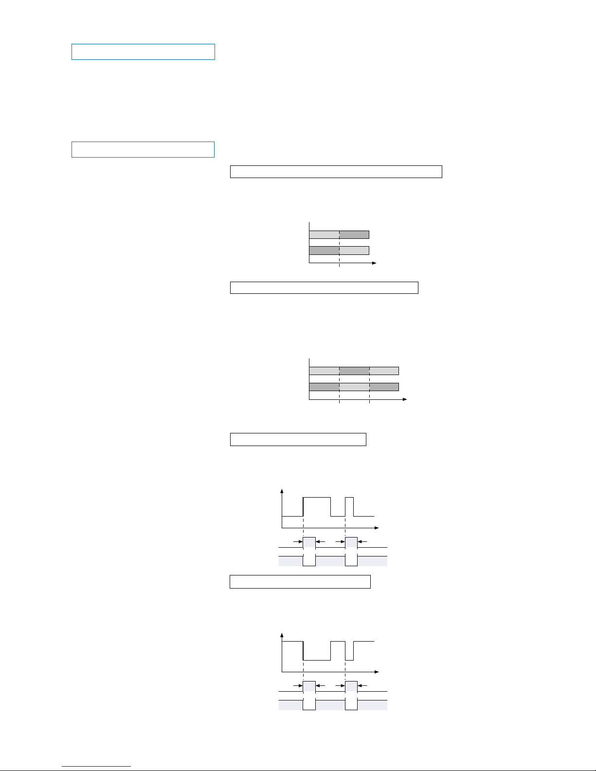
ADJ : Threshold Value Fine Adjustment Mode
This mode allows fine adjustment of the ‘threshold value’ setting.
When the incident light intensity display has been selected, the threshold value
can be adjusted in increments as low as a one digit.
When the percentage display has been selected, the threshold value can be
adjusted in increments of one digit (varies depending on the ‘threshold value’).
However, when FX-305(P) is in window comparator mode, the percentage display
function cannot be utilized.
* The factory setting is; FX-301(P): 40, FX-301(P)-HS: 80,
FX-305(P) output 1: 80, FX-305(P) output 2: 120.
Refer to p.19~ for setting procedure
0
Threshold value
Threshold
value 1
Threshold
value 2
Incident light intensity
Output operation
L-ON
D-ON
Output operation
L-ON
D-ON
* The factory setting is L-ON (Light-ON).
0
L/D: Output Operation Setting Mode
Refer to p.22 for setting procedure
When using FX-301(P)(-HS) or FX-305(P) normal mode
When using FX-305(P) window comparator mode
When set to ‘L-ON’, the output will be ON if the incident light intensity becomes
greater than the ‘threshold value’.
When set to ‘D-ON’, the output will be ON if the incident light intensity becomes
less than the ‘threshold value’.
When set to ‘L-ON’, if the incident light intensity is between the two ‘threshold
value’ levels, the output will be ON. If the incident light intensity is outside of the
two threshold value levels, the output will be OFF.
When set to ‘D-ON’, if the incident light intensity is between the two ‘threshold
value’ levels, the output will be OFF. If the incident light intensity is outside of the
two threshold value levels, the output will be ON.
This mode allows the selection of output operation from either L-ON (Light-ON), or
D-ON (Dark-ON).
When using rising differential mode
Output
operation
L-ON
Time
ON
Output
operation
L-ON
D-ON
ON
TT
OFF
When using trailing differential mode
Time
ON
OFF
OFF
ON
OFF
TT
Incident
light
intensity
Incident
light
intensity
* The output time ‘T’ can be set by changing
the timer period in timer setting mode
(initial value: 10 ms).
* The output time ‘T’ can be set by changing
the timer period in timer setting mode
(initial value: 10 ms).
For L-ON, output is ON for a constant period of time when the incident light
intensity is rising.
For D-ON, output is OFF for a constant period of time when the incident light
intensity is rising.
For L-ON, output is ON for a constant period of time when the incident light
intensity is trailing.
For D-ON, output is OFF for a constant period of time when the incident light
intensity trailing.
Incident light intensity
0 4,000 / 9,999
ONOFF
OFFON
ONOFF OFF
OFFON ON
0 4,000 / 9,999
TT
D-ON
TT
8
Phone: 800.894.0412 - Fax: 888.723.4773 - Web: www.clrwtr.com - Email: [email protected]
Page 10

PRO mode allows the configuration and usage of the following timer
operations: OFF-delay / ON-delay / ONE SHOT.
Timer period can be selected from 0.5 ms to 9,999 ms.
Please refer to the section entitled ‘5-3. Timer Setting Function [FX-301(P)(-HS)]’
from ‘PRO1 Mode’ on p.28.
PRO mode allows the configuration and usage of the following
timer
operations: OFF-delay / ON-delay / ONE SHOT / ON-delay • OFF-delay /
ONdelay • ONE SHOT.
Timer period can be selected from 0.5 ms to 9
,999 ms.
Please refer to the section entitled ‘5-4. Timer Setting Function [FX-305(P)]’
from ‘PRO1 Mode’ on p.29.
TIMER : Timer Operation Setting Mode
Refer to p.23 for setting procedure
FX-305(P)
This mode sets the timer operation and set the type of timer.
For FX-301(P)(-HS) the setting can be selected from Without timer / OFF-delay /
ON-delay / ONE SHOT timer, and the FX-305(P) includes these and also
ON-delay • OFF-delay / ON-delay • ONE SHOT timers.
FX-301(P)(-HS)
9
Phone: 800.894.0412 - Fax: 888.723.4773 - Web: www.clrwtr.com - Email: [email protected]
Page 11
10
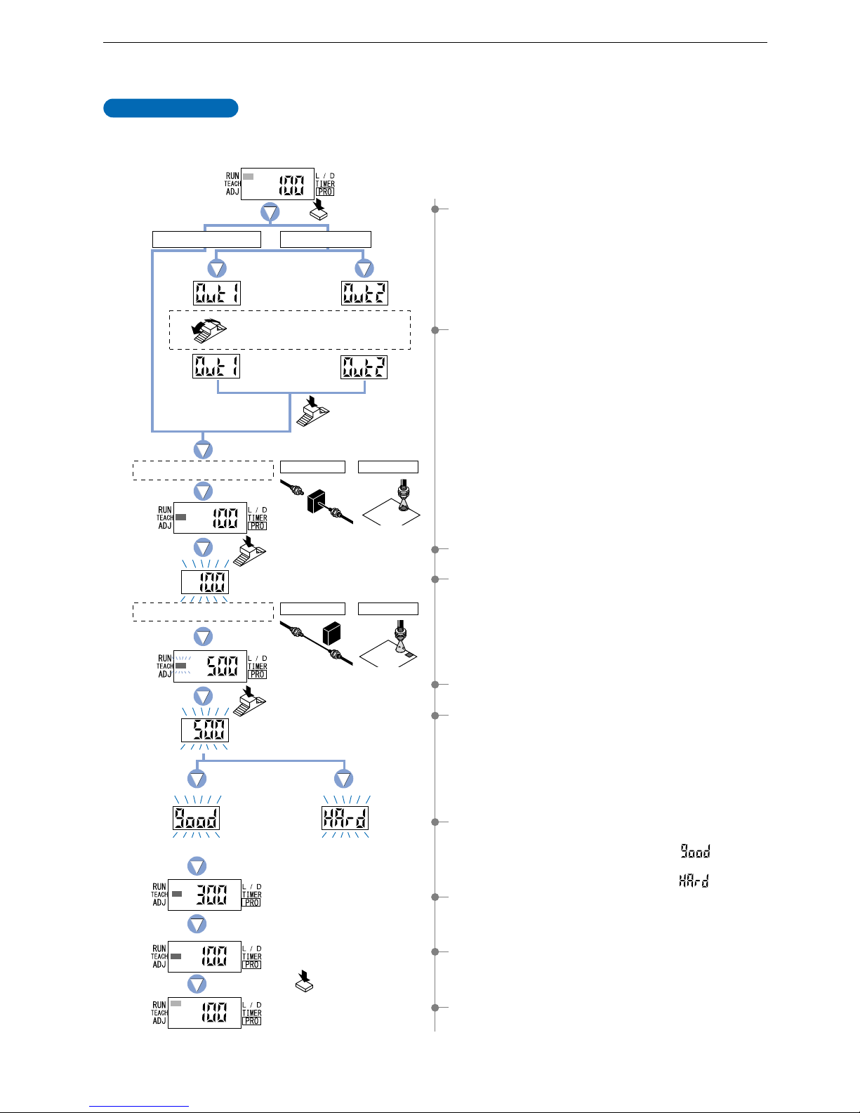
4-2. Teaching Mode [when using FX-301(P)(-HS) or FX-305(P) normal mode]
The ‘threshold value’ can be set by utilizing three kinds of teaching, whichever ‘2-level teaching’, ‘limit teaching’ or ‘full-auto teaching’.
* The factory setting is this mode for FX-305(P). (Refer to p.55)
2-level teaching is a method of setting the ‘threshold value’ by teaching the amplifier two different
status conditions - sensing object present and sensing object absent. The ‘threshold value’ is
usually set using this method.
2-level Teaching
1 Press the [MODE key] once to select ‘TEACH mode’.
3 Press the [Jog switch] when in the status condition of -
sensing object is present.
2 FX-305(P): Turn the [Jog switch] to select the desired
‘output’ for setting.
5 Press the [Jog switch] when in the status condition of -
sensing object is absent.
8 The ‘threshold value’ setting will be displayed.
9 The incident light intensity will again be displayed, indicating
that configuration is now complete.
FX-305(P): The output that has been set will be displayed.
0 Press the [MODE key] 5 times or keep it pressed for 2 sec.
or more, the amplifier will return to ‘RUN mode’ (normal
sensing operation).
4The digital display will blink and indicate the incident light
intensity reading, then the MODE indicator / TEACH
(yellow) will blink.
This indicates that the second point item is now ready for
input.
6
The digital display will again blink and indicate the incident light intensity reading
and the ‘threshold value’ will be set to a value midway between the incident
light intensities when the sensing object is present and when it is absent. The
blinking MODE indicator / TEACH will stop blinking and continuously light up.
*
Fine adjustment of the ‘threshold value’ can be performed in the ‘4-4.
Threshold Value Fine Adjustment Mode [when using FX-301(P)(-HS) or
FX-305(P) normal mode]’ described on p.19.
()
7 The sensing stability status will be displayed.
• When stable sensing can be performed
nThe digital display will blink the word ‘ ’.
• When stable sensing cannot be performed
nThe digital display will blink the word ‘ ’.
Place a fiber within sensing range.
Turn the Jog switch to select
the desired output for setting.
Press the
MODE key once.
Press the
Jog switch.
Press the
Jog switch.
Press the
Jog switch.
Status condition - sensing object is present
Status condition - sensing object is absent
Stable sensing
Output 1 Output 2
In case of FX-301(P)(-HS)
In case of FX-305(P)
Thru-beam type Reflective type
Thru-beam type Reflective type
Difference between incident light
intensities is not great enough.
Press the MODE key
5 times or keep it pressed
for 2 . or more .
Phone: 800.894.0412 - Fax: 888.723.4773 - Web: www.clrwtr.com - Email: [email protected]
Page 12
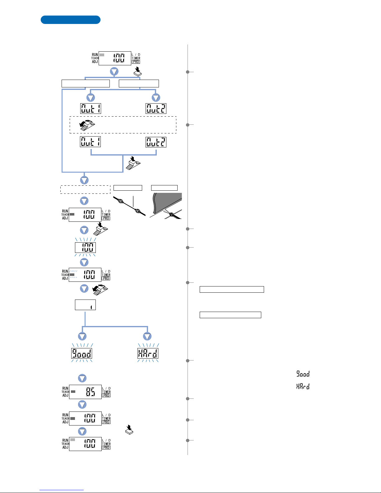
Teaches only the status condition in which no sensing object is within sensing range (status in
which incident light intensity is stable). This method is used to set a threshold value for
conducting sensing in the presence of a background, or when extremely small objects are to be
detected.
Limit Teaching
1 Press the [MODE key] once to select ‘TEACH mode’.
3 Press the [Jog switch] when in the status condition of -
sensing object is absent.
2 FX-305(P): Turn the [Jog switch] to select the desired
‘output’ for setting.
5 Turn the [Jog switch] in the ‘’ or ‘’ direction.
When using thru-beam fiber
When using reflective fiber
6 The sensing stability status will be displayed.
•
When stable sensing can be performed
nThe digital display will blink the word ‘ ’.
•
When stable sensing cannot be performed
nThe digital display will blink the word ‘ ’.
7 The ‘threshold value’ setting will be displayed.
•
If the switch is turned toward the ‘’ direction, the digital display will scroll
from the left to the right (twice) and the threshold value will be shifted down by
approximately 15 %, to a value lower than the incident light intensity reading.
•
If the switch is turned toward the ‘’ direction, the digital display will scroll
from the right to the left (twice) and the threshold value will be shifted up by
approximately 15 %, to a value higher than the incident light intensity reading.
*
The initial factory-set value of the shift amount is approximately 15 %.
The shift amount can be changed by utilizing the ‘5-7. Shift Function’ from ‘PRO1 Mode’,
described on p.33. (The percentage adjustment is variable from 0 % to 80 %, in increments of 5 %.)
4The digital display will blink and indicate the incident light
intensity reading, then the MODE indicator / TEACH
(yellow) will blink.
Press the
MODE key once.
Status condition - sensing object is absent
Press the MODE key
5 times or keep it pressed
for 2 sec. or more.
Turn the Jog switch
in the ‘’ or ‘’ direction.
The digital display will
scroll (twice).
Press the
Jog switch.
Stable sensing
Turn the Jog switch to select
the desired output for setting.
Press the
Jog switch.
Output 1 Output 2
Place a fiber within sensing range.
Minute
object
In case of FX-301(P)(-HS)
In case of FX-305(P)
Background
Thru-beam type Reflective type
Stable sensing cannot be performed.
9Press the [MODE key] 5 times or keep it pressed for 2 sec.
or more, the amplifier will return to ‘RUN mode’ (normal
sensing operation).
8The incident light intensity will again be displayed, indicating
that configuration is now complete.
FX-305(P): The output that has been set will be displayed.
11
Phone: 800.894.0412 - Fax: 888.723.4773 - Web: www.clrwtr.com - Email: [email protected]
Page 13
12
Stable sensing
Difference between
incident light intensities
is not great enough.
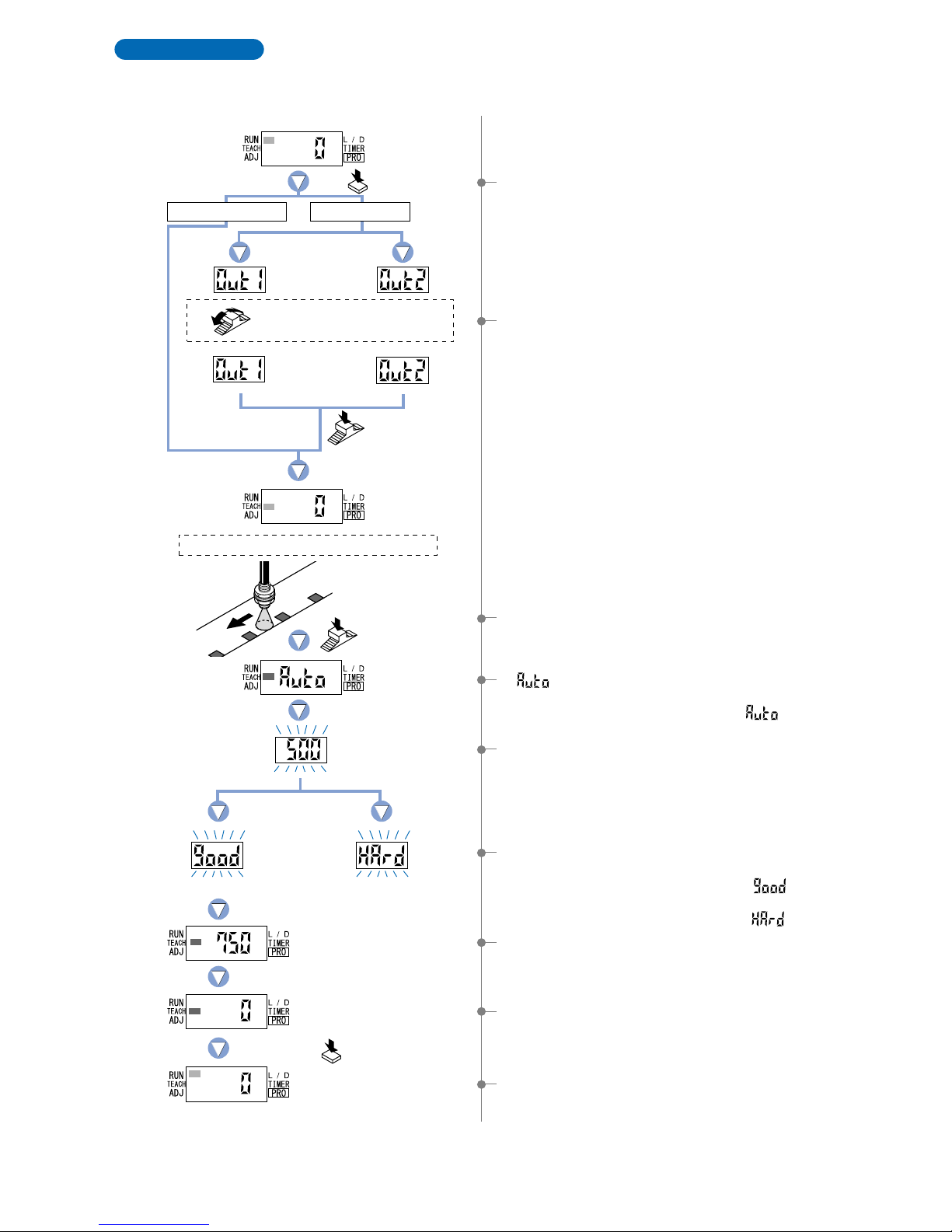
Full-auto teaching is used to set the threshould value while the sensing objects are still moving on the
production line, without stopping the production line.
* When the FX-305(P) is in differential sensing mode, set the threshold value by full-auto teaching.
(Refer to p.55)
Full-Auto Teaching
1 Press the [MODE key] once to select ‘TEACH mode’.
7The ‘threshold value’ setting will be displayed.
5The threshold value is set to a value midway between the
incident light intensities in the object present and object
absent conditions.
9Press the [MODE key] 5 times or keep it pressed for 2 sec.
or more, the amplifier will return to ‘RUN mode’ (normal
sensing operation).
8The incident light intensity will again be displayed, indicating
that configuration is now complete.
4‘ ’ is displayed on the display.
Release the jog switch when the object has passed.
* The incident light intensity is read when ‘ ’ is displayed.
3In the status condition keep the [Jog switch] pressed for
0.5 sec. or more, when the object is moving on the
production line.
2 FX-305(P): Turn the [Jog switch] to select the desired
‘output’ for setting.
6 The sensing stability status will be displayed.
• When stable sensing can be performed
nThe digital display will blink the word ‘ ’.
• When stable sensing cannot be performed
nThe digital display will blink the word ‘ ’.
Place a fiber within sensing range.
Status condition-moving the production line.
Press the MODE
key once.
Keep the Jog
switch pressed.
Press the MODE key
5 times or keep it pressed
for 2 sec. or more .
Turn the Jog switch to select
the desired output for setting.
Press the
Jog switch.
Output 1 Output 2
In case of FX-301(P)(-HS)
In case of FX-305(P)
Phone: 800.894.0412 - Fax: 888.723.4773 - Web: www.clrwtr.com - Email: [email protected]
Page 14
This is the method of setting the threshold
values (1_SL, 2_SL) by one level (P-1) teaching.
The shift value can be set as desired.
*
The shift value units can be selected from two units: ‘digit’ or ‘%’.
*
The shift value of the factory setting is set to ‘100’ of ‘digit’ units.
To set the shift value, refer to the section entitled ‘10-2. Output
1 Sensing Mode Settings’ from ‘PRO6 Mode’ on p.56.
1Press the [MODE key] once to select ‘TEACH mode’.
2Press the [Jog switch] to select ‘output 1’.
4-3. Teaching Mode [when using FX-305(P) window comparator mode]
1-level Teaching
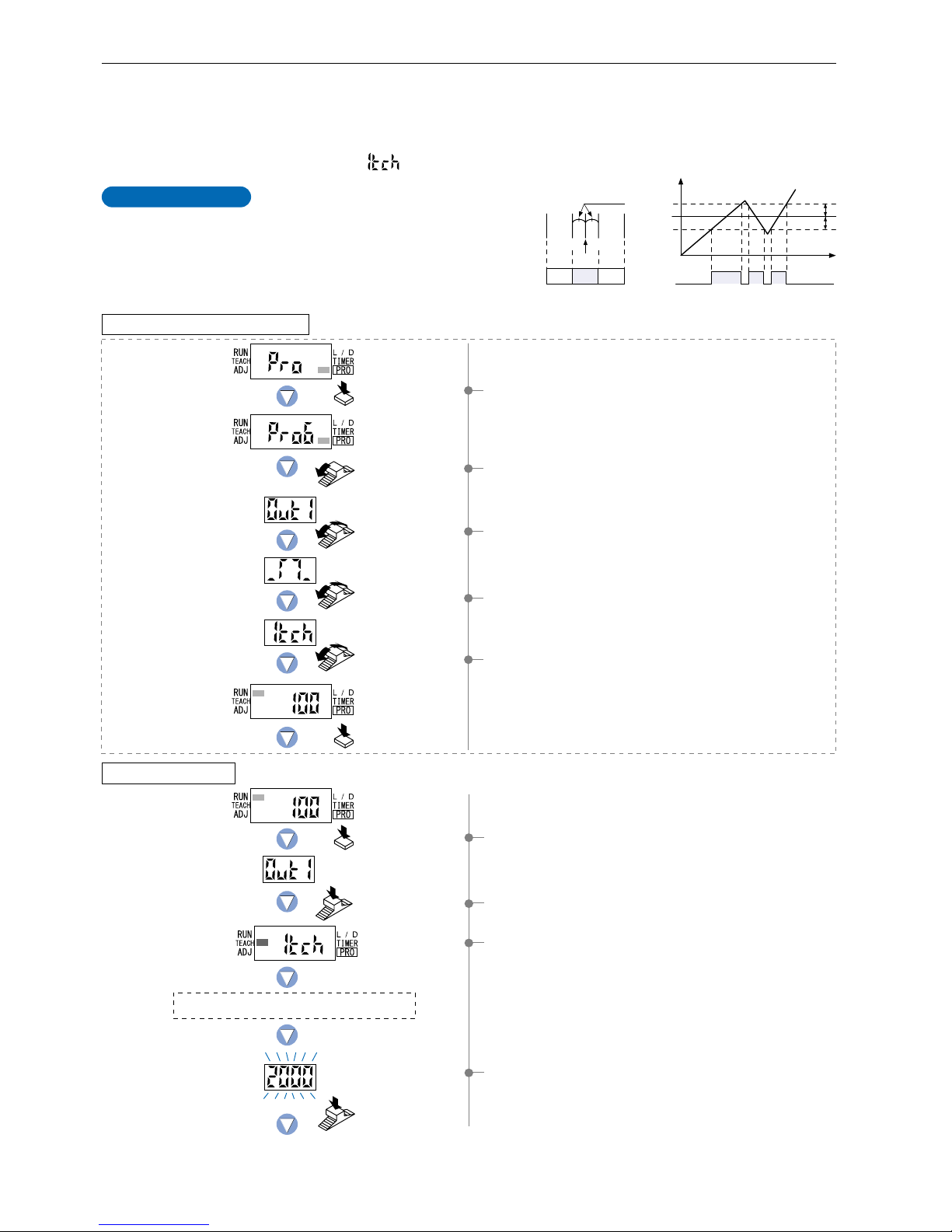
The ‘threshold value’ can be set using ‘1-level teaching’, ‘2-level teaching’ or ‘3-level teaching’. When FX-305(P) is in window
comparator mode, teaching is performed using the teaching methods described in the section entitled ‘10-2. Output 1 Sensing Mode
Settings’ from ‘PRO6 Mode’ on p.56. To change the teaching method, follow the procedures also described under the same heading.
* Window comparator mode can be set for output 1 only.
* The factory setting is ‘1-level teaching ( )’.
3The current teaching method will be displayed for 0.5 sec.,
and then the unit will enter the ‘P-1’ setting state.
1Press the [MODE key] 5 times to select ‘PRO mode’.
2Turn the [Jog switch] 6 times towards the ‘
’ direction to
select ‘PRO mode’.
3Turn the [Jog switch] to select ‘output 1’, and then press the
[Jog switch] to confirm the setting.
4Turn the [Jog switch] to select ‘window comparator mode’,
and then press the [Jog switch] to confirm the setting.
5Turn the [Jog switch] to select ‘1-level teaching’, and then
press the [Jog switch] to confirm the setting.
4If the [Jog switch] is pressed while in the status condition
when a sensing object is present that can be used as a
baseline, then the display will blink and indicate the incident
light intensity reading.
Time
Shift value
Shift value
1_SL
2_SL
P-1
0
Incident light
intensity
9,999
Output
(L-ON)
P-1
2_SL1_SL
Output
(L-ON)
Shift value
OFF ON OFF
ON
OFF
For further details, refer to ‘10-2. Output 1 Sensing Mode Settings’ on p.56.
The status condition when a sensing object is
present that can be used as a baseline.
Setting in PRO6 mode beforehand
Setting in NAVI mode
Incident light
intensity of P-1.
Press the
Jog switch.
Press the
Jog switch.
Turn the Jog switch
6 times toward the
‘’ direction.
Turn the Jog switch
to select output 1.
Press the
MODE key once.
Press the MODE key
3 times or keep it pressed
for 2 sec. or more .
Output 1
Press the
MODE key 5 times.
Turn the Jog switch
to select window
comparator mode.
Turn the Jog switch
to select 1-level
teaching.
To be continued on the next page
13
Phone: 800.894.0412 - Fax: 888.723.4773 - Web: www.clrwtr.com - Email: [email protected]
Page 15

14
Press the MODE key 5 times
or keep it pressed for 2 sec.
or more.
9Press the [MODE key] 5 times or keep it pressed for 2 sec.
or more, the amplifier will return to ‘RUN mode’ (normal
sensing operation).
6The setting for ‘lower limit value 1_SL’ will be displayed.
7The setting for ‘upper limit value 2_SL’ will be displayed.
5The display will indicate whether the upper and lower
threshold value limits have been correctly set or not.
• If ‘ ’ is blinking…the upper and lower limits have
been set correctly.
• If ‘ ’ is blinking…the upper and lower limits have
not been set correctly.
* The factory setting for shift value is ‘100’.
To set the shift value, refer to the section entitled
‘10-2. Output 1 Sensing Mode Settings’ from ‘PRO6 Mode’
on p.56.
8The output 1 will again be displayed, indicating that
configuration is now complete.
Lower limit value 1_SL
Upper limit value 2_SL
Upper and lower limits have
not been correctly set.
Stable sensing
Phone: 800.894.0412 - Fax: 888.723.4773 - Web: www.clrwtr.com - Email: [email protected]
Page 16
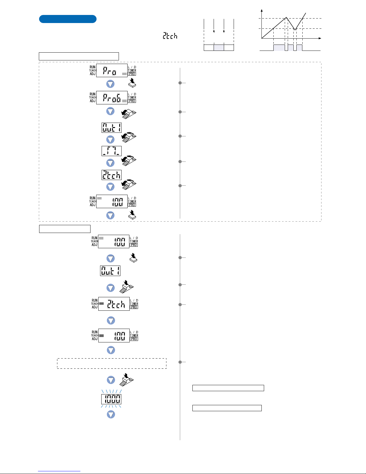
The status condition when a sensing object is present
that can be used as a baseline for the lower limit.
2-level Teaching
This is a method of setting the threshold values (1_SL, 2_SL) by two levels
(P-1, P-2) teaching.
Select ‘2-level teaching ( )’ in
PRO6 mode beforehand.
1Press the [MODE key] once to select ‘TEACH mode’.
2Press the [Jog switch] to select ‘output 1’.
3The current teaching method will be displayed, and then the
unit will enter the ‘P-1’ setting state.
4If the [Jog switch] is pressed while in the status condition
when a sensing object is present that can be used as a
baseline for the lower limit, then the display will blink and
indicate the incident light intensity reading.
When using thru-beam type fiber
• Press the [Jog switch] for the sensing object that has the
greatest amount of interrupted light.
When using reflective type fiber
• Press the [Jog switch] for the sensing object with the
lowest incident light intensity.
Note) Even if procedures 4 and 6 are reversed, teaching for a
sensing object with low incident light intensity will
automatically cause the setting of ‘lower limit value 1_SL’.
Time
ON
P-1
1_SL
P-2
2_SL
0
OFF
Incident light intensity
9,999
Output
(L-ON)
P-1
1_SL
OFF ON OFF
P-2
2_SL
Output
(L-ON)
Turn the Jog switch
6 times toward the
‘’ direction.
Turn the Jog switch
to select output 1.
Press the MODE key
3 times or keep it pressed
for 2 sec. or more .
Press the
MODE key 5 times.
Turn the Jog switch
to select window
comparator mode.
Turn the Jog switch
to select 2-level
teaching.
1Press the [MODE key] 5 times to select ‘PRO mode’.
2Turn the [Jog switch] 6 times towards the ‘’ direction to
select ‘PRO mode’.
3Turn the [Jog switch] to select ‘output 1’, and then press
the [Jog switch] to confirm the setting.
4Turn the [Jog switch] to select ‘window comparator mode’,
and then press the [Jog switch] to confirm the setting.
5Turn the [Jog switch] to select ‘2-level teaching’, and then
press the [Jog switch] to confirm the setting.
For further details, refer to ‘10-2. Output 1 Sensing Mode Settings’ on p.56.
Setting in PRO6 mode beforehand
Setting in NAVI mode
Press the
MODE key once.
Incident light
intensity of P-1.
Press the
Jog switch.
Press the
Jog switch.
Output 1
To be continued on the next page
15
Phone: 800.894.0412 - Fax: 888.723.4773 - Web: www.clrwtr.com - Email: [email protected]
Page 17
16
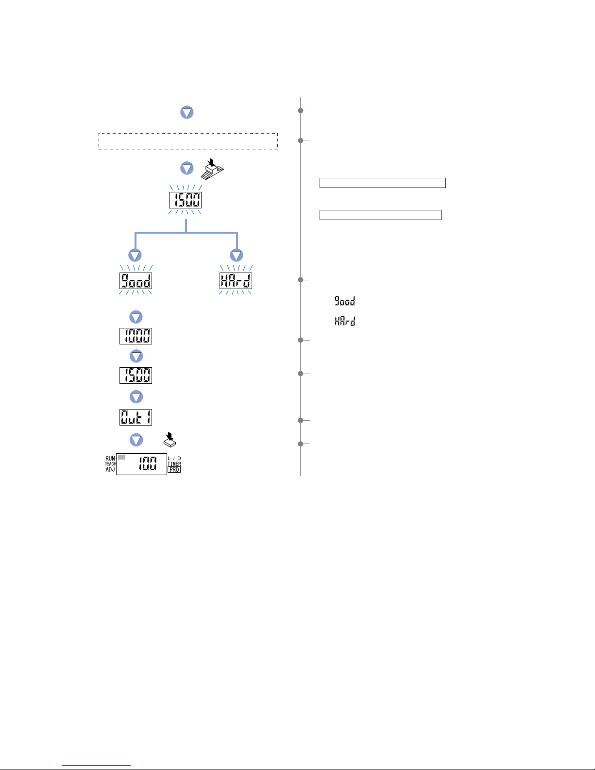
The status condition when a sensing object is present
that can be used as a baseline for the upper limit.
Upper and lower limits have
not been correctly set.
8The setting for ‘lower limit value 1_SL’ will be displayed.
9The setting for ‘upper limit value 2_SL’ will be displayed.
0The output 1 will again be displayed, indicating that
configuration is now complete.
APress the [MODE key] 5 times or keep it pressed for 2 sec.
or more, the amplifier will return to ‘RUN mode’ (normal
sensing operation).
Press the MODE key 5 times
or keep it pressed for 2 sec.
or more.
6If the [Jog switch] is pressed while in the status condition
when a sensing object is present that can be used as a
baseline for the upper limit, then the display will blink and
indicate the incident light intensity.
When utilizing thru-beam type fiber
• Press the [Jog switch] for the sensing object that has the
least amount of interrupted light.
When utilizing reflective type fiber
• Press the [Jog switch] for the sensing object with the
greatest incident light intensity .
5The unit will enter the ‘P-2’ setting state and ‘TEACH’ (yellow)
will blink on the MODE display.
7The display will indicate whether the upper and lower limits
have been correctly set or not.
• If ‘ ’ is blinking… the upper and lower limits have
been set correctly.
• If ‘ ’ is blinking… the upper and lower limits have not
been set correctly.
Incident light
intensity of P-2.
Lower limit value 1_SL
Upper limit value 2_SL
Press the
Jog switch.
Stable sensing
Phone: 800.894.0412 - Fax: 888.723.4773 - Web: www.clrwtr.com - Email: [email protected]
Page 18
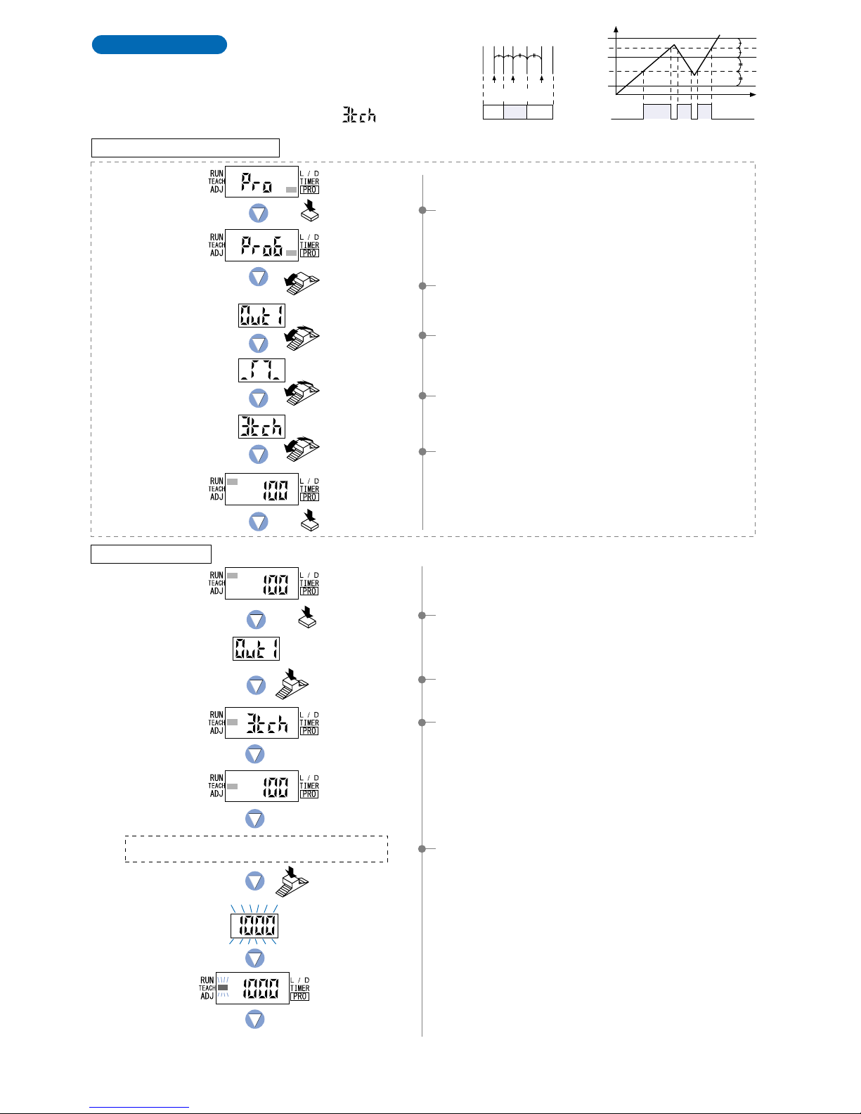
3-level Teaching
This is a method of setting the threshold range by three
levels (P-1, P-2, P-3) teaching and set the threshold values
at the middle of ‘A’ and ‘B’ (1_SL) and ‘B’ and ‘C’ (2_SL).
After teaching, P-1, P-2 and P-3 are automatically
assigned in ascending order to ‘A’, ‘B’, and ‘C’.
Select ‘3-level teaching ( )’ in PRO6 mode
beforehand.
The status condition when sensing object ‘A’ is present
that has the lowest incident light intensity.
1Press the [MODE key] once to select ‘TEACH mode’.
2Press the [Jog switch] to select ‘output 1’.
3The current teaching method will be displayed, and then the
unit will enter the ‘P-1’ setting state.
4If the [Jog switch] is pressed while in the status condition
when sensing object ‘A’ is present that has the lowest
incident light intensity, then the display will blink and indicate
the incident light intensity reading.
And then the unit will enter the ‘P-2’ setting state and
‘TEACH’ (yellow) will blink on the MODE display.
Note) ‘P-1’, ‘P-2’ and ‘P-3’ are set in that order even if
procedures 4, 5 and 6 are changed around.
Output
(L-ON)
Time
ON
A
1_SL
2_SL
B
C
0
OFF
Incident light
intensity 9,999
Output
(L-ON)
P-1
1_SL
OFF ON OFF
P-2
2_SL
P-3
AB C
For further details, refer to ‘10-2. Output 1 Sensing Mode Settings’ on p.56.
Setting in PRO6 mode beforehand
Turn the Jog switch
6 times toward the
‘’ direction.
Turn the Jog switch
to select output 1.
Press the MODE key
3 times or keep it pressed
for 2 sec. or more .
Press the
MODE key 5 times.
Turn the Jog switch
to select window
comparator mode.
Turn the Jog switch
to select 3-level
teaching.
1Press the [MODE key] 5 times to select ‘PRO mode’.
2Turn the [Jog switch] 6 times towards the ‘
’ direction to
select ‘PRO mode’.
3Turn the [Jog switch] to select ‘output 1’, and then press
the [Jog switch] to confirm the setting.
4Turn the [Jog switch] to select ‘window comparator mode’,
and then press the [Jog switch] to confirm the setting.
5Turn the [Jog switch] to select ‘3-level teaching’, and then
press the [Jog switch] to confirm the setting.
Setting in NAVI mode
Press the
MODE key once.
Incident light
intensity of P-1.
Press the
Jog switch.
Press the
Jog switch.
Output 1
To be continued on the next page
17
Phone: 800.894.0412 - Fax: 888.723.4773 - Web: www.clrwtr.com - Email: [email protected]
Page 19

18
5If the [Jog switch] is pressed while in the status condition
when sensing object ‘B’ is present that has an incident light
intensity in between that of sensing object ‘A’ and sensing
object ‘C’, the display will blink and indicate the incident light
intensity reading.
And then the unit will enter the ‘P-3’ setting state.
The status condition when sensing object ‘B’ is present that
has an incident light intensity in between that of sensing
object ‘A’ and sensing object ‘C’.
Upper and lower limits have
not been correctly set.
The status condition when sensing object ‘C’ is present
that has the greatest incident light intensity.
Press the MODE key 5 times
or keep it pressed for 2 sec.
or more.
0The output 1 will again be displayed, indicating that
configuration is now complete.
APress the [MODE key] 5 times or keep it pressed for 2 sec.
or more, the amplifier will return to ‘RUN mode’ (normal
sensing operation).
6If the [Jog switch] is pressed while in the status condition
when sensing object ‘C’ is present that has the greatest
incident light intensity, the display will blink and indicate the
incident light intensity reading.
8The setting for ‘lower limit value 1_SL’ will be displayed.
9The setting for ‘upper limit value 2_SL’ will be displayed.
7The display will indicate whether the upper and lower limits
have been correctly set or not.
• If ‘ ’ is blinking… the upper and lower limits have
been set correctly.
• If ‘ ’ is blinking… the upper and lower limits have not
been set correctly.
Lower limit value 1_SL
Upper limit value 2_SL
Incident light
intensity of P-3.
Press the
Jog switch.
Incident light
intensity of P-2.
Press the
Jog switch.
Phone: 800.894.0412 - Fax: 888.723.4773 - Web: www.clrwtr.com - Email: [email protected]
Page 20

4-4.
Threshold Value Fine Adjustment Mode [when using FX-301(P)(-HS) or FX-305(P) normal mode]
1 Press the [MODE key] twice to select ‘threshold value fine
adjustment mode’.
2 FX-305(P): Turn the [Jog switch] to select the desired ‘output’
for setting.
3 If the [Jog switch] is pressed, the ‘output’ will be set.
4 The current ‘threshold value’ will be displayed.
* The factory setting is;
FX-301(P): 40, FX-301(P)-HS: 80
FX-305(P) output 1: 80, FX-305(P) output 2: 120
5 If the [Jog switch] is turned toward the ‘’ or ‘’ direction,
the ‘threshold value’ will change and the new value will blink.
If an increased ‘threshold value’ is desired,
turn the [Jog switch] toward the ‘
’ direction.
If a decreased ‘threshold value’ is desired,
turn the [Jog switch] toward the ‘
’ direction.
* When using the FX-301(P) in LONG mode, it is
recommended that you set the threshold value to ‘15 digits’
or more.
7Press the [MODE key] 4 times or keep it pressed for 2 sec.
or more, the amplifier will return to ‘RUN mode’ (normal
sensing operation).
6If the [Jog switch] is pressed, the digital display will quickly
blink 3 times, confirming the setting of the currently
displayed ‘threshold value’.
In case of
turning toward
the ‘’.
Turn the Jog switch to set the
desired threshold value.
In case of
changing
threshold value
to 35.
Turn the
Jog switch.
Press the
Jog switch.
Press the MODE key
4 times or keep it pressed
for 2 sec. or more.
Turn the Jog switch to select the
desired output.
Press the
Jog switch.
Output 1 Output 2
Press the
MODE key twice.
The digital display will quickly
blink 3 times to confirm the value.
This mode allows fine adjustment of the ‘threshold value’ setting.
In case of FX-301(P)(-HS)
In case of FX-305(P)
The current
threshold
value
19
Phone: 800.894.0412 - Fax: 888.723.4773 - Web: www.clrwtr.com - Email: [email protected]
Page 21

20
4The lower limit setting ‘ ’ or the upper limit setting
‘ ’ will be displayed.
4-5.
Threshold Value Fine Adjustment Mode [when using FX-305(P) window comparator mode]
This mode allows fine adjustment of the ‘Threshold value (1_SL, 2_SL)’ setting.
1 Press the [MODE key] twice to select ‘threshold value fine
adjustment mode’.
2 Turn the [Jog switch] to set ‘output 1’.
3 Press the [Jog switch] to select ‘output 1’.
5 Turn the [Jog switch] to select ‘1_SL’. If the [Jog switch] is
pressed, the threshold value for ‘1_SL’ will be displayed.
If an increased ‘threshold value’ is desired,
turn the [Jog switch] toward the ‘
’ direction.
If a decreased ‘threshold value’ is desired,
turn the [Jog switch] toward the ‘
’ direction.
6 If the [Jog switch] is pressed, the display will blink quickly
3 times and the threshold value for ‘1_SL’ will be confirmed.
7 ‘ ’ is displayed. If the [Jog switch] is turned, then the
upper limit setting ‘ ’ will be displayed.
Turn the Jog switch to set
the desired threshold value.
Press the
Jog switch.
Press the
Jog switch.
Press the
MODE key twice.
Turn the Jog switch to select either
upper limit or lower limit.
Turn the
Jog switch.
Press the
Jog switch.
Press the
Jog switch.
Output 1
To be continued on the next page
Refer to p.21
for 2_SL settings.
Select ‘1_SL’.
Setting for 1_SL
The digital display will quickly
blink 3 times to confirm the value.
In case of
changing
threshold value
to 85.
Phone: 800.894.0412 - Fax: 888.723.4773 - Web: www.clrwtr.com - Email: [email protected]
Page 22

0 Press the [MODE key] 4 times or keep it pressed for 2 sec.
or more, the amplifier will return to ‘RUN mode’ (normal
sensing operation).
8If the [Jog switch] is pressed, the threshold
value for ‘2_SL’ will be displayed.
If an increased ‘threshold value’ is desired,
turn the [Jog switch] toward the ‘
’ direction.
If a decreased ‘threshold value’ is desired,
turn the [Jog switch] toward the ‘
’ direction.
9If the [Jog switch] is pressed, the display will blink quickly
3 times and the threshold value for ‘2_SL’ will be confirmed.
Press the MODE key
4 times or keep it pressed
for 2 sec. or more.
The digital display will quickly
blink 3 times to confirm the value.
In case of
changing
threshold value
to 125.
Turn the Jog switch to set
the desired threshold value.
Press the
Jog switch.
Press the
Jog switch.
Setting for 2_SL
21
Phone: 800.894.0412 - Fax: 888.723.4773 - Web: www.clrwtr.com - Email: [email protected]
Page 23

22
4-6. Output Operation Setting Mode
1 Press the [MODE key] 3 times to select ‘output operation
setting mode’.
4 The current setting will be displayed.
* The factory setting is ‘L-ON (Light-ON)’.
5 If the [Jog switch] is turned, the opposite setting for output
operation will blink on the display.
6
If the [Jog switch] is pressed, the digital display will blink quickly
3 times and the selected output operation will be confirmed.
2 FX-305(P): Turn the [Jog switch] to select the desired
‘output’ for setting.
3 If the [Jog switch] is pressed, the ‘output’ will be confirmed.
7 Press the [MODE key] 3 times or keep it pressed for 2 sec.
or more, the amplifier will return to ‘RUN mode’ (normal
sensing operation).
This mode allows the selection of output operation
from either L-ON (Light-ON) or D-ON (Dark-ON).
Incident
light
intensity
Threshold
value 2
(2_SL)
Threshold
value 1
(1_SL)
ONOFF OFF
OFFON ON
Output
operation
L-ON
D-ON
Incident
light
intensity
Threshold value
ONOFF
OFFON
Output
operation
L-ON
D-ON
FX-301(P)(-HS) or FX-305(P) normal mode
Output operation
FX-305(P) window comparator mode
Time
Incident light
intensity
ON
TT
OFF
Time
Incident light
intensity
ON
TT
OFF
TT
TT
Output operation
L-ON
(Light-ON)
D-ON
(Light-OFF)
ON
OFF
Output operation
ON
OFF
L-ON
(Light-ON)
D-ON
(Light-OFF)
When setting rising differential
mode for FX-305(P)
When setting trailing
differential mode for FX-305(P)
The current
setting
Press the
MODE key
3 times.
Turn the
Jog switch.
Press the
Jog switch.
Press the MODE key
3 times or keep it pressed
for 2 sec. or more.
Turn the Jog switch to select the
desired output.
Press the
Jog switch.
Output 1
The digital display will quickly
blink 3 times to confirm the selection.
In case of FX-301(P)(-HS)
In case of FX-305(P)
Output 2
Phone: 800.894.0412 - Fax: 888.723.4773 - Web: www.clrwtr.com - Email: [email protected]
Page 24

4-7. Timer Operation Setting Mode
This mode sets the timer operation. Timer period is set in PRO1 mode.
The factory settings is ‘Without timer’.
1 Press the [MODE key] 4 times to select ‘timer operation
setting mode’.
3 The current setting will be displayed.
If the [Jog switch] is turned, the timer operation on the digital
display will change and blink.
* The factory setting is ‘Without timer’.
5 If the [Jog switch] is pressed, the digital display will quickly
blink 3 times and selected ‘timer operation’ will be confirmed.
6 Press the [MODE key] twice or keep it pressed for 2 sec.
or more, the amplifier will to return to ‘RUN mode’ (normal
sensing operation).
4 Turn the [Jog switch] to select the desired setting for timer
operation.
2 FX-305(P): Turn the [Jog switch] to select the desired
‘output’ for setting.
This mode allows the configuration and usage of the following timer operations: OFF-delay / ON-delay / ONE SHOT.
Timer period can be selected from 0.5 ms to 9,999 ms.
Please refer to ‘5-3. Timer Setting Function [FX-301(P)(-HS)]’ in ‘PRO1 Mode’ on p.28.
This mode allows the configuration and usage of the following timer operations: OFF-delay / ON-delay / ONE SHOT
/ ON-delay • OFF-delay / ON-delay • ONE SHOT.
Timer period can be selected from; Output 1: 0.5 ms to 9,999 ms, Output 2: 0.5 ms to 500 ms.
Please refer to ‘5-4. Timer Setting Function [FX-305(P)]’ in ‘PRO1 Mode’ on p.29.
FX-305(P)
FX-301(P)(-HS)
Turn the Jog switch to select
the desired setting.
The current
timer operation
In case of setting
OFF-delay timer
Turn the
Jog switch.
Press the
Jog switch.
Press the MODE key
twice or keep it pressed
for 2 sec. or more.
Press the
MODE key 4 times.
Turn the Jog switch to select the
desired output.
Press the
Jog switch.
Output 1
Output 2
ON-delay •
OFF-delay
[
FX-305(P):
output 1 only
]
ONE SHOT ON-delay •
ONE SHOT
[
FX-305(P):
output 1 only
]
ON-delayOFF-delayWithout timer
The digital display will quickly
blink 3 times to confirm the setting.
In case of FX-301(P)(-HS)
In case of FX-305(P)
23
Phone: 800.894.0412 - Fax: 888.723.4773 - Web: www.clrwtr.com - Email: [email protected]
Page 25

24
PRO1 Mode
5-1. PRO1 Mode Functions and Settings
5
PRO1 mode is used mainly for configuring the details of basic settings.
: Response Time Change Function
The response times for the FX-301(P)(-HS) can be switched among five levels:
H-SP (ultra high-speed), FAST (high-speed), S-D (reduced intensity), STD (standard)
and LONG (long-range). The FX-305(P) can be switched among six levels: the same
as above without the S-D (reduced intensity) level but with STDF (standard 2) and
U-LG (ultra long-range) levels. (The switching of response times among these levels
will cause corresponding changes to the sensing range.)
* FX-301(P)(-HS):The factory setting is ‘STD (standard)’.
FX-305(P): The factory setting is ‘STDF (standard 2)’.
Note: If the interference prevention function is set to , the response time will become doubled.
Refer to p.27 for setting procedure
:
Timer Setting Function
Four different timer operations can be selected; Without timer / OFF-delay / ONdelay / ONE SHOT. The available timer periods are 0.5 ms and 1 to 9,999 ms.
* The settings allow timer operation to be switched among Without timer / OFF-
delay / ON-delay / ONE SHOT timer when in ‘NAVI mode’.
For output 1, six different timer operations can be selected: Without timer / OFFdelay / ON-delay / ONE SHOT / ON-delay • OFF-delay / ON-delay • ONE SHOT.
For output 2, four different timer operations can be selected: Without timer / OFFdelay / ON-delay / ONE SHOT.
The range of available timer periods is;
Output 1: 0.5 ms, 1 to 9,999 ms
Output 2: 0.5 ms, 1 to 500 ms
* The settings allow timer operation to be switched among Without timer / OFF-
delay / ON-delay / ONE SHOT / ON-delay • OFF-delay / ON-delay • ONE SHOT
when in ‘NAVI mode’.
Refer to p.28~ for setting procedure
P.28
P.29
FX-301(P)(-HS)
FX-305(P)
Mode
Model No.
FX-301(P)
Response time
FX-301(P)-HS
150 !s 150 !s150 !s
250 !s
FX-305(P)(Note)
250 !s250 !s 250 !s
2 ms 2 ms 2.5 ms
250 !s
(ultra high-speed)
(high-speed)
(reduced intensity)
(standard)
(standard 2)
(long-range)
(ultra long-range)
65 !s65 !s35 !s
700 !s
4.5 ms
(Ultra high-speed) : when performing sensing of ultra high-speed objects
(high-speed) : when performing sensing of high-speed objects
(reduced intensity): suitable for when the received light is saturated due to too
short a setting distance, and for delicate sensing when
sensing translucent objects, etc.
(standard) : standard setting
(standard 2) : The incident light intensity for standard settings can be set to
up to 9,999 [digit]
(long-range) : when long sensing range is required
(ultra long-range) : when a longer sensing range than for is required.
*
Phone: 800.894.0412 - Fax: 888.723.4773 - Web: www.clrwtr.com - Email: [email protected]
Page 26

Timer operation
Sensing condition
Output operation
Beam-received
Beam-interrupted
ON
OFF
ON
OFF
ON
OFF
ON
OFF
ON
OFF
ON
OFF
ON
OFF
ON
OFF
ON
OFF
ON
OFF
ON
OFF
ON
OFF
(Without timer)
L-ON
(ON-delay)
D-ON
L-ON
D-ON
L-ON
D-ON
L-ON
D-ON
L-ON
D-ON
L-ON
D-ON
(OFF-delay)
(ONE SHOT)
(ON-delay • OFF-delay)
(ON-delay • ONE SHOT)
T1
T1
T1
T1
T1
T1T2
T2
T2
T1
T1
T1
T1
T2
T1
T2
T1
T2
Available timer periods are:
FX-301(P)(-HS) Timer period T1, T20.5 ms, 1 to 9,999 ms
FX-305(P) Timer period; output 1: T1, T20.5 ms, 1 to 9,999 ms
output 2: T1, T20.5 ms, 1 to 500 ms
OFF-delay timer period
OFF-delay timer period
ON-delay timer period
ON-delay timer period
ON-delay timer period
Pulse width of ONE SHOT
Pulse width of ONE SHOT
T1 T2
* OFF-delay : Extends the output signal for a fixed period of time.
This function is useful if the output signal is so short that the connected device
cannot respond.
ON-delay : Neglects short output signals. As only long signals are extracted, this function
is useful for detecting if a line is clogged, or for sensing only objects taking a
long time to travel.
ONE SHOT: Outputs a fixed width signal upon sensing.
This function is useful when the input specifications of the connected device
require a signal of fixed width.
ON-delay • OFF-delay : The ON-delay and the OFF-delay timer functions can operate
simultaneously.
ON-delay • ONE SHOT: The ON-delay and the ONE SHOT timer functions can operate
simultaneously.
: Hysteresis Function
Selects the hysteresis from among three different levels (small / standard / large).
* The factory setting is ‘H-02 (standard)’.
Refer to p.31 for setting procedure
* (small) : The optimal limit of detection range
(standard) : Standard
(large) : Capability of detecting sensing objects having
a vibratory motion
: Stability Function
Permits selection from among three different stability indicator response levels
(margin width:
5 % / 10 % / 15 % ), for changes in the range of incident light.
* The factory setting is ‘S-02 (margin width:
10 %)’.
Refer to p.32 for setting procedure
Range of incident light
of stability indicator
* S-01: large range for lighting up
of stability indicator
5 %
S-02: medium range for lighting
up of stability indicator
10 %
S-03: small range for lighting up
of stability indicator
15 %
0
Light received
operation
Light interrupted
operation
Lights upLights offLight up
Incident
light margin
Output operation
Operation of stability indicator
Light interruption
margin
Incident light intensity
4,000
Threshold
value
Time chart (common to FX-301(P)(-HS)/305(P); however, only the FX-305(P) is
equipped with ON-delay / OFF-delay and ON-delay • ONE SHOT timers.
FX-301(P)(-HS) only
25
Phone: 800.894.0412 - Fax: 888.723.4773 - Web: www.clrwtr.com - Email: [email protected]
Page 27

26
: Shift Function
Shifts the ‘threshold value’ by a certain percentage increment during ‘limit teaching’.
(The percentage adjustment is variable from 0 to 80 %, in increments of 5 %).
* The factory setting is ‘15 %’.
Refer to p.33 for setting procedure
15 % higher when using reflective
type fiber (factory setting)
The threshold value is variable from
0 to 80 % (in increments of 5 %).
0
100%
15 % lower when using thru-beam
type fiber (factory setting)
If the threshold value is
shifted toward the ‘
’ direction,
minute and severe detections
become possible.
If the threshold value is
shifted toward the ‘
’ direction,
minute and severe detections
become possible.
Threshold value
When using reflective type fiber
When using thru-beam type fiber
HighLow
Limit Teaching
+
+
Emission halt
Light emitting amount Hi
Light emitting amount Lo
Level 4
Level 3
Level 2
Level 1
:
Light Emitting Amount Selection Function
Refer to p.34 for setting procedure
Changes the light emitting amount selection setting. The levels that can be
selected will vary depending on the response time.
• FX-301(P) FAST, STD, LONG: 4-levels H-SP: 3-levels S-D: 2-levels
• FX-301(P)-HS FAST, STD, LONG: 4-levels H-SP, S-D: 2-levels
• FX-305(P) FAST, STD, STDF, LONG, U-LG: 4-levels H-SP: 3-levels
Not incorporated
FX-301(P)(-HS): in H-SP and S-D mode
FX-305 : in H-SP mode
FX-301(P) : in S-D mode
FX-301(P)-HS : in H-SP and S-D mode
Phone: 800.894.0412 - Fax: 888.723.4773 - Web: www.clrwtr.com - Email: [email protected]
Page 28

Mode
Model No.
FX-301(P)
Response time
FX-301(P)-HS
150 !s 150 !s150 !s
250 !s
FX-305(P)(Note)
250 !s250 !s 250 !s
2 ms 2 ms 2.5 ms
250 !s
(ultra high-speed)
(high-speed)
(reduced intensity)
(standard)
(standard 2)
(long-range)
(ultra long-range)
65 !s65 !s35 !s
700 !s
4.5 ms
5-2. Response Time Change Function
For FX-301(P)(-HS), response time can be switched
among five levels:
H-SP (ultra high-speed) / FAST (high-speed) / S-D
(reduced intensity) / STD (standard) / LONG (long-range).
For FX-305(P), response time can be switched
among six levels:
H-SP (ultra high-speed) / FAST (high-speed) / STD (standard) /
STDF (standard 2) / LONG (long-range) / U-LG (ultra long-range).
1 Press the [MODE key] 5 times to select ‘PRO mode’.
2 Turn the [Jog switch] once toward the ‘’ direction,
to select ‘PRO1 mode’.
3 Press the [Jog switch] to enter the ‘response time
change’ state.
4 If the [Jog switch] is pressed, the current mode will be
displayed.
* FX-301(P)(-HS): The factory setting is ‘STD (standard)’.
FX-305(P): The factory setting is ‘STDF (standard 2)’.
5 If the [Jog switch] is turned, the digital display will blink.
Select the desired response time.
6 If the [Jog switch] is pressed, the digital display will
quickly blink 3 times, confirming the setting.
7 Press the [MODE key] 3 times or keep it pressed for 2 sec.
or more, the amplifier will return to ‘RUN mode’ (normal
sensing operation).
The digital display will quickly
blink 3 times to confirm the setting.
Press the MODE key
3 times or keep it
pressed for 2 sec. or
more.
S-D (reduced intensity)
STD (standard)
LONG (long-range)
Turn the Jog switch to select
the desired mode.
Press the MODE
key 5 times.
Turn the Jog switch
once toward the
‘’ direction.
Press the
Jog switch.
Press the
Jog switch.
Press the
Jog switch.
FAST (high-speed)
H-SP (ultra high-speed)
STD (standard)
STDF (standard 2)
LONG (long- range)
U-LG (ultra long-range)
FAST (high-speed)
H-SP (ultra high-speed)
In case of FX-301(P)(-HS)
In case of FX-305(P)
Turn the Jog switch to select the
desired mode.
Note: If the interference prevention function is set to , the response time will
become doubled.
27
Phone: 800.894.0412 - Fax: 888.723.4773 - Web: www.clrwtr.com - Email: [email protected]
Page 29

28
The digital display will quickly
blink 3 times to confirm the setting.
Press the MODE key
3 times or keep it
pressed for 2 sec. or
more.
5-3. Timer Setting Function [FX-301(P)(-HS)]
1 Press the [MODE key] 5 times to select ‘PRO mode’.
2 Turn the [Jog switch] once toward the ‘’ direction,
to select ‘PRO1 mode’.
3
Press the [Jog switch] to enter the ‘response time change’ state.
4 Turn the [Jog switch] once toward the ‘’ direction,
to enter the ‘timer setting’ state.
5 If the [Jog switch] is pressed, the current timer
operation will be displayed.
* The factory setting is ‘Without timer’.
6 If the [Jog switch] is turned, the digital display will blink.
Select the desired timer operation.
7 Press the [Jog switch] to enter the ‘timer period setting’ state.
* The factory setting is ‘10 ms’.
8 Turn the [Jog switch] to select the desired timer period.
* Timer period will be switched to the values set by timer
operations, unless ‘Without timer’ is chosen.
9 If the [Jog switch] is pressed, the digital display will quickly
blink 3 times, confirming the setting.
0 Press the [MODE key] 3 times or keep it pressed for 2 sec.
or more, the amplifier will return to ‘RUN mode’ (normal
sensing operation).
Four different timer operations can be selected: Without timer / OFF-delay / ON-delay / ONE SHOT.
The available timer periods are 0.5 to 9,999 ms.
* Timer selection is also possible in NAVI mode.
Turn the Jog switch to select
the desired timer operation .
Turn the Jog switch to select
the desired timer period .
Press the
Jog switch.
Press the
Jog switch.
Press the
Jog switch.
Press the
Jog switch.
Turn the Jog switch
once toward
the ‘’ direction.
Press the MODE
key 5 times.
Turn the Jog switch
once toward
the ‘’ direction.
Without
timer
OFFdelay
ONdelay
ONE
SHOT
Phone: 800.894.0412 - Fax: 888.723.4773 - Web: www.clrwtr.com - Email: [email protected]
Page 30

5-4. Timer Setting Function [FX-305(P)]
1 Press the [MODE key] 5 times to select ‘PRO mode’.
2 Turn the [Jog switch] once toward the ‘
’ direction,
to select ‘PRO1 mode’.
3 Press the [Jog switch] to enter the ‘response time change’
state.
4 Turn the [Jog switch] once toward the ‘
’ direction,
to enter the ‘timer setting’ state.
5 Turn the [Jog switch] to select the desired ‘output’ for setting.
6 If the [Jog switch] is pressed, the ‘output’ will be confirmed.
Press the MODE
key 5 times.
Turn the Jog switch
once toward
the ‘’ direction.
Turn the Jog switch
once, toward
the ‘’ direction.
Press the
Jog switch.
Press the
Jog switch.
Turn the Jog switch to select
the desired timer operation .
Press the
Jog switch.
Output 1 Output 2
To be continued on the next page
For output 1, six different timer operations can be selected: Without timer / OFF-delay / ON-delay / ONE SHOT /
ON-delay • OFF-delay / ON-delay • ONE SHOT.
For output 2, four different timer operations can be selected: Without timer / OFF-delay / ON-delay / ONE SHOT.
Available timer periods are; Output 1: 0.5 to 9,999 ms,
Output 2: 0.5 to 500 ms
29
Phone: 800.894.0412 - Fax: 888.723.4773 - Web: www.clrwtr.com - Email: [email protected]
Page 31

30
7 If the [Jog switch] is turned, the digital display will blink.
Select the desired timer operation.
* Timer selection is also possible in ‘NAVI mode’.
8 Press the [Jog switch] to enter the ‘timer period setting’ state.
* The factory setting is ‘10 ms’.
B If the [Jog switch] is pressed, the digital display will quickly
blink 3 times, confirming the setting.
0 Sets the timer period for the ON-delay timer.
A Sets the OFF-delay timer period for ON-delay • OFF-delay
timer settings, and the ONE SHOT timer period for
ON-delay • ONE SHOT timer settings.
D Press the [MODE key] 3 times or keep it pressed for 2 sec.
or more, the amplifier will return to ‘RUN mode’ (normal
sensing operation).
C The output that has been set will be displayed.
9 Turn the [Jog switch] to select the desired timer period .
When using the ON-delay • OFF-delay timer combination or
the ON-delay • ONE SHOT timer combination, each timer
can be set individually.
* Timer period will be switched to the values set by timer
operations, unless ‘Without timer’ is chosen.
Turn the Jog switch to select
the desired timer operation.
The digital display will quickly
blink 3 times to confirm the setting.
In case of
ON-delay • OFF-delay
In case of
ON-delay •
ONE SHOT
Turn the Jog switch to select
the desired timer period.
Press the
Jog switch.
Turn the Jog switch to select
the desired timer period.
Turn the Jog switch to select
the desired timer period.
Press the
Jog switch.
Press the Jog switch.
Press the MODE key
3 times or keep it
pressed for 2 sec.
or more.
Without timer
ON-delay • OFF-delay
ON-delay • ONE SHOT
OFF-delay ON-delay
ONE SHOT
When using the ON-delay • OFF-delay
timer combination or the ON-delay •
ONE SHOT timer combination
(Output 1 only) (Output 1 only)
Phone: 800.894.0412 - Fax: 888.723.4773 - Web: www.clrwtr.com - Email: [email protected]
Page 32

5-5. Hysteresis Function
This function selects the hysteresis from among three different levels (small / standard / large).
1Press the [MODE key] 5 times to select ‘PRO mode’.
2 Turn the [Jog switch] once toward the ‘’ direction,
to select ‘PRO1 mode’.
3 Press the [Jog switch] to enter the ‘response time change’
state.
4 Turn the [Jog switch] twice toward the ‘’ direction,
to enter the ‘hysteresis setting’ state.
5 If the [Jog switch] is pressed, the current
‘hysteresis’ level will be displayed.
* The factory setting is ‘H-02 (standard)’.
6 If the [Jog switch] is turned, the digital display will blink.
Select the desired ‘hysteresis’ level.
7If the [Jog switch] is pressed, the digital display will quickly
blink 3 times, confirming the ‘hysteresis’ setting.
8 Press the [MODE key] 3 times or keep it pressed for 2 sec.
or more, the amplifier will return to ‘RUN mode’ (normal
sensing operation).
The digital display will quickly
blink 3 times to confirm the setting.
H-01
(small)
H-02
(standard)
H-03
(large)
Press the MODE key
5 times.
Turn the Jog switch
once toward
the ‘
’ direction.
Press the
Jog switch.
Press the
Jog switch.
Press the
Jog switch.
Turn the Jog switch to select
the desired hysteresis.
Press the MODE key
3 times or keep it pressed
for 2 sec. or more.
Turn the Jog switch
twice toward
the ‘’ direction.
31
Phone: 800.894.0412 - Fax: 888.723.4773 - Web: www.clrwtr.com - Email: [email protected]
Page 33

32
S-01
margin
width:
5 %
S-02
margin
width:
10 %
S-03
margin
width:
15 %
The digital display will quickly
blink 3 times to confirm the setting.
5-6. Stability Function [FX-301(P)(-HS) only]
This function permits selection among three different stability indicator response levels
(margin width: 5 % / 10 % / 15 % ), for changes in the range of incident light.
1 Press the [MODE key] 5 times to select ‘PRO mode’.
2 Turn the [Jog switch] once toward the ‘’ direction,
to select ‘PRO1 mode’.
3 Press the [Jog switch] to enter the ‘response time change’
state.
4 Turn the [Jog switch] 3 times toward the ‘’ direction,
to enter the ‘stability setting’ state.
5 If the [Jog switch] is pressed, the current setting for
‘stability level’ will be displayed.
* The factory setting is ‘S-02 (margin width:
10 %)’.
6 If the [Jog switch] is turned, the digital display will blink.
Select the desired ‘stability level’.
7 If the [Jog switch] is pressed, the digital display will quickly
blink 3 times, confirming ‘stability level’ setting.
8 Press the [MODE key] 3 times or keep it pressed for 2 sec.
or more, the amplifier will return to ‘RUN mode’ (normal
sensing operation).
Press the MODE
key 5 times.
Turn the Jog switch
once toward
the ‘
’ direction.
Press the
Jog switch.
Press the
Jog switch.
Press the
Jog switch.
Turn the Jog switch to select
the desired stability level.
Press the MODE key
3 times or keep it pressed
for 2 sec. or more.
Turn the Jog switch
3 times toward
the ‘
’ direction .
Phone: 800.894.0412 - Fax: 888.723.4773 - Web: www.clrwtr.com - Email: [email protected]
Page 34

5-7. Shift Function
This function allows changing of the shift amount for the ‘threshold value’ during ‘limit teaching’.
(The percentage adjustment is variable from 0 to 80 %, in increments of 5 %.)
1 Press the [MODE key] 5 times to select ‘PRO mode’.
2 Turn the [Jog switch] once toward the ‘’ direction,
to select ‘PRO1 mode’.
3 Press the [Jog switch] to enter the ‘response time change’
state.
4 Turn the [Jog switch] 4 times toward the ‘’ direction,
to enter the ‘shift setting’ state.
5 If the [Jog switch] is pressed, the current
‘shift amount’ will be displayed.
6 If the [Jog switch] is turned, the digital display will blink.
Select the desired ‘shift amount’.
If the [Jog switch] is turned once toward the ‘’
direction, the shift amount will be
5 %.
If the [Jog switch] is turned once toward the ‘
’
direction, the shift amount will be
5 %.
The available range for the shift amount:
The percentage adjustment is variable from 0 to 80 %, in
increments of 5 %.
The digital display will quickly
blink 3 times to confirm the setting.
7 If the [Jog switch] is pressed, the digital display will quickly
blink 3 times, confirming the ‘shift amount’ setting.
8 Press the [MODE key] 3 times or keep it pressed for 2 sec.
or more, the amplifier will return to ‘RUN mode’ (normal
sensing operation).
Press the MODE
key 5 times.
Turn the Jog switch
once toward
the ‘
’ direction.
Press the
Jog switch.
Press the
Jog switch.
Press the
Jog switch.
Turn the Jog switch to select
the desired shift amount.
(
The percentage adjustment is
variable from 0 to 80 %,
in increments of 5 %.
)
Press the MODE key
3 times or keep it pressed
for 2 sec. or more.
Turn the Jog switch
4 times toward
the ‘’ direction.
5 % 5 %
33
Phone: 800.894.0412 - Fax: 888.723.4773 - Web: www.clrwtr.com - Email: [email protected]
Page 35

34
1 Press the [MODE key] 5 times to select ‘PRO mode’.
2 Turn the [Jog switch] once toward the ‘’ direction,
to select ‘PRO1 mode’.
3
Press the [Jog switch] to enter the ‘response time change’
state.
The digital display will quickly
blink 3 times to confirm the setting.
5-8. Light Emitting Amount Selection Function
This function allows changing of the light emitting amount. The levels that can be selected will vary depending on
the response time.
Press the MODE
key 5 times.
Turn the Jog switch
once toward
the ‘
’ direction.
Press the
Jog switch.
Press the
Jog switch.
Press the
Jog switch.
Press the MODE key
3 times or keep it pressed
for 2 sec. or more.
Press the Jog switch
5 times toward
the ‘’ direction.
4 Turn the [Jog switch] 5 times to enter the ‘light emitting
amount level selection’ state.
5 If the [Jog switch] is pressed, the current ‘light emitting
amount level’ will be displayed.
* FX-301(P), FX-305(P): The factory setting is ‘level 4 (MAX.)’.
FX-301(P)-HS: The factory setting is ‘level 2’.
6
If the [Jog switch] is turned, the current ‘light emitting amount level’ will be displayed.
Set to the desired ‘light emitting amount level’ from ‘light
emitting OFF’ or between ‘level 1’ and ‘level 4’.
*
The levels that can be selected will vary depending on the response time.
•
FX-301(P) FAST, STD, LONG: 4-levels H-SP: 3-levels S-D: 2-levels
•
FX-301(P)-HS FAST, STD, LONG: 4-levels H-SP, S-D: 2-levels
•
FX-305(P) FAST, STD, STDF, LONG, U-LG : 4-levels H-SP: 3-levels
7 If the [Jog switch] is pressed, the digital display will quickly
blink 3 times, confirming the ‘light emitting amount level’
setting.
8 Press the [MODE key] 3 times or keep it pressed for 2 sec.
or more, the amplifier will return to ‘RUN mode’ (normal
sensing operation).
* When the light emitting is set to OFF and the unit returns
to RUN mode (normal sensing operation), ‘ ’ will be
displayed.
Turn the Jog switch to select
the desired light emitting amount level.
Level 4 Level 1Level 2Level 3 0 %
• FX-301(P) FAST, STD, LONG: 4-levels H-SP: 3-levels S-D: 2-levels
• FX-301(P)-HS FAST, STD, LONG: 4-levels H-SP, S-D: 2-levels
• FX-305(P) FAST, STD, STDF, LONG, U-LG: 4-levels H-SP: 3-levels
Phone: 800.894.0412 - Fax: 888.723.4773 - Web: www.clrwtr.com - Email: [email protected]
Page 36

PRO2 Mode
6-1. PRO2 Mode Functions and Settings
6
PRO2 mode is used mainly for selecting the detailed configuration of the digital display.
:Digital Display Setting Function
This function allows the display to be switched among the different digital displays:
[incident light intensity display / percentage display / peak hold display / bottom
hold display / changed intensity display (Note)].
* The factory setting is ‘incident light intensity display’.
Note: For FX-305(P), when the differential mode ‘ ’ or ‘ ’ is set in PRO6 mode setting, the
changed incident light intensity is displayed.
Refer to p.37 for setting procedure
Incident light intensity display
Percentage display
Peak hold
display
Bottom hold
display
Alternating display
Alternating display
Time
2068
146
705
1820
Peak
hold
Bottom
hold
Incident light intensity
Please note that the peak hold and bottom hold values will be refreshed
consecutively.
Display Timing for Peak Hold and Bottom Hold
This function displays the
incident light intensity within
a range of 0 to 4,000.
[FX-305(P): 0 to 9,999 max.]
This function displays the incident light intensity
within a range of 1 P (1 %) to 999 P (999 %),
based on the threshold value as a reference.
This function displays the
peak numerical value of
the incident light intensity.
This function displays the
bottom numerical value of
the incident light intensity.
Display indicates the
peak value or bottom
value within the
graph area ‘ ’.
Display indicates the
peak value or bottom
value within the
graph area ‘ ’.
35
Phone: 800.894.0412 - Fax: 888.723.4773 - Web: www.clrwtr.com - Email: [email protected]
Page 37

36
:
Digital Display Inversion Function
This function can be used to invert the display orientation, according to the
direction of amplifier installation.
* The factory setting is ‘Turn OFF’.
Refer to p.38 for setting procedure
When set to ‘Turn OFF’ When set to ‘Turn ON’
:
ECO Mode Setting Function
This function turns off the digital display to reduce current consumption.
If no operations are performed for 20 sec., the letters ‘ ’ will blink and then the digital
display will turn off.
If the [MODE key] or the [Jog switch] are operated, the digital display will light up again.
*
The factory setting is ‘ECO OFF’.
Refer to p.39 for setting procedure
When set to ‘ECO OFF’ When set to ‘ECO ON’
When ECO mode is OFF:
40 mA or less (at 24 V supply voltage)
When ECO mode is ON:
25 mA or less (at 24 V supply voltage)
Current Consumption
Phone: 800.894.0412 - Fax: 888.723.4773 - Web: www.clrwtr.com - Email: [email protected]
Page 38

The digital display will quickly
blink 3 times to confirm the setting.
Press the MODE key
3 times or keep it
pressed for 2 sec. or
more.
6-2. Digital Display Setting Function
This function allows the display to be switched among the different digital displays
(incident light intensity display, percentage display, peak hold display, bottom hold display, changed intensity display).
1 Press the [MODE key] 5 times to select ‘PRO mode’.
2 Turn the [Jog switch] twice toward the ‘’ direction,
to select ‘PRO2 mode’.
3
Press the [Jog switch] to enter the ‘digital display setting’ state.
4 If the [Jog switch] is pressed, the current ‘display setting’ will
be displayed.
* The factory setting is ‘incident light intensity display’.
‘ ’ is only enabled when ‘ ’ or ‘ ’ differential mode is
selected for the FX-305(P).
5 If the [Jog switch] is turned, the digital display will blink.
Select the desired ‘display setting’.
However, when the FX-305(P) is in window comparator mode,
the percentage display function cannot be utilized.
6 If the [Jog switch] is pressed, the digital display will quickly
blink 3 times and the ‘display setting’ will be confirmed.
7 Press the [MODE key] 3 times or keep it pressed for 2 sec.
or more, the amplifier will return to ‘RUN mode’ (normal
sensing operation).
Press the MODE
key 5 times.
Turn the Jog switch
twice toward the
‘
’ direction.
Press the
Jog switch.
Press the
Jog switch.
Turn the Jog switch to select
the desired display setting.
Incident light
intensity display
Percentage
display
Peak hold
display
Bottom hold
display
Press the
Jog switch.
Changed intensity
display
[FX-305(P) only]
37
Phone: 800.894.0412 - Fax: 888.723.4773 - Web: www.clrwtr.com - Email: [email protected]
Page 39

38
The digital display will quickly
blink 3 times to confirm the setting.
Press the MODE key
3 times or keep it pressed
for 2 sec. or more.
Turn the Jog switch
once toward the
‘’ direction.
6-3. Digital Display Inversion Function
This function can be used to invert the display orientation, according to the direction of amplifier installation.
1 Press the [MODE key] 5 times to select ‘PRO mode’.
2 Turn the [Jog switch] twice toward the ‘’ direction,
to select ‘PRO2 mode’.
3
Press the [Jog switch] to enter the ‘digital display setting’ state.
4
Turn the [Jog switch] once toward the ‘’ direction,
to enter the ‘digital display inversion setting’ state.
5 If the [Jog switch] is pressed, the current ‘display orientation’
will be displayed.
* The factory setting is ‘Turn OFF’.
6 If the [Jog switch] is turned, the digital display will blink.
Select the desired ‘display orientation’.
7 If the [Jog switch] is pressed, the digital display will quickly
blink 3 times, confirming the ‘display orientation’ setting.
8 Press the [MODE key] 3 times or keep it pressed for 2 sec.
or more, the amplifier will return to ‘RUN mode’ (normal
sensing operation).
To return the display to the original state, select the
‘Turn OFF’ setting.
Press the MODE
key 5 times.
Turn the Jog switch
twice toward the
‘
’ direction.
Press the
Jog switch.
Turn OFF
In case of
Turn ON
Turn ON
Press the
Jog switch.
Press the
Jog switch.
Turn the Jog switch to select
the desired display orientation.
Phone: 800.894.0412 - Fax: 888.723.4773 - Web: www.clrwtr.com - Email: [email protected]
Page 40

Press the MODE
key 5 times.
Turn the Jog switch
twice toward the
‘
’ direction.
Press the
Jog switch.
Turn the Jog switch
twice toward the
‘’ direction.
ECO
OFF
ECO
ON
Press the
Jog switch.
Press the
Jog switch.
Turn the Jog switch to
select either ON or OFF.
No operation has been
performed for 20 sec.
Only when
ECO ON
Operating either the MODE
key or the Jog switch causes
the display to light up again.
When ECO mode is OFF:
40 mA or less (at 24 V supply voltage)
When ECO mode is ON:
25 mA or less (at 24 V supply voltage)
Current Consumption
The digital display will quickly
blink 3 times to confirm the setting.
Press the MODE key
3 times or keep it
pressed for 2 sec. or
more.
6-4. ECO Mode Setting Function
This function turns off the digital display to reduce current consumption.
If no operations are performed for 20 sec., the letters ‘ ’ will blink and then the digital display will turn off.
If the [MODE key] or the [Jog switch] are operated, the digital display will light up again.
When set to ECO OFF When set to ECO ON
1 Press the [MODE key] 5 times to select ‘PRO mode’.
2 Turn the [Jog switch] twice toward the ‘’ direction,
to select ‘PRO2 mode’.
3
Press the [Jog switch] to enter the ‘digital display setting’ state.
4 Turn the [Jog switch] twice toward the ‘’ direction, to enter
the ‘ECO mode setting’ state.
5 If the [Jog switch] is pressed, the current setting will be
displayed.
* The factory setting is ‘ECO OFF’.
6 If the [Jog switch] is turned, the digital display will blink.
Select from either ‘ECO ON’ or ‘ECO OFF’.
7 If the [Jog switch] is pressed, the digital display will quickly
blink 3 times, confirming the setting.
8Press the [MODE key] 3 times or keep it pressed for 2 sec.
or more, the amplifier will return to ‘RUN mode’ (normal
sensing operation).
0 If the [MODE key] or the [Jog switch] are operated,
the digital display will light up again.
To return the unit to the original state, select the setting
‘ECO OFF’.
9Only when the unit is set to ECO ON and no operations
are performed for 20 sec., will the letters ‘ ’ blink and
the digital display then turn off.
39
Phone: 800.894.0412 - Fax: 888.723.4773 - Web: www.clrwtr.com - Email: [email protected]
Page 41

40
PRO3 Mode
7-1. PRO3 Mode Functions and Settings
7
:
Data Bank Load Setting Function
This function allows configuration settings information from the data bank to be
selected and then loaded.
This feature allows settings to be changed quickly at times of reconfiguration, etc.
Refer to p.41 for setting procedure
:
Data Bank Save Setting Function
This function saves amplifier configuration settings.
Up to 3 sets of configuration settings information can be saved in ‘ ’,
‘ ’ and ‘ ’.
Refer to p.42 for setting procedure
Data bank
PRO3 mode can load configuration settings from the data bank and can save configuration settings to the data
bank.
The FX-301(P)(-HS) and FX-305(P) incorporate an internal memory for storing configuration information.
Three different sets of configuration settings can be stored within the data banks, in channels 1 ( ) to 3 ( ).
These configuration settings will not be deleted, unless they are intentionally overwritten by the data bank save
setting function.
Configuration information within the data bank will not be deleted, even when a reset is performed using the
‘9-4. Setting Reset Function’ from ‘PRO5 Mode’ on p.53.
(
(
(
Phone: 800.894.0412 - Fax: 888.723.4773 - Web: www.clrwtr.com - Email: [email protected]
Page 42

The digital display will blink
twice to confirm the setting.
Press the MODE key
3 times or keep it pressed
for 2 sec. or more.
7-2. Data Bank Load Setting Function
This function allows configuration settings information from the data bank to be selected and then loaded.
This feature allows settings to be changed quickly at times of reconfiguration, etc.
1 Press the [MODE key] 5 times to select ‘PRO mode’.
2 Turn the [Jog switch] 3 times toward the ‘’ direction,
to select ‘PRO3 mode’.
3 Press the [Jog switch] to enter the ‘data bank load setting’
state.
4 If the [Jog switch] is pressed, the digital display will blink.
5 If the [Jog switch] is turned, the ‘channel’ will be changed.
Select the desired ‘channel’ for loading.
6 If the [Jog switch] is pressed, the letters ‘ ’ will blink.
8 Press the [MODE key] 3 times or keep it pressed for 2 sec.
or more, the amplifier will return to ‘RUN mode’ (normal
sensing operation).
7If the [Jog switch] is pressed while ‘ ’ is blinking, the
configuration settings will be loaded from the selected
‘channel’. The digital display will blink twice, confirming the
new setting.
Turn the Jog switch to select the
desired channel for loading.
Press the MODE
key 5 times.
Press the
Jog switch.
Press the
Jog switch.
Turn the Jog switch 3 times
toward the ‘’ direction.
Press the
Jog switch.
Press the
Jog switch.
Channel 1 Channel 2 Channel 3
41
Phone: 800.894.0412 - Fax: 888.723.4773 - Web: www.clrwtr.com - Email: [email protected]
Page 43
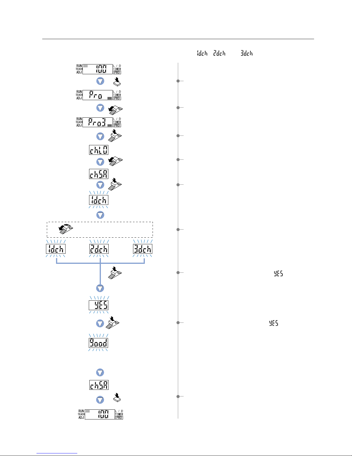
42
The digital display will blink twice
and the procedure will be complete.
Press the MODE key
3 times or keep it pressed
for 2 sec. or more.
7-3. Data Bank Save Setting Function
This function saves amplifier configuration settings.
Up to 3 sets of configuration settings information can be saved in ‘ ’ ‘ ’ and ‘ ’ .
1 Press the [MODE key] 5 times to select ‘PRO mode’.
2 Turn the [Jog switch] 3 times toward the ‘’ direction,
to select ‘PRO3 mode’.
3 Press the [Jog switch] to enter the ‘data bank load setting’
state.
4 Turn the [Jog switch] once toward the ‘’ direction,
to enter the ‘data bank save setting’ state.
5 If the [Jog switch] is pressed, the digital display will blink.
6 If the [Jog switch] is turned, the ‘channel’ will be changed.
Select the desired ‘channel’ for saving.
7 If the [Jog switch] is pressed, the letters ‘ ’ will blink.
9 Press the [MODE key] 3 times or keep it pressed for 2 sec.
or more, the amplifier will return to ‘RUN mode’ (normal
sensing operation).
8If the [Jog switch] is pressed while ‘ ’ is blinking, the
configuration settings will be saved to the selected
‘channel’. The digital display will blink twice and the
procedure will be complete.
Turn the Jog switch to select the
desired channel for saving.
Press the MODE
key 5 times.
Press the
Jog switch.
Press the
Jog switch.
Turn the Jog switch
once toward the
‘’ direction.
Press the
Jog switch.
Press the
Jog switch.
Turn the Jog switch
3 times toward the
‘’ direction.
Channel 1 Channel 2 Channel 3
Phone: 800.894.0412 - Fax: 888.723.4773 - Web: www.clrwtr.com - Email: [email protected]
Page 44

PRO4 Mode
8-1. PRO4 Mode Functions and Settings
8
PRO4 mode is used mainly for configuring the communications with sub units.
* FX-301(P)-HS is not equipped with an optical communication function, so the PRO4 mode cannot be set.
:
Setting Condition Copy Function
By utilizing the optical communications function, the settings information from the
operating amplifier can be copied to other connected units. (Except for data bank
contents) In addition, copying will not be carried out for FX-301(P) and FX-305(P)
units in which the optical communication function has been locked.
Note) It is not possible to communicate setting information between FX-301(P), FX-301B/G/H(P) and
FX-305(P) units when using the setting condition copy function. Therefore, if units of different models
need to be connected together, then units of the same model should be connected side-by-side.
Refer to p.64 for setting procedure
:
Remote Data Bank Load Setting Function
By utilizing optical communication, settings within the data banks of each connected
amplifier can be loaded all at once. However, channel data will not be loaded for
FX-301(P) and FX-305(P) units in which the optical communication setting function
has been locked. Setting information can be quickly changed during reconfiguration.
Refer to p.45 for setting procedure
:
Remote Data Bank Save Setting Function
This function allows the current configuration setting information for all connected
amplifiers to be saved into the respective data banks.
Saves on the labor required to store individual settings, one-by-one, for each amplifier. Up to 3 sets of
configuration settings information can be saved for each amplifier. However, in FX-301(P) or FX-305(P) units
in which the optical communications settings change function has been locked, information will not be saved.
Refer to p.46 for setting procedure
:
Selection for Communication Change
to Permit / Not to Permit
The optical communications function
When copying settings information from the CH4 unit to other
higher connected units: Use the copy function at the CH4 unit.
When copying settings information from the CH1 unit to other higher connected units:
Use the copy function at the CH1 unit.
Example: when 16 units are connected in the side-by-side configuration.
Direction of communication
The FX-301(P) and FX-305(P) incorporate an optical communication function. By utilizing optical communications, interference can
be prevented and configuration settings information can be copied among connected amplifiers. Optical communications can occur
only in the direction shown in the diagram below. The maximum number of communicating units is 16, including the main unit.
Also, note that optical communication cannot be used when the line settings are being changed (when indicators are blinking) and
when PRO mode is set. Be aware that sensing operations will not be possible when the optical communication feature is in use.
If using optical communication with the FX-301(P)(previous version unit) or FX-301B/G/H(P)(blue / green / infrared LED)
together with the FX-301(P)(updated version unit) or FX-305(P), optical communication may not work properly
depending on the order of connection. Refer to ‘Points to note when combining sensor types’ (P.5) for further details.
If the optical communication setting change function has been locked when attempting to carry out copy / load
/ save operations on all amplifiers at once using the setting condition copy function, remote data bank setting
function or remote data bank save setting function while in PRO mode, only the amplifier being configured will
be locked. As a result, copy / load / save operations can be carried out on except the locked units.
* The factory setting is ‘Lock OFF’.
Refer to p.47 for setting procedure
CH1 CH2 CH3 CH4 CH5 CH6 CH7 CH8 CH9 CH10 CH11 CH12 CH13 CH14 CH15 CH16
:
Backup Setting Function
This function does not store the threshold values in the EEPROM when teaching via external input.
Prevents frequent overwriting of data in the EEPROM.
* Note that when the power is turned off, the threshold values will become the
values that were last stored in memory.
Refer to p.48 for setting procedure
43
Phone: 800.894.0412 - Fax: 888.723.4773 - Web: www.clrwtr.com - Email: [email protected]
Page 45

44
The digital display will blink
twice to confirm the setting.
Press the MODE key
3 times or keep it
pressed for 2 sec. or
more.
8-2. Setting Contents Copy Function [Except FX-301(P)-HS]
By utilizing the optical communications function, the settings information from the operating amplifier can be
copied to other connected units. (Except for data bank contents) In addition, copying will not be carried out for
FX-301(P) and FX-305(P) units in which the optical communication function has been locked.
Note) It is not possible to communicate setting information between FX-301(P), FX-301B/G/H(P) and FX-305(P)
units using the setting condition copy function. Therefore, if units of different models need to be connected
together, then units of the same model should be connected side-by-side.
Please refer to p.43 The optical communications function for the direction of optical communication.
1 Press the [MODE key] 5 times to select ‘PRO mode’.
2 Turn the [Jog switch] 4 times toward the
‘’ direction, to
select ‘PRO4 mode’.
3 Press the [Jog switch] to enter the ‘setting condition copy
setting’ state.
4 If the [Jog switch] is pressed, the digital display will blink.
5If the [Jog switch] is pressed while ‘ ’ is blinking, the
digital display will scroll (twice) and the settings information
will be copied. Then ‘ ’ will blink twice, confirming the
setting.
However, for amplifiers in which the optical communications settings change function has been locked,
‘ ’ will blink twice.
* When communication error has occurred;
FX-301(P): ‘ ’ will be displayed.
FX-305(P
): ‘ ’ will be displayed.
Check that all amplifier units are properly connected to
each other.
6 Press the [MODE key] 3 times or keep it pressed for 2 sec.
or more, the amplifier will return to ‘RUN mode’ (normal
sensing operation).
Press the MODE key
5 times.
Press the
Jog switch.
Press the
Jog switch.
Press the
Jog switch.
The digital display
will scroll (twice).
Turn the Jog switch
4 times toward the
‘’ direction.
Also displayed on
amplifiers on which
copy is done
Phone: 800.894.0412 - Fax: 888.723.4773 - Web: www.clrwtr.com - Email: [email protected]
Page 46

Press the MODE
key 5 times.
Turn the Jog switch
4 times toward the
‘’ direction.
Press the
Jog switch.
Turn the Jog switch
once toward the
‘’ direction.
Press the
Jog switch.
Press the
Jog switch.
Press the
Jog switch.
The digital display
will scroll (twice).
Channel 1 Channel 2 Channel 3
Turn the Jog switch to select the desired
channel for loading for all amplifiers at once.
The digital display will blink
twice to confirm the setting.
Press the MODE key
3 times or keep it pressed
for 2 sec. or more.
Displayed on
amplifiers on which
communication is
being done.
8-3. Remote Data Bank Load Setting Function [Except FX-301(P)-HS]
By utilizing optical communication, settings within the data banks of each connected amplifier can be loaded all at
once. However, channel data will not be loaded for FX-301(P) and FX-305(P) units in which the optical
communication setting function has been locked.
Please refer to p.43 The optical communications function for the direction of optical communication.
1 Press the [MODE key] 5 times to select ‘PRO mode’.
2 Turn the [Jog switch] 4 times toward the ‘
’ direction, to
select ‘PRO4 mode’.
3 Press the [Jog switch] to enter the ‘setting condition copy
setting’ state.
4 Turn the [Jog switch] once toward the ‘
’ direction, to enter
the ‘remote data bank load setting’ state.
5 If the [Jog switch] is pressed, the digital display will blink.
6 Turn the [Jog switch] to select the desired ‘channel’ for
loading for all amplifiers at once.
7 If the [Jog switch] is pressed, the letters ‘ ’ will blink.
8If the [Jog switch] is pressed while ‘ ’ is blinking, the
digital display will scroll (twice) and the settings information
will be loaded for all amplifiers at once. Then ‘ ’ will
blink twice, confirming the setting.
However, for amplifiers [FX-301(P) or FX-305(P)] in
which the optical communications settings change
function has been locked, ‘ ’ will blink twice.
9 Press the [MODE key] 3 times or keep it pressed for 2 sec.
or more, the amplifier will return to ‘RUN mode’ (normal
sensing operation).
45
Phone: 800.894.0412 - Fax: 888.723.4773 - Web: www.clrwtr.com - Email: [email protected]
Page 47

46
Press the MODE
key 5 times.
Turn the Jog switch
4 times toward the
‘
’ direction.
Press the
Jog switch.
Turn the Jog switch
twice toward the
‘’ direction.
Press the
Jog switch.
Press the
Jog switch.
Press the
Jog switch.
The digital display
will scroll (twice).
Channel 1 Channel 2 Channel 3
Turn the Jog switch to select the desired
channel for saving for all amplifiers at once .
The digital display will blink twice
and the procedure will be complete.
Displayed on
amplifiers on which
communication is
being done.
8-4. Remote Data Bank Save Setting Function [Except FX-301(P)-HS]
This function allows the current configuration setting information for all connected amplifiers to be saved into the respective data banks.
Up to 3 sets of configuration settings information can be saved into each amplifier, using
‘ ’
,
‘ ’
and
‘ ’
.
However, units in which the optical communications settings change function has been locked, saving will not occur.
Please refer to p.43 The optical communications function for the direction of optical communication.
1 Press the [MODE key] 5 times to select ‘PRO mode’.
2 Turn the [Jog switch] 4 times toward the
‘’ direction, to
select ‘PRO4 mode’.
3 Press the [Jog switch] to enter the ‘setting condition copy
setting’ state.
4 Turn the [Jog switch] twice toward the
‘’ direction, to enter
the ‘remote data bank save setting’ state.
5 If the [Jog switch] is pressed, the digital display will blink.
6 Turn the [Jog switch] to select the desired ‘channel’ for
saving for all amplifiers at once.
7 If the [Jog switch] is pressed, the letters ‘ ’ will blink.
9Press the [MODE key] 3 times or keep it pressed for 2 sec.
or more, the amplifier will return to ‘RUN mode’ (normal
sensing operation).
Press the MODE key
3 times or keep it pressed
for 2 sec. or more.
8If the [Jog switch] is pressed while ‘ ’ is blinking, the
digital display will scroll (twice) and the settings information
will be saved for all amplifiers at once. Then ‘ ’ will
blink twice and the procedure will be complete.
However, for amplifiers in which the optical communications settings change function has been locked,
‘ ’ will blink twice.
Phone: 800.894.0412 - Fax: 888.723.4773 - Web: www.clrwtr.com - Email: [email protected]
Page 48

Turn the Jog switch to
select from either ON or OFF.
Press the MODE
key 5 times.
Turn the Jog switch
4 times toward the
‘
’ direction.
Press the
Jog switch.
Turn the Jog switch
4 times toward the
‘’ direction.
Press the
Jog switch.
Press the
Jog switch.
Press the MODE key
3 times or keep it pressed
for 2 sec. or more.
The digital display will quickly
blink 3 times to confirm the setting.
8-5. Selection for Communication Change to Permit / Not to Permit
1 Press the [MODE key] 5 times to select ‘PRO mode’.
2 Turn the [Jog switch] 4 times toward the
‘’ direction, to
select ‘PRO4 mode’.
3 Press the [Jog switch] to enter the ‘setting condition copy
setting’ state.
4 Turn the [Jog switch] 4 times toward the ‘
’ direction, to
enter the ‘selection for communication change to permit / not
to permit’.
5 If the [Jog switch] is pressed, the current setting will be
displayed.
* The factory setting is ‘Lock OFF’.
6 If the [Jog switch] is turned, the digital display will blink.
Select from either ‘ON’ or ‘OFF’.
7 If the [Jog switch] is pressed, the digital display will quickly
blink 3 times, confirming the setting.
8 Press the [MODE key] 3 times or keep it pressed for 2 sec.
or more, the amplifier will return to ‘RUN mode’ (normal
sensing operation).
If the optical communication setting change function has been locked when attempting to carry out copy / load /
save operations on all amplifiers at once using the setting condition copy function, remote data bank setting
function or remote data bank save setting function while in PRO mode, only the amplifier being configured will be
locked. As a result, copy / load / save operations can be carried out except the locked units.
47
Phone: 800.894.0412 - Fax: 888.723.4773 - Web: www.clrwtr.com - Email: [email protected]
Page 49

48
Turn the Jog switch to
select from either ON or OFF .
Press the MODE
key 5 times.
Turn the Jog switch
4 times toward the
‘
’ direction.
Press the
Jog switch.
Turn the Jog switch
5 times toward the
‘’ direction.
Press the
Jog switch.
Backup
ON
Backup
OFF
Press the
Jog switch.
Press the MODE key
3 times or keep it pressed
for 2 sec. or more.
The digital display will quickly
blink 3 times to confirm the setting.
8-6. Backup Setting Function
1 Press the [MODE key] 5 times to select ‘PRO mode’.
2 Turn the [Jog switch] 4 times toward the
‘’ direction, to
select ‘PRO4 mode’.
3 Press the [Jog switch] to enter the ‘setting condition copy
setting’ state.
4 Turn the [Jog switch] 5 times toward the ‘
’ direction, to
enter the ‘backup ON / OFF setting’ state.
5 If the [Jog switch] is pressed, the current setting will be
displayed.
* The factory setting is ‘Backup ON’.
6 If the [Jog switch] is turned, the digital display will blink.
Select from either ‘Backup ON’ or ‘Backup OFF’.
7 If the [Jog switch] is pressed, the digital display will quickly
blink 3 times, confirming the setting.
8 Press the [MODE key] 3 times or keep it pressed for 2 sec.
or more, the amplifier will return to ‘RUN mode’ (normal
sensing operation).
When using units such as the FX-CH2, this function does not store the threshold values in the EEPROM when
teaching via external input. This prevents frequent overwriting of data in the EEPROM.
Phone: 800.894.0412 - Fax: 888.723.4773 - Web: www.clrwtr.com - Email: [email protected]
Page 50

Output 1 only can be set.
[FX-301(P)(-HS) Code Setting Table]
STD
STD
STD
LONG
LONG
LONG
FAST
FAST
FAST
S-D
H-02 (standard)
H-03 (large)
H-01 (small)
H-02 (standard)
H-03 (large)
H-01 (small)
H-02 (standard)
H-03 (large)
H-01 (small)
H-02 (standard)
Direct
code
Check Check Check
Check
First digit
Response
Time
Hysteresis
Direct
code
L-ON
L-ON
L-ON
L-ON
D-ON
D-ON
D-ON
D-ON
L-ON / D-ON
Incident light intensity
%
Peak hold
Bottom hold
Incident light intensity
%
Peak hold
Bottom hold
Second digit
Display
Direct
code
ON
ON
ON
ON
OFF
OFF
OFF
OFF
NON (without timer)
OFF-delay
ON-delay
ONE SHOT
NON (without timer)
OFF-delay
ON-delay
ONE SHOT
Third digit
Adjust
lock
Timer operation
OFF
1 ms
3 ms
5 ms
10 ms
30 ms
50 ms
100 ms
300 ms
500 ms
1 sec.
2 sec.
3 sec.
4 sec.
5 sec.
Direct
code
Fourth digit
Timer
period
[FX-305(P) Code Setting Table]
STD
STD
STD
LONG
LONG
LONG
FAST
FAST
FAST
H-SP
U-LG
STDF
H-02 (standard)
H-03 (large)
H-01 (small)
H-02 (standard)
H-03 (large)
H-01 (small)
H-02 (standard)
H-03 (large)
H-01 (small)
H-02 (standard)
H-02 (standard)
H-02 (standard)
Direct
code
Check Check Check
Check
First digit
Response
Time
Hysteresis
Direct
code
L-ON
L-ON
L-ON
L-ON
D-ON
D-ON
D-ON
D-ON
L-ON / D-ON
Incident light intensity
%
Peak hold
Bottom hold
Incident light intensity
%
Peak hold
Bottom hold
Second digit
Display
Direct
code
ON
ON
ON
ON
OFF
OFF
OFF
OFF
ON
ON
OFF
OFF
NON (without timer)
OFF-delay
ON-delay
ONE SHOT
NON (without timer)
OFF-delay
ON-delay
ONE SHOT
ON-delay • OFF-delay
ON-delay • ONE SHOT
ON-delay • OFF-delay
ON-delay • ONE SHOT
Third digit
Adjust
lock
Timer operation
OFF
1 ms
3 ms
5 ms
10 ms
30 ms
50 ms
100 ms
300 ms
500 ms
1 sec.
2 sec.
3 sec.
4 sec.
5 sec.
Direct
code
Fourth digit
Timer
period
* In the event that the timer operation for ON-delay / OFF-delay or
ON-delay / ONE SHOT (8~b) are both set using the 3rd digit, then
the timer period setting selected by the 4th digit will be common to
both timer operations.
PRO5 Mode
9-1. PRO5 Mode Functions and Settings
9
Direct Code
PRO5 mode allows the input of direct codes and adjust lock functions.
It also permits the unit to be reset (re-initialized).
Furthermore, the interference prevention function can be set for FX-305(P).
FX-301(P)(-HS) and FX-305(P) contain certain encoded basic configuration information that can be set by inputting a 4-digit code.
The functions that may be set using direct coding are: Response time, Hysteresis, L-ON / D-ON, Display setting,
Adjust lock setting function, Timer operation and Timer period.
:
Code Setting Function
The following input of a 4-digit code allows the configuration to be set directly,
without the need to set each individual function.
Refer to p.51 for setting procedure
49
Phone: 800.894.0412 - Fax: 888.723.4773 - Web: www.clrwtr.com - Email: [email protected]
Page 51

50
:
Adjust Lock Setting Function
This function allows the selection of whether the ‘threshold value fine adjustment
mode’ is enabled (Adjustment Lock OFF) or disabled (Adjustment Lock ON) in
RUN mode (normal sensing operation).
When set to ‘Adjust Lock OFF’, the threshold value can be adjusted directly in
‘RUN mode’ (normal sensing operation).
Refer to p.52 for setting procedure
:
Setting Reset Function
This function will cause all configuration settings to revert to factory settings.
However, any settings that have been saved within the data bank will not be changed.
Please refer to the ‘3-2. Factory Settings’ on p.4.
Refer to p.53 for setting procedure
[Notes]
If function settings (Response time, Hysteresis, L-ON / D-ON, Display setting, Adjust lock setting function, Timer operation
and Timer period) are changed, the changes will be reflected in the configuration and the numerical value of the direct code
will be automatically updated as a result.
If Timer operation is set to ‘NON (without timer)’, then the Timer period will be forced to change to OFF.
If the Timer period in the fourth digit is set to ‘OFF (code: 0)’, then the Timer operation in the third digit will change
automatically to NON (without timer) (code: 0 or 4).
If the Timer period is set to a time that does not correspond to a direct code value, then the remaining codes, other than that
in the fourth digit, will still remain valid. At this time, the digital display of the FX-301 will indicate ‘ ’.
•
•
•
•
:
Interference Prevention Switching Function
The number of fibers that can be installed close together can be changed from 4
to 8. However, the response time will be twice as long.
If the response time is set to ‘H-SP (ultra high-speed)’, 2 units and 4 units can be
set.
If the response time is set to ‘U-LG (ultra long-range)’, 8 units and 16 units can be
set.
Refer to p.54 for setting procedure
FX-305(P) only
Phone: 800.894.0412 - Fax: 888.723.4773 - Web: www.clrwtr.com - Email: [email protected]
Page 52

Press the MODE key
5 times.
Press the Jog switch.
Turn the Jog switch 5 times
toward the ‘
’ direction.
Press the Jog switch.
Press the Jog switch.
Press the Jog
switch to confirm
the selection.
Turn the Jog switch
to select the desired code.
Press the MODE key
3 times or keep it pressed
for 2 sec. or more.
The digital display will
quickly blink 3 times to
confirm the setting.
Turn the Jog
switch to select the
desired code.
repeat this motion
3 times.
ex.)
FX-301(P): Setting of Code 3013
Response time : LONG
Hysteresis : standard
L-ON / D-ON : L-ON
Display : Incident
light
intensity
Adjust lock : ON
Timer operation : OFF-delay
Timer period : 5 ms
*
Refer to p.49 ‘Code Setting Table’.
( )
9-2. Code Setting Function
The input of a 4-digit code allows the configuration to be set directly, without the need to set each individual function.
Output 1 only can be set for FX-305(P).
1 Press the [MODE key] 5 times to select ‘PRO mode’.
2 Turn the [Jog switch] 5 times toward the ‘
’ direction , to
select ‘PRO5 mode’.
3 Press the [Jog switch] to enter the ‘code setting’ state.
4 If the [Jog switch] is pressed, the current setting will be
displayed.
* The factory setting is; FX-301(P): ‘ ’
FX-301(P)-HS: ‘ ’
FX-305: ‘ ’
5 Press the [Jog switch] to input the 4-digit of the ‘code’.
Please refer to the ‘Code Setting Table’ on p.49, for
information on inputting codes.
6Repeat the following motions: Turn the [Jog switch] to select
the digits, then press the [Jog switch] to confirm each
selection.
Once 4-digit have been input, the digital display will quickly
blink 3 times, confirming the ‘code’ setting.
7 Press the [MODE key] 3 times or keep it pressed for 2 sec.
or more, the amplifier will to return to ‘RUN mode’ (normal
sensing operation).
51
Phone: 800.894.0412 - Fax: 888.723.4773 - Web: www.clrwtr.com - Email: [email protected]
Page 53

52
Press the MODE
key 5 times.
Press the
Jog switch.
Press the
Jog switch.
Press the
Jog switch.
Press the MODE key
3 times or keep it pressed
for 2 sec. or more.
When Adjust Lock is ON,
in the MODE indicator / ADJ
will not light up.
Turn the Jog
switch.
Turn the Jog switch
5 times toward
the ‘
’ direction.
Turn the Jog switch
once toward
the ‘’ direction.
The digital display will quickly
blink 3 times to confirm the setting.
The digital display will quickly
blink 3 times to confirm the setting.
9-3. Adjust Lock Setting Function
This function allows the selection of whether the ‘threshold value fine adjustment mode’ is enabled (Adjustment
Lock OFF) or disabled (Adjustment Lock ON) in RUN mode (normal sensing operation).
When set to Adjust Lock OFF, the threshold value can be adjusted directly in ‘RUN mode’ (normal sensing
operation).
1 Press the [MODE key] 5 times to select ‘PRO mode’.
2
Turn the [Jog switch] 5 times toward the ‘’ direction, to
select ‘PRO5 mode’.
3 Press the [Jog switch] to enter the ‘code setting’ state.
4
Turn the [Jog switch] once toward the ‘’ direction, to enter
the ‘adjust lock setting’ state.
5 If the [Jog switch] is pressed, the current setting will be
displayed.
* The factory setting is ‘ ’.
6 If the [Jog switch] is turned, the digital display will blink.
Select either ‘ ’ or ‘ ’.
If ‘ ’ is selected, operation of the threshold value fine
adjustment is permitted during ‘RUN mode’.
7 If the [Jog switch] is pressed, the digital display will quickly
blink 3 times, confirming the setting.
8 Press the [MODE key] 3 times or keep it pressed for 2 sec.
or more, the amplifier will return to ‘RUN mode’ (normal
sensing operation).
Phone: 800.894.0412 - Fax: 888.723.4773 - Web: www.clrwtr.com - Email: [email protected]
Page 54

Press the MODE
key 5 times.
Press the
Jog switch.
Press the
Jog switch.
Press the
Jog switch.
Turn the Jog switch
5 times toward
the ‘
’ direction.
Turn the Jog switch
twice toward
the ‘’ direction.
After the digital display will blink
twice, the amplifier will automatically
return to ‘RUN mode’.
9-4. Setting Reset Function
This function will cause all configuration settings to revert to factory settings. However, any settings that have
been saved within the data bank will not be changed.
If the information stored within the data bank is to be changed, then data bank settings must be overwritten with
new settings by using the ‘7-3. Data Bank Save Setting Function’ from ‘PRO3 Mode’, described on p.42.
1 Press the [MODE key] 5 times to select ‘PRO mode’.
2 Turn the [Jog switch] 5 times toward the ‘
’ direction, to
select ‘PRO5 mode’.
3 Press the [Jog switch] to enter the ‘code setting’ state.
4 Turn the [Jog switch] twice toward the ‘
’ direction, to enter
the ‘reset setting’ state.
5 If the [Jog switch] is pressed, the letters ‘ ’ will be
displayed.
7 After ‘ ’ blinks twice, the amplifier will automatically
return to ‘RUN mode’ (normal sensing operation).
6 If the [Jog switch] is pressed, all configuration settings to
revert to factory settings.
53
Phone: 800.894.0412 - Fax: 888.723.4773 - Web: www.clrwtr.com - Email: [email protected]
Page 55

54
Press the MODE
key 5 times.
Press the
Jog switch.
Turn the Jog switch
5 times toward the
‘
’ direction.
Turn the Jog switch
3 times toward the
‘’ direction.
Press the MODE key
3 times or keep it pressed
for 2 sec. or more.
Turn the Jog switch to select
from Function 1 / Function 2.
Press the
Jog switch.
Interference
prevention function 1
Interference
prevention function 2
Press the
Jog switch.
The digital display will quickly
blink 3 times to confirm the setting.
9-5. Interference Prevention Switching Function [FX-305(P) only]
The number of fibers that can be installed close together can be changed.
If the response time is set to H-SP (ultra high-speed), interference prevention can be used for up to 2 units for
IP-1 (65 !s) and up to 4 units for IP-2 (130 !s).
If the response time is set to U-LG (ultra long-range), interference prevention can be used for up to 8 units for
IP-1 (4.5 ms) and up to 16 units for IP-2 (9 ms).
This function is not equipped with the FX-301(P)(-HS).
1 Press the [MODE key] 5 times to select ‘PRO mode’.
2 Turn the [Jog switch] 5 times toward the ‘
’ direction, to
select ‘PRO5 mode’.
3 Press the [Jog switch] to enter the ‘code setting’ state.
4 Turn the [Jog switch] 3 times toward the ‘
’ direction, to
enter the ‘interference prevention switching function setting’
state.
5 If the [Jog switch] is pressed, the current setting will be
displayed.
* The factory setting is ‘interference prevention function 1’.
6 If the [Jog switch] is turned, the digital display will blink.
Select either ‘interference prevention function 1’ or
‘interference prevention function 2’.
7 If the [Jog switch] is pressed, the digital display will quickly
blink 3 times, confirming the setting.
8 Press the [MODE key] 3 times or keep it pressed for 2 sec.
or more, the amplifier will return to ‘RUN mode’ (normal
sensing operation).
Phone: 800.894.0412 - Fax: 888.723.4773 - Web: www.clrwtr.com - Email: [email protected]
Page 56

PRO6 Mode [FX-305(P) only]
10
10-1. PRO6 Mode Functions and Settings
PRO6 mode is exclusive to the FX-305(P).
This mode allows both the sensing mode (Output 1: normal / window comparator / rising differential / trailing differential,
Output 2: normal / alarm output / error output) and the hysteresis for window comparator mode to be configured.
Refer to p.56~ for setting procedure
Refer to p.56~ for setting procedure
Refer to p.58 for setting procedure
Refer to p.56~ for setting procedure
: Normal Mode
:
Window Comparator Mode
:
Rising differential /
Trailing differential Mode
This is a sensing mode for setting a single ‘threshold value’ and turning output ON
or OFF.
* The factory setting is ‘normal mode’.
Drops in light amounts due to problems such as broken fibers or dirty tips are
detected and output. If output 1 threshold value teaching is carried out, output 2 is
set to the value of output 1 shifted by the set margin amount. This allows drops in
margin light amounts due to dust or other particles to be detected and output.
This is a sensing mode for setting two threshold values and tuning output ON or
OFF within the set range.
The teaching method can be selected from 1-level teaching, 2-level teaching or
3-level teaching.
This is a mode for canceling out gradual changes in light amount, so that only
sudden changes are sensed when the incident light amount increases or
decreases.
Communication error has
occurred at time of connection.
In case of using functions
of PRO4 mode
()
: Alarm Output Mode
: Error Output Mode
Refer to p.58 for setting procedure
Output 2
threshold value
Output 1
threshold value
15 %
automatically*
Incident light
intensity
15 %
automatically*
Initial setting
Reset when light
amount drop occurs
In conjunction with teaching amount
* When set to 15 %
Output if the following errors occur.
Digital display Error description Measures
The load has short-circuited
and excess current is flowing.
: Output 1, : Output 2
Turn off the power, then
check the load.
Confirm that all amplifier
units are properly
connected to each other.
<Can be set for output 1 and output 2>
<Can only be set for output 2>
<
Can only be set for output 2>
<
Can only be set for output 1>
<
Can only be set for output 1>
55
Phone: 800.894.0412 - Fax: 888.723.4773 - Web: www.clrwtr.com - Email: [email protected]
Page 57

56
Press the MODE
key 5 times.
Press the
Jog switch.
Press the
Jog switch.
Refer to
‘10-3. Output 2 Sensing
Mode Settings’ on p.58.
Press the
Jog switch.
Press the
Jog switch.
Normal mode
Window comparator
mode
Turn the Jog switch
6 times toward
the ‘’ direction.
Turn the Jog switch to select the desired
sensing mode.
Press the MODE key
3 times or keep it pressed
for 2 sec. or more.
Rising differential
mode.
Trailing differential
mode.
Turn the Jog switch
to select output 1.
Refer to p.57 for procedure 7.
10-2. Output 1 Sensing Mode Settings
Output 1 can be set to one of four sensing modes (normal / window comparator / rising differential / trailing
differential).
The digital display will blink quickly
3 times to confirm the selection.
1 Press the [MODE key] 5 times to select ‘PRO mode’.
2 Turn the [Jog switch] 6 times toward the ‘
’ direction, to
select ‘PRO6 mode’.
3 Press the [Jog switch] to enter the ‘output 1 / output 2
selection’ state.
4 Turn the [Jog switch] to select the ‘output 1 sensing mode
setting’.
5 If the [Jog switch] is turned, the digital display will blink.
Select the desired ‘sensing mode’.
* The factory setting is ‘normal mode’.
6 If selecting normal mode…
If selecting window
comparator mode …
If selecting rising /
trailing differential mode…
If the [Jog switch] is pressed, the digital
display will blink quickly 3 times to confirm
the selection. And then press the [MODE
key] 3 times or keep it pressed for 2 sec.
or more, the amplifier will return to ‘RUN
mode’ (normal sensing operation). (Refer
to p.10 for teaching method.)
If the [Jog switch] is pressed, the
digital display will blink quickly 3
times and the unit will enter the
‘teaching method selection’ state.
* Refer to p.57 for procedure 7.
If the [Jog switch] is pressed, the digital
display will blink quickly 3 times to
confirm the selection. And then press the
[MODE key] 3 times or keep it pressed
for 2 sec. or more, the amplifier will return
to ‘RUN mode’ (normal sensing
operation). (Refer to p.12 for teaching
method.)
The digital display will blink quickly
3 times to confirm the selection.
Phone: 800.894.0412 - Fax: 888.723.4773 - Web: www.clrwtr.com - Email: [email protected]
Page 58

Press the MODE key
3 times or keep it
pressed for 2 sec. or more.
Press the
Jog switch.
Press the
Jog switch.
The current shift amount
Press the MODE key
3 times or keep it
pressed for 2 sec. or more .
1-level
teaching
Window comparator mode
2-level
teaching
3-level
teaching
Turn the Jog switch to select
the desired teaching method.
Turn the Jog switch to select
the desired display method.
Turn the Jog switch to select
the desired shift amount.
Press the
Jog switch.
Incident light
intensity display
Percentage
display
The digital display will blink quickly
3 times to confirm the selection.
The digital display will blink quickly
3 times to confirm the selection.
7 If the [Jog switch] is turned, the digital display will blink.
Select the desired ‘teaching method’.
* The factory setting is ‘1-level teaching’.
,
8
If selecting 1-level teaching
in window comparator mode…
If the [Jog switch] is pressed,
the unit will enter the ‘display
method’ setting state. Turn the
[Jog switch] to select the
desired display method.
* The factory setting is ‘incident
light intensity display’.
If the [Jog switch] is pressed,
the unit will enter the ‘shift
amount’ selection state. Turn
the [Jog switch] to select the
desired shift amount.
* The factory setting for shift
amount is ‘100’.
Refer to p.13l for teaching
method.
If the [Jog switch] is pressed,
the digital display will blink
quickly 3 times to confirm the
selection.
Refer to p.15l / p.17l for
teaching method.
If selecting 2-level or 3-level
teaching in window
comparator mode
…
57
Phone: 800.894.0412 - Fax: 888.723.4773 - Web: www.clrwtr.com - Email: [email protected]
Page 59

58
Turn the Jog switch to select
output 2.
Press the MODE
key 5 times.
Press the
Jog switch.
Refer to ‘10-2. Output 1
Sensing Mode Settings’
on p.56.
Press the
Jog switch.
Sets the alarm
output shift amount
Turn the Jog switch 6 times
toward the ‘
’ direction.
Press the MODE key
3 times or keep it pressed
for 2 sec. or more.
Press the
Jog switch.
Normal mode Alarm output Error output
Turn the Jog switch to select
the desired sensing mode.
Turn the Jog switch to
select the desired shift amount.
10-3. Output 2 Sensing Mode Settings
Output 2 can be set to one of three sensing modes (normal / alarm output / error output).
The digital display will blink quickly
3 times to confirm the selection.
1 Press the [MODE key] 5 times to select ‘PRO mode’.
2
Turn the [Jog switch] 6 times toward the ‘’ direction, to
select ‘PRO6 mode’.
3 Press the [Jog switch] to enter the ‘output 1 / output 2
selection’ state.
4
Turn the [Jog switch] to enter the ‘output 2 sensing mode
setting’ state.
7 If the [Jog switch] is pressed, the digital display will blink
quickly 3 times, confirming the ‘sensing mode’.
9 Press the MODE key 3 times or keep it pressed for 2 sec. or
more, the amplifier will return to ‘RUN mode’ (normal sensing
operation).
6
If the [Jog switch] is turned, the digital display will blink.
Select the desired ‘sensing mode’.
5 If the [Jog switch] is pressed, the current sensing mode will
be displayed.
* The factory setting is ‘normal mode’.
8 If ‘Alarm output mode’ is selected, shift amount setting will be
enabled. The level can be set to one of the following eight
levels: 50 %, 30 %, 15 %, 10 %,
10 %, 15 %, 30 %,
50 %.
Press the
Jog switch.
Phone: 800.894.0412 - Fax: 888.723.4773 - Web: www.clrwtr.com - Email: [email protected]
Page 60

Keep the Jog switch and
the MODE key pressed
for 2 sec. or more at the
same time.
Keep the Jog switch and
the MODE key pressed
for 2 sec. or more at the
same time.
Lock disengaged
Turn toward
‘’ direction
Displays the
threshold value.
Displays the output 1
threshold value.
Displays the output 2
threshold value.
Turn toward
‘’ direction
Turn toward
‘’ direction
When the Jog switch is released,
the original display returns.
11-2. Threshold Value Confirmation Function
The threshold value confirmation function allows confirmation of the threshold values even during RUN mode.
In case of FX-301(P)(-HS)
In case of FX-305(P)
Others
11-1.
Key Lock Function
11
The ‘key lock function’ prevents operators from changing the sensor settings by mistake.
Lock engaged
1 Keep the [MODE key] and the [Jog switch] pressed for 2 sec.
or more at the same time in ‘RUN mode’ condition.
2‘ ’ will be displayed, and the key lock function will be set
to ON.
3Key operations will be locked. Only the threshold value
confirmation function or the adjust function (valid only when
the adjust lock function is disengaged. Refer to p.53) is valid.
If the key lock is engaged while the adjustment lock is
disengaged (refer to p.53), it will only be possible to change
the threshold value.
4To disengage the lock function, keep the [MODE key] and the
[Jog switch] pressed for 2 sec. or more at the same time once
again.
* The threshold value confirmation function is a function for
confirming the threshold value even during RUN mode.
You can display the threshold value by turning the [Jog
switch] in the ‘
’ or ‘’ direction. (The threshold value
cannot be changed at this time.)
In addition, the original display reappears when you release
the [Jog switch].
‘
’ direction: FX-301 / FX-305 output 1 threshold value
confirmation
‘
’ direction: FX-305 output 2 threshold value confirmation
1 When the Jog switch is turned toward the ‘
’ direction, the
threshold value [for the FX-301(P)(-HS)] or the output 1
threshold value [for the FX-305(P)] will be displayed.
When it is turned toward the ‘
’ direction, the output 2
threshold value [for the FX-305(P)] will be displayed.
* If the FX-305(P) is set to window comparator mode, the
lower limit value will be displayed when the Jog switch is
turned once toward the ‘
’ direction, and the upper limit
value will be displayed when it is turned once more.
59
Phone: 800.894.0412 - Fax: 888.723.4773 - Web: www.clrwtr.com - Email: [email protected]
 Loading...