

Page 1
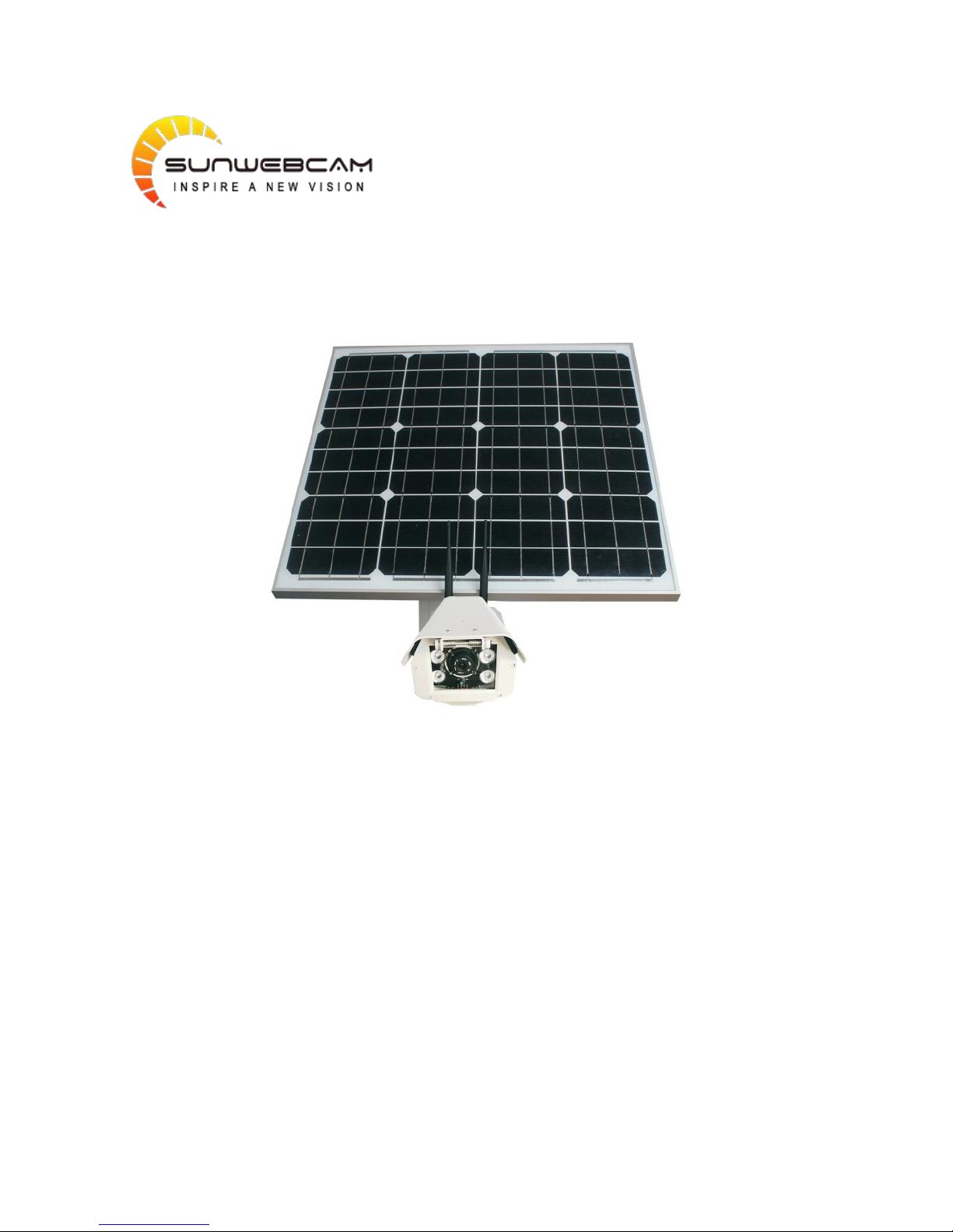
Sunwebcam Solar 4G Camera
User Manual
Page 2

TABLE OF CONTENTS
1. Package List
.................................................................................................................................................................
1
2. The introduction of camera's whole structure
...........................................................................................................
2
2.1 The structure of the Camera
.............................................................................................................................
2
3. Notice
..........................................................................................................................................................................
3
4. User Guide for Smart Phone App
................................................................................................................................
4
4.1. Download and register
.....................................................................................................................................
4
4.1.1. Download the app
................................................................................................................................
4
4.1.2. register
..................................................................................................................................................
4
4.1.3. Add and manage
...................................................................................................................................
4
4.2. Wi-Fi camera
....................................................................................................................................................
4
4.2.1. Connect the Wi-Fi of cameras
..............................................................................................................
4
4.2.2. Local Camera
.........................................................................................................................................
5
4.2.3. Set the camera to connect to the router
..............................................................................................
5
4.2.4. Add camera to account
.........................................................................................................................
6
4.3. 4G camera
........................................................................................................................................................
7
4.3.1. 3G/4G Parameters setting
....................................................................................................................
7
4.4. Ethernet camera
..............................................................................................................................................
8
4.5. List of cameras and Operation
.........................................................................................................................
8
4.5.1. Interface
................................................................................................................................................
8
4.5.2. RTMP push flow Settings
......................................................................................................................
9
4.5.3. Add RF devices
....................................................................................................................................
10
4.5.4. SD / Cloud Record
...............................................................................................................................
10
4.5.5. Locate Camera
....................................................................................................................................
11
5. User Guide for PC Client
............................................................................................................................................
11
5.1. Preparations required before installation
.....................................................................................................
11
5.2. Detailed introductions for installation process
.............................................................................................
11
5.2.1. Installation process preview
...............................................................................................................
11
5.2.2. Detailed introductions for basic installation process
.........................................................................
11
5.3. Installation of RFID accessories (optional)
....................................................................................................
16
5.4. Camera advanced parameter setting
............................................................................................................
16
5.4.1. The parameter settings for 3G, 4G version
........................................................................................
16
5.4.2. Audio and video parameters settings
.................................................................................................
17
5.4.3. Video recording parameters settings
.................................................................................................
18
5.4.4. Motion Zone
.......................................................................................................................................
19
5.4.5. FTP recording (support TI program)
...................................................................................................
19
5.4.6. Cloud Storage Settings
........................................................................................................................
21
5.4.7. Other important settings, including RS485 baud rate and IR lighting control mode
........................
21
5.4.8. System Information
.............................................................................................................................
22
6. Advanced function introduction of 51 See PC clients
..............................................................................................
23
6.1.
Advanced setting
............................................................................................................................................
23
6.2. Browsing cloud video
.....................................................................................................................................
23
6.3. Alarming PUSH Notification and remote SD card video recording linkage
...................................................
25
7. How to set up the product
........................................................................................................................................
25
7.1. Assembly of solar panel
.................................................................................................................................
25
Page 3

TABLE OF CONTENTS
7.2. How to assemble camera
...............................................................................................................................
27
7.3. Mount the solar panel or camera on the pole
..............................................................................................
28
7.4. Mount the solar panel or camera on the wall
...............................................................................................
30
Page 4
1
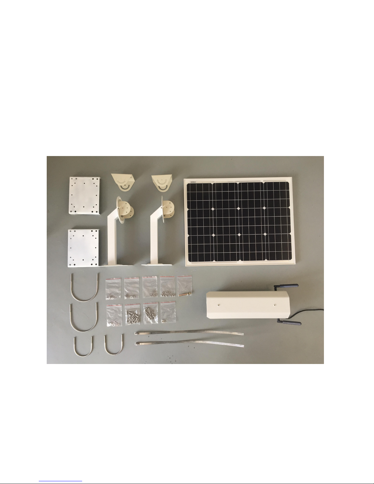
1. Package List
Solar Panel x1
4G Camera x1
Bracket x2
Holder for Pole x2
Holder for angle x2
Stainless Ribbon x6
U Ring (89mm) x2
U Ring (140mm) x2
Accessories (screws, washers, nuts...)
Page 5
2
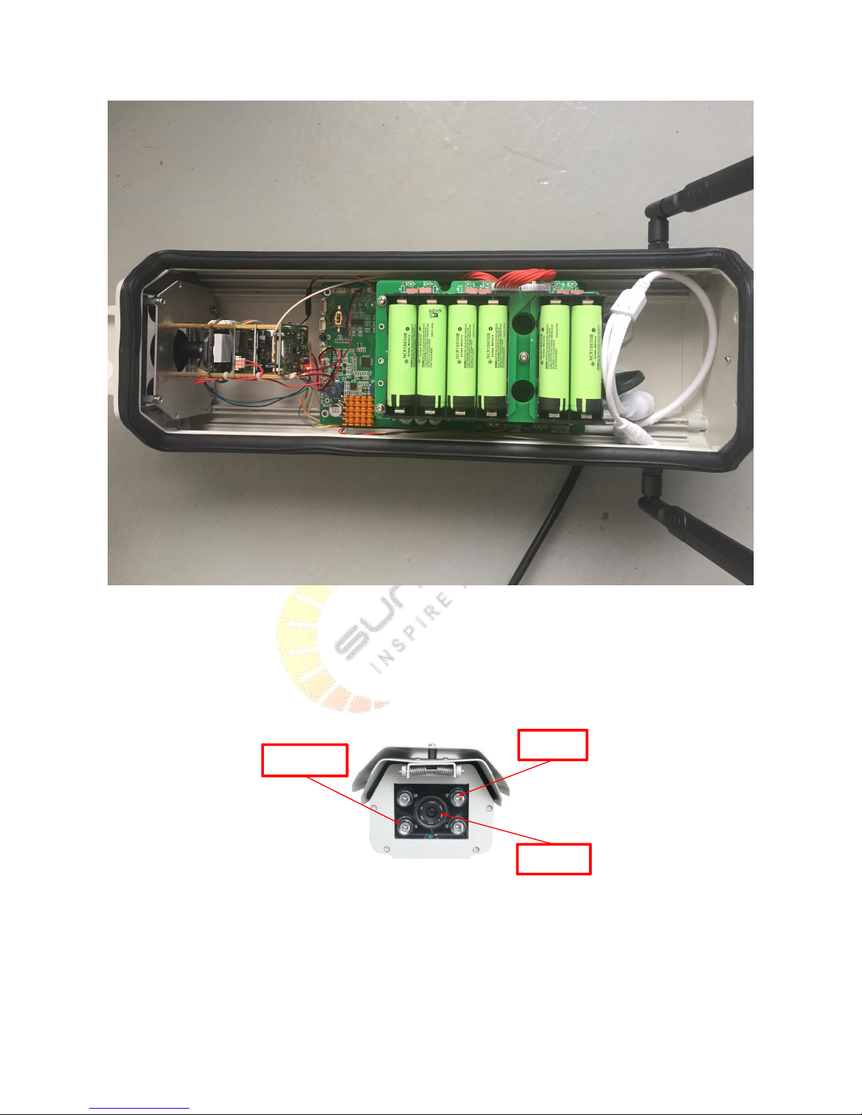
Battery set is built inside. Protective foam is for transportation, please remove it before use.
2. The introduction of camera's whole structure
2.1 The structure of the Camera
Front
cam
IR light
Light
Page 6
3
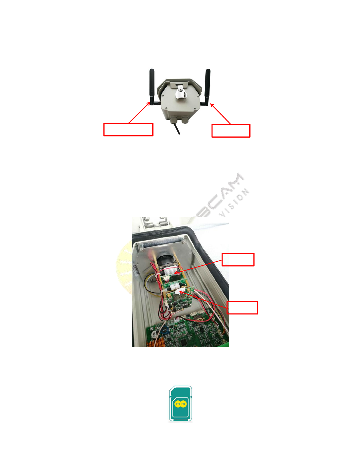
Back
install the antenna as the picture shown, the wifi antenna is on the left, the 4G antenna is on the right, they are
made of different material, please don't replace each other! you mast install them in a right way!
3. Notice
1) The internal structure
The Micro SD Card is inside, the SIM Card is outside.
2) The SIM Card's short side must be upwards, otherwise you will destroy the card slot. Direction is as the picture
shown:
Wi-Fi antenna
4G antenna
Micro SD
SIM Card
Page 7
4
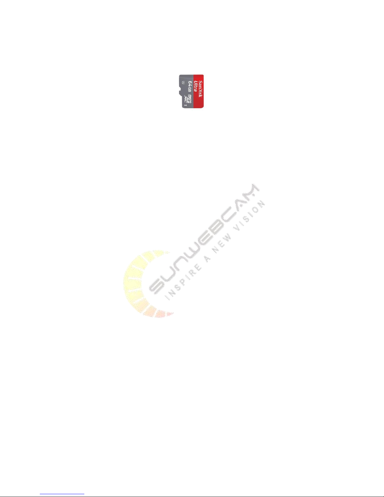
3) The TF card's long side must be upwards, otherwise you will destroy the card slot. Direction is as the picture
shown:
4. User Guide for Smart Phone App
4.1.Download and register
4.1.1. Download the app
You can search 4GCMS on Google Play to download the app!
You can search 4GCMS on App Store to download the app!
4.1.2. register
When you login successfully, you can click the button named ‘register’, you should put your account number and
password in the blank, after that you should click the button named ‘register’, if you register successfully, the app
will show you login!
4.1.3. Add and manage
4GCMS have many ways to add the camera. 4GCMS camera can use the Wi-Fi, 4G and Ethernet to connect the
internet. Here are three ways to add the camera to the account.
4.2.Wi-Fi camera
4.2.1. Connect the Wi-Fi of cameras
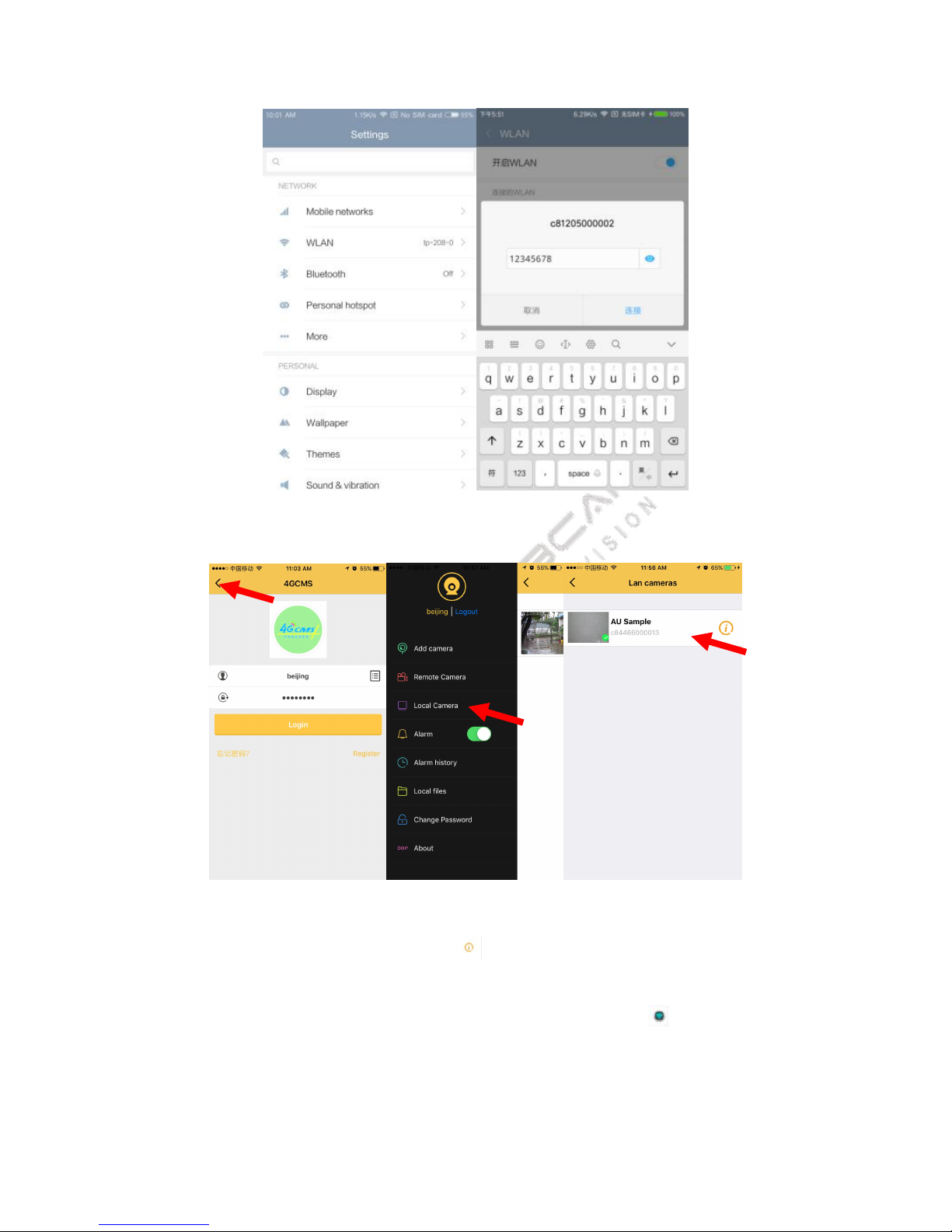
When the camera start, it will launch a Wi-Fi, named by c8 starting. You should connect this Wi-Fi, password is
12345678.
Page 8
5
4.2.2. Local Camera
Open the 4GCMS app, click the local device, you will see the camera after you drop down to refresh the list.
4.2.3. Set the camera to connect to the router
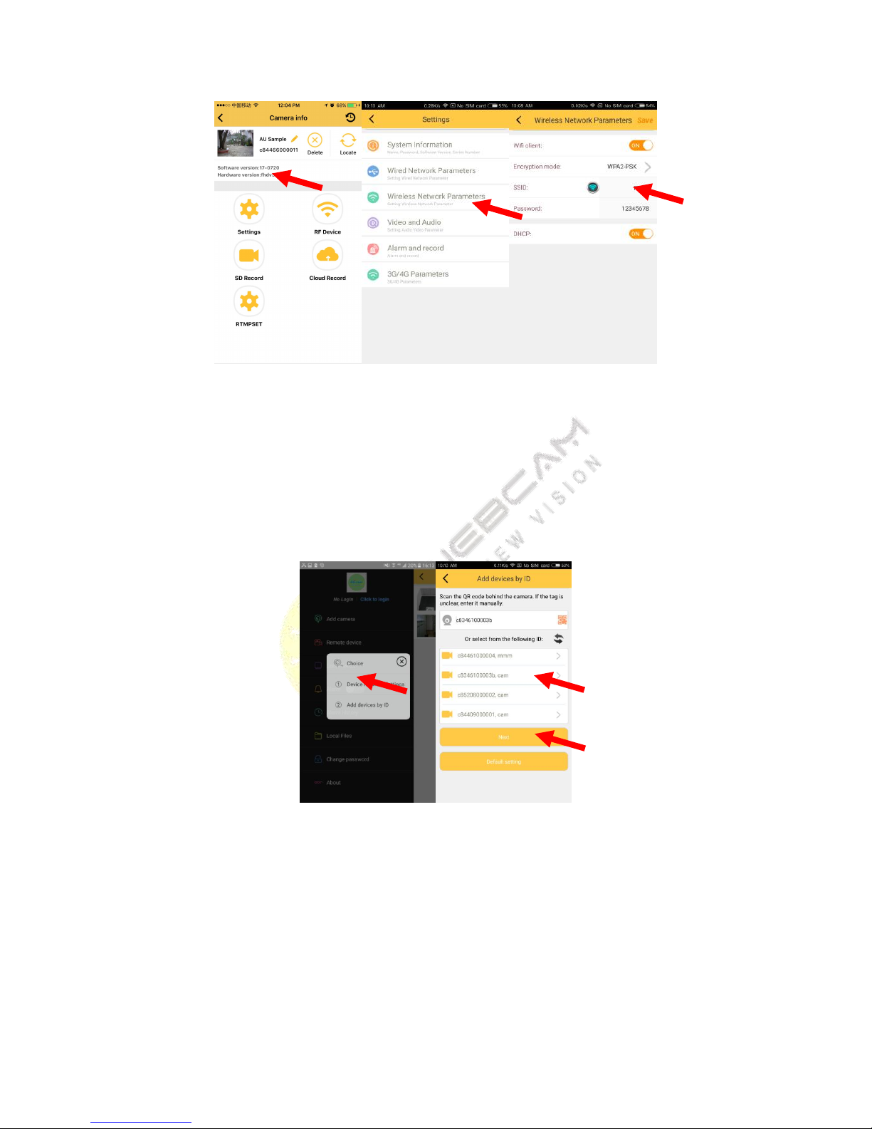
Set the camera connect the Wi-Fi. Click the button , you can see the device information, click the setting
button, choose the wireless Network Parameters, open the Wi-Fi client. SSID is the Wi-Fi name which one you
want to connect, then you should input the password, click the save button(click you will see the Wi-Fi list,
choose the Wi-Fi you want to connect).
Page 9
6
4.2.4. Add camera to account
When you set Wi-Fi successfully, the Wi-Fi of camera will disappear, you should exit the app, open the Wi-Fi
setting interface, connect the Wi-Fi which the camera connect, then you open the app, login to your account,
choose ‘add devices by ID’, select the camera you want to bind, click button next (need about two or three
minutes camera can be seen in the list, please be patient), Do not operate cell phone at this moment, until the
camera add successfully.back to sliding menu, click “Remote device”, refresh the list, you can see the camera you
add.If the camera has not appear in the list, the Wi-Fi setting is failed, you should long press the reset button
which behind the camera,5 second, then you should set again.
Page 10
7
4.3.4G camera
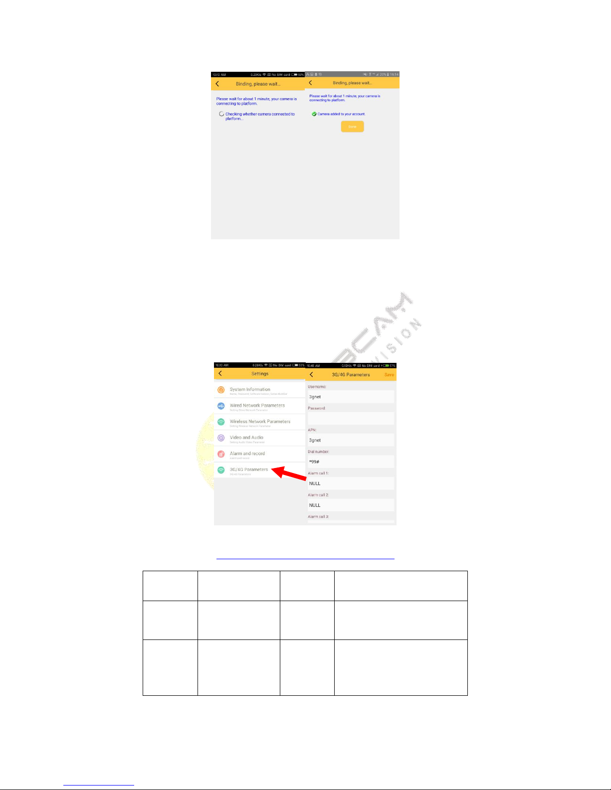
Insert the card correctly, power on the camera,(about 3 minute, please wait), then click ‘add camera’, choose
‘add devices by ID’, input the camera’s ID, click button next, Do not operate cell phone at this moment, until the
camera add successfully. Back to sliding menu, click ‘Remote device’, refresh the list, you can see the camera you
add.
4.3.1. 3G/4G Parameters setting
http://wiki.apnchanger.org/Main_Page
ISP
APN
Dial
Number
account
password
Germany
vodafone
web.vodafone.de
*99#
vodafone
vodafone
Bulgaria
VIVACOM
internet.vivacom.
bg
*99#
VIVACOM
VIVACOM
Page 11
8
4.4.Ethernet camera
Plug in cable, After waiting for the camera in full swing,(about 1 minute, please wait), you should find the
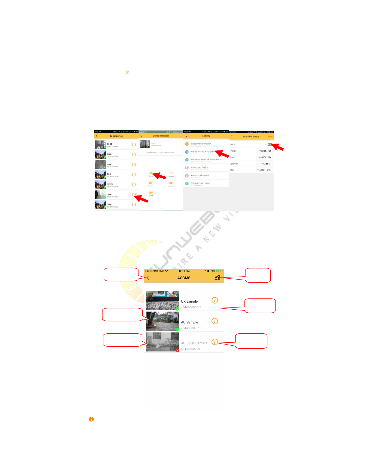
camera in local device list, click , click ‘setting’, click ‘wired Network Parameters’, open the DHCP or input right
IP, finally click save button , then click ‘add camera’, choose ‘add devices by ID’, select the camera you want to bind,
click button next. Do not operate cell phone at this moment, until the camera add successfully. back to sliding
menu, click ‘Remote device’, refresh the list, you can see the camera you add.
If the add failed, the camera can’t connect the internet, you should reset the camera and try again!
4.5.List of cameras and Operation
4.5.1. Interface
When you login successfully ,you will see the management interface of device , as shown in picture
:
click the button , you will enter the device Info interface, you can delete device, modify the name of device,
update the location, search the parameter and settings there. Click the device's thumbnail or device name, you
Sliding menu
Camera online
Camera offline
Device List
Device Info
Map
Page 12
9
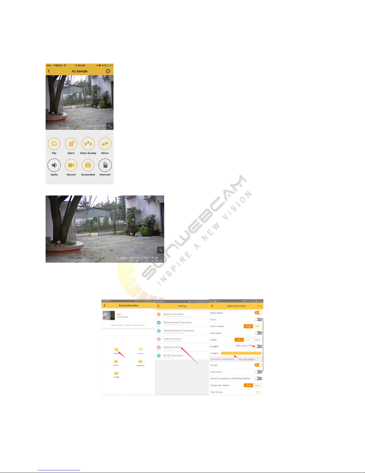
will enter the vision interface, you can view video in real time on the web. Screen direction switches automatically.
Vertical screen mode
Horizontal screen mode
4.5.2. RTMP push flow Settings
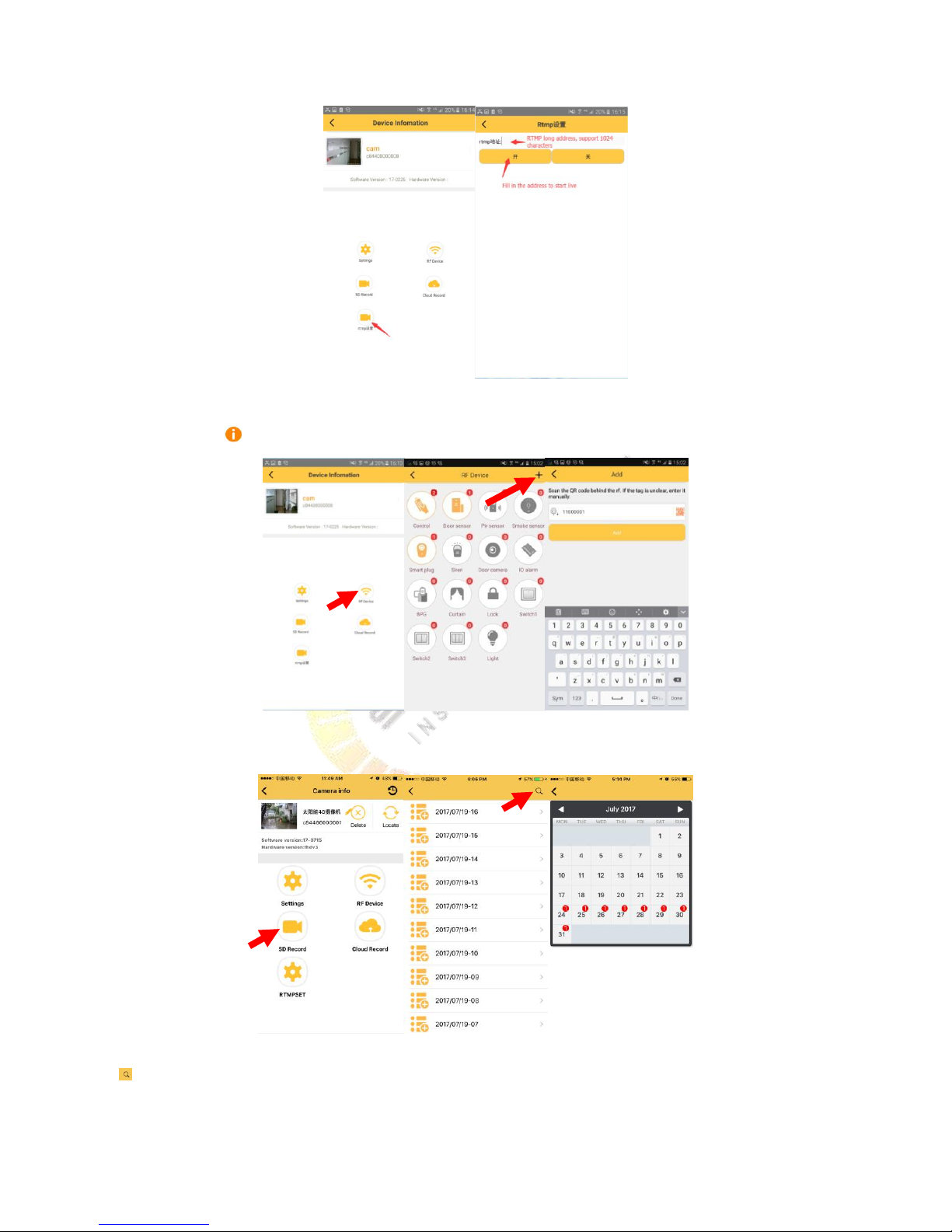
There are two ways, one is through the alarm and video settings, open RTMP, but only supports a short address
within 123 bytes. Following figure
Another way to set up: direct RTMP settings, Following figure.
Page 13
10
4.5.3. Add RF devices
click the button , choose RF Devices, then add the IDs.
4.5.4. SD / Cloud Record
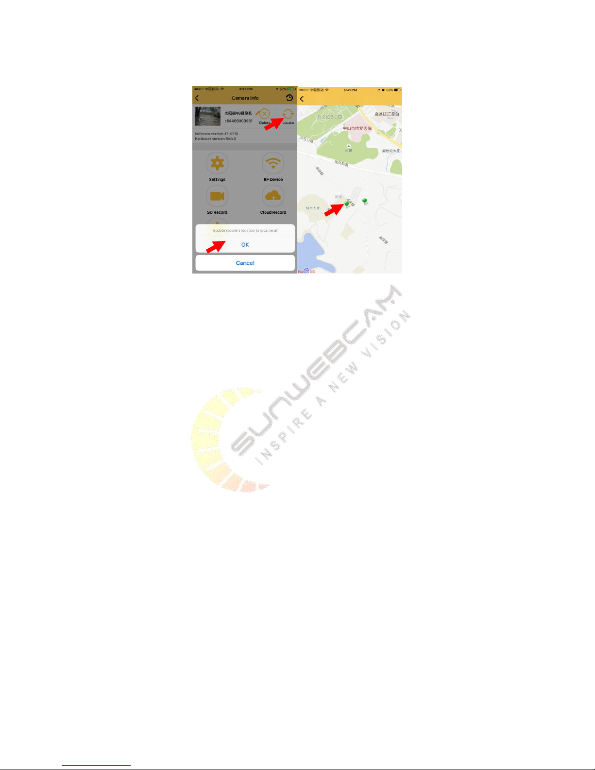
Click ‘SD Record’ or ‘Cloud Record’, you can find alarm record divided in different hours. Click magnifying glass icon
on top right corner, you can select record in different date (red icon means there is record on that date).
Page 14
11
4.5.5. Locate Camera
Click ‘Locate’ on top right corner, you can update mobile’s location to camera. Then you can find cameras on map,
and you can check the camera directly.
5. User Guide for PC Client
5.1.Preparations required before installation
Accessing to the Internet is necessary to use the product, otherwise only PC local videos are available.
You must register for an account to use the product. Note that the computer or mobile phone must have
accessed to the Internet, otherwise the registration will be unsuccessful.
5.2.Detailed introductions for installation process
5.2.1. Installation process preview
1) Connect the CAM and the router with the network cable.
2) Register for an account.
3) Search the camera.
4) Set the network parameters and bind the camera to account.
5) Watch the video.
6) Install the RFID accessories (optional).
5.2.2. Detailed introductions for basic installation process
The detailed introductions of installation process are shown as follows through the example of PC clients.
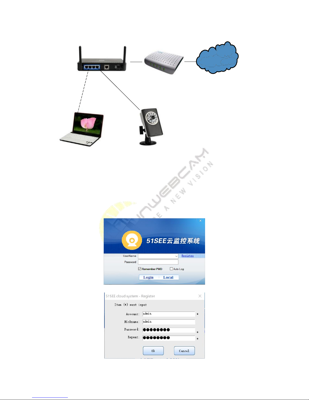
Step 1: Connect the CAM and the router with the network cable
Page 15
12
WIFI Router
Wire
WIFI or wire
PC
ADSL
Internet
CAM
1. Plug in the power adapter.
2. Connect the CAM and the router with the network cable as shown above. Note that PC and the camera need to
be in the same router.
Step 2: Set the 51See CAM process
Run 51SEE cloud system setup.exe. Noting: You must click to provide your permission when the firewall software
prompts the software need the access to the network.
1) Initial interface of 51SEE cloud monitoring system
2) Click the button of ‘Register’.
Page 16
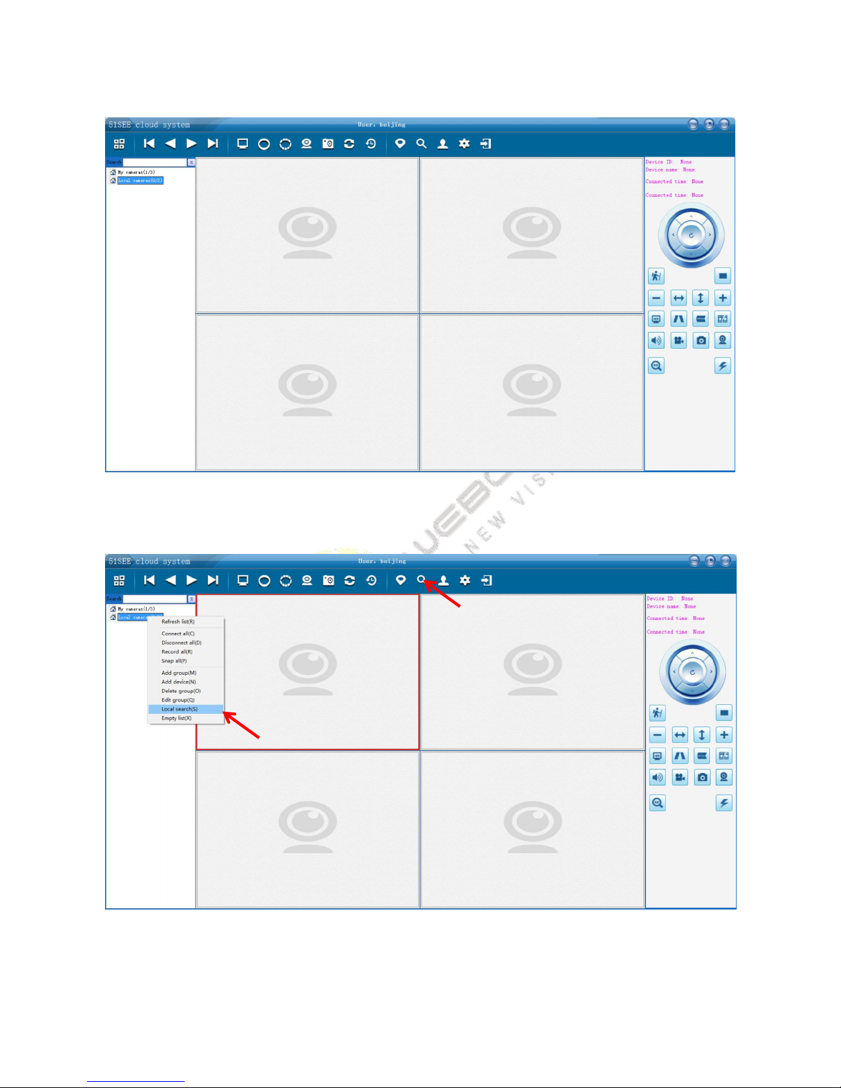
13
3) Fill out the registration information, and click ‘OK’.
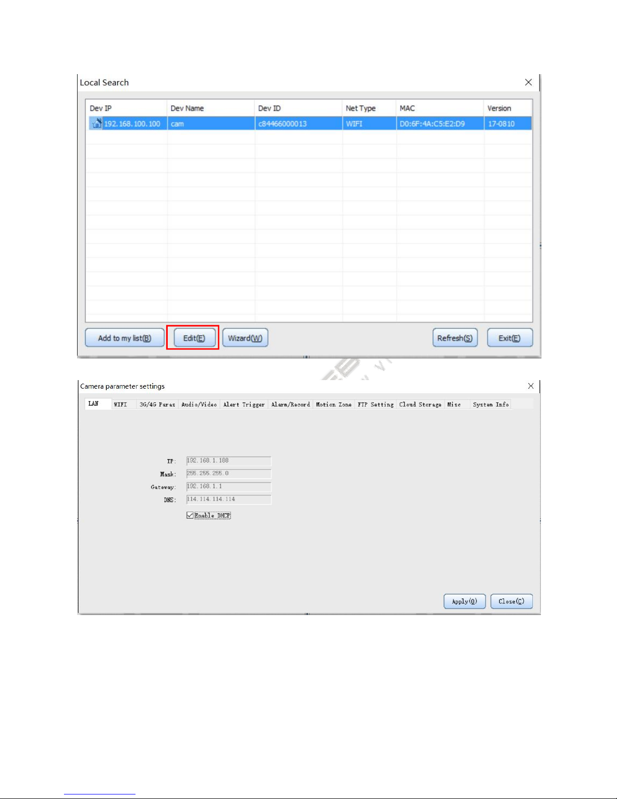
4) After log in, click the ‘local device’ with right mouse button, click ‘local search’ or click the fourth button ‘device
scan’ on the upper right.
5) After searching the camera, double click it or click the ‘Edit’ button.
Page 17
14
6) Set the IP address and click ‘apply’
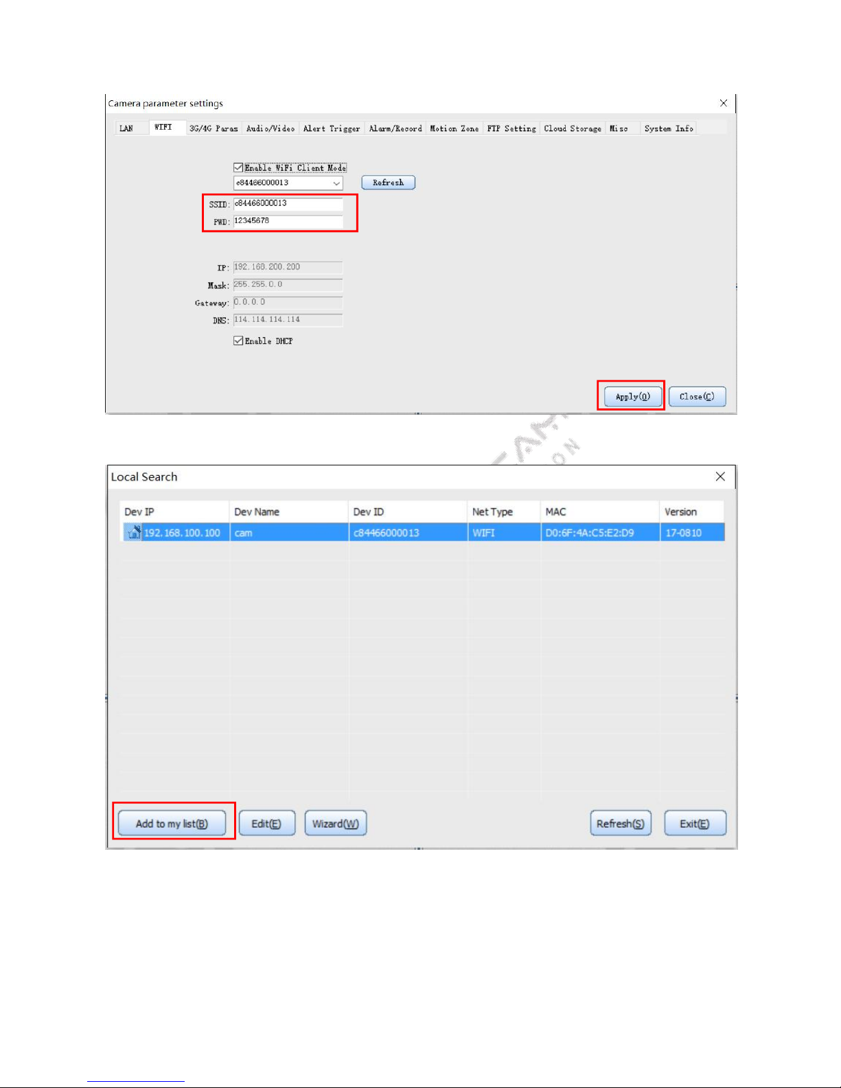
Note: The parameter settings of Wi-Fi version
Select Wi-Fi items in the settings interface, input the SSID and password, and then click ‘apply’.
If you want to use WPS to set Wi-Fi, press and hold the Reset button for more than 4 seconds, release within 10
seconds, press the router's WPS button after the camera system indicator light flashing and the camera will
automatically connect to the router within about 3 to 5 minutes.
Page 18
15
Note: If the camera fails to bind, please restore factory settings for resetting.
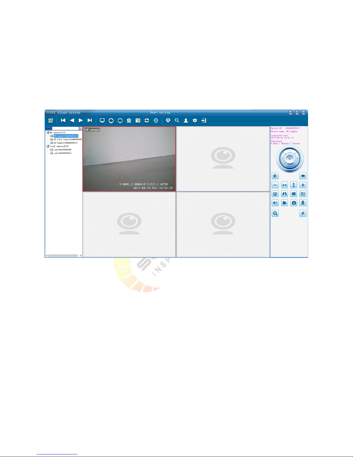
Step 3: Watch the video
Once the installation process is completed, the user can watch videos through PC or mobile phone.
Page 19
16
You can watch video whenever and wherever with a computer or mobile phone as long as you log in the account
through the clients.
For the PC client, the function is more powerful. You should pay attention to the following two points
1. Local device can be watched only when CAM and computer are in the same LAN, and high-definition video are
also available to watch.
2. Remote device can be watched wherever.
Above is the installation instructions through the example of PC client. Installation settings can also be conducted
for iPhone and Android client.
5.3.Installation of RFID accessories (optional)
1) The camera can accept any RFID accessories installation by the code. The code will be invalid after half an hour.
2) After the code matching, please conduct RFID settings through PC client to change the name of the RFID so that
you will know which alarms when the alarms occur. Please refer to Section 4.8 ‘RFID Accessory Settings’.
3) When the RFID codes successfully match, the camera system indicator will quickly flash for 4 seconds.
4) The SOS buttons of remote control in the RFID accessories have the function of highest level. The fortification
will automatically start after press, and it will trigger the alarm.
5) For 3G, 4G equipment with RFID, you can set the phone number for alarm.
5.4.Camera advanced parameter setting
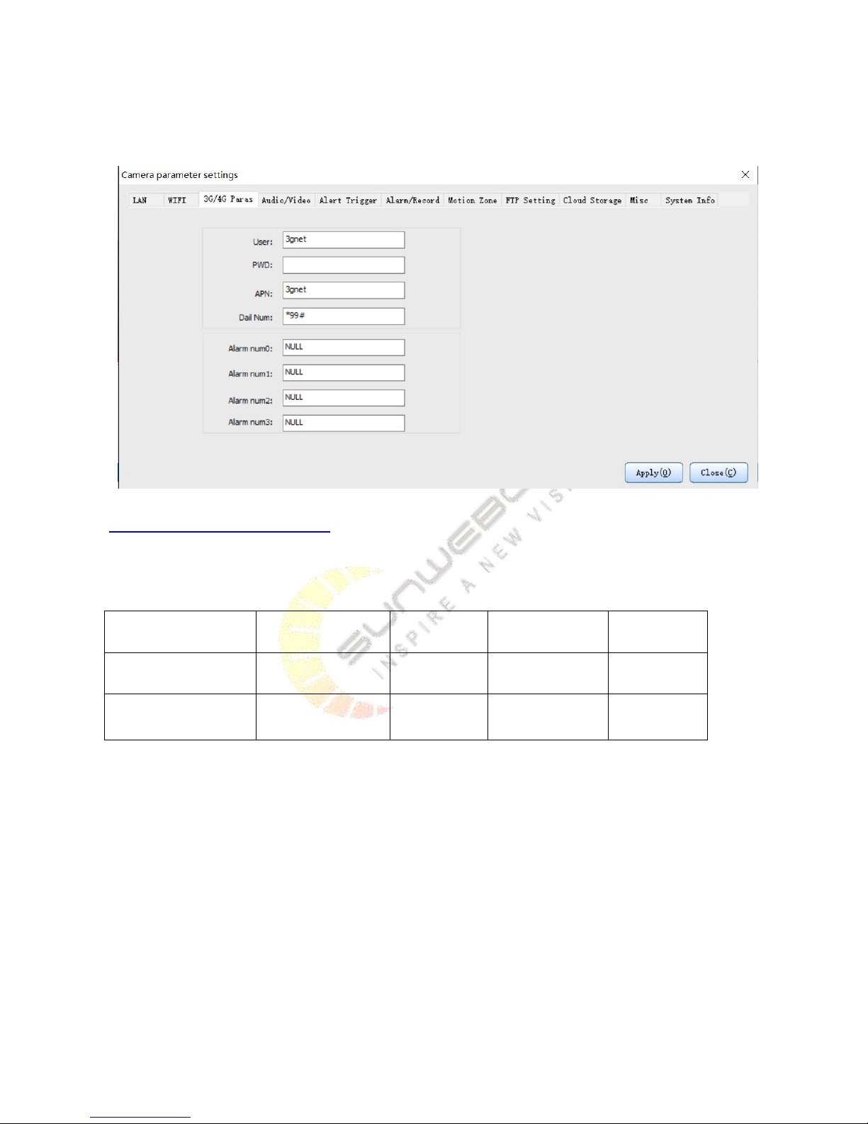
5.4.1. The parameter settings for 3G, 4G version
Page 20
17
In the setting interface, 3G options will automatically appear for the IP camera of 3G, 4G version. Input the
operator's dialing parameters, and click on the application to adapt local operators.
You can refer to the following link for foreign operators:
http://wiki.apnchanger.org/Main_Page The default dialing number is mostly * 99 #. You need to specifically check
the local operators. The common operators are as follows:
Note: The 3G, 4G machines support alarm dialing function, but they must be used in conjunction with the wireless
alarm.
5.4.2. Audio and video parameters settings
ISP
APN
Dial number
User
Password
German vodafone
web.vodafone.de
*99#
vodafone
vodafone
Bulgaria VIVACOM
internet.vivacom.bg
*99#
VIVACOM
VIVACOM
Page 21
18
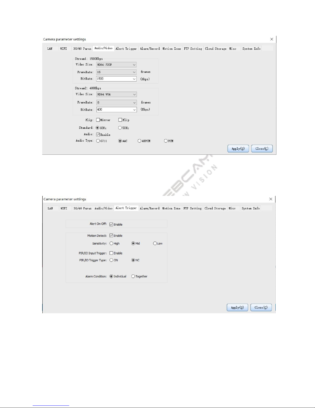
If you think the image is not clear enough, you can set the bit rate higher.
For 51See clients, only AAC Audio Type format is supported.
5.4.3. Video recording parameters settings
Above figure is to set the alarm trigger conditions. It can be achieved through motion detection or PIR or IO trigger.
One key fortification is the main switch, and all alarm settings will be invalid once the parameter is canceled.
For the device with PIR, PIR/IO Input Trigger should be Enable.
If you want less false alarm, you should choose Alarm Condition ‘Together’.
Page 22
19
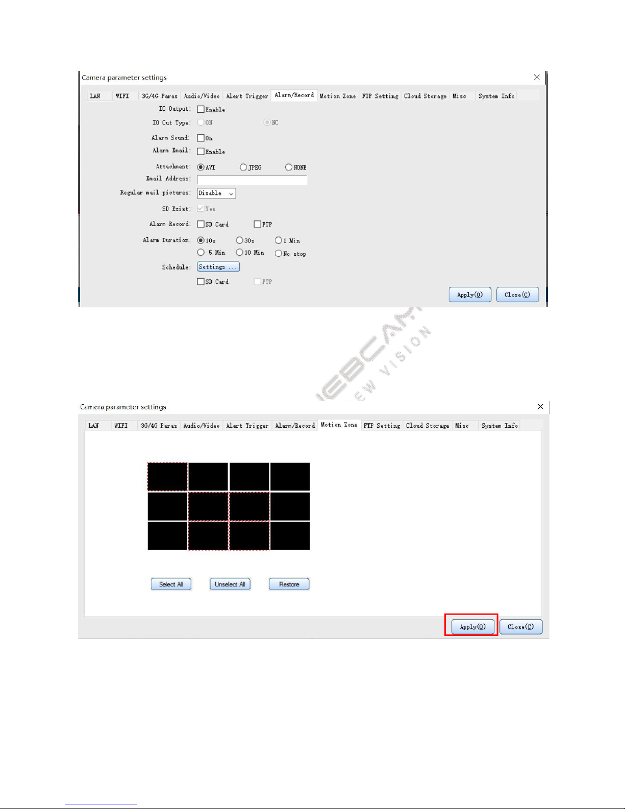
Above figure is the action after setting the alarm. Note:
For users who need to send video at regular intervals, fill in the email address on the above chart and set the time
interval of timed photography to send email.
5.4.4. Motion Zone
Select the zone that you want to detect, click ‘Apply’.
5.4.5. FTP recording (support TI program)
Page 23
20
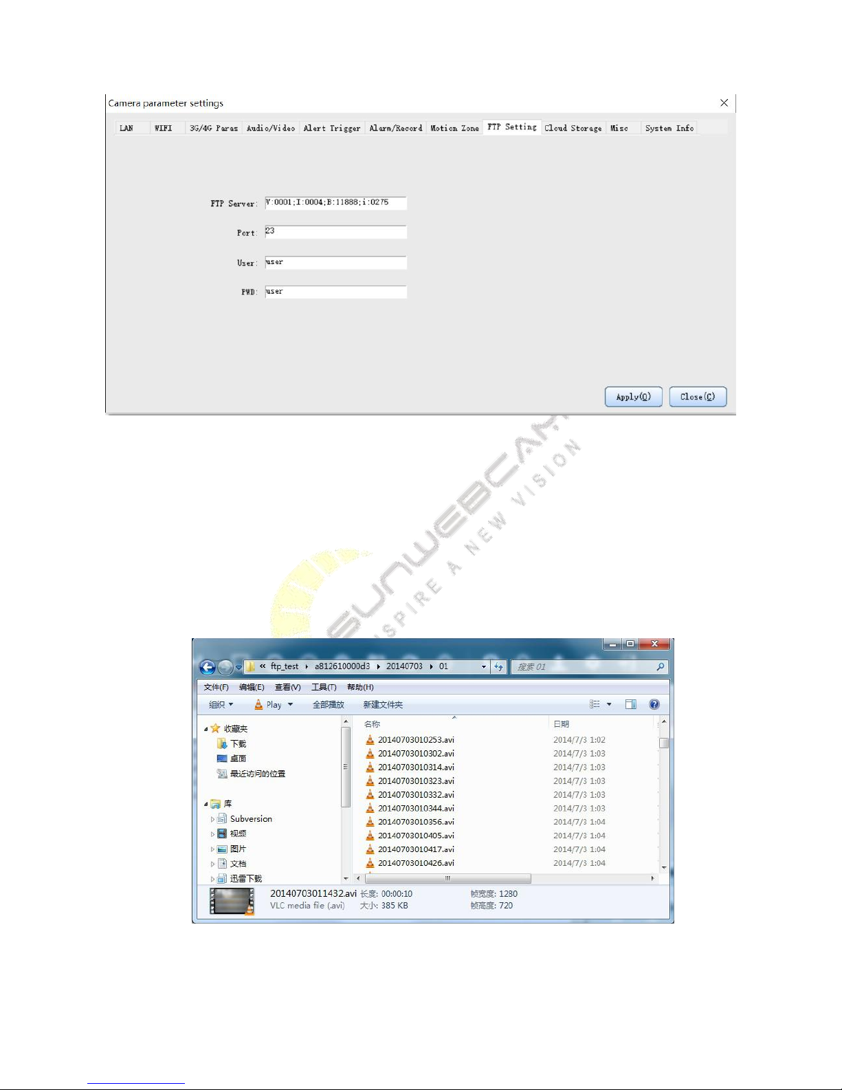
Note: FTP only works when there is no SD card.
Fill in the FTP parameters in the above dialog box, and select the alarm FTP or scheduled video recording FTP in
the alarm recording settings, and the videos will be automatically recorded to the ftp server. In order to make the
application simpler, we don’t need the users to set ftp folder, and the camera will save the videos through the
following rules:
Ftp root directory \ camera ID \ yymmdd \ hh \ yymmddhhmmss.avi. The data will be stored through such rules,
which are shown as follows:
Page 24
21
5.4.6. Cloud Storage Settings
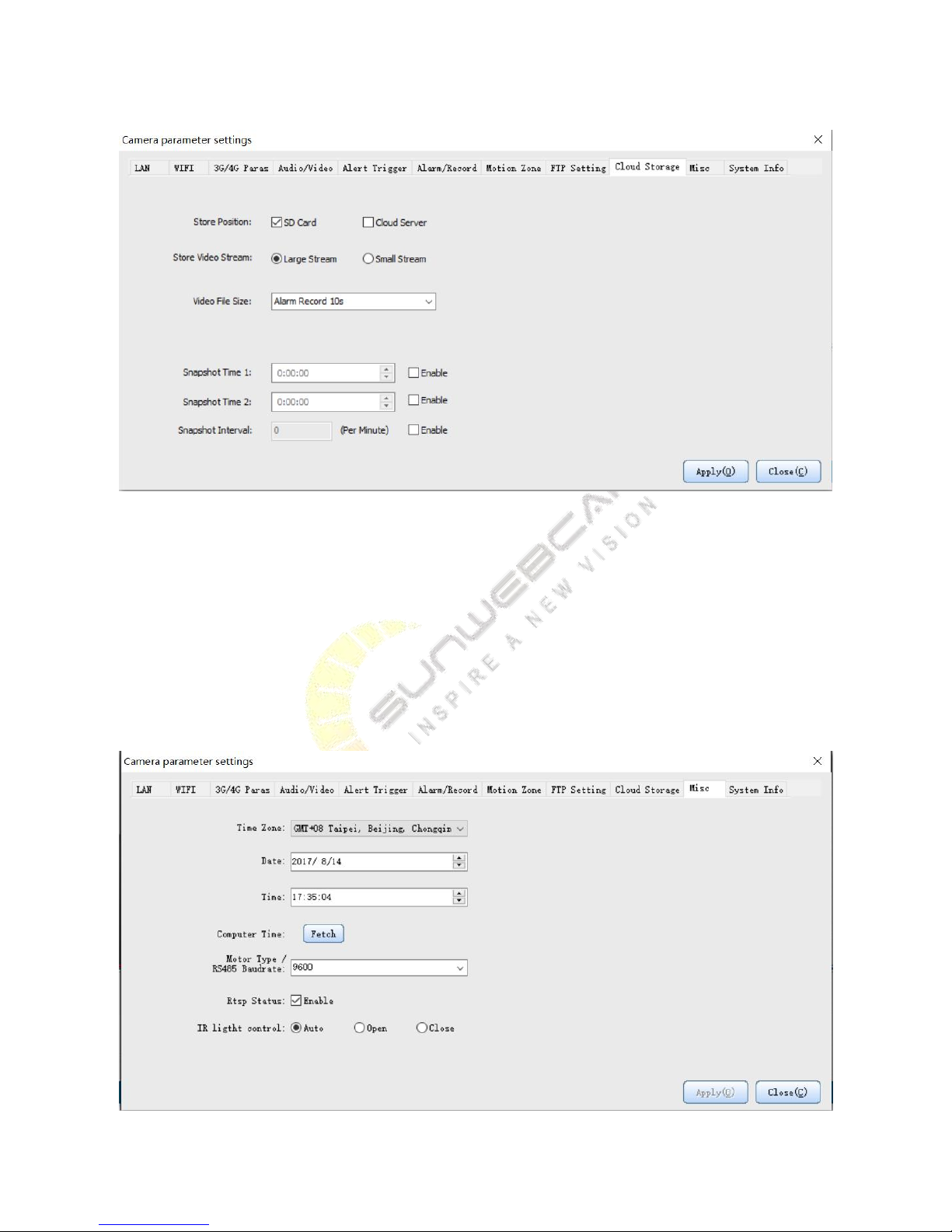
Description of cloud storage settings:
1) Select the SD card video recording, and then the SD card will be the only place for recording. If there is no SD
card, storage space about 40MB inside the camera can be used for cycle video.
2) Cloud storage server provides each user with 500MB storage space in default, which will be automatically
replaced when the recording space is full.
3) For video file size, you can choose large or small bit stream.
4) You can determine how many seconds to save for each trigger.
5) The video format is MP4.
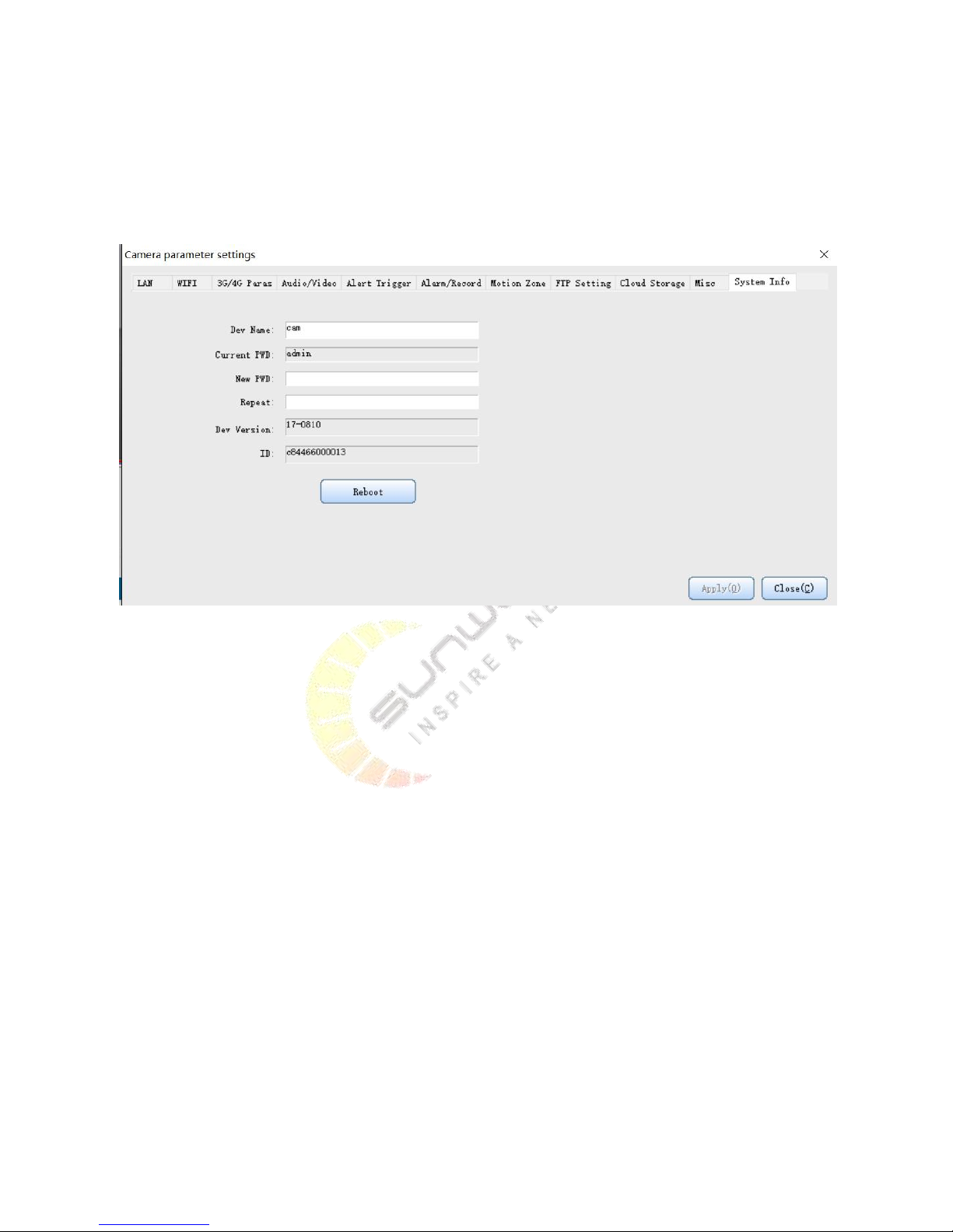
5.4.7. Other important settings, including RS485 baud rate and IR lighting control mode
Page 25
22
1) RS485 baud rate setting item
RS485 baud rate setting item is significant to control the external machine pan-tilt through RS485 interface. The
ball machine will not be able to operate if the baud rate is not right, so do not set it up casually.
5.4.8. System Information
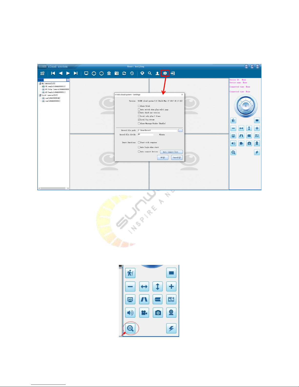
You can modify the camera password, restore factory settings and restart the camera here. Note: The user name
of the camera is admin. The default password is admin. The user name is not allowed to modify, and only camera
password is allowed for modification, which should be less than 16 characters.
Page 26
23
6. Advanced function introduction of 51 See PC clients
6.1. Advanced setting
Alarm blink. The window will automatically blink when an alarm occurs in the screen.
Local only play I frame. If the user’s computer configuration is relatively low, only I frame for local play will
greatly reduce the CPU occupancy rate, and can record video smoothly in the local disk.
Local big stream. High-definition video of big stream can be chosen for LAN viewing. Small bit stream is
suitable for computers with relatively poor configuration.
Alarm Message Window. The window will be automatically opened when alarm message appears.
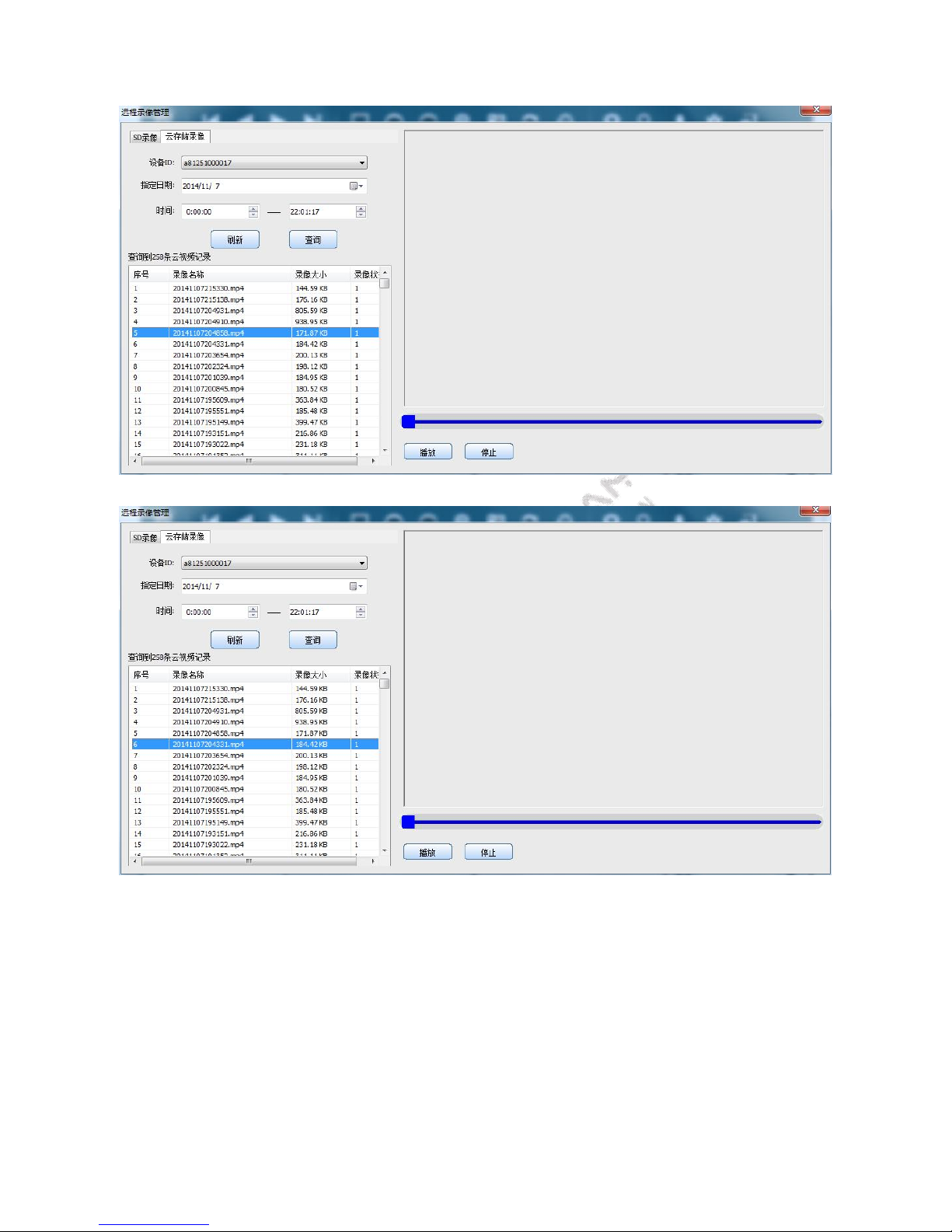
6.2.Browsing cloud video
Page 27
24
Page 28

25
6.3.Alarming PUSH Notification and remote SD card video recording linkage
In the setting item, conduct setting so that the alarm window automatically pop up or the alarm window will
automatically pop up when the mouse is moved to the bottom. Double click on one of them can link to the alarm
history browsing interface.
7. How to set up the product
7.1.Assembly of solar panel
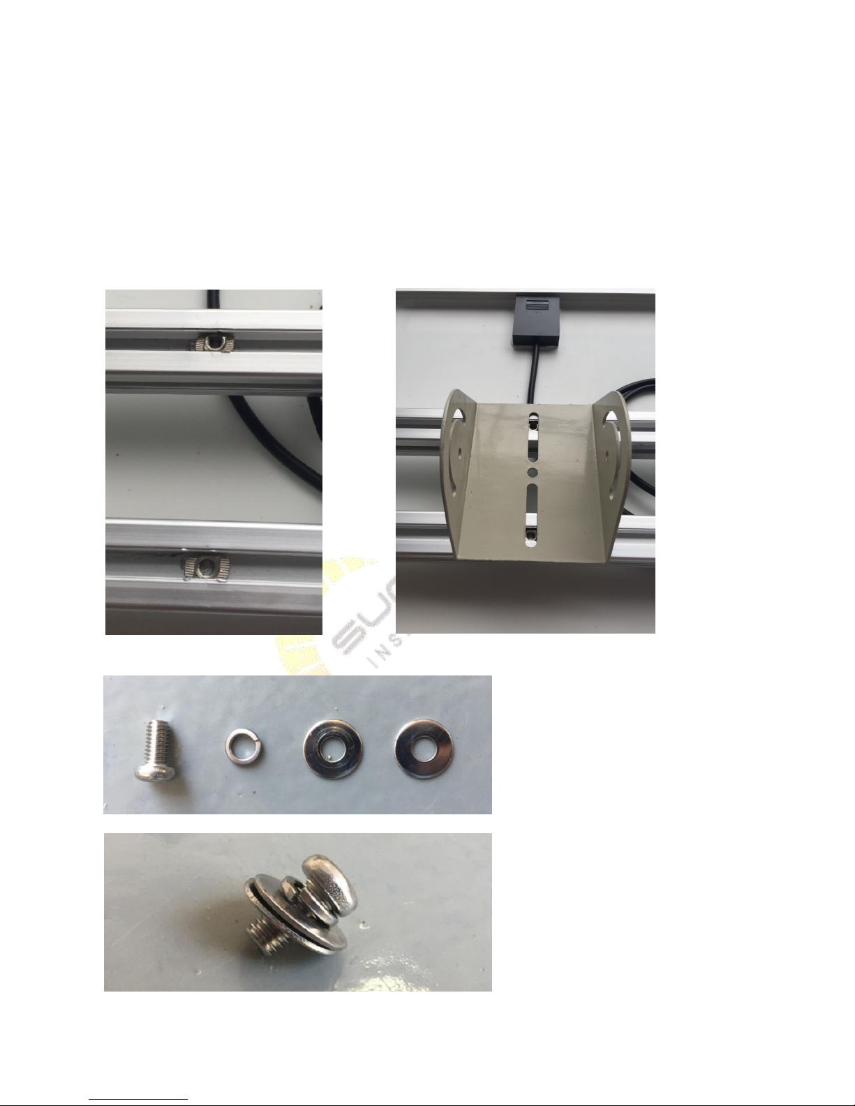
Step 1. Assemble 'Holder for Angle' on Solar Panel. You can find below parts in our package.
Double click to check video
Page 29
26
Solar Panel x1
Holder for Angle x1
M6 Cross Screw x2
M6 Pad Washer x4
M6 Spring Washer x2
Square Nut x2
Put the Square Nut into the slot of Solar Panel ( the Square Nuts should be put at the middle of the Solar Panel).
Then put the 'Holder of Angle' on the Solar Panel, aligning with the Square Nuts.
Put the Spring Washer and 2pcs Pad Washer into the M6 Cross Screw, just like the second photo above.
Page 30
27
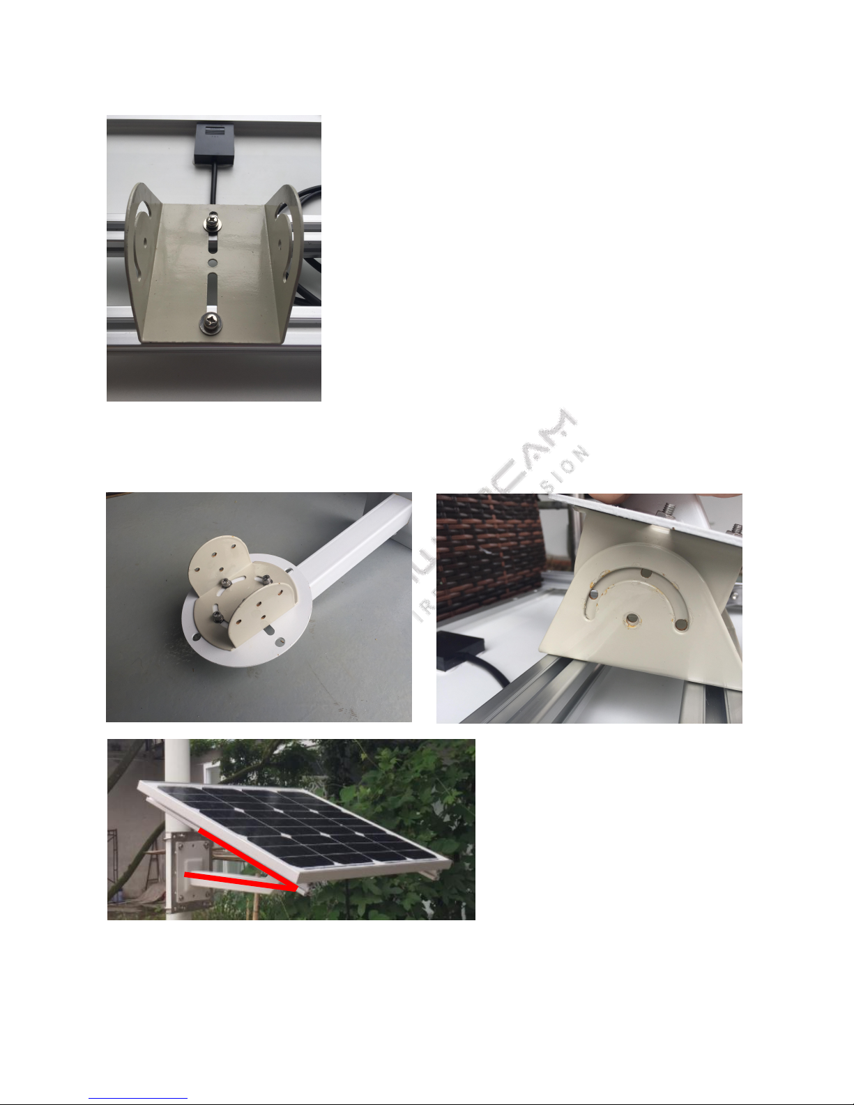
Lock screws to make the holder unmovable.
Step 2. Assemble Solar Panel with Bracket
Align the arc slot of Solar Panel with 4 holes of Bracket. You can adjust the angle before screw ( suggest the angle
less than 45°). Put Spring Washer and Pad Washer into M6 Screw, then lock screw.
7.2.How to assemble camera
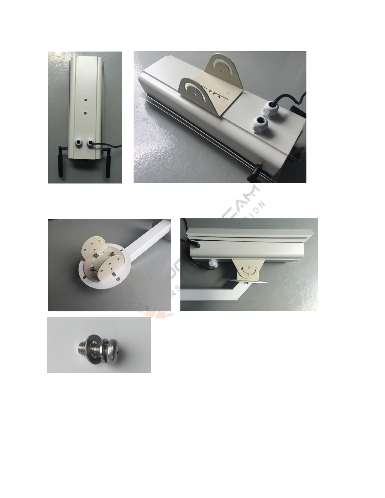
Step 1. Assemble Holder for Angle on Camera
Page 31
28
Unscrew the screws on the bottom of camera, then lock the Holder for Angle on it.
Step 2. Assemble Bracket on Camera
Align the arc slot of Camera with 4 holes of Bracket. You can adjust the angle before screw. Put Spring Washer and
Pad Washer into M6 Screw, then lock screw.
7.3.Mount the solar panel or camera on the pole
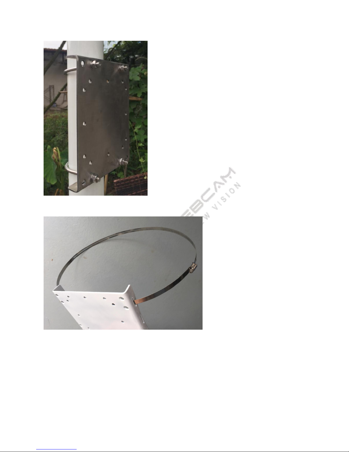
There are two ways to mount the holder on the pole ( use U Ring or stainless Ribbon).
For the Pole diameterφ60mm~140mm,you can use U Ring, locked by nuts like photo below.
Page 32
29
For the pole with bigger diameter, you should turn the holder at 90°. We design 3 slots for ribbon use.
No matter using U Ring or Stainless Ribbon, we have designed holes with thread for Bracket. Put the Spring
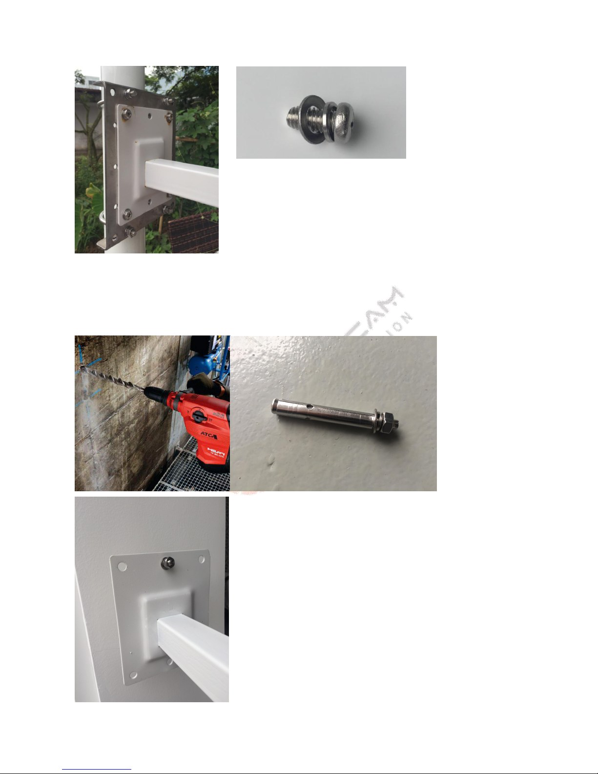
Washer and Pad Washer into the M8 Cross Screw. Align the holes on Bracket with the holes on holder, then lock
the screws.
Page 33
30
7.4.Mount the solar panel or camera on the wall
Drill 6 holes on the wall, then put the blasting screws inside. Align the bracket holes with blasting screws, and lock
it with the nuts.
 Loading...