

LCR METE
R
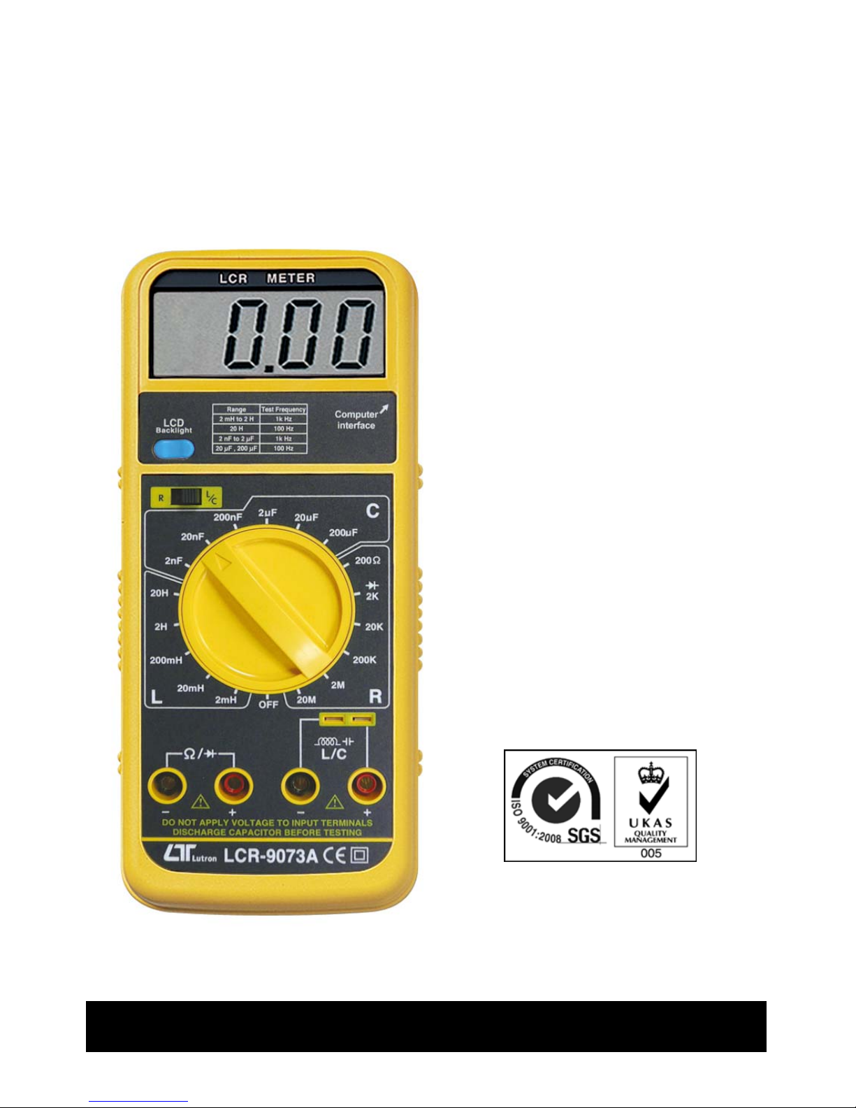
Model : LCR-9073A
Y
our purchase of this LCR
METER marks a step
forward for you into the
field of precision
measurement. Although
this LCR METER is a
complex and delicate
instrument, its durable
structure will allow many
years of use if proper
operating techniques are
developed. Please read
the following instructions
carefully and always keep
this manual within easy
reach.
OPERATION MANUAL

TABLE OF CONTENTS
1. FEATURES................................................................ 1
2. SPECIFICATIONS...................................................... 1
2-1 General Specifications..........................................1
2-2 Electrical specifications........................................
.
3
3. FRONT PANEL DESCRIPTION....................................
.
6
3-1 Display .............................................................. 6
3-2 LCD backli
g
ht ON/OFF button...............................6
3-3 LC/R select switch .............................................. 6
3-4 Function rotary switch/Power switch..................... 6
3-5 L/C Measuring terminal 1.................................. 6
3-6 L/C Measuring terminal 2 .................................. 6
3-7 Resistance/Diode Measurin
g
terminal ...................6
3-8 RS-232 Output Terminal......................................
.
6
3-9 Stand ................................................................
.
6
3-10 Battery cover Screw ..........................................6
3-11 Battery Compartment/Cover .............................. 6
4. INDUCTANCE (L) MEASUREMENT PROCEDURE ..........7
5. CAPACITANCE (C) MEASUREMENT PROCEDURE ........ 7
6. RESISTANCE (R) MEASUREMENT PROCEDURE ..........
.
9
7. DIODE MEASURING PROCEDURE...............................9
8. MAINTENANCE ........................................................
.
11
9. RS232 COMPUTER INTERFACE..................................
.
11
10. BATTERY REPLACEMENT ........................................ 13
1. FEATURES
* Professional LCR meter, used the LSI-circuit and
exclusive microprocessor circuit, high reliability and
High measuring accuracy.
* Wide ranger measurement for Inductance, Capacitance
and Resistance measurement.
* Test frequency : 100 Hz, 1 KHz.
* Input overload protection
* Rotary switch function selector.
* RS232/USB Computer interface.
*Diode test.
* Large LCD display with backlight.
* Built-in low battery indicator
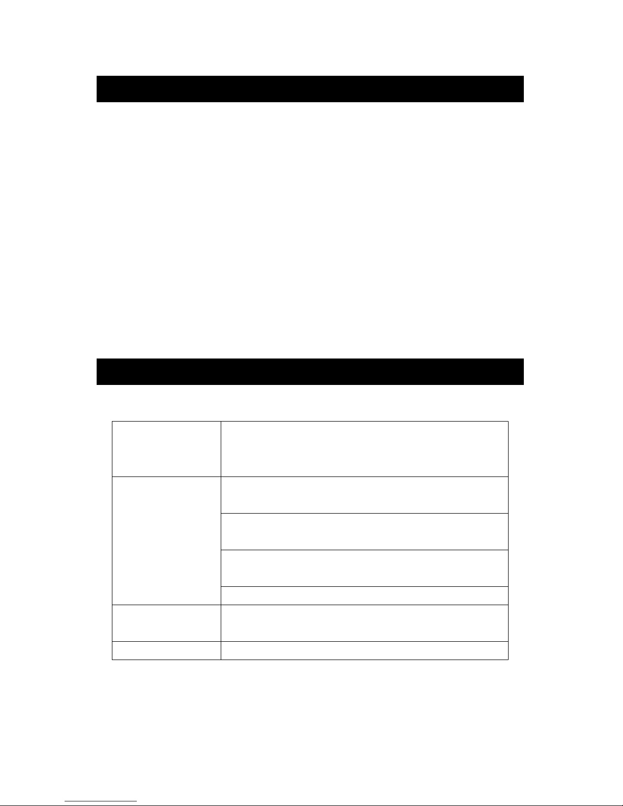
2. SPECIFICATIONS
2-1 General Specifications
Display 67 mm x 27 mm large LCD display.
17 mm x 9 mm, digit size.
* With LCD backlight ON/OFF control.
Measurement
Inductance ( L ) :
5 ranges : 2 mH to 20 H.
Capacitance ( C ) :
6 ranges : 2 nF to 200 uF.
Resistance ( R ) :
6 ranges : 200 ohm to 20 Mega ohm.
Diode test
Circuit Custom one-chip of microprocessor LSI
circuit
Sampling Time Approx. 0.4 second.
1

Data Output RS 232/USB PC computer interface.
* Connect the optional RS232 cable
UPCB-02 will get the RS232 plug.
* Connect the optional USB cable
USB-01 will get the USB plug.
Over Input Show " 1 " indicator.
Indication
Operating 0 to 50 ( 32 to 122 ).℃℃℉ ℉
Temperature
Operating Less than 80% RH.
Humidity
Power Supply Alkaline or heavy duty type DC 9V
battery, 006P, MN1604 (PP3) or
equivalent.
Power Approx. 12 mA.
Consumption
Weight 314 g/0.69 lb.
Dimension 204 x 90 x 36 mm
( 8.0 x 3.5 x 1.4 inch ).
Accessories Instruction manual............... 1 PC.
Included
T
est alligator clips................ 1 Pair.
Optional * Data Acquisition software,
Accessories SW-801-WIN
* USB cable, USB-01
* RS232 cable, UPCB-02
2
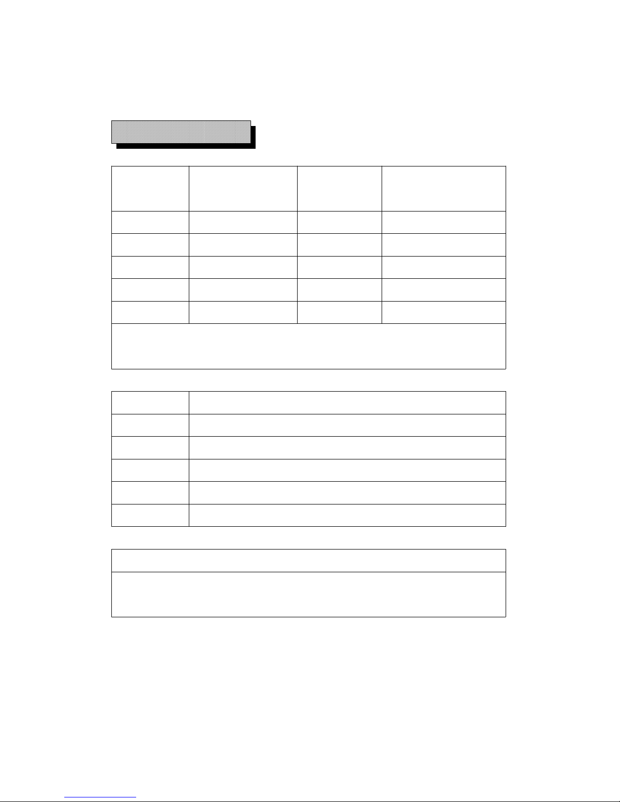
2-2 Electrical specifications ( 23 ± 5 )℃
L ( Inductance )
Range Resolution Test Accuracy
Frequency
2 mH 1 uH 1 kHz ± ( 2 %+2d )
20 mH 10 uH 1 kHz ± ( 2 %+2d )
200 mH 100 uH 1 kHz ± ( 2 %+2d )
2 H 1 mH 1 kHz ± ( 5 %+2d )
20 H 10 mH 100 Hz ± ( 5 %+2d )
uH = micro Henry ( 10^-6 H )
mH = mili Henry ( 10^-3 H )
Range Current through Inductance under test
2 mH 150 u A
20 mH 150 u A
200 mH 150 u A
2 H 150 u A
20 H 15 u A
Overload Rating
AC 10V ( 50 Hz/60 Hz ) max, or DC 10V max.,
less than 30 second.
3

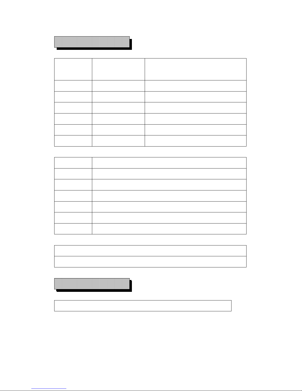
C ( Capacitance )
Range Resolution Test Accuracy
Frequency
2 nF 1 pF 1 kHz ± ( 2 %+2d )
20 nF 10 pF 1 kHz ± ( 2 %+2d )
200 nF 100 pF 1 kHz ± ( 2 %+2d )
2 uF 0.001 uF 1 kHz ± ( 2 %+2d )
20 uF 0.01 uF 100 Hz ± ( 2 %+2d )
200 uF 0.1 uF 100 Hz ± ( 2 %+2d )
pF = pico Farad ( 10^-12 F )
nF= nano Farad (10^-9 F )
uF= micro Farad ( 10^-6 F )
Range Voltage across Capacitance under test
2n F 150 mV
20 nF 150 mV
200 nF 150 mV
2 uF 150 mV
20 uF 150 mV
200 uF 15 mV
Overload Rating
Charged capacitor 100 uF/ 50 V Max.
4
R ( Resistance )
Range Resolution Accuracy
200 Ω 0.1Ω ± ( 1 % + 2d )
2 kΩ 1 Ω ± ( 1 % + 2d )
20 kΩ 10 Ω ± ( 1 % + 2d )
200 kΩ 100 Ω ± ( 1 % + 2d )
2 MΩ 1 kΩ ± ( 1 % + 2d )
20 MΩ 10 kΩ ± ( 2 % + 2d )
Range Open circuit Voltage
200 Ω 2.4 V
2 kΩ 2.4 V
20 kΩ Approx. DC 250 m V
200 kΩ Approx. DC 250 m V
2 MΩ Approx. DC 250 m V
20 MΩ Approx. DC 250 m V
Overload Rating
AC / DC 500V at 20 seconds Max.
Diode test
Short/non conductance, good/defect test
5
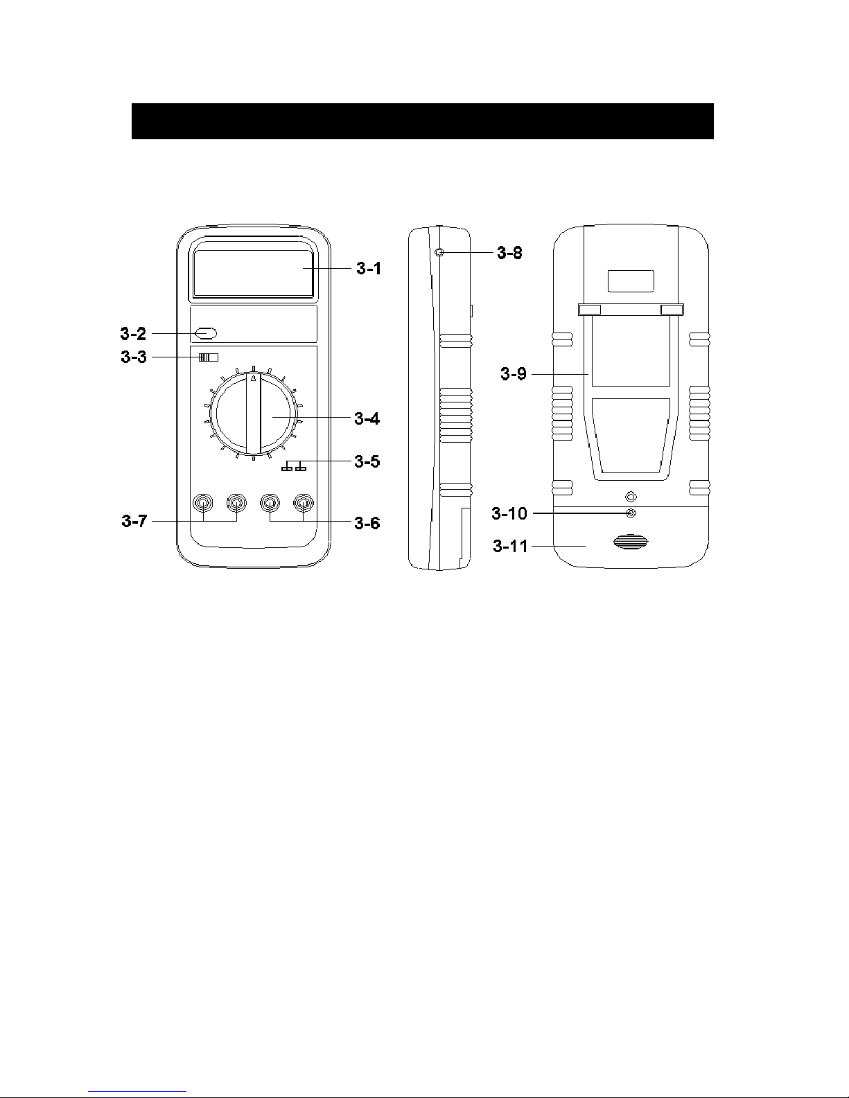
3. FRONT PANEL DESCRIPTION
Fig. 1
3-1 Display
3-2 LCD backlight ON/OFF button
3-3 LC/R select switch
3-4 Function rotary switch/Power switch
3-5 L/C Measuring terminal 1
3-6 L/C Measuring terminal 2
3-7 Resistance/Diode Measuring terminal
3-8 RS-232 Output Terminal
3-9 Stand
3-10 Battery cover Screw
3-11 Battery Compartment/Cove
6

4. INDUCTANCE (L) MEASUREMENT
PROCEDURE
1)Slide the " LC/R select switch " ( 3-3, Fig. 1 ) to the " LC "
position.
2)Rotate the function switch for the maximum expected
inductance range.
3) Fully discharge any charged inductors.
4)Insert the tested inductor into socket " L/C Measuring
input terminal 1 " ( 3-5, Fig. 1 ). Alternatively, connect
the inductor to " L/C Measuring input terminal 2 " ( 3-6,
Fig. 1 ). via using the measuring alligators supplied .
Note :
a. If the inductance value is unmarked start with the
highest range and keep decreasing until a suitable
reading is obtained.
b. Measurement of very low inductance should be
performed using extremely short leads in order to
avoid introducing any stray inductance.
c. This instruments is not intended for determining the
" Q " factor for the inductor. Misleading readings may
be obtained if the measurement of the inductance of
a resistor is attempted.
5. CAPACITANCE (C) MEASUREMENT
PROCEDURE
1)Slide the " LC/R select switch " ( 3-3, Fig. 1 ) to the " LC "
position.
7

2)Rotate the function switch for the maximum expected
capacitance range.
3) Fully discharge any charged capacitors.
4)Observe polarity when connecting polarized capacitors.
5)Insert the tested capacitor into socket " L/C Measuring
input terminal 1 " ( 3-5, Fig. 1 ). Alternatively, connect
the capacitor to " L/C Measuring input terminal 2 " ( 3-6,
Fig. 1 ) via using the measuring alligators supplied .
6)The Display value indicated corresponds to the range
selected. If the Display shows " 1 ", it indicates an out
of range selected measurement, then select to the next
higher range.
Note :
a. If the capacitance value is unmarked start with the
highest range and keep decreasing until a suitable
reading is obtained.
b. A capacitor with low voltage leakage will read over
range, or a much higher value than normal. An
open circuit capacitor will read zero on all ranges
possibly a few pF on 2 nF range due to stray
capacitance of the instrument.
c. Measurement of very low capacitance should be
performed using extremely short leads in order to
avoid introducing any stray capacitance.
d. When using the test leads, remember that the leads
may introduce a measurable capacitance to the
measurement.
e. Capacitors, especially electrolytic type, often have
wide tolerances.
8

6. RESISTANCE (R) MEASUREMENT
PROCEDURE
1)Slide the " LC/R select switch " ( 3-3, Fig. 1 ) to the " R "
position.
2)Rotate the function switch for the maximum expected
resistance range.
3)Connect the tested resistor into socket " Resistance
Measuring input terminal " ( 3-6, Fig. 1 ) via using
the measuring alligators supplied .
4)The Display value indicate corresponds to the range
selected. If the Display shows " 1 ", it indicates an out
of range selected measurement, then select the next
higher range.
Note :
In order to make precision measurement at lower
range, to deduct the stray resistance of measuring leads
from the readings. The stray resistance can be
measured by shorting the leads.
7. DIODE MEASUREMENT
PROCEDURE
1)Slide the " LC/R select switch " ( 3-3, Fig. 1 ) to the " R "
position.
2)Rotate the function switch to the " Diode " range.
3)Connect Red alligator to " + " socket of " Diode
Measuring terminal " ( 3-7, Fig. 1 ).
4)Connect Black alligator to " - " socket of " Diode
Measuring terminal " ( 3-7, Fig. 1 ).
9

5)a. When connected with polarity as shown in Fig. 2, a
forward current flow is established and the approx.
Diode Forward Voltage (VF) values in volt will display
on the display reading. If the diode under test is
defective, ".000" or near ".000" value (short circuit) or
" 1 " (open circuit) will be displayed.
Fig. 2
b. When connected as shown in Fig. 3, a reverse check on
the diode is made. If the diode under test is good,
" 1 " will be displayed. If the diode under test is
defective, ".000" or other numbers will be displayed.
Proper diode testing should include both steps a. and
b. above.
Fig. 3
10

8. MAINTENANCE
1)This LCR METER is intended for measuring the
capacitance value of a capacitor, the inductance value
of an inductor. It is not intended for determining the " Q "
factor for above reactive components. Misleading
readings may be obtained if the measurement of the
inductance or capacitance of resistor is attempted
2)When measuring components within a circuit ensure the
circuit the is switched off and de-energized before
connecting the test leads.
3)Instruments used in dusty environments should be
stripped and cleaned periodically.
4)Do not leave the instrument exposed to direct heat from
the sun for long periods.
5)Before removing the battery compartment cover,
ensure that the instrument is disconnected from any
circuit and the power switch is in the off position.
6)For all measurements, connect the Black alligator into
" - " terminal and Red alligator into " + " terminal .
9. RS232 COMPUTER INTERFACE
The instrument has RS232 PC serial interface via a 3.5
mm terminal ( 3-8, Fig. 1 ).
The data output is a 16 digit stream which can be
utilized for user's specific application.
11

A RS232 lead with the following connection will be
required to link the instrument with the PC serial port.
Meter PC
(9W 'D" Connector)
Center Pin........................Pin 4
(3.5 mm jack plug)
Ground/shield.....................Pin 2
2.2 K
resister
Pin 5
The 16 digits data stream will be displayed in the
following format :
D15 D14 D13 D12 D11 D10 D9 D8 D7 D6 D5 D4 D3 D2 D1 D0
Each digit indicates the following status :
D15 Start Word
D14 4
D13 1
D12, D11 Annunciator for Display
M ohm = 40 mH = 41 nF = 43
K ohm = 39 H = 42 uF = 44
ohm = 38
D10 Polarity
0 = Positive 1 = Negative
12
D9 Decimal Point(DP), position from right to the
left
0 = No DP, 1= 1 DP, 2 = 2 DP, 3 = 3 DP
D8 to D1 Display reading, D1 = LSD, D8 = MSD
For example :
If the display reading is 1234, then D8 to
D1 is : 00001234
D0 End Word
RS232 FORMAT : 9600, N, 8, 1
Baud rate 9600
Parity No parity
Data bit no. 8 Data bits
Stop bit 1 Stop bit
10. BATTERY REPLACEMENT
1)When the Display will show " BAT " indicator, it
should to replace the battery although accurate
measurement may still be kept within certain period.
2)To replace the battery, loss the " battery cover screw "
( 3-10, Fig. 1 ) slide the battery cover ( 3-11, Fig 1 )
always from the meter and remove the battery
3)Install a new 9v (pp3 type) battery and replace the cover.
13
0905-LCR9073A
 Loading...