

Page 1
english
EN
User Manual
Sunways Solar Inverter
PT 30k, PT 33k
Indoor / Outdoor
photovoltaikforum.com
Page 2

photovoltaikforum.com
Page 3

photovoltaikforum.com
Page 4

Sunways AG
Photovoltaic Technology
Macairestraße 3 - 5
78467 Konstanz, Germany
Phone: +49 (0)7531 996 77-0
Fax: +49 (0)7531 996 77-444
EMail: [email protected]
Internet: www.sunways.de
This user manual may only be reprinted or copied in whole or in part with the express, written approval of Sunways AG. Any type of reproduction, distribution or storage on data carriers in any form and of any kind not authorised by Sunways AG represents a violation of the applicable copyright laws and will be prosecuted. We
reserve the right to make technical changes which serve to improve the unit or increase the safety standard, without prior notice.
Publisher responsible for the content: Sunways AG
This user manual contains products and product names which are registered trademarks. The mention of products and product names is used only for information purposes and does not represent product misuse. The passages referring to these products in this user manual do not represent original documentation of the respective
product.
photovoltaikforum.com
Page 5

Introduction
PT 30k to PT 33k 3
Introduction
Thank you for choosing a Sunways Solar Inverter from PT series! You now have
an innovative, high-quality product with unique features and consistently high
efficiency.
This Solar Inverter is equipped with HERIC
®
topology and innovative PT circuitry
and enables operation on a large number of solar modules – as accustomed
from Sunways – without the use of a transformer.
This user manual contains instructions for using the PT series. It will help you familiarise yourself with the functionality of the unit. Information is provided on
safety, installation, commissioning, operation and system monitoring.
Please follow the safety instructions carefully to enhance health and safety at
the operating site of the unit.
photovoltaikforum.com
Page 6

Introduction
4 PT 30k to PT 33k
photovoltaikforum.com
Page 7

5
Introduction . . . . . . . . . . . . . . . . . . . . . . . . . . . . . . . . . . . . . . . . . . . . . . . . . . . 3
1 Product description . . . . . . . . . . . . . . . . . . . . . . . . . . . . . . . . . . . . . . . . . . . . . 7
1.1 Intended use. . . . . . . . . . . . . . . . . . . . . . . . . . . . . . . . . . . . . . . . . . . . . . . . . . . . . . . . 7
1.2 Functional description . . . . . . . . . . . . . . . . . . . . . . . . . . . . . . . . . . . . . . . . . . . . . . . . 7
1.3 Integration into solar system . . . . . . . . . . . . . . . . . . . . . . . . . . . . . . . . . . . . . . . . . . 8
1.4 Module description . . . . . . . . . . . . . . . . . . . . . . . . . . . . . . . . . . . . . . . . . . . . . . . . . 10
1.5 Delivery scope . . . . . . . . . . . . . . . . . . . . . . . . . . . . . . . . . . . . . . . . . . . . . . . . . . . . . 11
2 Safety precautions . . . . . . . . . . . . . . . . . . . . . . . . . . . . . . . . . . . . . . . . . . . . 13
2.1 General safety precautions . . . . . . . . . . . . . . . . . . . . . . . . . . . . . . . . . . . . . . . . . . . 13
2.2 Explanation of symbols and warnings . . . . . . . . . . . . . . . . . . . . . . . . . . . . . . . . . . 14
2.3 Basic safety measures . . . . . . . . . . . . . . . . . . . . . . . . . . . . . . . . . . . . . . . . . . . . . . . 15
2.4 Safety concept . . . . . . . . . . . . . . . . . . . . . . . . . . . . . . . . . . . . . . . . . . . . . . . . . . . . . 15
3 Technical data . . . . . . . . . . . . . . . . . . . . . . . . . . . . . . . . . . . . . . . . . . . . . . . . 17
4 Installation . . . . . . . . . . . . . . . . . . . . . . . . . . . . . . . . . . . . . . . . . . . . . . . . . . . 19
4.1 Mechanical installation . . . . . . . . . . . . . . . . . . . . . . . . . . . . . . . . . . . . . . . . . . . . . . 19
4.2 Electrical installation . . . . . . . . . . . . . . . . . . . . . . . . . . . . . . . . . . . . . . . . . . . . . . . . 22
4.3 Installing the communication equipment . . . . . . . . . . . . . . . . . . . . . . . . . . . . . . . 32
5 Commissioning . . . . . . . . . . . . . . . . . . . . . . . . . . . . . . . . . . . . . . . . . . . . . . . 39
5.1 Connecting and disconnecting the unit . . . . . . . . . . . . . . . . . . . . . . . . . . . . . . . . . 39
5.2 Commissioning . . . . . . . . . . . . . . . . . . . . . . . . . . . . . . . . . . . . . . . . . . . . . . . . . . . . . 40
6 Operation . . . . . . . . . . . . . . . . . . . . . . . . . . . . . . . . . . . . . . . . . . . . . . . . . . . 47
6.1 General information . . . . . . . . . . . . . . . . . . . . . . . . . . . . . . . . . . . . . . . . . . . . . . . . 47
6.2 System monitoring. . . . . . . . . . . . . . . . . . . . . . . . . . . . . . . . . . . . . . . . . . . . . . . . . . 62
6.3 Sunways Browser . . . . . . . . . . . . . . . . . . . . . . . . . . . . . . . . . . . . . . . . . . . . . . . . . . . 72
7 Maintenance. . . . . . . . . . . . . . . . . . . . . . . . . . . . . . . . . . . . . . . . . . . . . . . . . . 81
7.1 Servicing schedule . . . . . . . . . . . . . . . . . . . . . . . . . . . . . . . . . . . . . . . . . . . . . . . . . . 81
7.2 Maintenance interval. . . . . . . . . . . . . . . . . . . . . . . . . . . . . . . . . . . . . . . . . . . . . . . . 81
7.3 Maintenance tasks . . . . . . . . . . . . . . . . . . . . . . . . . . . . . . . . . . . . . . . . . . . . . . . . . . 81
A Appendix . . . . . . . . . . . . . . . . . . . . . . . . . . . . . . . . . . . . . . . . . . . . . . . . . . . . 83
A.1 Installation methods and cable cross-sections . . . . . . . . . . . . . . . . . . . . . . . . . . . . 83
A.2 General liability disclaimer . . . . . . . . . . . . . . . . . . . . . . . . . . . . . . . . . . . . . . . . . . . 84
photovoltaikforum.com
Page 8

6
photovoltaikforum.com
Page 9
Product description
PT 30k to PT 33k 7
1 Product description
1.1 Intended use
The Solar Inverter from PT series is the link between your solar generator and
the public power grid. The energy from the connected solar generator is converted to grid-compliant AC current and fed into the grid.
Solar modules which require earthing of the negative or positive terminal cannot be operated with the Solar Inverter PT 30k to PT 33k. If in doubt, always ask
your module manufacturer about a release!
1.2 Functional description
Conversion from direct to alternating current
The Solar Inverter PT 30k to PT 33k converts the direct current produced by the
solar generator into alternating current. The alternating current is then fed into
the public power grid as a three-phase current.
Operating and display elements
Various interfaces are available for system configuration and monitoring:
Control panel (LCD display and keyboard) for displaying operating and status
values or for inputting system parameters
Operating LED
Integrated web server for display and configuration via a web browser
Interfaces Bus interface for connecting a Sunways modem, an analog modem, an ISDN
modem or a GSM/GPRS modem
Ethernet interface for connecting a PC or for integration in existing networks
RS485 interface for communication with external data loggers
CAN bus interface for interconnecting several Solar Inverter
S0 pulse output for controlling large displays
Activation of large display in web browser
Alarm relay for realising simple monitoring locally
Interface for connecting an irradiance and temperature sensor
Data logging The Solar Inverter PT 30k to PT 33k offers internal data logging for recording
and saving system data:
5-minute mean values of voltages, currents, output, temperature and irradi-
ance (if sensor is installed)
5-minute, daily, monthly and annual energy yield values
Memory for malfunction messages
Grid monitoring The Solar Inverter PT 30k to PT 33k assumes the task of grid monitoring for the
protection of the unit and persons. In case of abnormal grid conditions, feeding
is immediately interrupted and the inverter disconnects from the grid by triggering the grid relay.
photovoltaikforum.com
Page 10
Product description
8 PT 30k to PT 33k
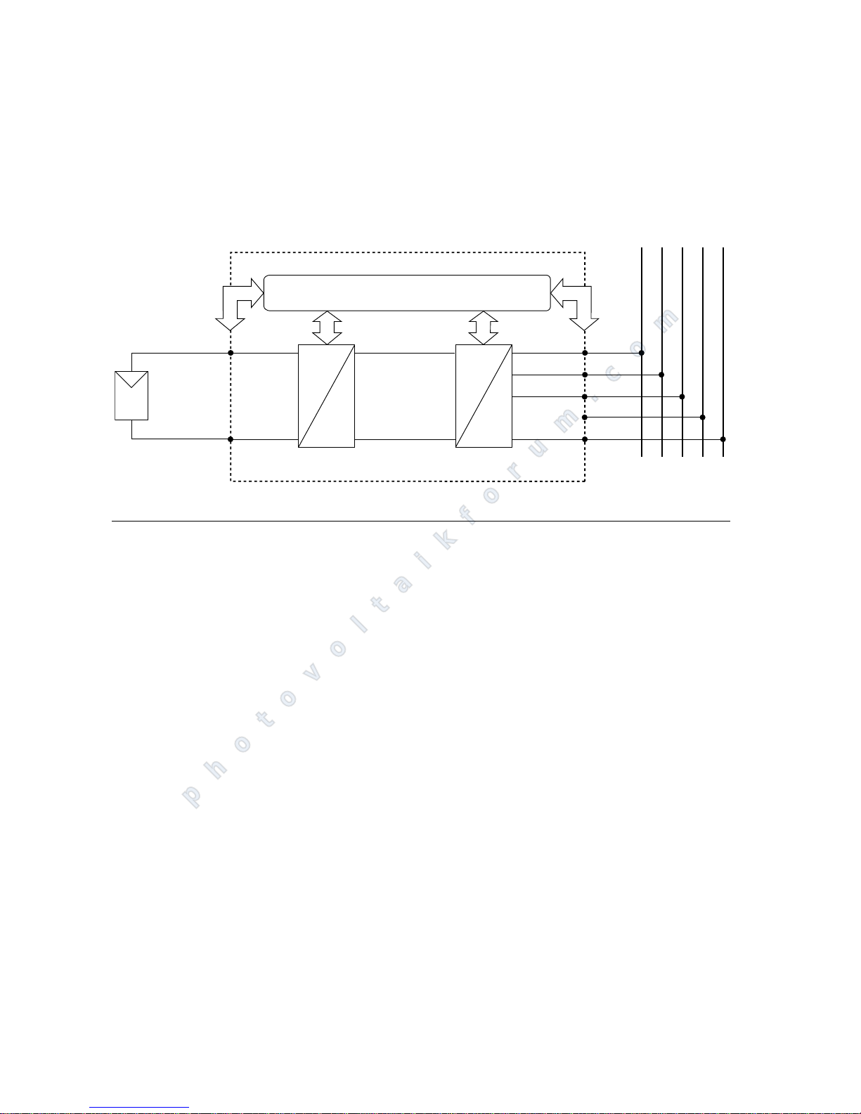
Design PT 30k to PT 33k The basic configuration is shown in the block diagram.
The solar generator voltage connected to the inverter input is initially adapted
by the DC actuator and then converted to alternating current by the high-efficiency HERIC
®
inverter. The AC connection is made with 5 wires due to the 3-pha-
se feed and passive grid monitoring.
1.3 Integration into solar system
Solar generator configuration The technical data of the selected solar generator must match the PT 30k to PT
33k specification (see Technical Data). Incorrect dimensioning can lead to reductions in the yield and to destruction of the unit.
The Sundim design program from Sunways can be used for this purpose. Sunways Sundim can be found on the enclosed CD-ROM or on our website at http:/
/www.sunways.eu/de/.
Be sure to take the following points into account before planning your system:
Watch the celestial alignment of the modules. In Central Europe a maximum
yield is achieved with a module tilt of 30 to the horizontal and direct south
orientation of the solar generator
field.
The cell output decreases as the module temperature increases. Install your
solar generator with sufficient ventilation at the rear.
Check your solar generator approx. every three years for soiling. This occurs
especially on the lower edge of the modules and forms a haze that cannot
be washed off even by heavy rain. Yield reduction can be prevented by
cleaning the modules with a wet cloth or a brush.
Avoid shading of individual modules or solar cells in your system. This can
lead to major reductions in yield.
Please note the maintenance intervals of the inverter. See servicing schedule
on enclosed product CD.
=
=
=
~
L1
L2
L3
PE
N
L1 L2 L3 PE N
–
+
DC+
DC–
Control and monitoring
DC actuator HERIC
®
inverter
Solar generator
Network
photovoltaikforum.com
Page 11
Product description
PT 30k to PT 33k 9
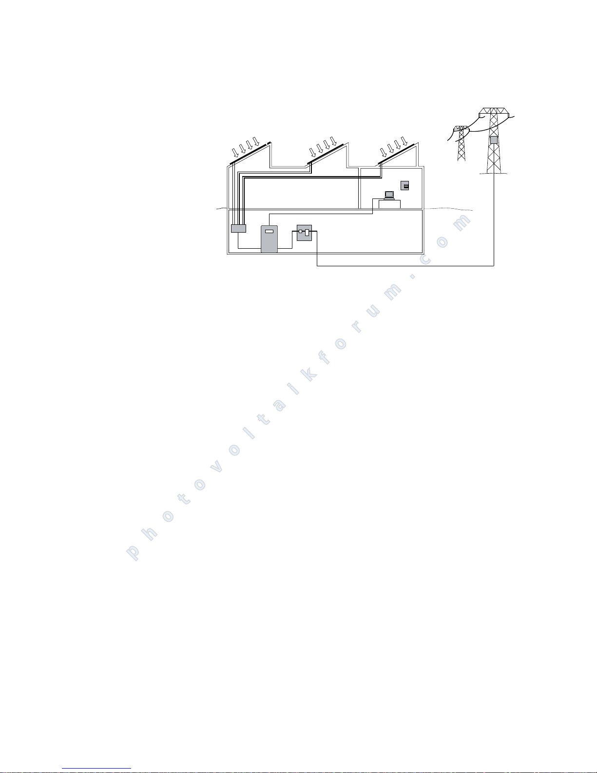
Standard components of a solar system
Depending on the recommendations of your PV planning expert, your PV system consists of the following components:
1 Solar generator
2 Generator connection box (string
box)
3 Solar Inverter with integrated DC
load break switch
4 Mains fuse, AFI type B and energy
meter
Options
5 Irradiance sensor with integrated
temperature sensor
6 PC for monitoring system
7 Large display
1
5
6
4
7
DC
AC
2
3
photovoltaikforum.com
Page 12
Product description
10 PT 30k to PT 33k
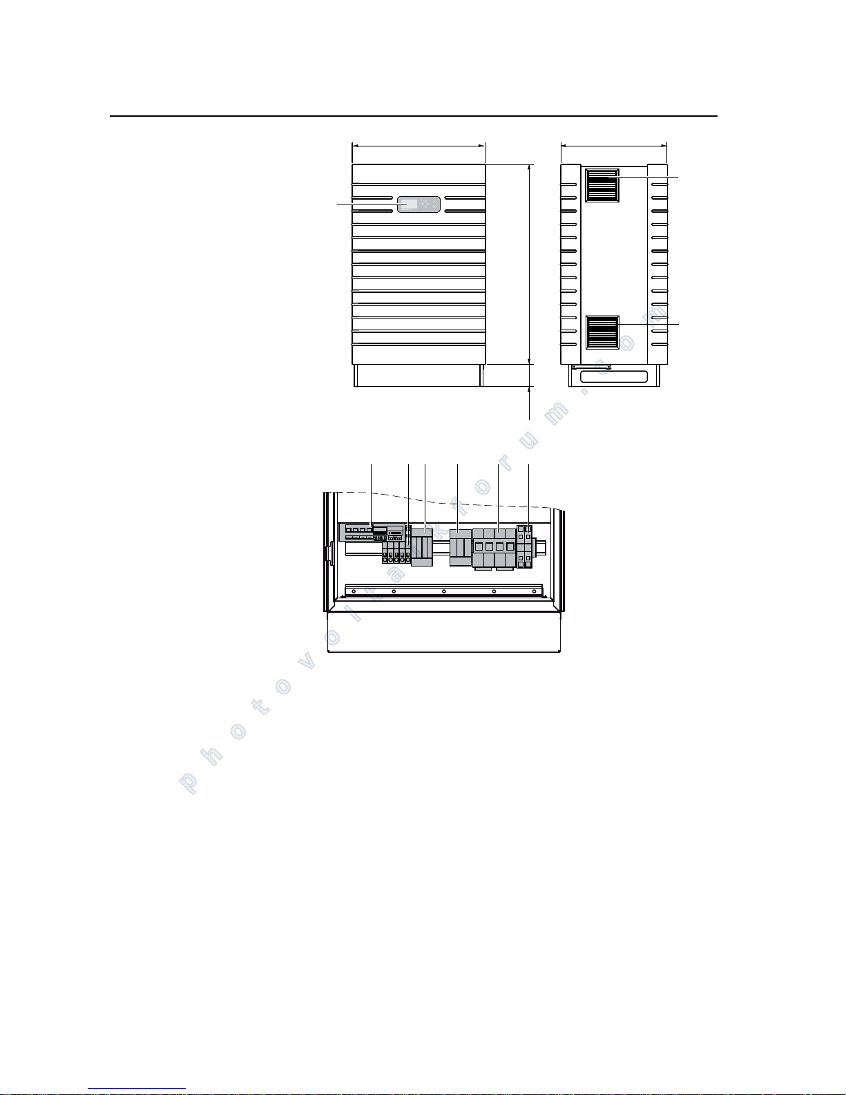
1.4 Module description
Diagram: IP 42 and IP 54 variants
1 Control panel with LCD display,
operating LED and console
2 Fan guard + filter cartridge
3 Communication interfaces
4 AC connection
5 AC overvoltage protection Cat. II
6 DC overvoltage protection Cat. II
(optional)
7 DC load break switch
8 DC connection
L3 L2 L1 N PE
1
600
478
2
900100
3
5746 8
2
photovoltaikforum.com
Page 13
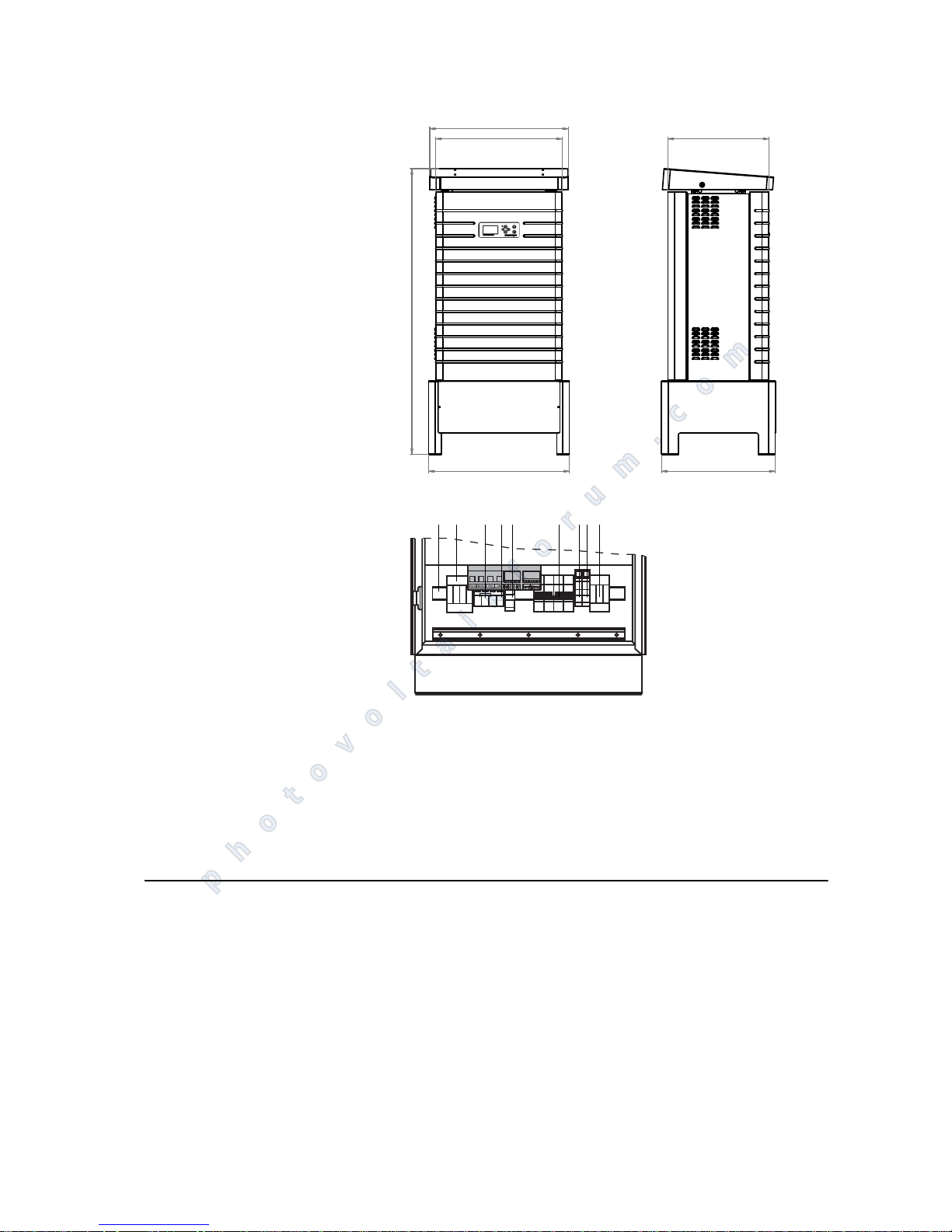
Product description
PT 30k to PT 33k 11
Diagram: IP 5
5/Outdoor variant
1 Mounting rail
2 AC overvoltage protection
3 AC connection L3, L2, L1
4 AC connection N
5 AC connection PE
6 DC load break switch
7 Solar generator Minus
8 Solar generator Plus
9 DC overvoltage protection Cat. II
1.5 Delivery scope
The delivery consists of:
Solar Inverter of the PT series
CAN terminating resistor connector (connected)
Ethernet cable, 3 m (CAT 5e, 1:1)
Control cabinet key
Warranty card
Installation Instructions - SETUP
1360
670
540
480
660
600
1
34529
76
8
photovoltaikforum.com
Page 14
Product description
12 PT 30k to PT 33k
CD-ROM, including Sunways Sundim design program, product and service in-
formation
Checking delivery Before shipment our products are checked for proper condition. Despite care-
ful, recyclable packing, transport damage may occur, for which the transport
company is generally responsible.
Please check the Solar Inverter thoroughly on delivery.
Should you discover damage to the packing or the Solar Inverter, please inform
the transport company immediately. Your specialist dealer will be happy to provide assistance if required. Any damage report must be received by the transport company in writing no later than seven days after receipt of the goods.
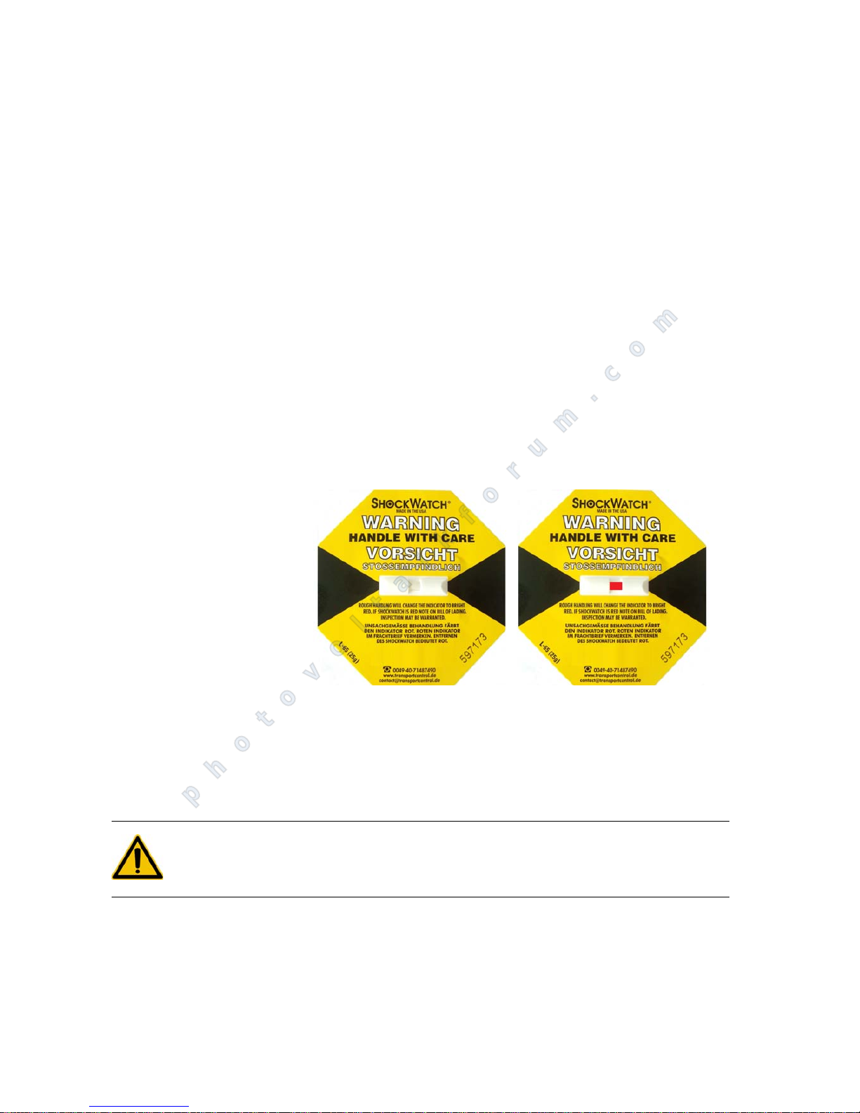
Note regarding delivery A "shock watch" is located on the outer packaging and on the inside of the in-
verter.
Removal of the shock indicator inside the unit is prohibited and immediately voids the guarantee!
Diagram: Shock watch - left: not triggered! Right: triggered!
If the shock watch has been triggered on delivery, please note this on the delivery documentation before you take the unit from the forwarding agent (example: "Shock watch was triggered on delivery") and report the triggered
shock watch with identification number and Solar Inverter serial number immediately to the technical hotline.
DANGER
Never put the unit into operation as it could be functionally damaged.
photovoltaikforum.com
Page 15

Safety precautions
PT 30k to PT 33k 13
2 Safety precautions
2.1 General safety precautions
Follow the instructions in the
operating manual.
Safe handling and trouble-free operation of the PT 30k to PT 33k inverter requires knowledge of the basic safety precautions.
This user manual contains the most important information for operating the
system safely.
Each person concerned with the installation, commissioning, maintenance and
operation of the inverter must have read and understood the entire user manual and, in particular, the chapter entitled Safety Precautions.
In addition, the rules and regulations for accident prevention applicable for the
operating site/plant must be observed.
Risks associated with handling
the Solar Inverter PT 30k to PT
33k
The Solar Inverter has been built in accordance with the state of the art and the
recognised safety rules and may only be used
for its intended purpose and
in a safe condition.
Improper use may lead to dangers to the life and limb of the user or others, or
can adversely affect the system or other property.
In case of malfunctions which can impair safety, the system must be shut down
immediately and secured against being switched on again. The malfunction
must then be eliminated immediately.
Warranty and liability The Sunways General Terms and Conditions of Sale and Delivery always apply.
Warranty and liability claims for personal injury or damage to property are excluded if they were caused by one or more of the following:
Improper use of the inverter
Improper installation, commissioning, operation and maintenance
Operation of the inverter with defective and/or non-operational safety and
protective equipment
Failure to observe the information in the user manual regarding installation,
commissioning, operation and maintenance
Unauthorised modifications
Inadequate monitoring of wearing parts
Improper repairs
Emergencies caused by external influence or force majeure
Defective shock indicator
Faulty operation over a time period of at least one week
Operation in an unsuitable environment (see classification of air quality)
photovoltaikforum.com
Page 16
Safety precautions
14 PT 30k to PT 33k
2.2 Explanation of symbols and warnings
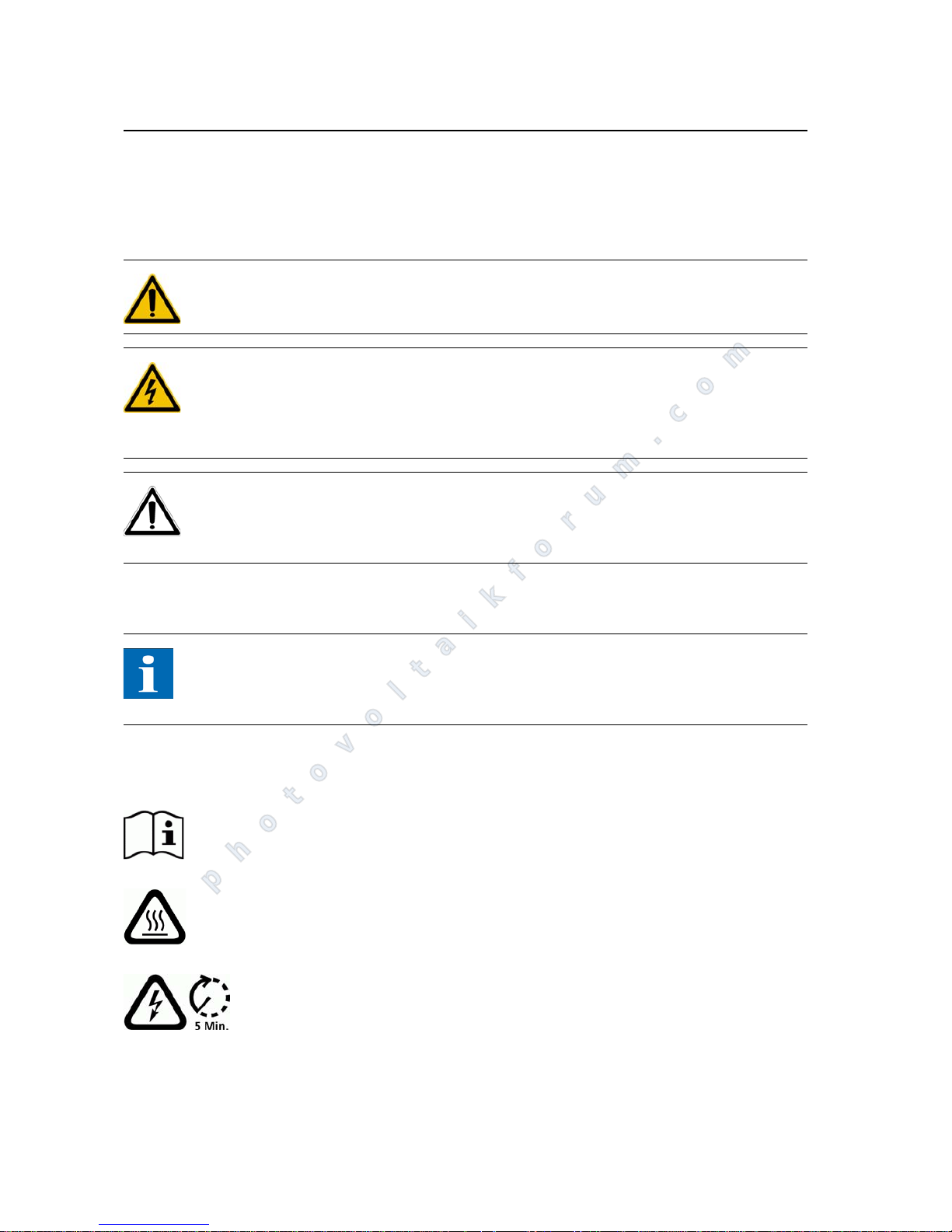
The following warnings and symbols are used to help you quickly understand
this manual and safely use the Solar Inverter.
Warnings used in this user manual
DANGER
This symbol indicates an immediate danger which will result in death, injury or
serious damage if the applicable safety regulations are not followed.
DANGER
Extreme danger from electric shock!
This symbol indicates an immediate danger from electric shock which will result
in death, injury or serious damage if the applicable safety regulations are not
followed.
CAUTION
CAUTION
This symbol indicates an immediate danger which can result in damage if the
applicable safety regulations are not followed.
Symbols used in this user manual
NOTE
Information
This symbol indicates important information which contributes to a better understanding of the inverter.
Warnings and symbols on unit The following warnings on the inverter housing indicate hazards. Always obser-
ve the warnings exactly.
This symbol indicates that the user manual must be read and understood before
putting the unit into operation.
Hot surface! The housing can heat up during operation.
Always disconnect the unit from the mains supply and the PV generator before
opening the cover. The unit still carries life-threatening voltage for approx. five
minutes internally and at the connection terminals of the PV generator following disconnection from the PV generator. The energy storage capacitors are
not completely discharged until after this time. You must wait at least five minutes after disconnecting the unit from the mains supply and from the PV generator before opening the unit.
photovoltaikforum.com
Page 17
Safety precautions
PT 30k to PT 33k 15
WARNING
High leakage currents. Be sure to make an earthing connection before connecting the power supply circuit (AC system).
2.3 Basic safety measures
All electrical work on the Solar Inverter must be carried out by a qualified electrician while observing the VDE regulations, national and other regulations.
The protective screen and rear wall may only be removed and maintenance may
only be carried out by persons who are authorised by Sunways.
When circuit breakers are tripped, the cause of the fault must be determined
and eliminated before recommissioning the unit.
Check electrical equipment regularly.
Retighten any loose connections.
Replace damaged lines/cables immediately.
2.4 Safety concept
The following parameters are monitored and displayed continuously and simultaneously by the inverter controller:
DC overvoltage
Overvoltage L1, L2, L3
Undervoltage L1, L2, L3
Stand-alone operation
Overfrequency L1, L2, L3
Underfrequency L1, L2, L3
Surge error (brief overvoltage L1, L2, L3)
DC share in AC current L1, L2, L3
AFI residual current increase > 30 mA
AFI residual current > 300 mA
Overtemperature of heat sink, interior, chokes
When a malfunction occurs, feeding is immediately interrupted and the Solar
Inverter disconnects from the grid by triggering the mains contactor.
The potential-free alarm relay switches (except for grid undervoltage L1).
The following protective equipment is also provided:
Warning! High leakage current,
earth connection essential before
connecting supply.
photovoltaikforum.com
Page 18

Safety precautions
16 PT 30k to PT 33k
Grid-side varistors (class III)
These protect the power semiconductors in case of high-energy, short-term
voltage peaks in the grid and dissipate the energy in the choke in case of a
grid disconnection.
Grid-side overvoltage protection (class III)
Protection against atmospheric overvoltages (e.g. caused by remote strikes
during thunderstorms).
Optional grid-side overvoltage protection (class II)
Protection against atmospheric overvoltages (e.g. caused by remote strikes
during thunderstorms).
photovoltaikforum.com
Page 19
Technical data
PT 30k to PT 33k 17
3 Technical data
Model PT 30k PT 33k
Article no. with/without DC overvoltage
protection
with/without DC overvoltage
protection
IP 42 (pre-configured for Germany) SI330P11B / SI330P21B SI333P11B / SI333P21B
IP 54 (pre-configured for Germany) SI330P31B / SI330P41B SI333P31B / SI333P41B
IP 5
5 / Outdoor (EU device) SI330P20B / SI330P40B SI333P20B / SI333P40B
DC input
Rated DC output 31000 W 34500 W
Maximum DC current 75.0 A
Nominal DC voltage 700 V
MPP voltage range 420 V to 800 V 460 V to 800 V
Maximum DC voltage 1000 V
DC connection 2 terminal blocks 16-35 mm
(outdoor: 16-70 mm)
Number of MPP trackers 1
Overvoltage category II (according to DIN VDE 0110 Part1)
Lightning protection level SPD Typ 2 (class 2, VDE 0185-305-4) in variant with DC-OVP
AC output
Rated AC output 30000 W 33333 W
Maximum AC output 30000 W 33333 W
Rated AC current 43.5 A per phase 48.3 A per phase
Maximum AC current 50.0 A per phase 53.0 A per phase
Nominal frequency 50 Hz
Frequency range 47.5 - 51.5 Hz (according to DIN VDE 0126-1-1/A1)
Grid voltage 400 V
AC voltage range -20% to +15% (according to DIN VDE 0126-1-1)
Distortion factor < 4%
Power factor (Cos Phi) 1 or configurable between -0.9 and +0.9
Grid voltage monitoring Three-phase (according to DIN VDE 0126-1-1)
Earth fault protection AFI (AC/DC sensitive) according to DIN VDE 0126-1-1
Insulation, frequency and DC current monitoring
Integrated according to DIN VDE 0126-1-1
Required phases for grid connection 3 (L1, L2, L3, N, PE)
AC connection 5 terminal blocks 16 to 25 mm
(IP 55/outdoor: 16 to 70 mm)
AC overvoltage category III (according to DIN VDE 0110 Part1)
Lightning protection level SPD Typ 2+3 (class 2+3, VDE 0185-305-4)
photovoltaikforum.com
Page 20
Technical data
18 PT 30k to PT 33k
Performance data
Stand-by consumption < 4 W
Night-time consumption < 0.1 W
Maximum efficiency 98.0 % 98.0 %
Max. European efficiency 97.6 % 97.6 %
MPP efficiency (static) 99.9 % 99.9 %
Circuit type HERIC
®
topology, three-phase, transformerless
Other features
DC switch according to IEC 60947-1/3 Integrated
DC overvoltage protection Depending on variant
Grid-connection fuse layout 3 x 63 A (16 mm
) / AFI type B
Data interfaces Ethernet, CAN, potential-free signalling relay, S0, modem, RS485
Sensor interfaces Irradiance, temperature
Display LCD dot matrix, backlit, 128 x 64 pixels
System monitoring Automatic alarms via e-mail, Sunways browser, Sunways portal
Power supply unit protected on PCB T2A/250 V
IP rating according to IEC 60529 IP 42 / IP 54 (outdoor: IP 55)
Max. relative humidity 95% / non-condensing
Air quality according to EN 60721-3-4 for mechanical active substances: 3S1-IP 42, 3S2-IP5
5/Outdoor
for chemical active substances: 4C1-IP42, 4C1-IP55/Outdoor
Climate class 4K4H (in accordance with EN 60721--4)
Maximum height above sea level 1000 m
Cooling Forced cooling by fan (fresh air supplied: approx. 350 m
3
/ hour)
Ambient temperature -20C to 40°C (to 50°C with derating)
Stiffening plates on the sides for installations in direct sunligt (optionally available,
Art.Nr.SE104M10A)
Overload characteristics Operating point offset
Dimensions (height x width x depth) 100 x 60 x 48 cm (outdoor: 136 x 67 x 54 cm)
Weight approx. 155 kg (outdoor: approx. 170 kg)
Installation type Standing installation
Noise level Approx. 70 dBA (outdoor: approx. 76 dBA)
Standard warranty (option) 5 years (with service contract: up to 20 years)
Certificates CE, DIN VDE 0126-1-1/A1, RD 1663/2000, RD 661/2007, CEI 11-20
v.1, Sezione F Guida Enel, BDEW Medium Voltage Directive and
February 2011 addendum, TR 3 (REV. 21) and TR 8 (Rev. 4)
Model PT 30k PT 33k
photovoltaikforum.com
Page 21
Installation
PT 30k to PT 33k 19
4 Installation
4.1 Mechanical installation
Requirements for installation
location
DANGER
The Solar Inverter may not be installed in areas subject to explosion hazards.
The Solar Inverter may not be exposed to corrosive gases.
No combustible materials must be stored within 3 metres of the solar inver-
ter.
Protection against moisture
and foreign bodies
The PT 30k to PT 33k application range varies according to model.
The IP 42 variant is suitable for indoor installation. The air quality must at
least correspond to Class 3S1 for mechanically active substances as well as
Class 4C1 for chemically active substances.
The IP 54 variant can be used for the roofed outdoor area. The air quality
must at least correspond to Class 3S2 for mechanically active substances as
well as Class 4C1 for chemically active substances.
The IP 5
5/Outdoor variant allows outdoor installation. If possible, use a
roof-covered area protected from rain and dust as an installation location
and avoid direct sunlight. The air quality must at least correspond to Class
3S2 for mechanically active substances as well as Class 4C1 for chemically active substances.
Stiffening plates on the sides optionally available.
Classification of air quality for
mechanically active substances
(acc. to EN 60721-3-4)
Environmental conditions for site-specific
use
Class
3S1 3S2 3S3 3S4
a) Sand in air [mg/m
3
] - 30 300 3000
b) Dust (suspended matter content) [mg/m
3
] 0.01 0.2 0.4 4.0
b) Dust (rainfall) [mg/m
3
]0.41.51540
Locations where the occurrence of dust is
kept to a minimum through appropriate
measures.
xxxx
Locations where no special measures for reducing the sand or dust occurrence have
been taken and are not close to sand.
xxx
Locations close to sources of sand or dust. x x
Locations in production facilities where there is no sand or dust, or locations in geographical regions where a higher proportion of
sand and dust can occur in the air.
x
photovoltaikforum.com
Page 22
Installation
20 PT 30k to PT 33k
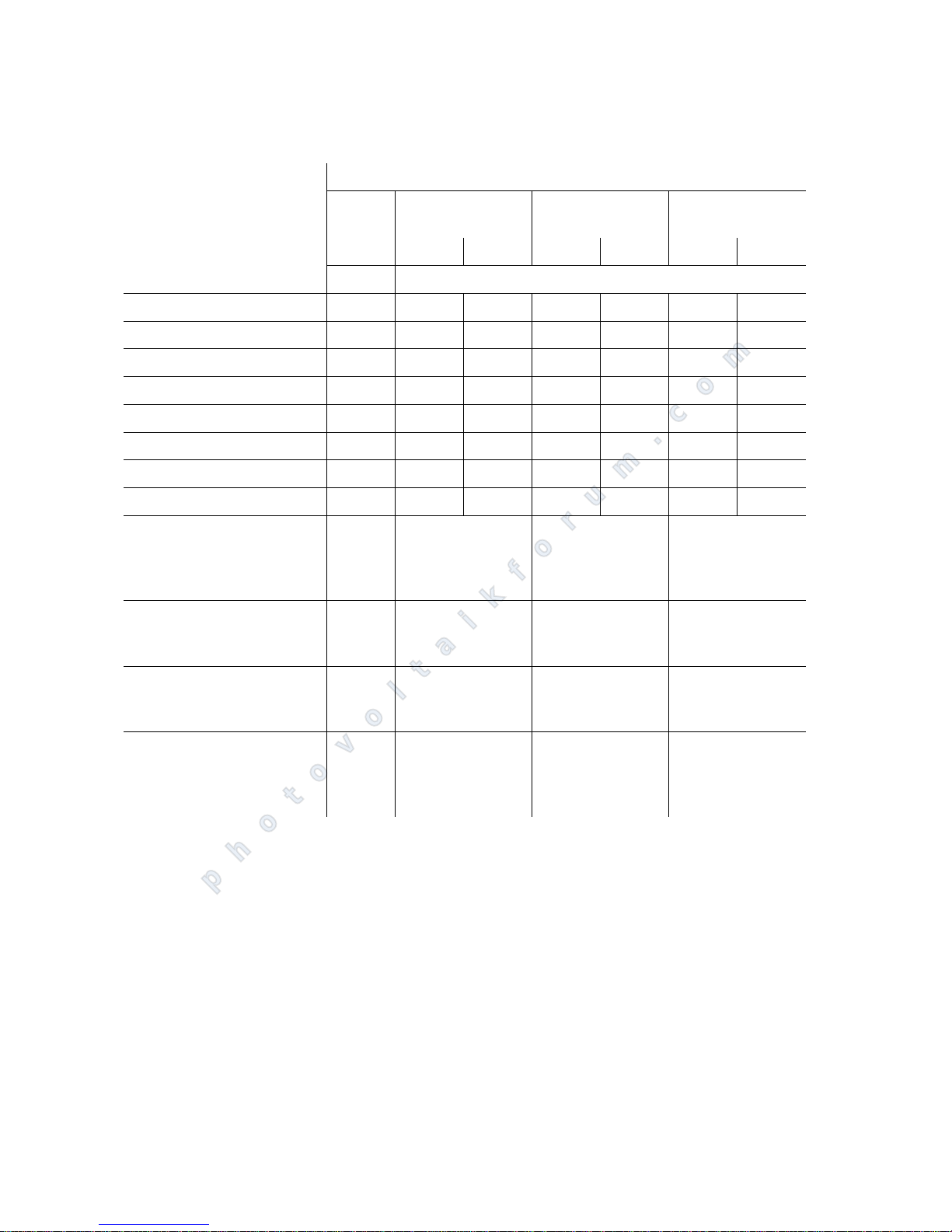
Classification of air quality for
chemically active substances
(acc. to EN 60721-3-4)
Mechanical load-bearing capacity
Note during installation that the Solar Inverter weighs 155 kg or 170 kg (IP
54/Outdoor variant). The installation surface must be firm and able to carry
this weight in the long term. A concrete foundation is recommended.
Thermal interaction The installation surface and the rear and side walls of the installation site
must consist of flame-retardant material (not suitable: surface of wood or
plastic; suitable: e.g. concrete), as the frame of the PT 30k to PT 33k can heat
up to a maximum of 85C.
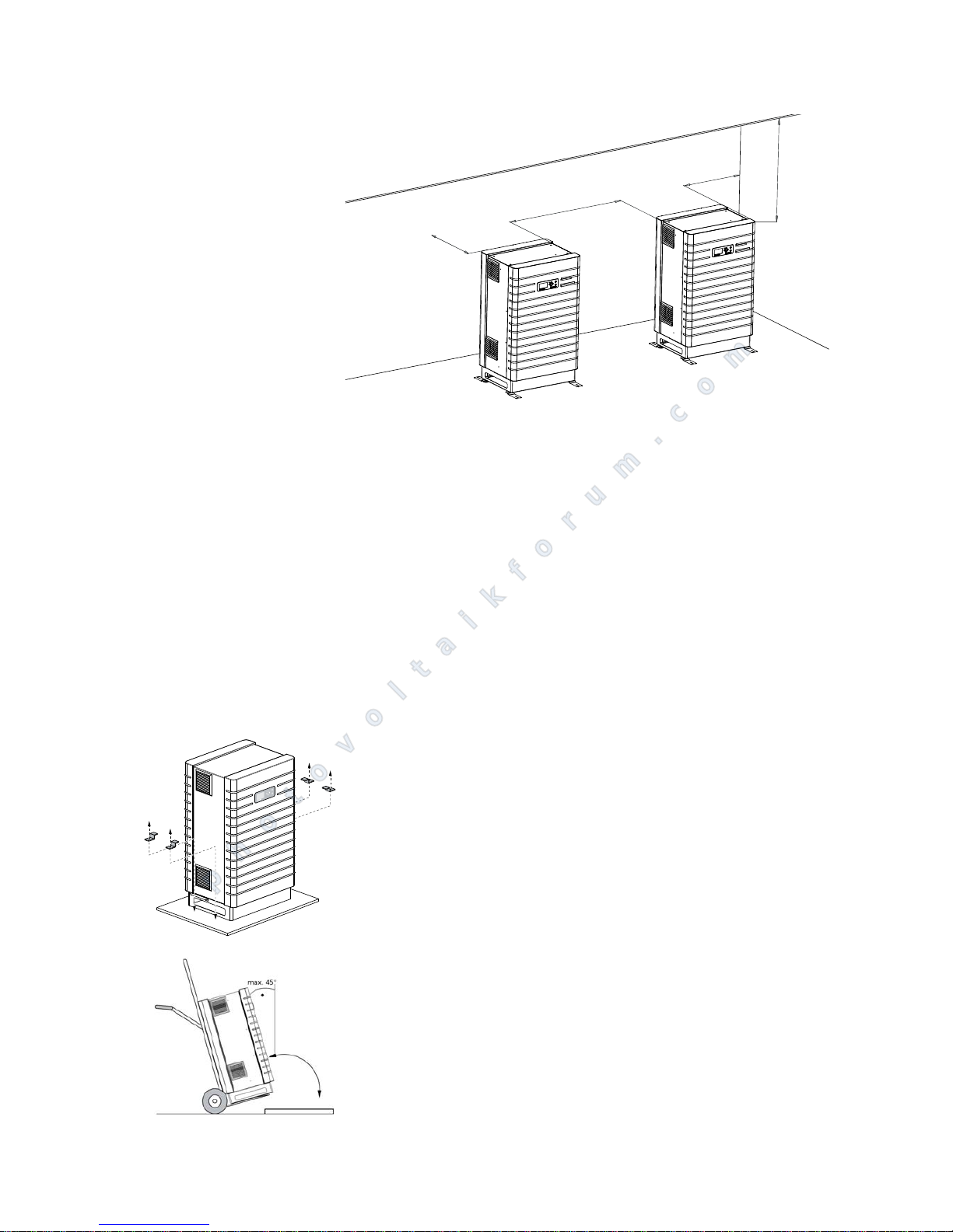
A minimum distance of 1 m to other units, cabinets, ceilings, cable ducts, etc.
must be maintained to the sides of the housing. A distance 0.3 m must be
maintained from the rear wall of the PT 30k to PT 33k for service purposes
(see diagram).
Environmental conditions for
site-specific use
Class
4C1 4C2 4C3 4C4
Limit Average Limit Average Limit Average Limit
a) Sea salt Occurrence of salt spray
b) Sulphur dioxide, mg/m3 0.1 0.3 1.0 5.0 10 13 40
c) Hydrogen sulphide, mg/m3 0.01 0.1 0.5 3.0 10 14 70
d) Chlorine, mg/m3 0.1 0.10.30.31.00.63.0
e) Hydrogen chloride, mg/m3 0.1 0.10.51.05.01.05.0
f) Hydrogen fluoride, 0.003 0.01 0.03 0.1 2.0 0.1 2.0
g) Ammonia, mg/m3 0.03 1.0 3.0 10 35 35 175
h) Ozone, mg/m3 0.01 0.05 0.1 0.1 0.3 0.2 2.0
i) Nitrogen oxides, mg/m3 0.1 0.5 1.0 3.0 9.0 10 20
Locations in rural or also
densely populated regions
with little industry or moderate traffic density.
x xxx
Locations in densely populated
regions with industry and high
traffic density.
xx
Locations in the immediate vicinity of industrial plants with
chemical emissions.
xx
Locations inside industrial
plants, emissions of dangerous
chemical substances in high
concentrations.
x
photovoltaikforum.com
Page 23
Installation
PT 30k to PT 33k 21
The Solar Inverter must be installed upright to enable adequate free convec-
tion.
Solar Inverter may not be stacked in order to prevent excessive warming.
If several PT Solar Inverter are operated in an enclosed space, adequate fresh
air supply must be ensured. Larger systems should be configured in collaboration with Sunways at the design stage.
The ambient temperature must be between -20 C and +40 C. At ambient
temperatures above 40C, the Solar Inverter automatically regulates its output downwards.
The IP 42 and IP 54 variants should not be exposed to direct sunlight to pro-
tect them from unnecessary external warming. The outdoor version is protected by a sun shade for operation in direct sunlight.
Installation (IP 42, IP 54 variants)
For Solar Inverter installation, proceed as follows:
1. The Solar Inverter is attached to the pallet with retaining claws. Remove the
retaining claws.
2. Use a trolley for transporting the unit to the installation site.
3. Use the retaining claws to secure the Solar Inverter on the installation surface.
Do not subject inverters to extreme shocks, otherwise the internal shock indicator will be activated (>25 g acceleration) and the unit guarantee thus rendered void.
1
0
0
0
0
5
0
0
1
0
0
0
5
0
0
photovoltaikforum.com
Page 24
Installation
22 PT 30k to PT 33k
Installation (IP 5
5/Outdoor va-
riant)
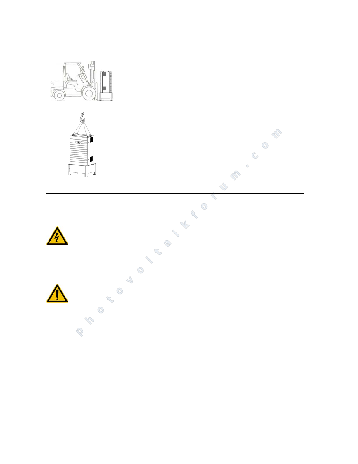
Proceed as follows to install the PT 30k to PT 33k outdoors:
1. The Solar Inverter is attached to the pallet with retaining claws. Remove the
retaining claws.
2. Use a forklift truck, a wheel loader or crane to transport the unit to the installation site.
3. Secure the Solar Inverter on the installation surface (e.g. on a concrete base)
with the screws included in the delivery contents. Use the pressed-on hole
template in the cover for this.
Do not subject inverters to extreme shocks, otherwise the internal shock indicator will be activated (>25 g acceleration) and the unit guarantee thus rendered void.
4.2 Electrical installation
Cable installation (IP 42, IP 54
variants)
DANGER
Extreme danger from electric shock!
Touching live parts can result in death.
All electrical work must be carried out by a qualified electrician while obser-
ving the VDE regulations, national and other regulations.
DANGER
For units with cable entry terminals that are installed externally or in rooms
where small rodents are to be expected (e.g. mice in factory buildings), the
installation of rodent protection is obligatory. Otherwise the warranty becomes void.
Even with installation of the rodent protection, a rodent infestation cannot
be 100% excluded.
Rodent protection is only included as standard in the IP54 variant. For the IP
42 variant, it can, however, also be ordered and retrofitted separately (Art.
No. SE103M10A).
photovoltaikforum.com
Page 25
Installation
PT 30k to PT 33k 23
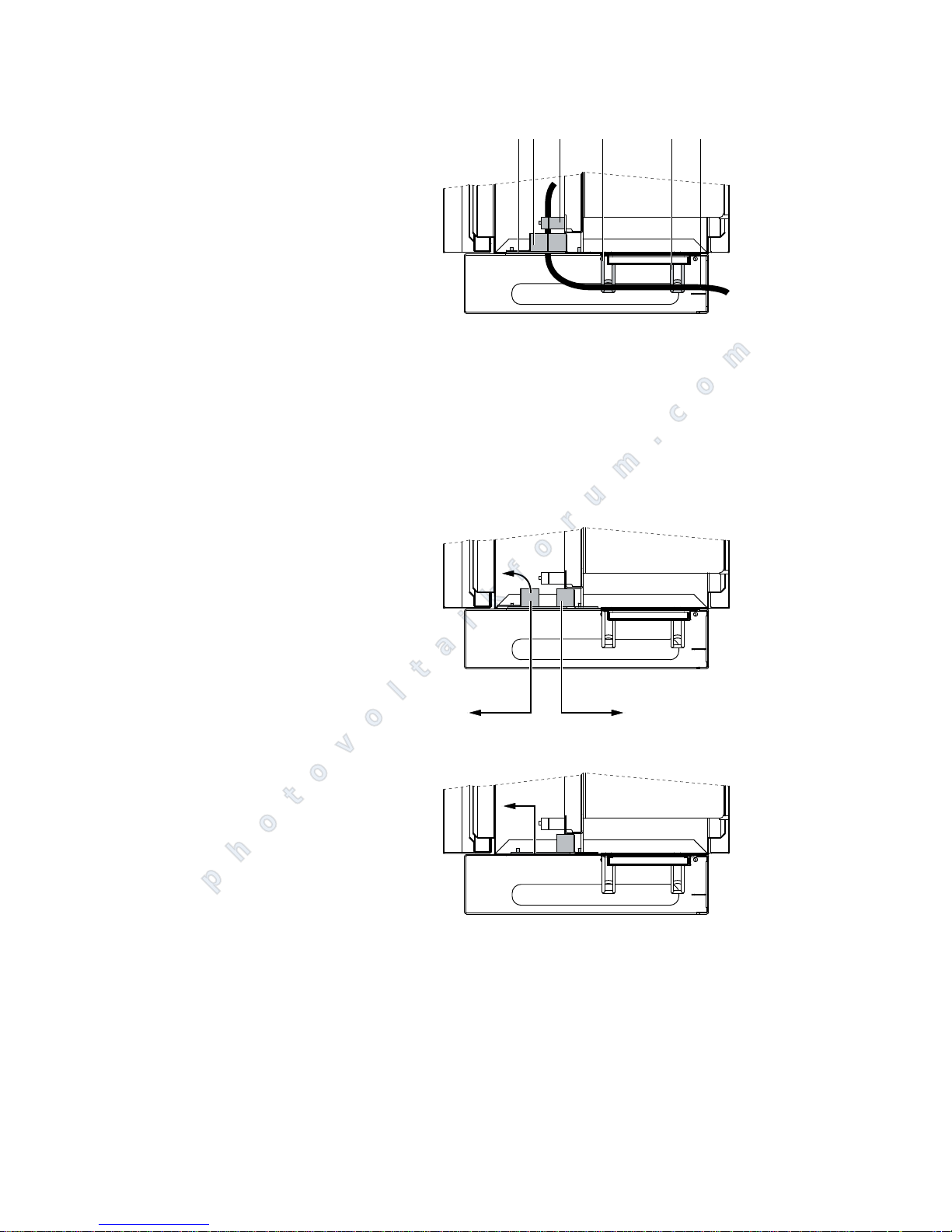
Cable installation IP 42, IP 54
1 Rodent protection (only included
as standard in the IP54 variant)
2 Bars with foam rubber
3 Strain relief device
4 Cable brackets
5Cable
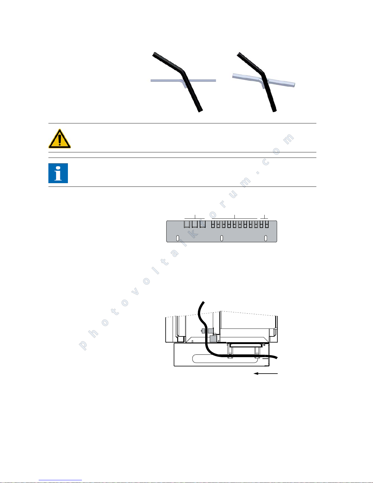
Proceed as follows with the cable installation for the IP 42 and IP 54 variants:
1. Release the screws of the foam strips, push them apart and remove the front
part of the foam strip.
2. Remove the rodent protection. Note the mounting position!
3. Only bend the punch-outs on the rodent protection, which are needed for
the cable. To ensure the cable can optimally fitted, remove just the half of a
punch-out where necessary.
3 4 4 521
photovoltaikforum.com
Page 26
Installation
24 PT 30k to PT 33k
DANGER
Use a tool (e.g. pliers) to bend the punch-outs in order to avoid injury.
NOTE
The individual ribs of the rodent protection should be bent along the length of
the cable and should not be broken!
4. Configuration of the rodent protection:
1 Punch-outs for AC cables
2 Punch-outs for interface cables
3 Punch-outs for DC cables
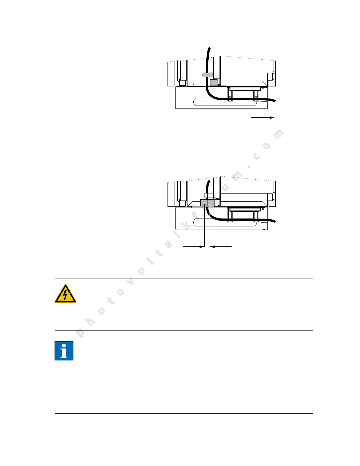
5. Guide the cable on the Solar Inverter back over the cable brackets through
the opening of the unit in front of the rear foam strip.
6. Open the strain relief device and guide the cables through it.
7. Install the cables (see Solar generator connection and Grid connection).
8. Pull the cables back slightly and re-attach them with the strain relief device.
321
photovoltaikforum.com
Page 27
Installation
PT 30k to PT 33k 25
9. Re-insert the rodent protection in the unit housing. Note the correct mounting position and ensure that the cables are routed exactly through the bent
punch-outs.
10.Replace the front part of the foam strip.
11.Push the bars back together and secure them with the bolts.
Cable installation (IP 5
5/Out-
door variant)
DANGER
Extreme danger from electric shock!
Touching live parts can result in death.
All electrical work must be carried out by a qualified electrician while obser-
ving the VDE regulations, national and other regulations.
NOTE
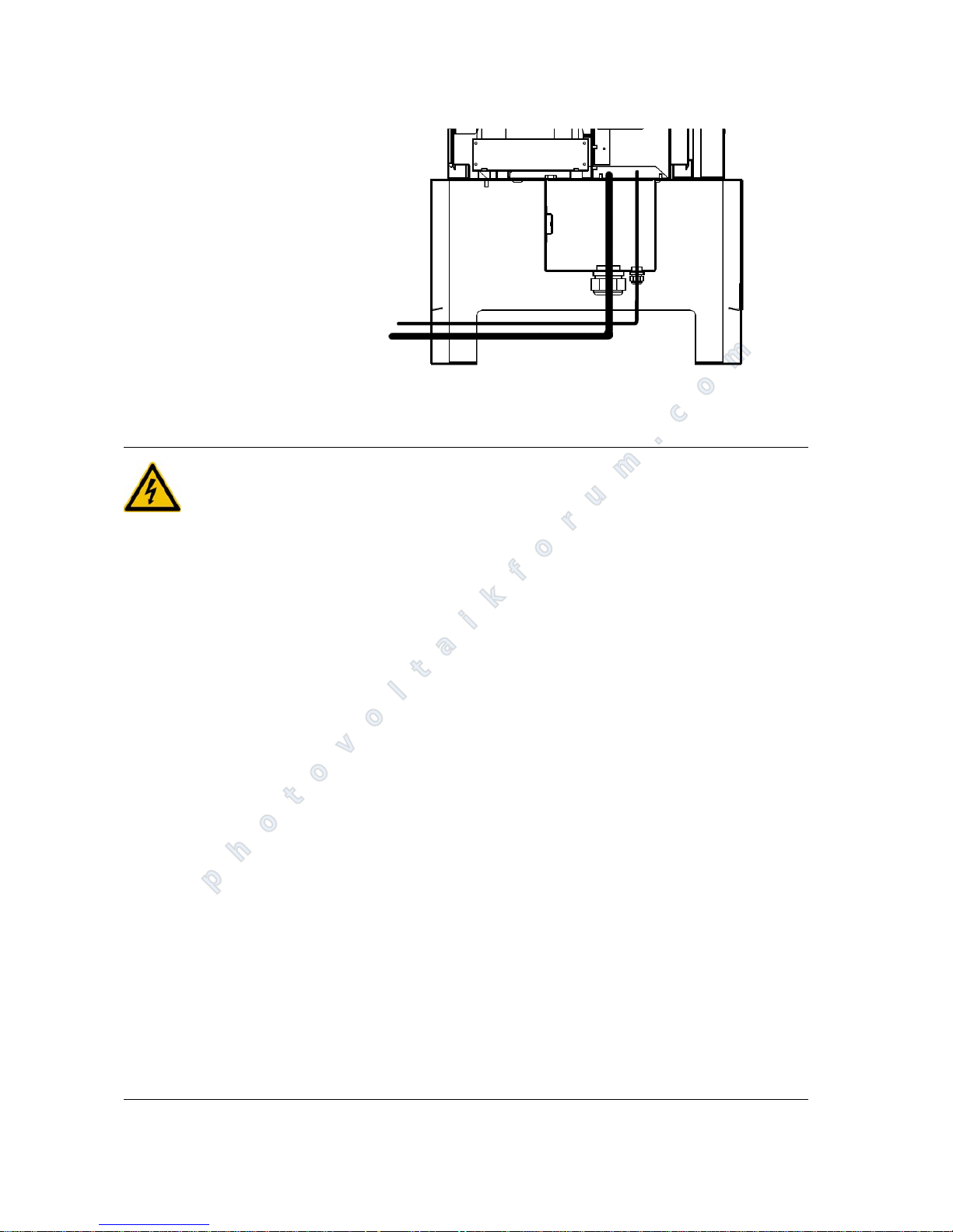
Correct cable installation
The unit only meets all requirements of housing protection class IP 54/Out-
door if all cable entries have been screwed in properly.
In the case of unused cable entries, the connection area must be closed with
the blank plugs included.
Unclosed openings in the connection box of the unit can lead to damage
caused by moisture, dust or animals. This renders the guarantee void!
photovoltaikforum.com
Page 28
Installation
26 PT 30k to PT 33k
Fig. 1: IP 5
5/Outdoor illustration: Cable entry
Solar generator connection
DANGER
Extreme danger from electric shock!
Touching live parts can result in death.
All electrical work must be carried out by a qualified electrician while obser-
ving the VDE regulations, national and other regulations.
Execute the direct current wiring in accordance with the system dimensio-
ning of your planning expert.
Prepare all solar generator cables before connecting the solar generator to
the Solar Inverter.
Check each solar generator string for proper operation with an open-circuit
voltage and short-circuit current measurement before connecting the string
to the inverter.
Check the rating plate on the Solar Inverter to ensure that it is approved for
the maximum solar generator voltage.
The positive and negative lines must be kept electrically separate from the
earth potential.
Touchable, live parts of the solar generator (e.g. metal frame, carrying struc-
ture, etc.) must be earthed (connection with PE).
Check the solar generator for freedom from short-circuits to earth.
Before connecting the solar generator to the Solar Inverter, open the integ-
rated DC load break switch (position 0).
After the solar generator is connected to the Solar Inverter and the DC load
break switch is switched on, the direct generator voltage is present internally.
Always disconnect the mains connection first by switching off the correspon-
ding mains fuse and before disconnecting the solar generator side by opening the DC load break switch.
photovoltaikforum.com
Page 29
Installation
PT 30k to PT 33k 27
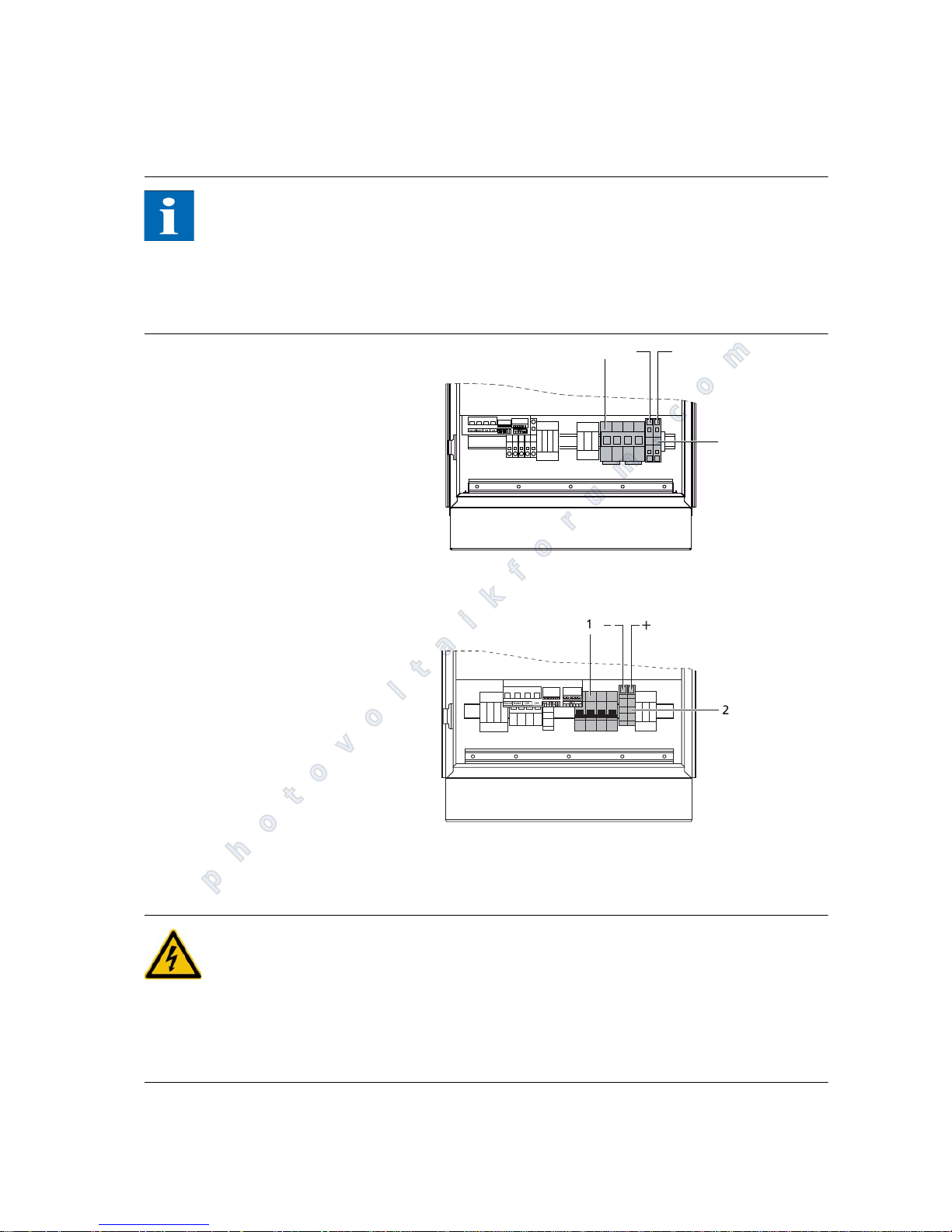
Overview The solar generator can be directly connected to the Solar Inverter with a string.
Use the DC terminals that are accessible from inside for the connection.
NOTE
The solar generator strings running to the string box must be identically di-
mensioned and comply with the specifications of the Solar Inverter.
No external DC load break switch is required. A DC load break switch as re-
quired in accordance with DIN VDE 0100-712 is integrated in the Solar Inverter.
Diagram: IP 42, IP 54 variants
1 DC load break switch 2 Solar generator connection
Diagram: IP 5
5/Outdoor variant
1 DC load break switch 2 Solar generator connection
Installation
DANGER
Extreme danger from electric shock!
Touching live parts can result in death.
All electrical work must be carried out by a qualified electrician while obser-
ving the VDE regulations, national and other regulations.
Ensure that the cables are installed securely.
2
–
+
L3 L2 L1 N PE
1
photovoltaikforum.com
Page 30
Installation
28 PT 30k to PT 33k
NOTE
Any kind of soiling (dust, moisture, etc.) has a negative effect on the termi-
nals with regard to function over the intended period of use.
DC connection cables with cross-sections between 16 mm
and 35 mm or
between 16 mm
and 70 mm for (Outdoor) are permitted.
The copper cables must be double-insulated and UV-resistant ("Radox"
cables from Huber & Suhner, for example, are suitable).
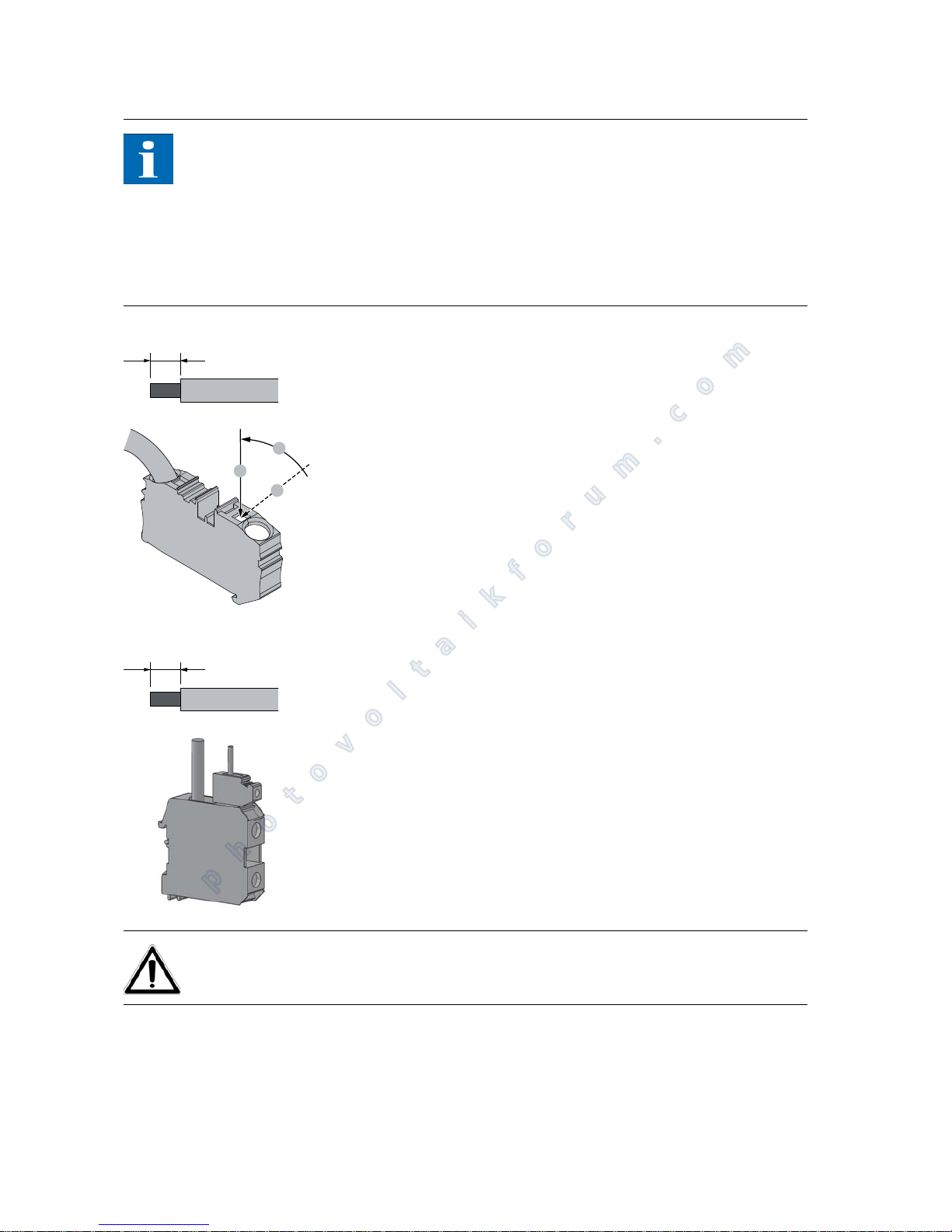
The following sequence must be observed during assembly:
1. Strip the voltage-free line.
with end splice 15 mm
without end splice 20 mm
2. Apply a screwdriver at a slant (A) to the locking device and push it in until
it is vertical (B). The screwdriver then locks it in place (C).
3. Introduce the stripped cable into the cable clamp and push the screwdriver
forward into the original position.
The following sequence must be observed during assembly:
1. Strip the voltage-free line.
2. The IP 54/Outdoor variant has screw terminals. These are fully suited for
copper cables from 16 mm
to 70 mm. The screws to the terminal blocks
must be tightened with a torque of 6-8 Nm. The use of aluminium cables is
only possible for cross sections of 35 mm
-70 mm. Please observe the specifications of the cable/cable socket manufacturer (removal of oxide layer,
use of Vaseline or grease).
CAUTION
Please avoid squeezing the cable insulation or the end splice. Improper connection may damage the equipment!
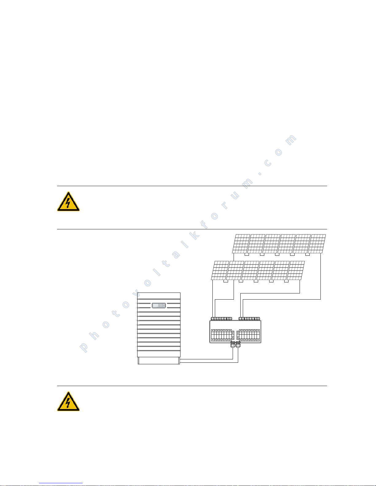
String box The string box enables connection of up to 8 or 12 solar generator strings to a
DC bus line that can be connected directly to the Solar Inverter.
The string box has protection rating IP65 and can therefore also be installed
near the solar generator. The string box can be equipped with fuses or dummy
sleeves. Pay attention to correct installation of metric cable glands and blind
15/20
B
A
C
15/20
photovoltaikforum.com
Page 31
Installation
PT 30k to PT 33k 29
caps as otherwise the watertightness of the IP65 is not guaranteed.
String box options
The Sunways string box is available with the following options:
for up to 8 or up to 12 PV strings
with/without DC overvoltage protection
with/without DC load break switch
fuses for different currents
CAN string box incl. string monitoring
Dummy sleeves
Further information can be found in the Solar Inverter Accessories section at
www.sunways.de.
DANGER
First disconnect the solar generator incl. string box with the aid of the DC
load break switch of the inverter. Only then open the string fuses. Opening
of the string fuse under live conditions can lead to life-threatening arcing!
Mains connection
DANGER
Extreme danger from electric shock!
Touching live parts can result in death.
All electrical work must be carried out by a qualified electrician while obser-
ving the VDE regulations, national and other regulations.
–
+
–
+
12345678 12345678
–
+
+
–
photovoltaikforum.com
Page 32
Installation
30 PT 30k to PT 33k
Note the AC terminal assignment. An incorrect assignment can result in the
unit being destroyed.
No consumers may be connected to the supply line from the Solar Inverter to
the mains fuse.
Always disconnect the mains connection first by switching off the correspon-
ding mains fuse and before disconnecting the solar generator side by opening the DC load break switch.
NOTE
If the voltage on the AC connection exceeds the permissible value due to a long
line length or an insufficient cable cross-section, the Solar Inverter will be disconnected from the mains. In power grids with a low capacity and a high solar
generator output, this can lead to individual Solar Inverter being switched off
and then on again several times.
Overview An AC terminal strip on the underside of the unit is used for the five-wire grid
connection (L1, L2, L3, N, PE) of the solar inverter. Feeding is always three-phase
via the AC terminal.
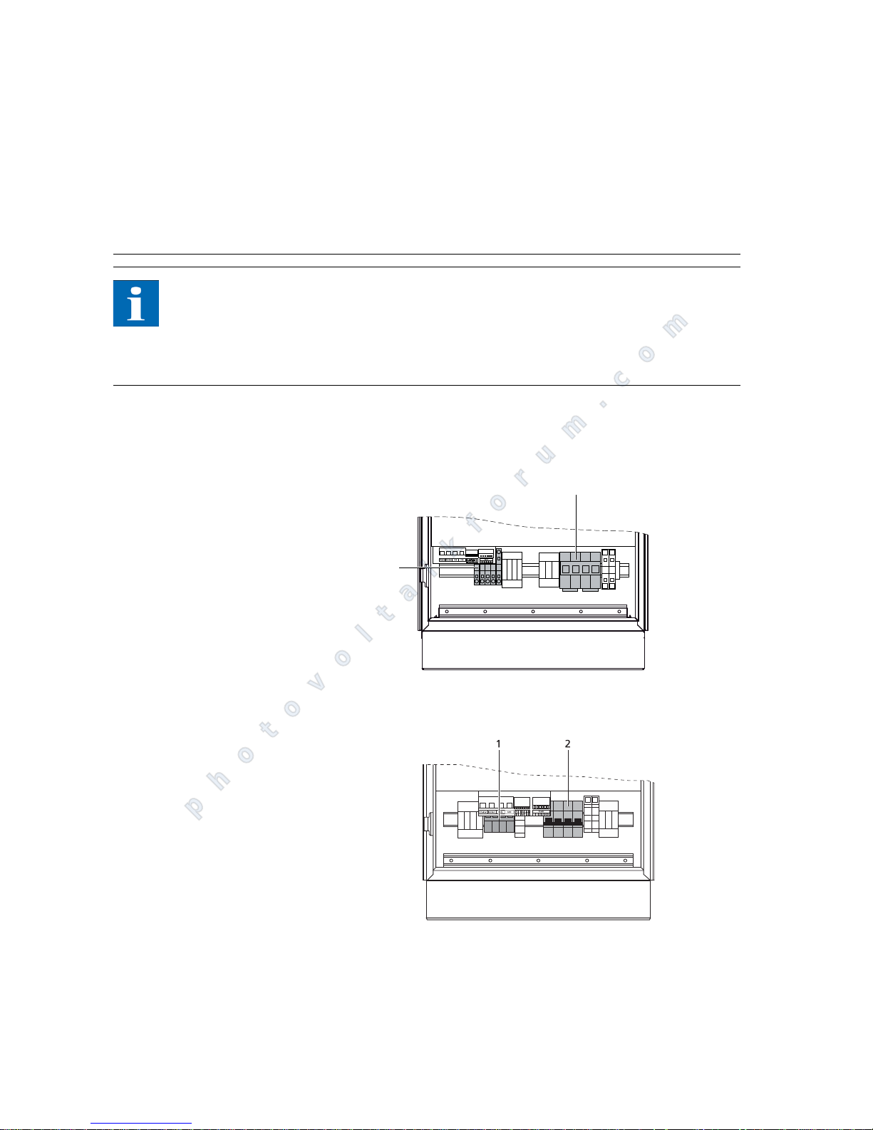
Diagram: IP 42, IP 54 variants
1 AC connection 2 DC load break switch
Diagram: IP 5
5/Outdoor variant
1 AC connection 2 DC load break switch
The unit is centrally earthed using PE terminals. No separate earthing of the solar generator is required.
1
L3 L2 L1 N PE
2
photovoltaikforum.com
Page 33
Installation
PT 30k to PT 33k 31
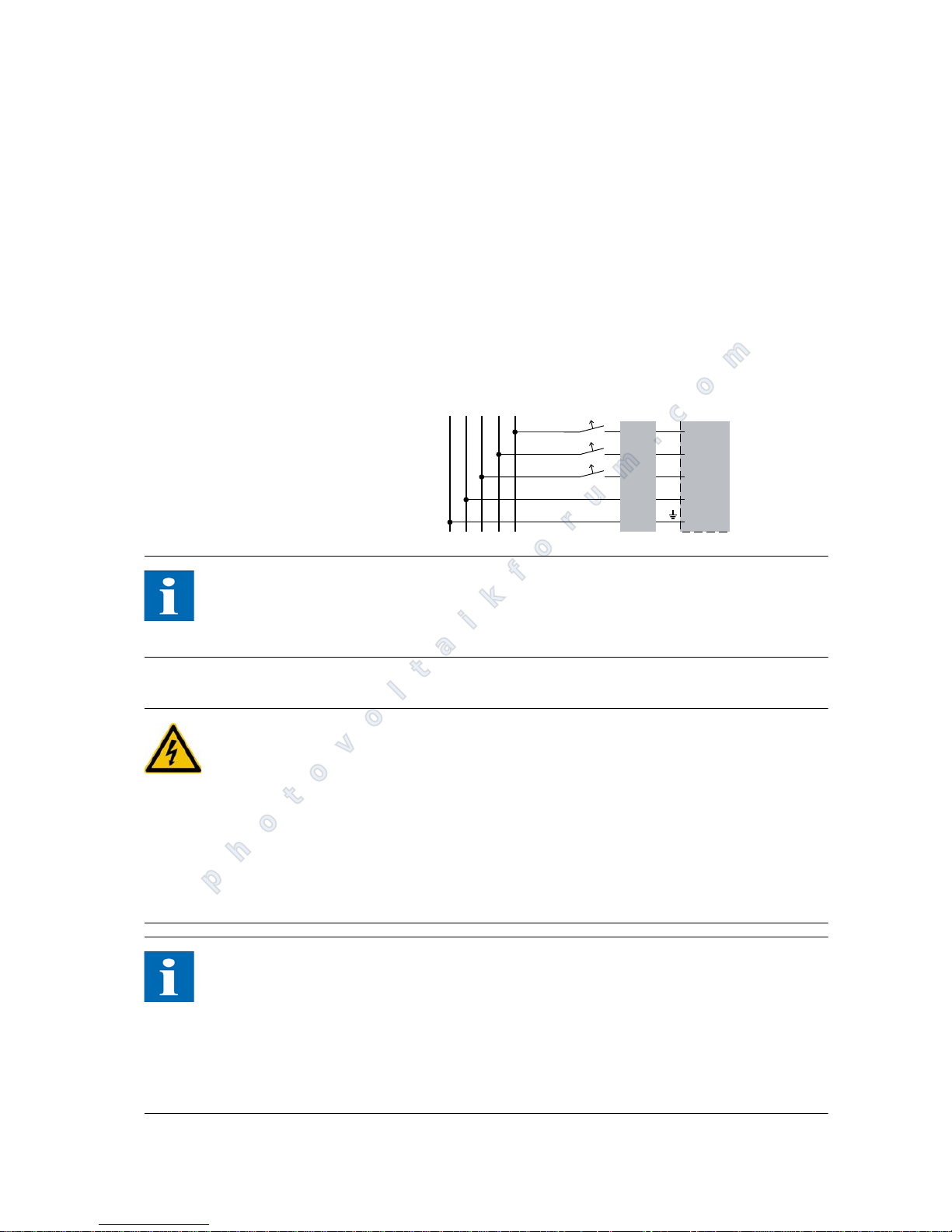
A corresponding circuit breaker is recommended as a line protection element in
the grid feed direction:
3 x 63 A with slow-blow characteristic C
(for connection cross-sections ≥ 16 mm
2
)
A three-pin circuit breaker or individual fuses can be used. Protection is implemented according to the installation method. A guide is provided in the appendix.
An AFI type B must be installed at the mains.
The AC power distribution incl. mains fuse should be placed as close as possible
to the inverter.
NOTE
A three-phase meter must be used.
Some grid operators require the use of a reverse-current-capable meter.
Installation
DANGER
Extreme danger from electric shock!
Touching live parts can result in death.
All electrical work must be carried out by a qualified electrician while obser-
ving the VDE regulations, national and other regulations.
Note the AC terminal assignment. An incorrect assignment can result in the
unit being destroyed.
Ensure that the cables are installed securely.
NOTE
Any kind of soiling (dust, moisture, etc.) has a negative effect on the termi-
nals with regard to function over the intended period of use.
The following cross-sections are recommended as suitable AC connection
cables for power lengths of up to 50 m.
16 mm
solid copper cable
16 mm
flexible copper/non-metallic sheathed cable
PE N L3 L2 L1
1
4
3
2
INVERTER
Mains fuse
AFI TYP B
photovoltaikforum.com
Page 34
Installation
32 PT 30k to PT 33k
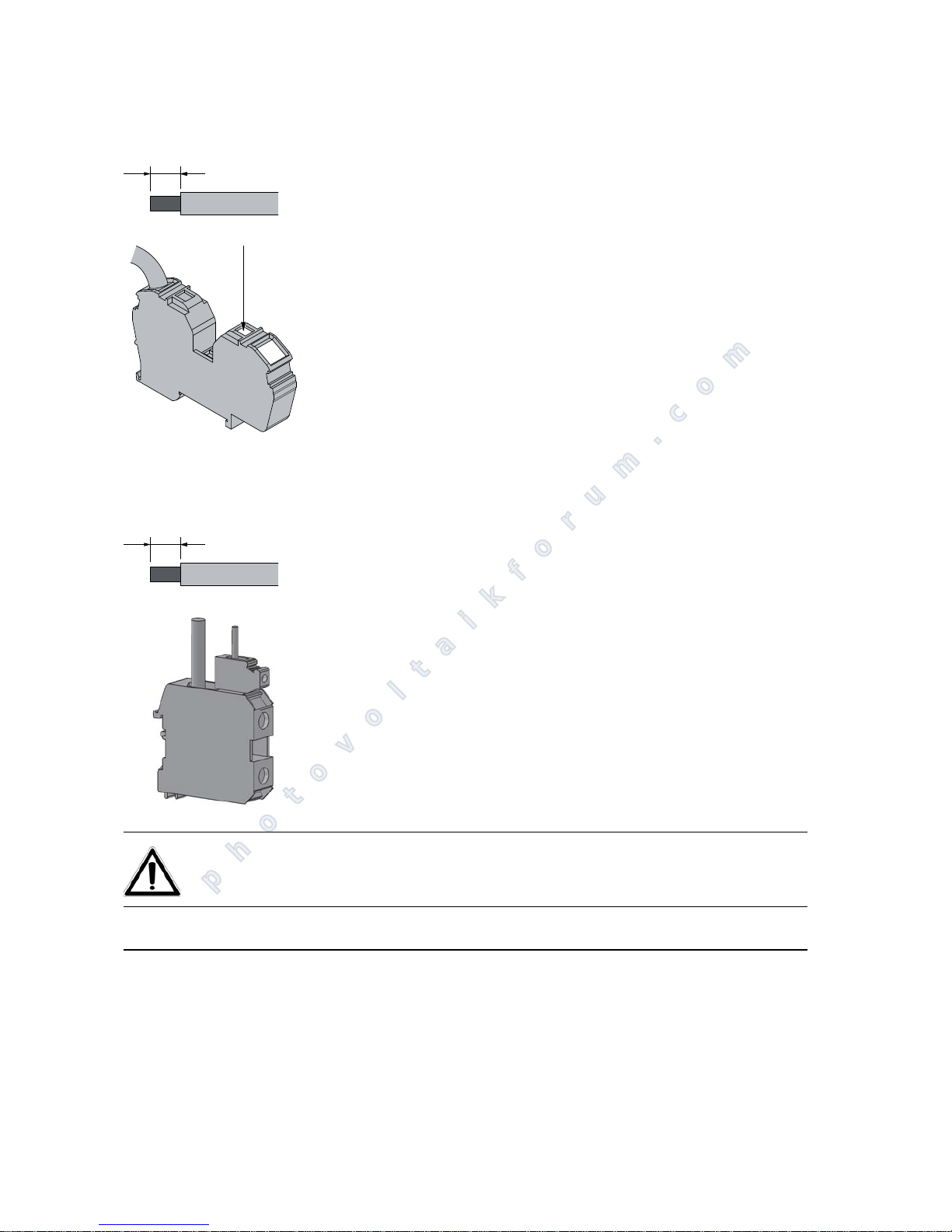
The following sequence must be observed during assembly:
1. Strip the voltage-free line.
with end splice 15 mm
without end splice 20 mm
2. Introduce a screwdriver vertically into the locking device.
3. Introduce the stripped cable into the cable clamp and pull the screwdriver
out again.
The following sequence must be observed during assembly:
1. Strip the voltage-free line.
2. The IP 5
5/Outdoor variant has screw terminals. These are fully suited for cop-
per cables from 16 mm
to 70 mm. The screws to the terminal blocks must
be tightened with a torque of 6-8 Nm. The use of aluminium cables is only
possible for cross sections of 35 mm
- 70 mm. Please observe the specifications of the cable/cable socket manufacturer (removal of oxide layer, use of
Vaseline or grease).
CAUTION
Please avoid squeezing the cable insulation or the end splice. Improper connection may damage the equipment!
4.3 Installing the communication equipment
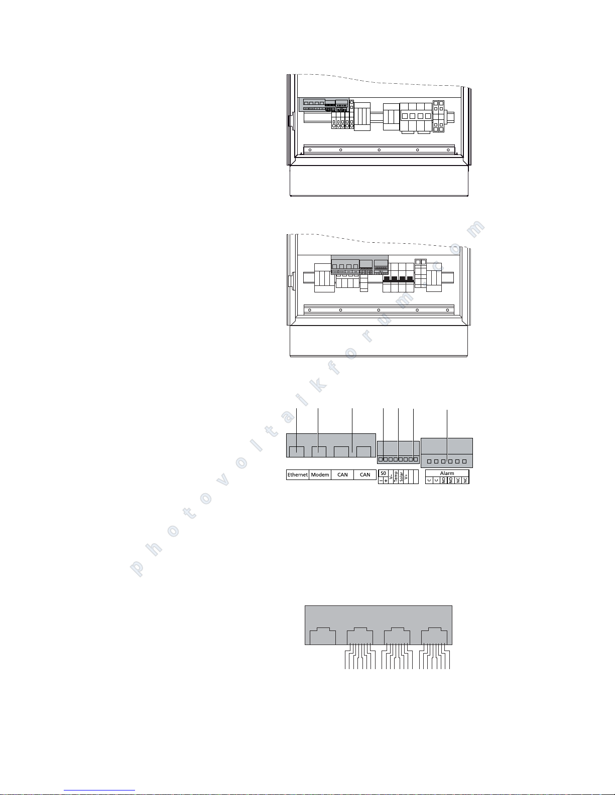
The communication interfaces are located above the AC terminals.
15/20
15/20
photovoltaikforum.com
Page 35
Installation
PT 30k to PT 33k 33
Diagram: IP 42, IP 54 variants
Diagram: IP 5
5/Outdoor variant
Interface overview
1 Ethernet connection
2 Modem connection
3CAN bus
4 S0 interface (pulse output, e.g. for
large display)
5 Terminal for temperature and irra-
diance sensor
6 RS485 for external data logger
7 Connection for alarm relay
All screw connections should be tightened with a max. of 0.5 Nm.
Pin assignment
The connectors for the CAN interfaces and for the modem interface have the
following pin assignment:
CAN and modem
L3 L2 L1 N PE
2
13 754
RS485-
RS485+
6
Ethernet Modem CAN CAN
2
1346578
2
1346578
2
1346578
photovoltaikforum.com
Page 36
Installation
34 PT 30k to PT 33k
Networking of Solar Inverter
via CAN bus
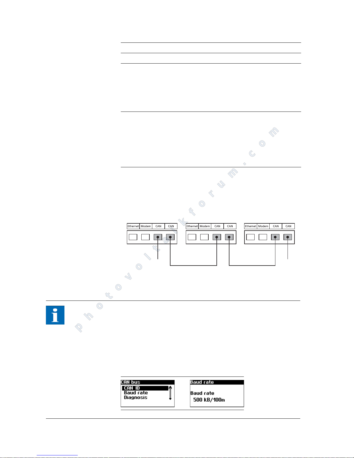
The Solar Inverter from the NT (900 V), AT and PT series can be networked via
the CAN bus interface. Use the included Ethernet cable to network the Solar Inverter with each other. Connect a terminating resistor at the first and last Solar
Inverter in the series. The pluggable terminating resistors are contained in the
delivery scope.
1 Terminating resistor connector
NOTE
Solar Inverter from the PT series are provided with a default setting of 125 kbit/
s as standard. In contrast, Solar Inverter in the AT and NT series have a default
setting of 500 kbit/s.
When networking units from different series, the bit rate must be configured
identically in all units. This adjustment can be made either on the display of the
Solar Inverter or in the Sunways browser.
Bit rate adjustment via the display menu: Settings – Network – CAN bus – Baud
rate
CAN Modem
Pin Description Meaning Description Meaning
1N.C. >1 TXh
2 CAN_GND 0 V / GND >2 TX1
3 CAN_H Bus line (domi-
nant high)
<3 RXh
4 CAN_L_T Termination -4 VCC
5 CAN_H_T Termination -5 GND
6 CANL Bus line (domi-
nant low)
<6 RXI
7 CAN_SHLD optional CAN
shield
<7 R1h
8N.C. <8 R1I
11
photovoltaikforum.com
Page 37
Installation
PT 30k to PT 33k 35
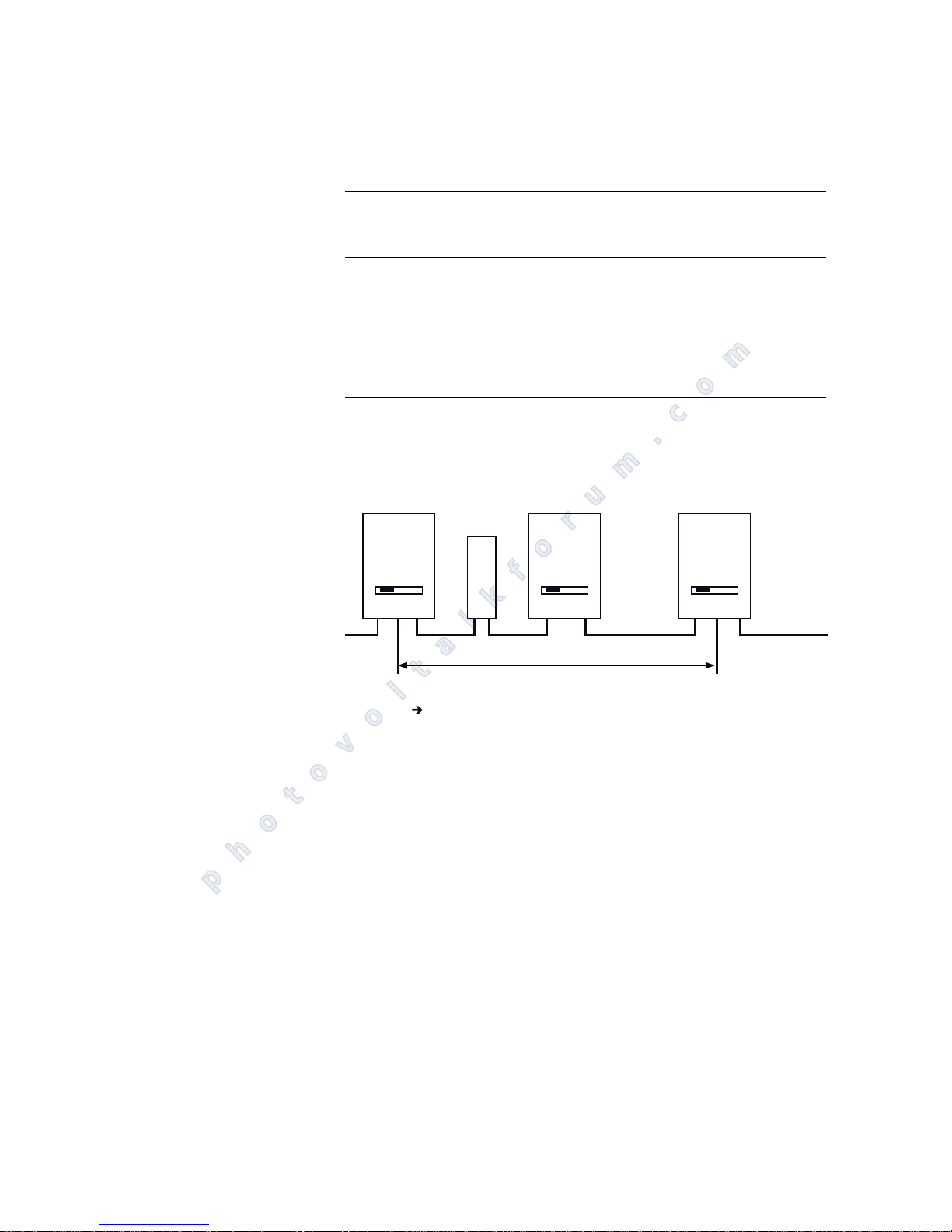
Up to 99 NT, PT and AT series units can be networked via a CAN bus. The following table shows the recommended cable cross-sections depending on bus
length and number of nodes:
If the values in the table cannot be maintained, the signal must be strengthened
with the installation of a CAN bridge, with which the length of the CAN bus can
be extended up to 500 m. Bus length, number of nodes and the cable cross-section thus influence the way in which a CAN bridge is used.
You can purchase the CAN bridge from Sunways - please contact the Technical
Hotline.
The CAN bridge divides the bus into two physically independent segments. This
maximum cable length of each segment is determined by the bit rate set. Therefore with a bit rate of 125 kbit/s, it is possible to have two segments with a maximum length of 500 m respectively. The total cable length can thus stretch up
to 1 km in ideal cases.
To do this, if a system has a unit from the PT series, then the CAN bridge can be
directly integrated into the PT Solar Inverter over which a 24 V DC power supply
unit can be supplied with electricity. If a system has single-phase units of the
Sunways, the CAN bridge can be integrated into the AC power distribution. In
this instance, an external 24 V DC supply is necessary (power consumption 1.5
W).
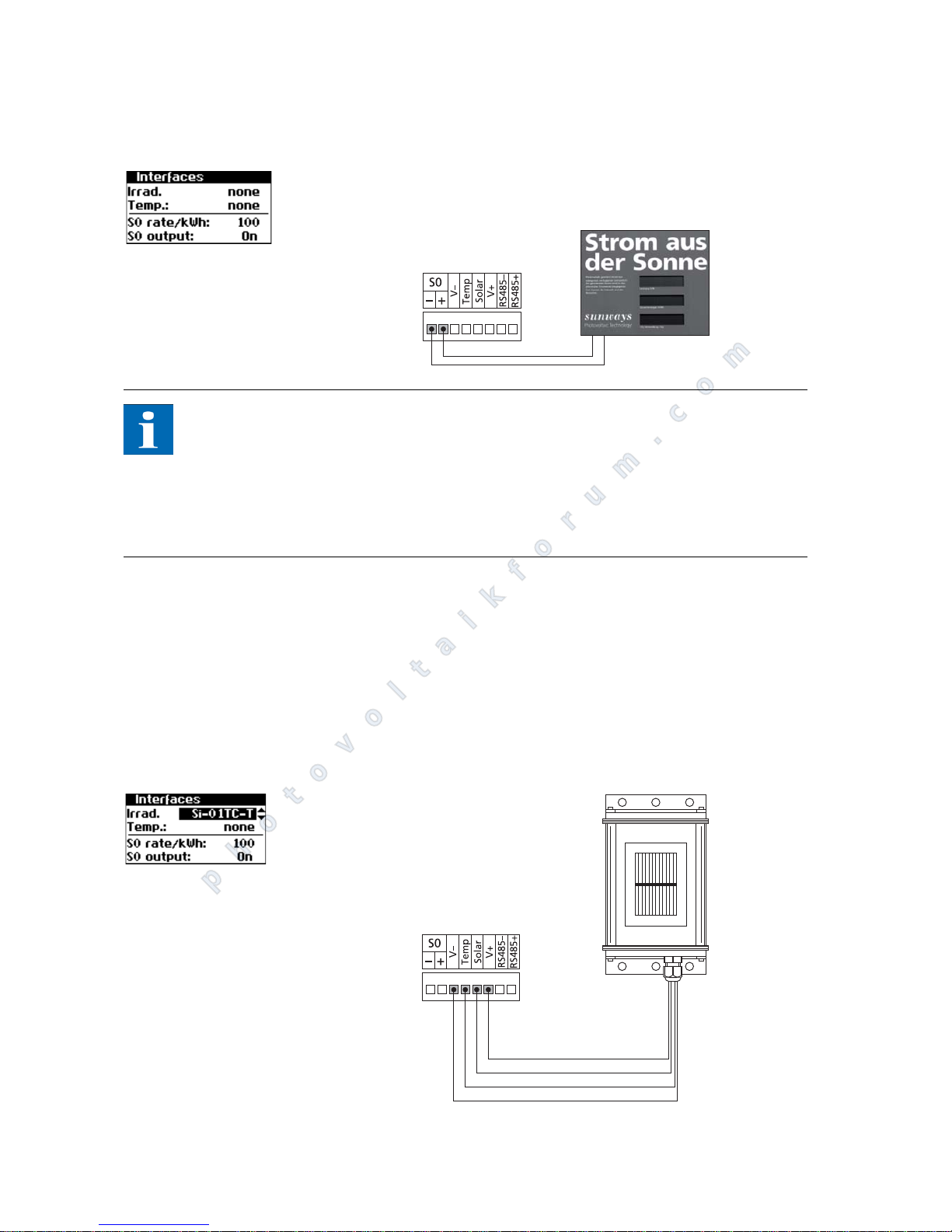
S0 interface The S0 pulse output enables, for example, the connection of a large display
(Sunways display) for displaying the momentary output, the energy yields and
the CO
2
reduction.
Bus length/
Number of nodes
Bit rate 32 64 99
100 m 500 kbit 0.25 mm
or
AWG 24
0.25 mm or
AWG 24
0.25 mm or
AWG 24
250 m 250 kbit 0.34 mm
or
AWG 22
0.5 mm or
AWG 20
0.5 mm or
AWG 20
500 m 125 kbit 0.75 mm
or
AWG 18
0.75 mm or
AWG 18
1.0 mm or
AWG 16
CAN bus
Inverter
XX
Inverter
XX
Inverter
XX
CAN bridge
Network length / number of nodes / cable cross-section
outside table values
Use of one or several CAN bridges
photovoltaikforum.com
Page 38
Installation
36 PT 30k to PT 33k
You can use the S0 interface on the master if you want to transmit the entire
line yields as a sum to a large display.
The S0 interface is adjusted via the display on the inverter. Open the menu "Settings - Networking - Interfaces".
NOTE
Please note that the maximum pulse rate may not be greater than 15 pulses/
sec. Calculate the pulse rate depending on the size of the solar system using
the following formula:
Pulse rate [pulses/kWh] = 50,000 / system size [kWp]
The pulse rate must be set on your Solar Inverter and on the large display.
Temperature and irradiance
sensor
The optional addition of an irradiance sensor (model Si-01TC-K from Ingenieurbüro Mencke & Tegtmeyer) with an integrated PT-100 temperature sensor for
temperature measurement enables the acquisition of irradiation data and the
corresponding module temperature and storage in the internal data memory as
a 5-minute mean value. This additional measuring unit helps analyse the system
output. Based on the values, any errors on the PV generator, e.g. shading or failure of solar cells, can be detected.
The sensor is activated via the display. In the menu Settings - Network - Interfaces, you can select the sensor type in the Irrad. and Temp. field.
photovoltaikforum.com
Page 39
Installation
PT 30k to PT 33k 37
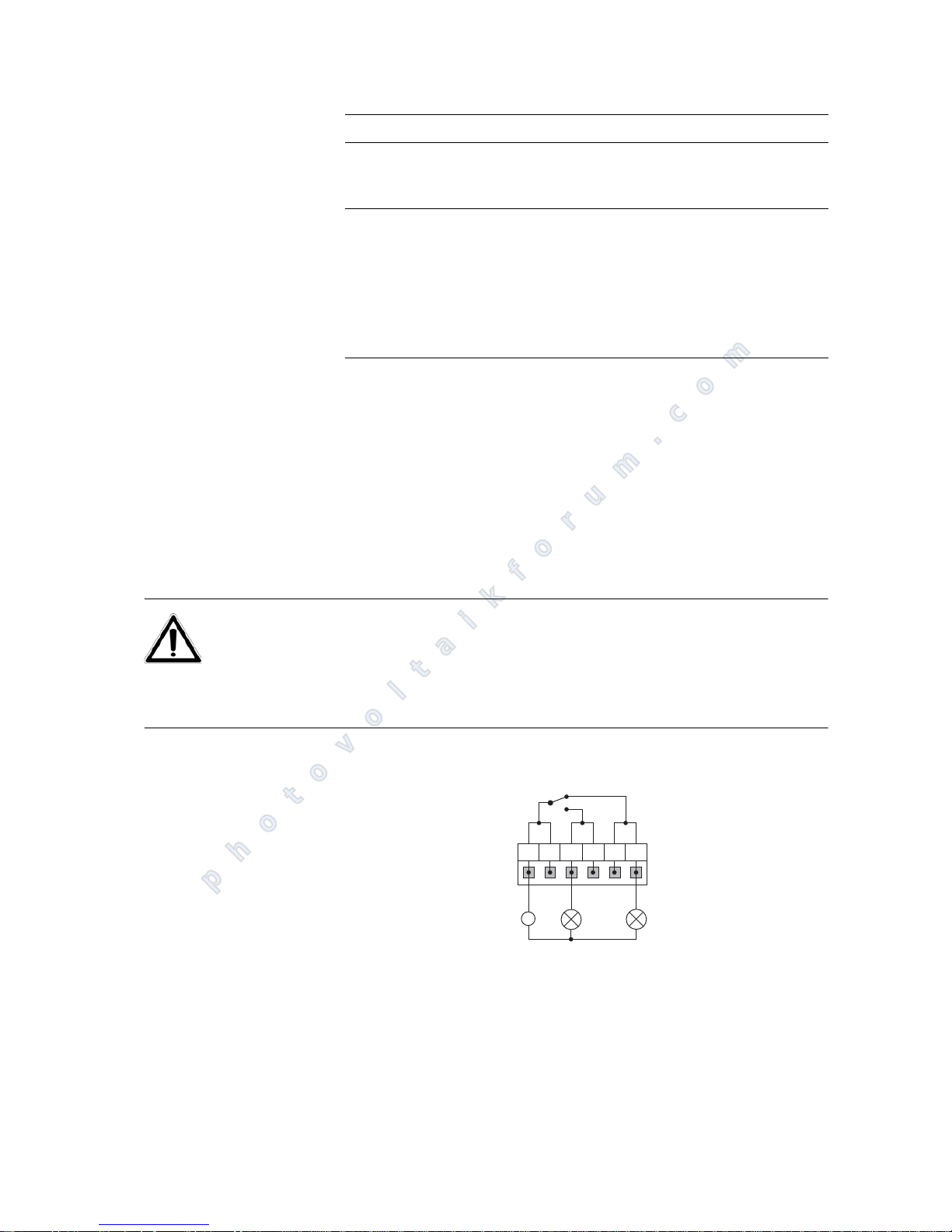
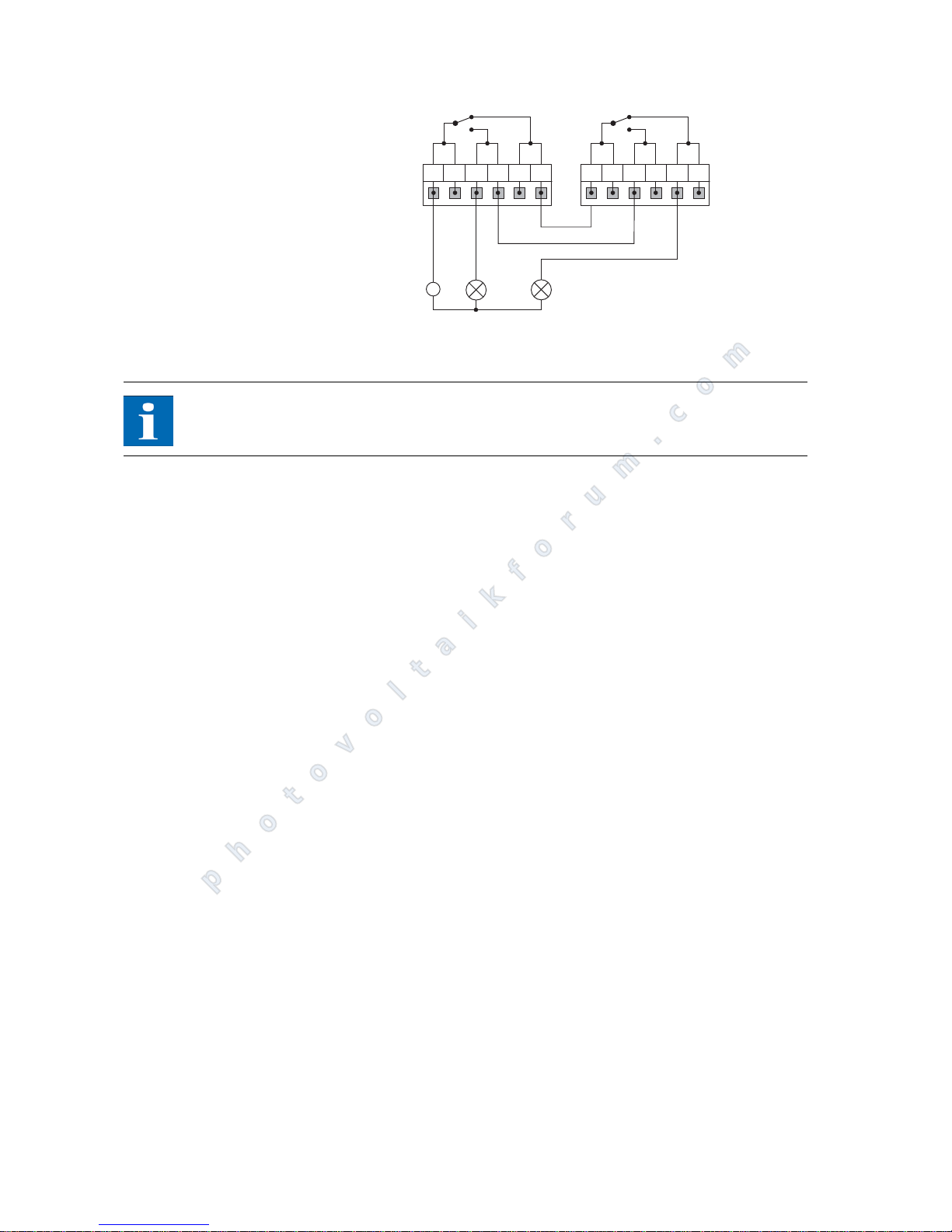
Connecting the alarm relay The Solar Inverter is equipped with a potential-free alarm relay as standard. The
relay is can be designed as a make-contact element or as a break-contact element and is actuated for all malfunctions signalled by the device. This ensures
fast, reliable indication of a possible fault in the PV system on site. For PV systems with several units, the individual relays can be switched in parallel and connected via a common indicator lamp.
The master also signals faults from other units in the CAN network via the alarm
relay. It is therefore sufficient for simple alerting to connect the alarm relay of
the master.
CAUTION
The alarm relay is designed for 230 V / 2 A. Higher outputs/voltages can result
in the relay being destroyed. The connected signalling unit must be fused separately. The terminals are intended for a cable cross-section of 0.2 mm
2
to 1.5
mm2. When dimensioning the cross-section, also take the current consumption
of the connected signalling unit into account.
Wiring diagram for a single unit
Wiring diagram for several units
Assignment of sensor connection
Pin assignment
Plug sensor
Sensor connection designation Connection designati-
on
Solar Inverter
Pin 1 Positive-signal temperature Temp
Pin 2 Positive signal
Irradiance
Solar
Pin 3 Reference earth V-
Pin 4 Positive connection
+5 V supply
V+
~
12
NO
NO
NC
NC
C
C
photovoltaikforum.com
Page 40
Installation
38 PT 30k to PT 33k
1 Indicator lamp, red 2 Indicator lamp, green
NOTE
The Solar Inverter is supplied by the L1 mains phase. If L1 fails, the alarm relay
cannot respond, despite the fact that there is a fault.
~
12
NO
NO
NC
NC
C
C
NO
NO
NC
NC
C
C
photovoltaikforum.com
Page 41
Commissioning
PT 30k to PT 33k 39
5 Commissioning
5.1 Connecting and disconnecting the unit
CAUTION
Ensure proper mechanical and electrical installation before commissioning
the unit.
Check the cables to ensure that they are in sound condition.
Always disconnect the mains connection first by switching off the correspon-
ding mains fuse and before disconnecting the solar generator side by opening the DC load break switch.
NOTE
The Solar Inverter is supplied from the mains. The Solar Inverter switches on automatically when sufficient solar generator output is available. Corresponding
switch-on and switch-off thresholds have been defined for this purpose.
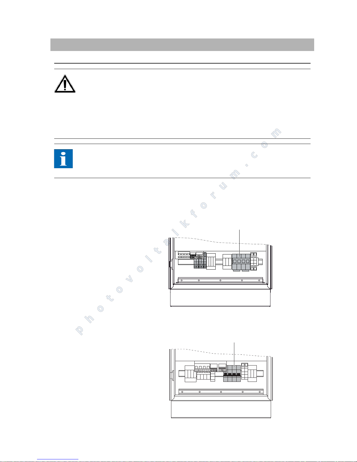
Connecting 1. Establish the grid connection via the external circuit breaker.
2. Switch on the solar generator voltage by closing the DC load break switch
(switching position 1). The Solar Inverter starts operating when the input
voltage level is adequate.
Diagram: IP 42, IP 54 variants
1 DC load break switch
Diagram: IP 5
5/Outdoor variant
L3 L2 L1 N PE
1
1
photovoltaikforum.com
Page 42
Commissioning
40 PT 30k to PT 33k
1 DC load break switch
The operating LED lights up in accordance with the operating state.
The commissioning menu opens when the unit is connected for the first
time.
Switching off 1. Open the grid connection by switching off the circuit breaker.
2. Disconnect the solar generator side by opening the DC load break switch
(switch position 0).
5.2 Commissioning
The commissioning menu comes up automatically when the unit is connected
for the first time. It helps you make the standard settings.
NOTE
For a better understanding of keyboard operation, please also see the chapter
Operation.
The procedure for commissioning the system as a
single unit
and as a master and slaves with several networked units
is described in detail below.
Please note:
NOTE
Once the system has been commissioned, the country can no longer be changed
via the menu. To change the country retrospectively, please contact the Technical Hotline on Tel +49 (0)7531 99677 77-577.
Commissioning single unit
System with one inverter
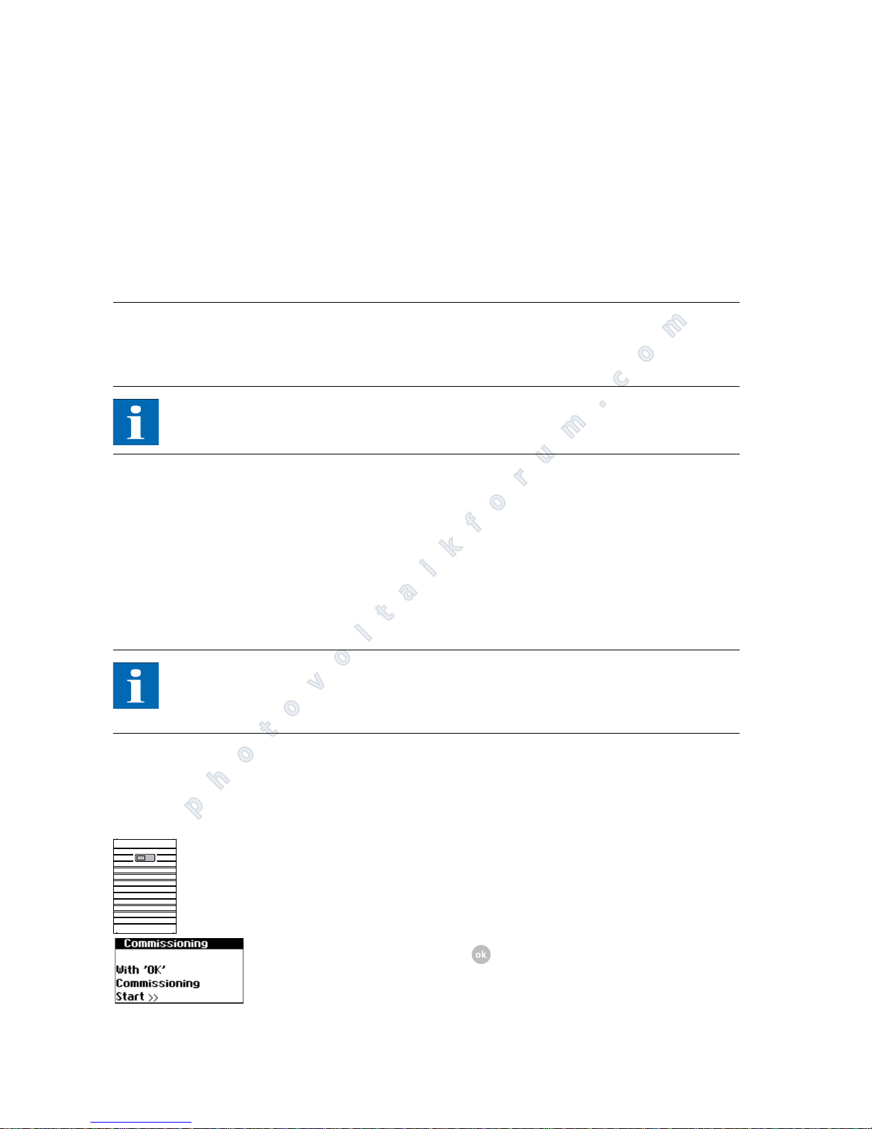
1. During initial start-up the following appears on the display:
Begin commissioning with .
Single device
photovoltaikforum.com
Page 43
Commissioning
PT 30k to PT 33k 41
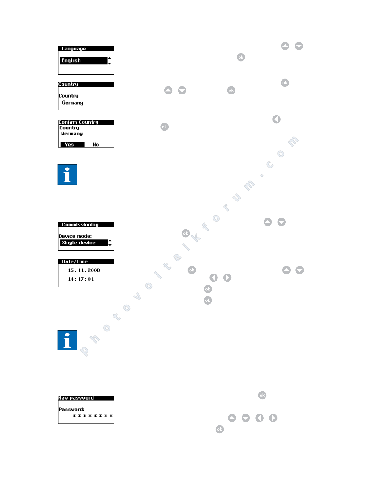
2. To do this, select the language in selection menu with / .
Confirm the selected language with .
3. In the selection menu, switch to the editing mode with , set the country
of use / and select with .
4. If the selected country of use is correct, select with "Yes" and confirm
with .
Your unit is now set up for use on a low voltage grid. The relevant standards
apply!
NOTE
The Solar Inverter only starts feeding current into the grid once the country has
been selected. When installed in Germany, the unit feeds according to the Low
Voltage Directive. The configuration based on the Medium Voltage Directive
can be found in a separate document.
5. Select "Single unit" in the selection menu with / .
Confirm with .
6. Set the date and time.
Select date with . Change the selected number with / and jump
to the next number with / .
Confirm the date with and set the time accordingly.
Confirm the time with .
NOTE
Please note that time settings should only be made with caution, as they directly
affect data logging. For example, if you set the time back by 1 hour, then the
existing data will be overwritten. Check the time during the maintenance intervals regularly for proper functioning and adjust the time at least 1x year if necessary.
7. Setting a password. Select the password with . The default password is:
******** (8 asterisks)
A new password can be set with / / / as an option.
Confirm the password with .
photovoltaikforum.com
Page 44
Commissioning
42 PT 30k to PT 33k
NOTE
Please note:
Only digits between 0 – 9 and letters between a – z and A – Z are permitted.
The password always has 8 characters. If the password you entered has less than
8 characters, the remaining characters are filled with "*".
Example:
Your password is "Solar". This password has 5 characters. The system automatically appends three "*", so that the password becomes "Solar***".
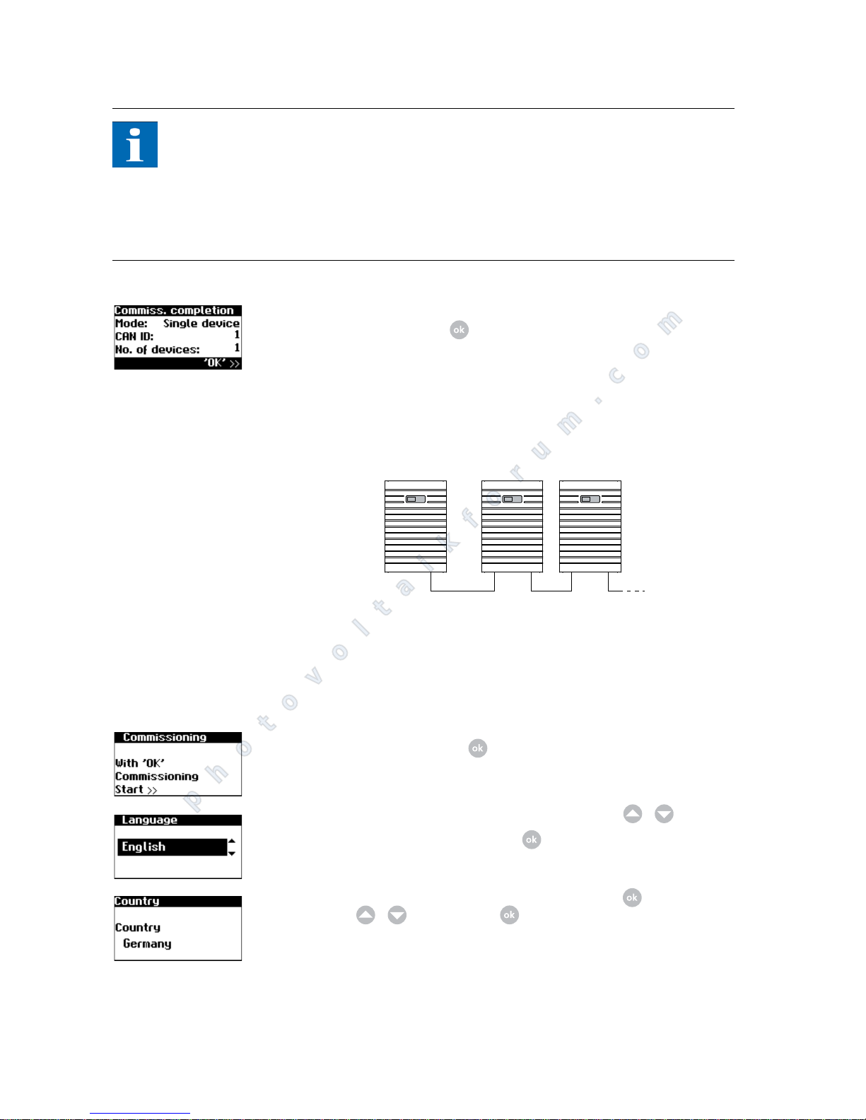
8. Completion of commissioning
Confirm overview with .
Commissioning several networked units
System with several units
Before commissioning, all units must be interconnected via the CAN bus interface. See the chapter on networking Solar Inverter via CAN bus.
Switch on all units following installation. Start commissioning with the unit selected as the master.
Commissioning master
1. During initial start-up the following appears on the display:
Begin commissioning with .
2. To do this, select the language in selection menu with / .
Confirm the selected language with .
3. In the selection menu, switch to the editing mode with , set the country
of use / and select with .
Hauptgerät Nebengeräte
photovoltaikforum.com
Page 45
Commissioning
PT 30k to PT 33k 43
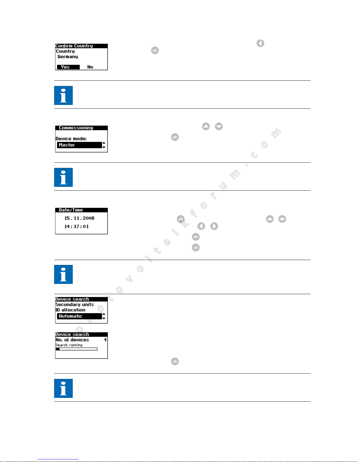
4. If the selected country of use is correct, select with "Yes" and confirm
with .
Your unit is now set up for use on a low voltage grid. The relevant standards
apply!
NOTE
The Solar Inverter only starts feeding current into the grid once the country has
been selected.
5. Select "Master" entry with / .
Confirm with .
NOTE
The other units in the CAN network are automatically configured as slaves.
6. Set the date and time centrally for all connected units.
Select date with . Change the selected number with / and jump
to the next number with / .
Confirm the date with and set the time accordingly.
Confirm the time with .
NOTE
Please note that time settings should only be made with caution, as they directly
affect data logging. For example, if you set the time back by 1 hour, then the
existing data will be overwritten.
7. Automatic or manual device search
The IDs for the slaves can be allocated automatically or manually.
8. CAN network list is set up.
If the search is set to manual, the IDs must be confirmed at each slave before
commissioning of the master is continued.
Confirm with .
NOTE
Depending on the side of the network, it may take a moment until the master
has found all slaves and added them to the list.
photovoltaikforum.com
Page 46
Commissioning
44 PT 30k to PT 33k
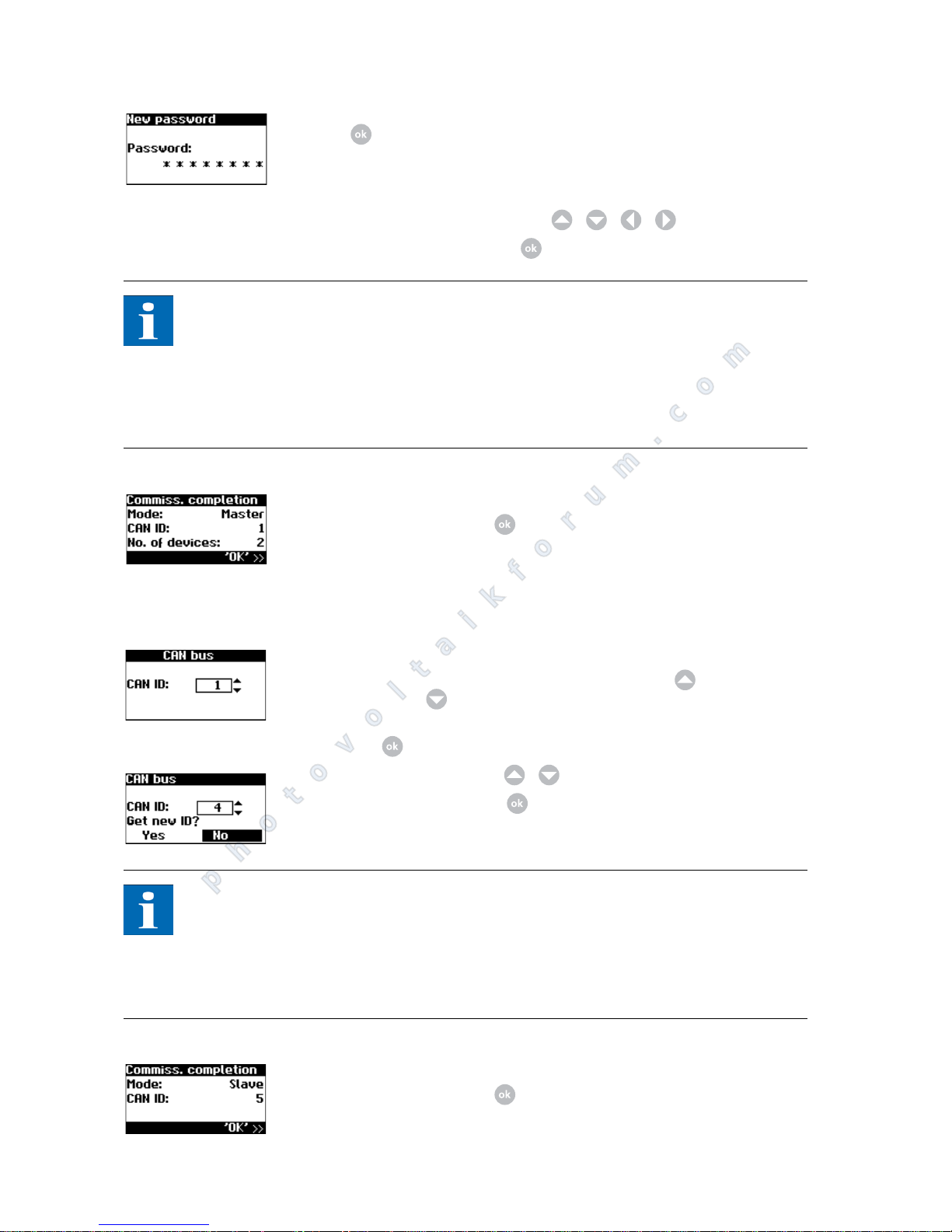
9. Set password centrally for all connected units. Select the password with
.
The default password is:
******** (8 asterisks)
A new password can be set with / / / as an option.
Confirm the password with .
NOTE
Please note:
Only digits between 0 – 9 and letters between a – z and A – Z are permitted.
The password always has 8 characters. If the password you entered has less than
8 characters, the remaining characters are filled with "*".
Example:
Your password is "Solar". This password has 5 characters. The system automatically appends three "*", so that the password becomes "Solar***".
10. Completion of commissioning
Confirm overview with .
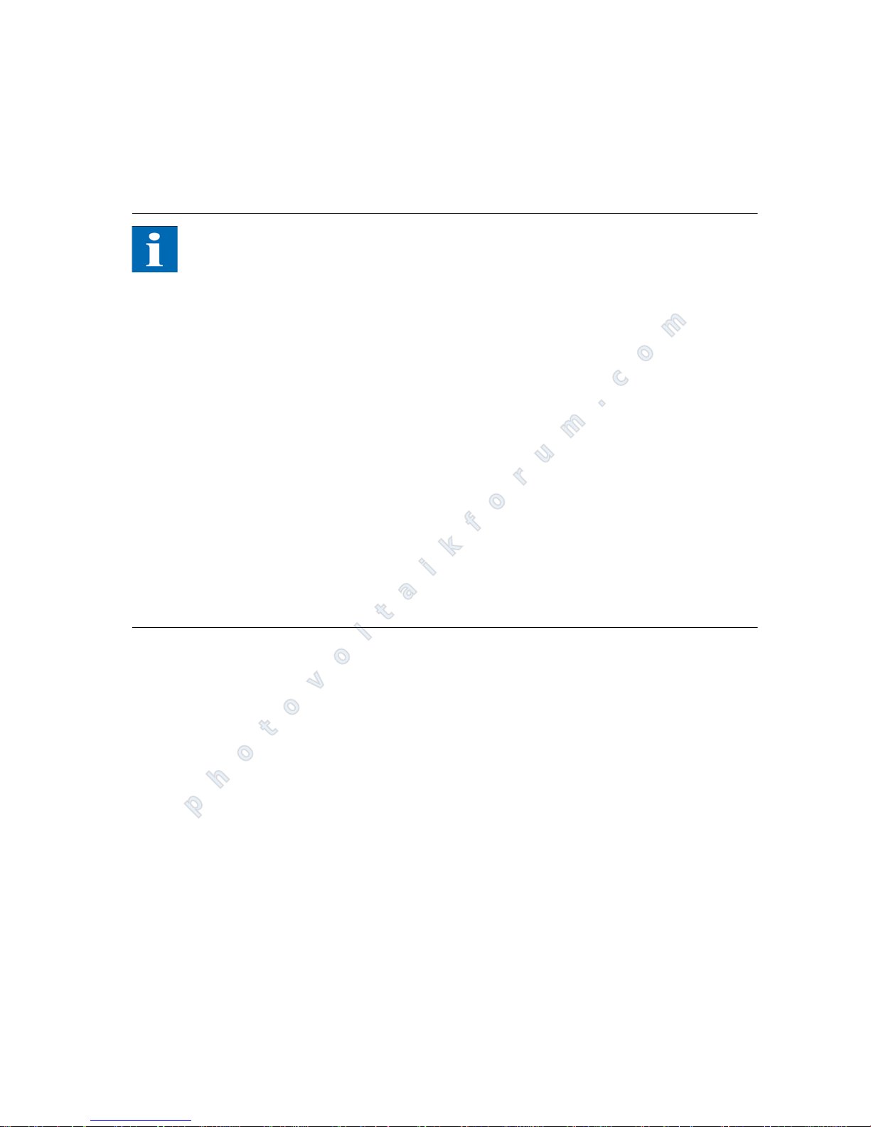
Commissioning slaves After a master has been defined, the display for requesting the CAN-ID is auto-
matically shown on the display on each slave in a manual device search.
1. Request CAN ID (this step is only necessary for manual device searches)
Request the next higher free ID from the master with or the next lower
free ID with .
The master assigns a free ID to the slave. Confirm the ID within 5 seconds
with .
Request further IDs with / .
Confirm the CAN ID with within 5 seconds.
NOTE
The data for the slaves can be assigned in the Sunways browser and in the menu
of the master based on the IDs.
The CAN-ID 1 is automatically assigned to the master. This means the slaves can
be assigned IDs from 2 to 99.
Commissioning cannot be continued until after an ID has been requested from
the master.
2. Completion of commissioning
Confirm overview with .
3. Commissioning of all other slaves as described above
photovoltaikforum.com
Page 47
Commissioning
PT 30k to PT 33k 45
Later commissioning If you add new units or replace existing ones in your solar system, then you can
display the unit list in the display on the master under Settings - Network - CAN
bus. The new unit can then be put into operation in accordance with the description for commissioning slaves.
NOTE
Configuration of grid security management
The inverter has grid management functions in accordance with the following
guidelines:
Technical directive "Power generating facilities using medium-voltage grids"
from the German Energy and Water Association (BDEW).
VDE code of practice "Power generation facilities using low-voltage grids"
These functions can be configured via the Sunways browser on your computer.
The inverter must be connected to the network in order to configure these functions. A device-specific password is required for access to the grid security management configuration pages. This can be obtained on request from the
technical hotline. To do this you must quote the serial number of the inverter
which has been configured as the master.
1. Remotely controlled output reduction
2. Provision of reactive power in normal operation
3. Grid support mode: Limitation of active power at overfrequency
4. Grid support mode: Fault Ride Through (FRT) when mains faults occur – supply of reactive current (short circuit current) to actively support voltage when
there is a voltage drop at the feed point.
photovoltaikforum.com
Page 48

Commissioning
46 PT 30k to PT 33k
photovoltaikforum.com
Page 49
Operation
PT 30k to PT 33k 47
6 Operation
6.1 General information
Operating elements
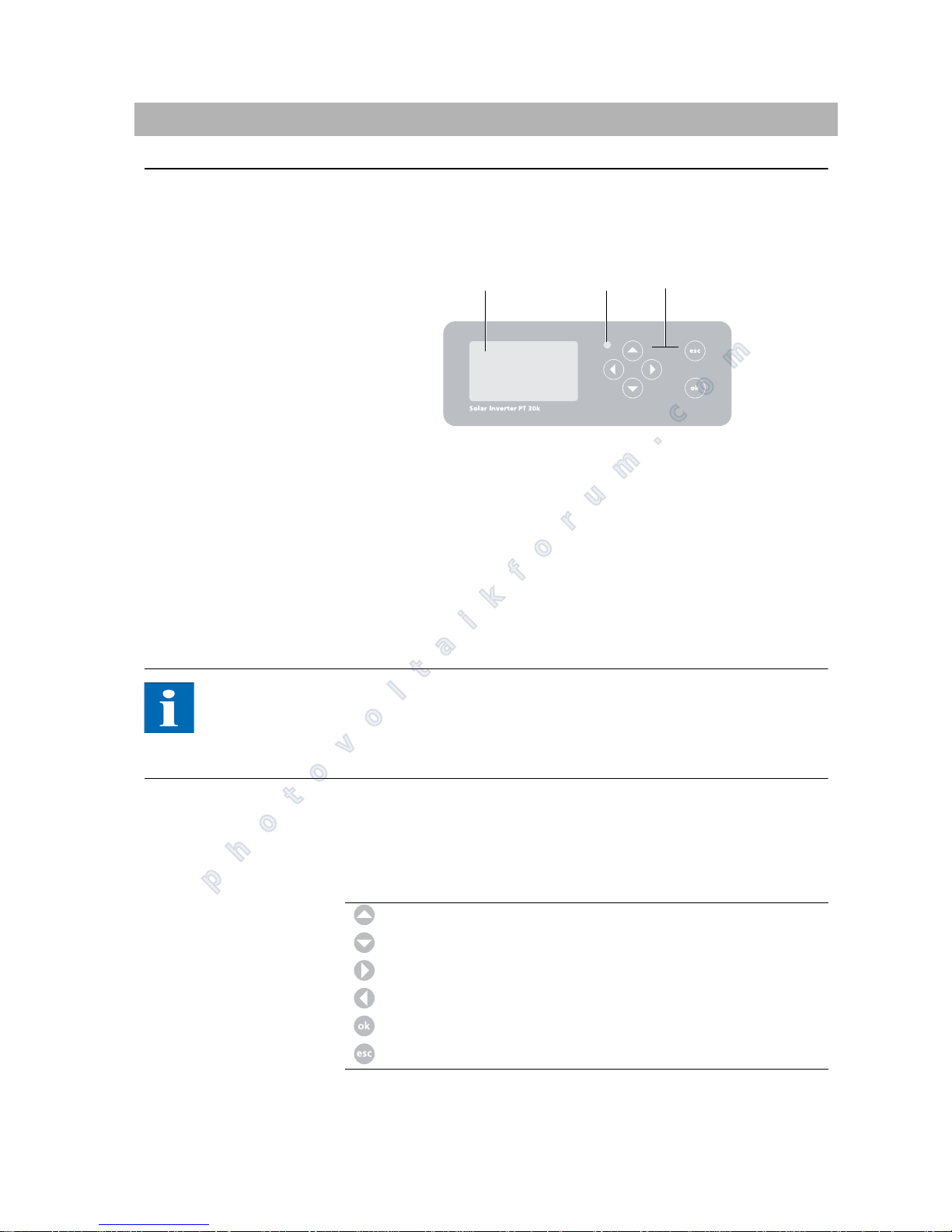
Operating field The unit is operated via the control panel at the front.
1 LCD display (lighted)
2 Operating LED
3Keyboard
LCD display A graphics-capable, monochrome dot matrix display is integrated in the opera-
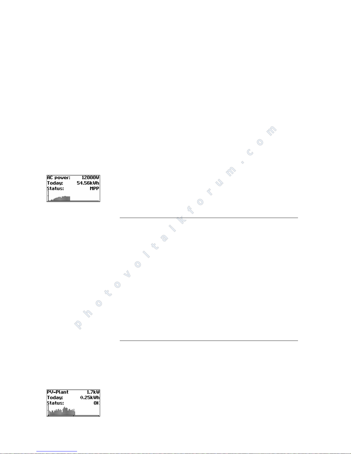
ting field. In standard mode the momentary output, daily yield and status are
displayed. The bar graph shows the energy feed-in of the current day.
Press any key to activate the display lighting.
If no key is pressed for approx. 1 minute, the display lighting goes out.
NOTE
Important!
The LCD display is not a calibrated measuring device. A deviation of several percent is inherent in the system. Exact accounting of the data with the power supply company requires a calibrated meter.
Keyboard The keyboard can be used to navigate in the menu, edit text fields, select entries
from lists and enter numbers consecutively and digit by digit. User entries can
only be made if the value to be changed is selected. The cursor changes visibly
in the editing mode and indicates the digit to be changed.
Operating LED The combined red/green LED indicates the status of the PT 30k to PT 33k:
LED off
123
key Scroll up
key Scroll down
key Select menu item
key Back one menu level
key Select a menu item and confirm your entry
key Quit
photovoltaikforum.com
Page 50
Operation
48 PT 30k to PT 33k
Solar Inverter is not active (night mode)
LED green, continuously lit
Solar Inverter is active and feeds into the grid (MPP mode)
LED green, flashing
Solar Inverter is active and feeds into the grid, although with current, output
or temperature limitation
LED red, continuously lit
a fault has occurred (malfunction)
LED red, flashing
a warning has been output
Standard screen (single unit) The standard screen is always shown when no keyboard entry is made for more
than 1 minute. It can also be called up manually with the menu item "Solar Inverter – Instantaneous Values".
The standard screen shows the most important data at a glance. In the first line
you see the momentary feed-in power. In the second line the fed-in energy for
the day is shown.
The status signals the unit status with the following messages:
The graphic in the lower section of the screen shows the energy fed in for the
day as a bar graph. The current period is shown as a flashing bar, as it is still increasing.
Standard screen (system) You can view the system data for a CAN-networked system with this screen.
Next to the total current system output, you also see the energy yield of your
solar system and any status messages of all connected units. These are provided
with the inverter number. An "M" means that the error has occurred on the
master.
MPP Feeding in MPP mode
AC curr. lim. Feeding with AC current limitation
DC curr. lim. Feeding with DC current limitation
Temp. lim. Feeding with temperature limitation
Output lim. Feeding with output limitation
Feed. Feeding
Warning A warning has been output
Error An error has occurred
Night Night mode
Start Device initialisation phase
COM-Upd. The communication software is being updated
DSP-Upd. The control software is being updated
photovoltaikforum.com
Page 51
Operation
PT 30k to PT 33k 49
NOTE
The various functions are accessed via the menu. The main menu is opened
from the standard screen by pressing twice.
You can return to the standard screen at any time by pressing and holding
the key.
If a status message is shown you can open the error list directly with .
You can access other instantaneous values from the standard screen with
and .
Access rights Operation of the unit is divided into various password-protected sections.
The password has 8 places.
The password can be entered in the menu item "Settings – Login".
NOTE
If no entry is made with the keyboard after entering the password, it is necessary to re-enter the password after approximately 5 minutes.
Customer area The customer password must be entered to access this area. All settings required
for installation and commissioning of the unit are available.
NOTE
The password for the customer area is:
********
The password is preset and is directly confirmed with .
As an option, you can assign a personal password in the Commissioning me-
nu. Only digits between 0 – 9 and letters between a – z and
A – Z are permitted.
The password always has 8 characters. If the password you entered has less
than 8 characters, the remaining characters are filled with "*".
Example:
Your password is "Solar". This password has 5 characters. The system automatically appends three "*", so that the password becomes "Solar***".
Installer area In this section, the installer can make special settings on the Solar Inverter which
are only possible after consulting the Technical Hotline. Request a device-specific password from the Technical Hotline.
Technical Hotline +49 (0) 7531 996 77-577
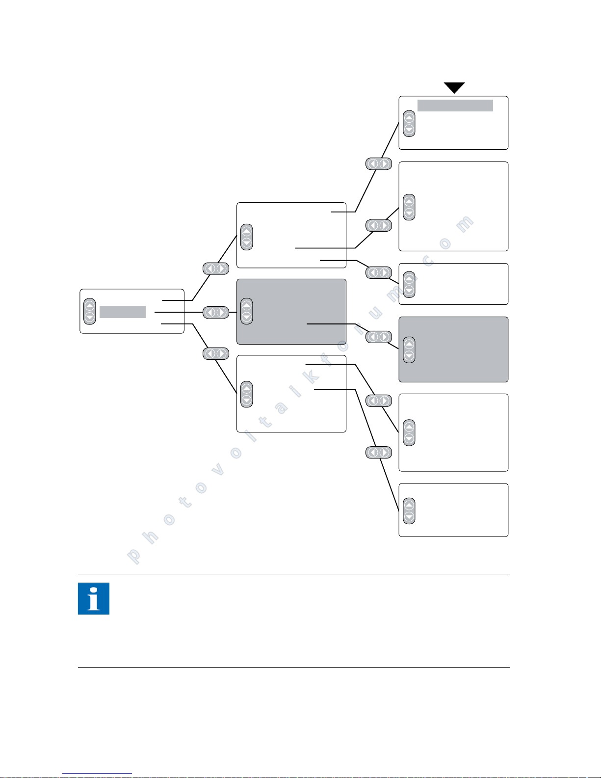
Menu structure The menu provides access to all screens on the Solar Inverter. The menu is ope-
ned by pressing the left arrow key from the standard screen.
photovoltaikforum.com
Page 52
Operation
50 PT 30k to PT 33k
NOTE
The areas highlighted in grey are only available in the master
*) after entering the customer password. Standard password: ******** (= 8
asterisks)
**) this is only shown if the configured country of installation is Italy
Solar Inverter
PV system
Settings
Actual values
Energy yield
Events
History
Information
Actual values
Energy yield
Events
Plant history
System info
General
Login
Network*
Commissioning*
Change country*
Self-testing**
Yield week
Yield 15 days
Yield month
AC power
DC values
AC values
Standard screen
Actual values 1
Actual values 2
Cooling system
Language
LCD contrast
Date/Time*
Receipt time*
Firmware*
Password*
Yield week
Yield 15 days
Yield month
Total power
Max.output
Max.output
Ethernet
CAN bus
Interfaces
RS485 Bus
Firmware
Memory
Mode
START
photovoltaikforum.com
Page 53
Operation
PT 30k to PT 33k 51
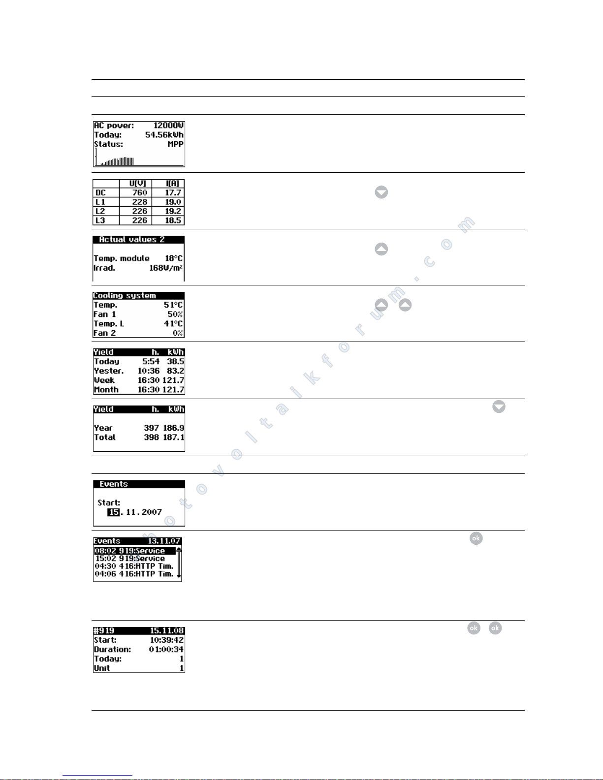
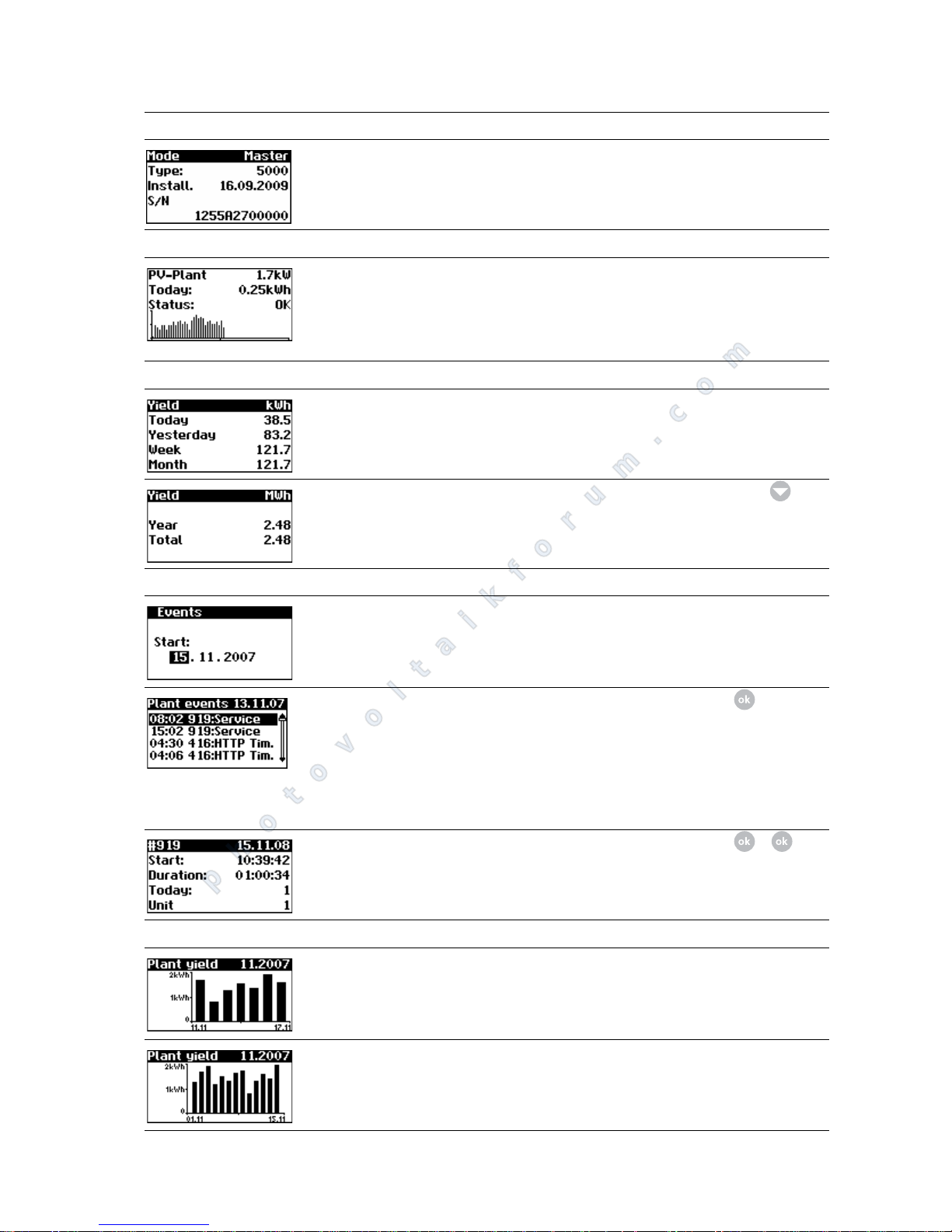
Overview of screen displays
Display Description Calling Menu
Instantaneous Values – Unit
Current feed-in power, daily energy
yield and unit status
MPP: Feeding in MPP mode
The screen appears automatically if no
key is pressed for several minutes.
Solar Inverter – Instantaneous values
Display of voltages and currents from
solar generator and grid
Solar Inverter – Instantaneous values –
Module temperature and irradiance
values (if sensor is connected)
Solar Inverter – Instantaneous values –
Display of heat sink and choke temperature and load of the two fans
Solar Inverter – Instantaneous values –
–
AC yields and operating hours from
today, yesterday, week and month
Solar Inverter – Energy yield
AC yields and operating hours from
year and total value
Solar Inverter – Energy yield –
Events – Unit
Select starting data for event display Solar Inverter – Events
Display event list
The event list shows the last 200 system messages from the start date. The
heading always refers to the selected
event. The CAN comm. message displayed here must not necessarily be
from 07/05/2006, it may be older.
Solar Inverter – Events –
Display event details (error number,
data, starting time, duration and
number of occurrences per day)
Solar Inverter – Events – –
photovoltaikforum.com
Page 54
Operation
52 PT 30k to PT 33k
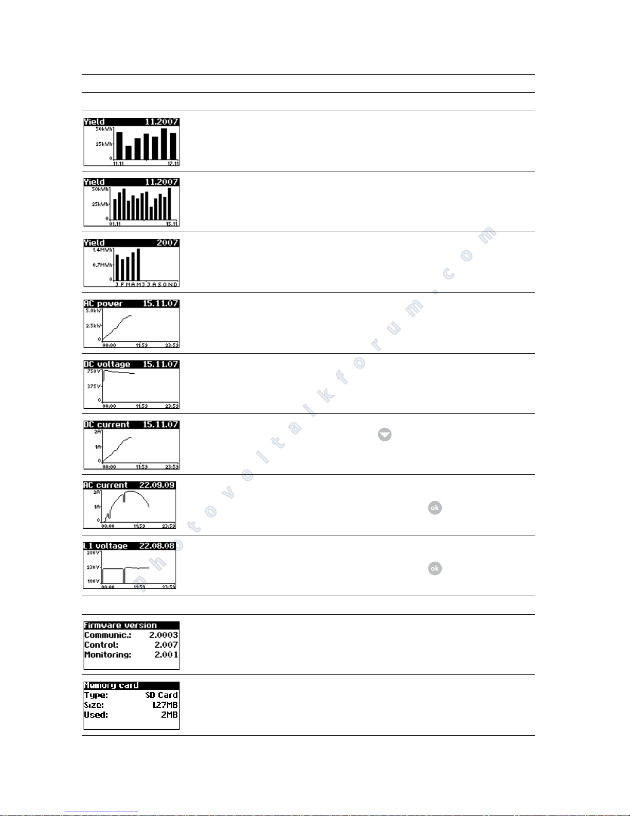
History – Unit
Daily yield for 1 week Solar Inverter – History – Yield for
week
Daily yields for 15 days Solar Inverter – History – Yield for 15
days
Monthly yields Solar Inverter – History – Yield for
month
AC output (5-min. values) Solar Inverter – History – AC output
DC voltage (5-min. values) Solar Inverter – History – DC values
DC current (5-min. values) Solar Inverter – History – DC values–
AC current L1 (5-min. values)
AC current L2 (5-min. values)
AC current L3 (5-min. values)
Solar Inverter – History – AC values
Switching between currents L1, L2
and L3 with
AC voltage L1 (5-min. values)
AC voltage L2 (5-min. values)
AC voltage L3 (5-min. values)
Solar Inverter – History – AC values
Switching between voltages L1, L2
and L3 with
Information – Unit
Firmware Solar Inverter – Information – Firmwa-
re
Memory card Solar Inverter – Information – Memory
Display Description Calling Menu
photovoltaikforum.com
Page 55
Operation
PT 30k to PT 33k 53
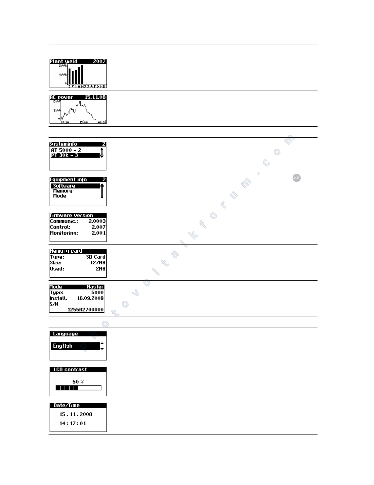
Device mode Solar Inverter – Information – Mode
Instantaneous values – Solar system (display only master)
Current system feed-in power, daily
energy yield and system status
The screen appears on the master automatically when you do not make
any entries with the keyboard for several minutes.
Solar system – Instantaneous values
Yields – Solar system (display only master)
AC system yields and operating hours
from today, yesterday, week and
month
Solar system – Energy yield
AC system yields and operating hours
for year and total value
Solar system – Energy yield –
Events – Solar system (display only master)
Select starting data for system event
display
Solar system – Events
Display event list for entire system
The event list shows the last 200 system messages from the start date. The
heading always refers to the selected
event. The CAN comm. message displayed here must not necessarily be
from 10/05/2007, it may be older.
Solar system – Events –
Display event details (error number,
data, starting time, duration and
number of occurrences per day)
Solar system – Events – –
History – Solar system (display only master)
Solar system daily yield for 1 week Solar system – System history – Yield
for week
Solar system daily yield for 15 days Solar system – System history – Yield
for 15 days
Display Description Calling Menu
photovoltaikforum.com
Page 56
Operation
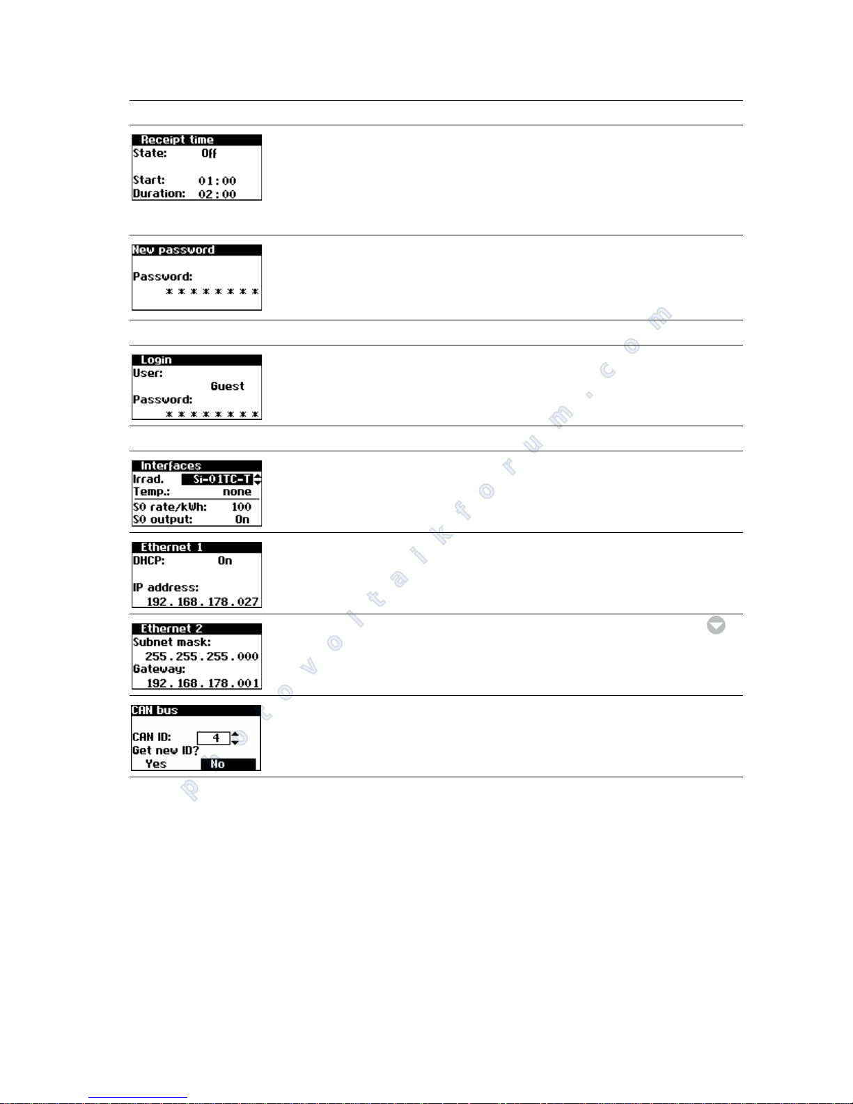
54 PT 30k to PT 33k
Solar system monthly yields Solar system – System history – Yield
for month
Solar system AC output (5-min. values) Solar system – System history – AC out-
put
System info – Solar system (display only master)
Unit list for selecting a unit Solar system – System info
Selection of information Solar system – System info –
Firmware Solar system – System info – Firmware
Memory card Solar system – System info – Memory
Device mode Solar system – System info – Mode
Settings – General
Display language Settings – General – Language
LCD contrast Settings – General – LCD contrast
Set date/time
(only possible with customer password)
Settings – General – Date/Time
Display Description Calling Menu
photovoltaikforum.com
Page 57
Operation
PT 30k to PT 33k 55
Error messages The Solar Inverter indicates faults on the LCD display and saves them in the in-
ternal error memory.
The fault display consists of a number and a short description. Based on the first
number, you can quickly recognise which area the fault has occurred in:
1: Solar generator fault
2: AC grid fault
3: Inverter fault
4: Interface/communication fault
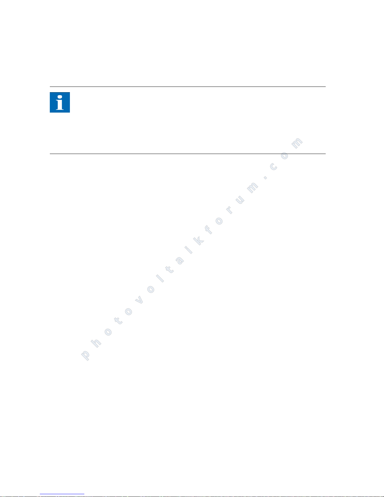
Set receiving time (starting time and
duration in which the unit can also be
addressed in the night mode via the
network).
(only possible with customer password)
Settings – General – Receiving time
Changing the customer password
(only possible with customer password)
Settings – General – Password
Settings – Login
Password entry to access advanced
settings (necessary for commissioning)
Settings – Login
Settings – Network (only possible with customer password)
Setting of the irradiance and temperature sensor and configuration of the
S0 pulse output
Settings – Network – Interfaces
Network settings (Screen 1)
Activate DHCP for automatic IP
address setting or enter IP address manually
Settings – Network – Ethernet
Network settings (Screen 2) Settings – Network – Ethernet –
Have CAN bus ID assigned by the master
Settings – Network – CAN bus
Display Description Calling Menu
photovoltaikforum.com
Page 58
Operation
56 PT 30k to PT 33k
9: Service error
If an error is shown in the standard display, then you can look up the exact error
message in the menu under "Solar Inverter – Events".
NOTE
A restart may be attempted in the event of an error message.
Please note the serial number of the unit and the error number before con-
tacting the Technical Hotline.
The Technical Hotline can be contacted on +49 (0) 7531 996 77-577 between
7.30 am and 6 pm CET during weekdays.
photovoltaikforum.com
Page 59

Operation
PT 30k to PT 33k 57
Display message Description Cause and possible remedies
Solar generator fault
101:U-DC max. Your PT series Solar Inverter is approved
for a maximum open-circuit voltage of
the solar generator of 1000 V. All DC input components are adequately dimensioned with a safety margin. The Solar
Inverter stops feeding if the threshold is
exceeded.
The maximum DC voltage was exceeded.
Check the dimensioning of your PV
generator.
Too many modules are connected in series.
Reduce the number of modules and
re-commission the system.
102:Insulation Before each connection, your Solar Inver-
ter checks the PV system for a possible
earth fault or insulation faults. If this kind
of error is detected, no feed in takes
place. The mode of operation is compliant with DIN V VDE 0126-1-1.
The Solar Inverter has detected an insulation fault in the PV system during startup.
Check your PV system for possible in-
sulation faults (damaged DC cables
etc.).
The measured insulation resistance must
be at least 1000 k.
103:AFI>30 mA
104:AFI>0.3 A
Your Solar Inverter is equipped with an
AC/DC sensitive AFI according to DIN VDE
0126-1-1. The monitoring unit has detected a sudden relative residual current increase of >30 mA or an absolute residual
current of >300 mA.
A sudden residual current increase has occurred during the unit operation.
Check your PV system for possible in-
sulation faults.
105:I-DC max. Your PT series Solar Inverter is approved
for a maximum DC current of 75 A. If the
threshold is exceeded, the Solar Inverter
limits the DC current by moving the operating point.
The maximum solar generator current
permitted for the inverter was reached.
Check that the module interconnec-
tion generates an input voltage of
less than 420 VDC at full load and
rewire the modules according to the
min. DC input voltage of 420 VDC.
AC grid fault
201:UAC1<Min
202:UAC2<Min
203:UAC3<Min
AC undervoltage
Your Solar Inverter continuously monitors the voltage levels for feed phases L1,
L2 and L3. If the voltage falls below the
minimum permissible limit, the Solar Inverter stops feeding and does not start up
again until the voltage value exceeds the
minimum limit value.
Ask your power supply company
(PSC) about grid stability and design.
Ensure that the cross-sections of the
feed lines are adequate, depending
on country-specific standards and
guidelines.
204:UAC1>Max
205:UAC2>Max
206:UAC3>Max
AC overvoltage
Your Solar Inverter continuously monitors the voltage levels for feed phases L1,
L2 and L3. If the maximum permissible limit is exceeded, the Solar Inverter stops
feeding and does not start up again until
the voltage value drops below the maximum permissible limit.
Ask your power supply company
(PSC) about grid stability and design.
E
nsure that the cross-sections of the
feed
lines are adequate, depending
on country-specific standards and
guidelines.
photovoltaikforum.com
Page 60

Operation
58 PT 30k to PT 33k
207:UAC1>10 %
208:UAC2>10%
209:UAC3>10%
AC overvoltage for 10 minutes
Your Solar Inverter continuously monitors the voltage levels for feed phases L1,
L2 and L3. If the permitted limit value is
exceeded for 10 minutes on average, the
Solar Inverter stops feeding and restarts
after approx. 1 minute.
Ask your power supply company
(PSC) about grid stability and design.
Ensure that the cross-sections of the
feed lines are adequate, depending
on country-specific standards and
guidelines.
210:UAC1>10 %
211:UAC2>10%
212:UAC3>10%
(Warnings)
AC overvoltage warning
This warning appears if a voltage which is
too high is measured on a mains phase.
The Solar Inverter switches off if the limit
is exceeded for more than 10 minutes.
Ask your power supply company
(PSC) about grid stability and design.
Ensure that the cross-sections of the
feed lines are adequate, depending
on country-specific standards and
guidelines
213:Frq1<Min
214:Frq2<Min
215:Frq3<Min
216:Frq1>Max
217:Frq2>Max
218:Frq3>Max
Grid frequency
The Solar Inverter continuously monitors
the grid frequency for feed phases L1, L2
and L3. If the value for a phase is outside
the permitted range, the Solar Inverter
stops feeding and does not start up again
until the value is within the tolerance range.
Restart time: approx. 45 s
Ask your power supply company
(PSC) about grid stability and configuration
219:IDC1>Max
220:IDC2>Max
221:IDC3>Max
DC share in AC current
Your Solar Inverter continually monitors
the quality of current that is fed in. If the
maximum DC share in the current fed in is
exceeded, the Solar Inverter stops feeding.
Restart the Solar Inverter.
If the error still occurs, please contact the
technical hotline. The phone number is
provided on the back of the manual.
222:Uexternal External conductor voltage outside tole-
rance range. Invalid phase shift between
L1, L2 and L3.
Ask your power supply company
(PSC) about grid stability and design.
Ensure that the cross-sections of the
feed lines are adequate, depending
on country-specific standards and
guidelines.
223:Surgef. Your Solar Inverter continuously moni-
tors the quality of the AC grid. During
high voltage peaks on the phase feeding
in, the Solar Inverter stops feeding and
attempts a restart.
The Solar Inverter has detected a high
voltage peak on a phase feeding in.
After successful troubleshooting, the
Solar Inverter restarts automatically.
A monitoring phase and a neutral
conductor were interchanged during
connection of the AC side
Inverter fault
Display message Description Cause and possible remedies
photovoltaikforum.com
Page 61

Operation
PT 30k to PT 33k 59
301:HS temp.
302:Choke temp.
303:PCB temp.
(Warnings)
Your Solar Inverter is designed for an ambient temperature of up to +40 C at full
feed-in power. These warnings refer to violations of the temperature threshold for
the heat sink (HS), choke or PCB.
The feed-in power is reduced linearly in
order to prevent further temperature increase.
The maximum permissible ambient temperature has been exceeded.
The installation location may be un-
suitable. Please try and find an alternative installation location or
improve the ventilation of the installation space.
The air circulation requirement was not
taken into account during installation.
Clean the Solar Inverter if dirt obst-
ructs cooling.
Follow the installation instructions in
the manual.
304:Mains rel. The PT series Solar Inverter checks the
operation of the mains relay whenever it
is switched on An error was detected during this check.
Restart the Solar Inverter.
If the error still occurs, please contact the
technical hotline. The phone number is
provided on the back of the manual.
305:HS overtemp.
306:Choke overtemp.
307:PCB overtemp.
These error messages refer to violations
of the temperature threshold for the heat
sink (HS), choke or PCB. Feed is stopped.
The Solar Inverter automatically switches
back on again once the temperature at
the corresponding measuring point has
dropped again.
The maximum permissible ambient temperature has been exceeded.
The installation location may be un-
suitable. Please try and find an alternative installation location or
improve the ventilation of the installation space.
The air circulation requirement was not
taken into account during installation.
Clean the Solar Inverter if dirt obst-
ructs cooling.
Follow the installation instructions in
the manual.
Interface/communication fault
401:SD Card The Solar Inverter cannot fi nd an SD card. Restart the Solar Inverter.
If the error still occurs, please contact the
technical hotline. The phone number is
provided on the back of the manual.
402:SD Card The SD card is write-protected. Restart the Solar Inverter.
If the error still occurs, please contact the
Technical Hotline. The phone number is
provided on the back of the manual.
403:CAN User Communication error with CAN user. Check whether an error has occurred
in the CAN secondary unit. Restart
the secondary unit and main unit if
necessary.
Display message Description Cause and possible remedies
photovoltaikforum.com
Page 62

Operation
60 PT 30k to PT 33k
404:CAN Bus CAN bus not in operation. No communication is possible via the CAN
bus.
Check the bus cables and termination
resistors.
Check whether the maximum line
lengths are within the permitted limits.
Check whether bus cables were ins-
talled parallel to power cables. Disconnect bus lines and power cables if
necessary.
405:CAN User CAN user does not respond. Check whether an error has occurred
in the CAN secondary unit. Restart
the secondary unit and main unit if
necessary.
406:Solar
407:Temp.
(Warning)
No sensor found on sensor channel 1 (solar) or 2 (temperature).
If a sensor is connected at Solar or Temp:
Check the sensor connection.
If no sensor is connected:
Check the sensor input configuration
via the LCD display or the Sunways
browser.
408:CAN comm.
(Warning)
Communication malfunctions occur repeatedly on the CAN bus.
A malfunction occurs in the data transmission on the CAN bus. However, a data
exchange continues to be possible.
Check whether all bus line connectors
and terminating resistors are mounted properly.
Check whether bus cables were ins-
talled parallel to power cables. Disconnect bus lines and power cables if
necessary.
409:CAN Cfg.
(Warning)
The CAN bus is in configuration mode. No
measured values are transferred.
At least one unit is in the menu item "Settings – Network – CAN bus".
Close this menu in all units.
410:SMTP Ser.
(Warning)
SMTP server cannot be reached An error occurred during e-mail delivery.
Re-attempting e-mail delivery.
If the fault keeps recurring, check the
e-mail settings via the Sunways browser
411:SMTP Soc.
(Warning)
SMTP no socket available
412:SMTP com
(Warning)
SMTP faulty communication with server
Display message Description Cause and possible remedies
photovoltaikforum.com
Page 63

Operation
PT 30k to PT 33k 61
413:DNS failed
(Warning)
DNS has failed Communication fault between the integ-
rated web server and an Internet browser
in conjunction with the Sunways browser.
These warnings are non-critical and can
be ignored if they only occur occasionally.
These warnings have no effect on the
energy production of the inverter.
414:HTTP Con.
(Warning)
HTTP client connection has failed
415:HTTP Aut.
(Warning)
HTTP client authorisation has failed
416:HTTP Tim.
(Warning)
HTTP client timeout
417:HTTP Soc.
(Warning)
HTTP client no socket available
418:HTTP Soc.
(Warning)
HTTP client error with socket
419:HTTP Met.
(Warning)
HTTP client incorrect method
420:HTTP Pro.
(Warning)
HTTP client error with protocol
421:HTTP Wri.
(Warning)
HTTP client write error
422:HTTP Rea.
(Warning)
HTTP client read error
423:CAN Init
(Warning)
CAN initialisation error CAN bus initialisation fault during device
startup.
Restart the Solar Inverter.
If the error still occurs, please contact the
Technical Hotline. The phone number is
provided on the back of the manual.
424:NTP failed Time synchronisation with the NTP server
has failed.
Firewall port 123 is blocked.
Select an alternative time server
425:Min. rest.
426:Day rest.
427:Mon. rest.
428:Year rest.
429:Tot. rest.
430:Sys. rest.
431:File rest.
If there is an error in the SD file system,
the data logger files will be reset. This
means that data previously present will
be lost. (Warnings)
Write errors are very rare and can have
various causes.
No remedy on the part of the user is necessary.
432:PSC 0%
433:PSC 10 %
434:PSC 20 %
435:PSC 30 %
436:PSC 40 %
437:PSC 50 %
438:PSC 60 %
439:PSC 70 %
440:PSC 80 %
441:PSC 90 %
442:PSC 100 %
Output limitation set by PSC as a percentage value of rated capacity (warnings)
The PSC may temporarily reduce system
output in accordance with guidelines.
Display message Description Cause and possible remedies
photovoltaikforum.com
Page 64
Operation
62 PT 30k to PT 33k
6.2 System monitoring
General information The basis for the system monitoring is the data logger integrated in the Solar
Inverter PT series. The Solar Inverter of the PT series series offer a wide range of
monitoring options for your solar system:
The Sunways browser can display instantaneous values, stored operating
data and settings.
With active alerting, information about faults in the solar system can be sent
to a selected recipient via e-mail.
Via the Sunways portal connection the PT series Solar Inverter can send the
operating data of your solar system to the Sunways portal on a daily basis without additional hardware. In this way, you can monitor your yields via the
Internet from wherever you are.
Three networking options are available for access to the system monitoring
function:
Direct connection via an Ethernet cable (see section Direct Ethernet connec-
tion) or internal network (see section Connection via an existing Ethernet
network)
NOTE
With a direct connection or an internal network without gateway to the Internet, the Solar Inverter is unable to send e-mails. Portal connection and active
alerting is therefore not possible.
Connection via Internet, e.g. via a DSL connection for the unit (see section
Remote access via a DSL router)
Connection via a Sunways modem (see section Connection via a Sunways mo-
dem)
Integrated data logger The integrated data logger stores the operating data of your solar system. In ad-
dition to 5-minute mean values, energy yields are also stored as 5-minute, daily,
weekly, monthly and annual values. In addition up to 200 error/warning messages can be stored. Each data record contains the data and time. The data logger
443:PSC M1
444:PSC M2
445:PSC M3
446:PSC M4
447:PSC M5
Mode change by PSC CosPhi = 1
Mode change by PSC fixed CosPhi
Mode change by PSC fixed reactive power
Mode change by PSC CosPhi(P)
Mode change by PSC Q(U)
The PSC may change the operating mode
in accordance with guidelines.
Service fault
9xx:Service fault
9xx: Service warning
A service error has occurred. Disconnect the Solar Inverter from
the grid and from the solar generator
and reconnect it.
If the error occurs again, please contact
the Technical Hotline. The phone number
is provided on the back of the manual.
Display message Description Cause and possible remedies
photovoltaikforum.com
Page 65

Operation
PT 30k to PT 33k 63
is designed as a circulating memory, i.e. the respective oldest data are overwritten with new data.
Operating data (5-min. average values)
Energy Yields
Status messages
Direct Ethernet connection The Solar Inverter are equipped with an Ethernet interface as standard for sys-
tem monitoring and configuration with a PC.
Connect your PC and the Solar Inverter using the Ethernet cable provided.
X-patch cables can also be used.
The PC is connected to the master as standard. Basically all Solar Inverter – including Solar Inverter configured as secondary units or single units – feature their
own web server, so that a connection with any device can be established.
Number Value
2000 DC current
2000 DC voltage
2000 AC current L1
2000 AC current L2
2000 AC current L3
2000 AC voltage L1
2000 AC voltage L2
2000 AC voltage L3
2000 AC output
2000 Unit temperature
2000 Module irradiance (opt.)
2000 Module temperature (opt.)
Number Value
2000 5-minute yield
800 Daily yield
800 Weekly yield
250 Monthly yield
20 Annual yield
Number Value
200 Status changes
photovoltaikforum.com
Page 66
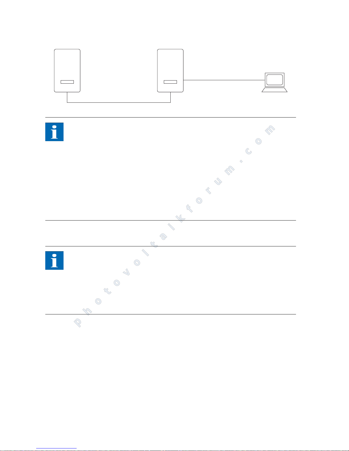
Operation
64 PT 30k to PT 33k
NOTE
To always find the suitable configuration for installation and commissioning
on the PC, we recommend the use of a second network card (e.g. PCI bus,
PCMCIA) which you can configure to match the default setting of the PT 30k
to PT 33k.
The PC and the Solar Inverter must have matching IP addresses and net
masks. The network settings can be adjusted either directly on the Solar Inverter via the LCD display or on your PC. Example: Solar Inverter with the IP:
192.168.30.50, PC with the IP: 192.168.30.51, subnet mask (PT 30k to PT 33k
& PC): 255.255.255.0
If two network cards are used, the IP addresses must be in separate subnets,
e.g. 192.168.30.XXX and 192.168.40.XXX.
Network settings on the Solar
Inverter
NOTE
The Solar Inverter is supplied with the following preset IP address:
192.168.30.50
In the default setting, the Solar Inverter does not support DHCP (Dynamic
Host Configuration Protocol). Therefore, the IP address is not assigned automatically. It is possible to activate the DHCP protocol via the Settings menu.
IP addresses may not be assigned twice within the network!
If required, you can assign your own IP address for the Solar Inverter via the Settings menu.
1. Open the menu Settings – Login.
2. Enter the default password (********, i.e. 8 asterisks) or the password you
have assigned.
PC
MasterSlave
INVERTER
INVERTER
Max. total CAN bus length:
500 m
Max. Ethernet connection:
100 m
photovoltaikforum.com
Page 67
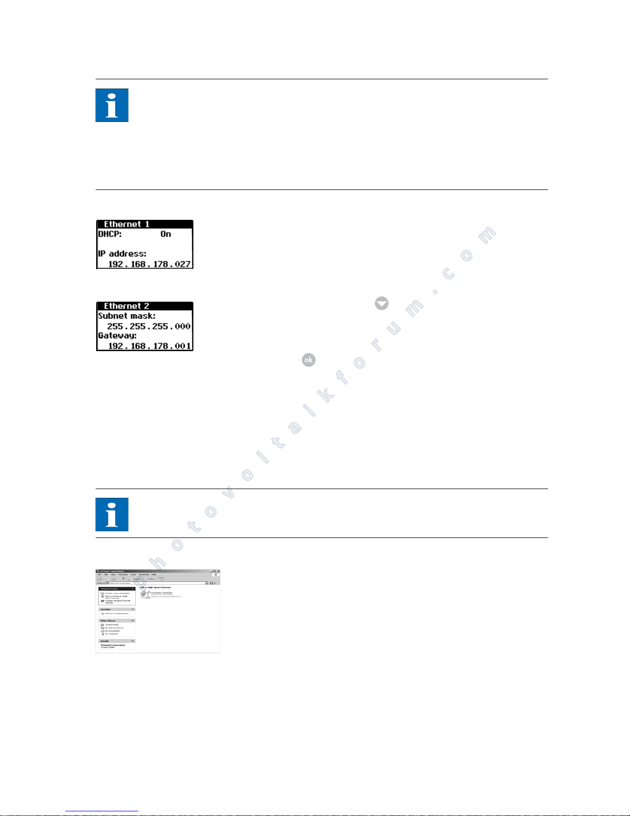
Operation
PT 30k to PT 33k 65
NOTE
Please note:
Only digits between 0 – 9 and letters between a – z and A – Z are permitted.
The password always has 8 characters. If the password you entered has less than
8 characters, the remaining characters are filled with "*".
Example:
Your password is "Solar". This password has 5 characters. The system automatically appends three "*", so that the password becomes "Solar***".
3. Open the menu "Settings – Network – Ethernet".
4. Enter an IP address PC matching your PC. I.e. the first three number blocks
must be identical, the last number block different.
Example:
If your PC has the IP address 192.168.1.1, assign the IP address 192.168.1.2
to the Solar Inverter
5. Call up additional settings with .
6. Enter the subnet mask 255.255.255.0 here.
7. Enter the IP address of your PC in the gateway.
8. Confirm with .
After the connection is established, you can start the Sunways browser by entering the IP address of the solar inverter in the address line of your web browser.
PT 30k to PT 33k
Network settings on PC To enable your PC to communicate with the Solar Inverter, you must assign net-
work settings. The procedure differs slightly depending on the operating system. A configuration example under Windows
®
XP is shown below.
NOTE
IP addresses may not be assigned twice within the network!
1. Select Start - Settings.
2. Select Network Connections.
photovoltaikforum.com
Page 68
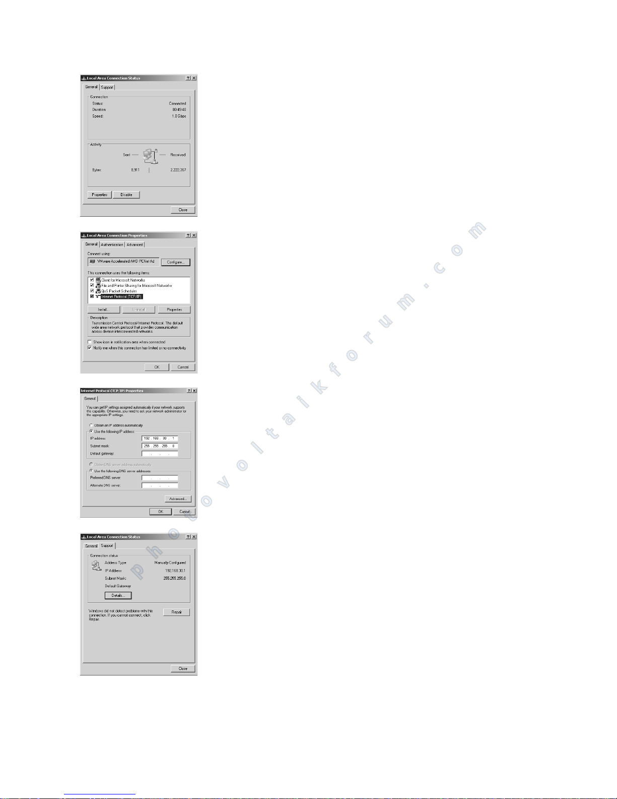
Operation
66 PT 30k to PT 33k
3. Double-click on the LAN connection via which you are connected to the Solar Inverter.
4. Click in the Status window on "Properties".
5. Mark Internet Protocol (TCP/IP) and click on "Properties" again.
6. Now assign an unused IP address 192.168.30.XXX and enter the subnet
mask 255.255.255.0.
7. Click on OK to confirm your entries.
8. In the "Status" menu item, you can check the correctness of your entries
and the status of your connection.
photovoltaikforum.com
Page 69
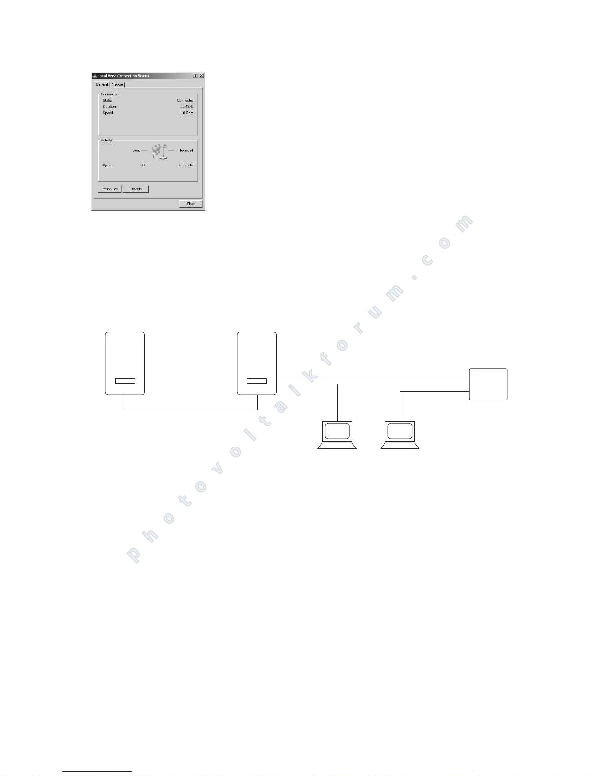
Operation
PT 30k to PT 33k 67
After the connection is established, you can start the Sunways browser by entering the IP address of the PT series in the address line of your web browser.
For more complex network configurations, please contact your network administrator.
Connection via an existing
Ethernet network
You can integrate the PT series Solar Inverter directly in an existing home or
company network as a network device.
Connect your PC and the Solar Inverter with a CAT 5 Ethernet patch cable.
The master is connected to the network as standard.
With DHCP If a DHCP server is present in your network, you can activate DHCP on the Solar
Inverter. In this case, the Solar Inverter obtains the network settings automatically. You can display the assigned IP address via the LCD display (menu Settings
– Network – Ethernet).
Without DHCP If there is no DHCP server in your network, you must set an unused IP address
on the Solar Inverter (see section Solar Inverter network settings).
Ask your network administrator for the necessary settings for IP address, net
mask and gateway.
After the connection is established, you can start the Sunways browser by entering the IP address of the Solar Inverter in the address line of your web browser.
Remote access via a DSL router If a DSL connection or a network with Internet access is available, you can make
the Solar Inverter accessible via the Internet.
Requirements:
Your DSL router supports static IP address services such as www.dyndns.org.
Your router supports port forwarding.
PC
PC
Hub
Switch
Router
INVERTER
INVERTER
Master
Slave
Max. total CAN bus length:
500 m
Max. Ethernet connection:
100 m
photovoltaikforum.com
Page 70
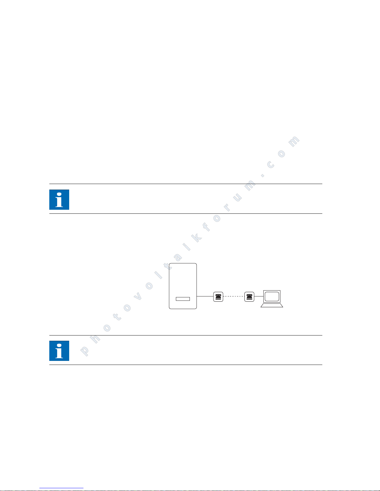
Operation
68 PT 30k to PT 33k
Procedure:
1. Connect your Solar Inverter with your DSL router. Use a CAT5 Ethernet cable
with 1:1 RJ45 sockets. The master is connected to the network as standard.
2. Register free of charge, e.g. at www.dyndns.org.
3. Create a so-called alias for the access to your solar inverter, for example PT
series.dyndns.org. You can access your Solar Inverter later via this address.
4. Configure your DSL router such that the IP address is regularly reported to
www.dyndns.org (follow the procedure described in the manual for your
DSL router for this purpose).
5. Configure your DSL router so that it accepts queries from the Internet (e.g.
via port 80) and forwards them internally to the Solar Inverter (port forwarding).
6. Also note that the port for access from the Internet set in your firewall must
be enabled.
NOTE
On the Internet you will find instructions for configuring frequently used DSL
routers.
Connection via the Sunways
modem
A modem connection can be used to bridge longer distances during system monitoring and configuration. The Sunways modem is connected to the Solar Inverter for this purpose. The Sunways modem is available as an analog, ISDN and
GSM type.
1. Connect your Solar Inverter and the remote modem with a 1:1 Ethernet connection cable, type CAT5 with RJ45 sockets.
NOTE
In a networked system, only the main unit should be connected to the remote
modem as standard.
2. Connect an external modem to your PC or use the internal modem of the
PC if available. For commissioning, please refer to the Sunways modem user
manual.
PC
INVERTER
Modem Modem
max. 100 m
photovoltaikforum.com
Page 71
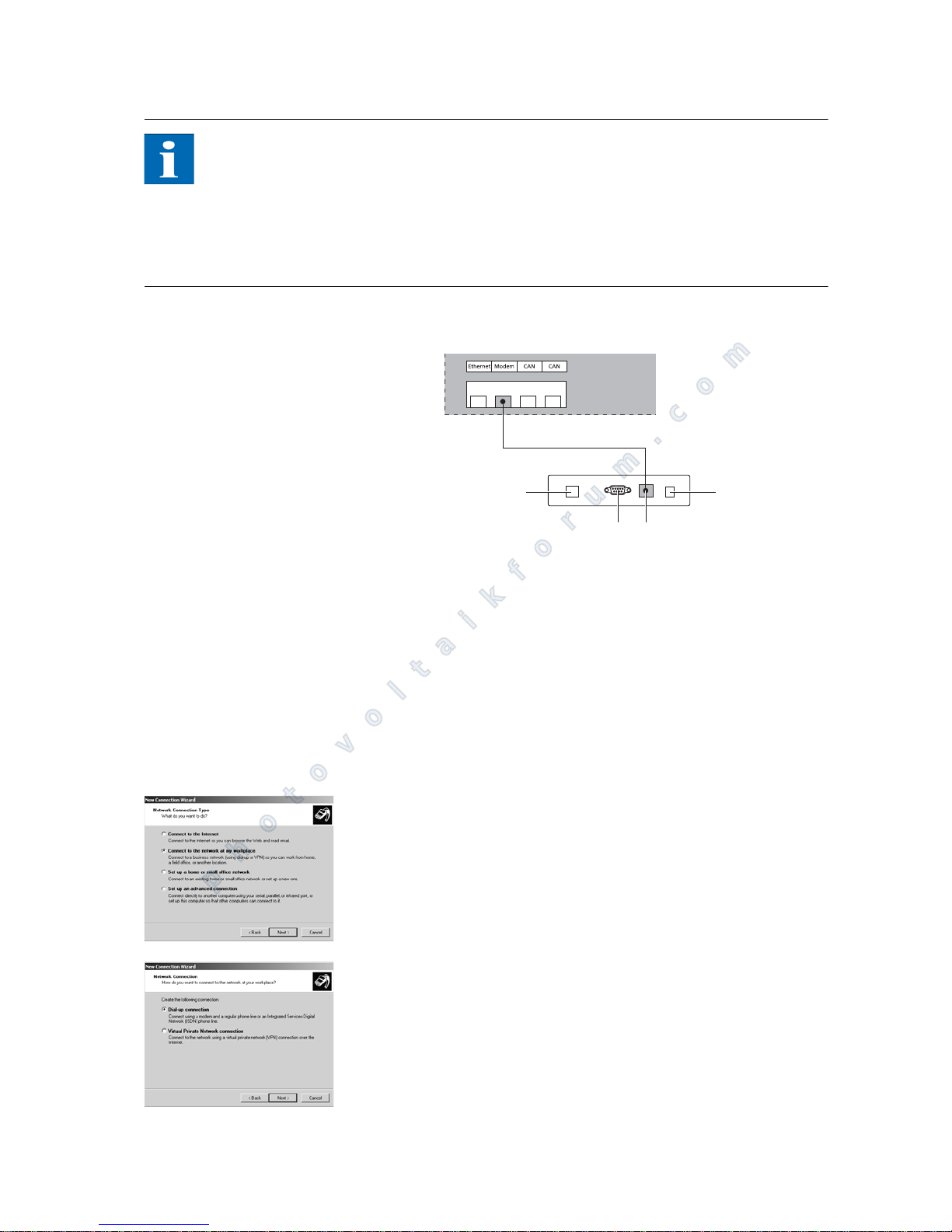
Operation
PT 30k to PT 33k 69
NOTE
The following modem combinations are permitted:
ISDN – ISDN
analog – analog
analog – GSM
GSM – analog
GSM – GSM
Connecting the Sunways modem
1 Telephone connection
2 RS232 interface
3 LVDS for NT, AT and PT Solar Inver-
ter
4 Power supply unit
Dialling in from a PC to the Solar Inverter
To establish a connection to your Solar Inverter with a PC via the modem, you
must establish a dial-up connection in Windows. The procedure under
Windows
®
XP is shown below.
1. Run the wizard for a new connection via "Start – Settings – Network Connections".
The first selection screen is opened with "Continue".
2. Select "Connection to the network on My Computer" and confirm your
choice with "Continue".
3. Select "Dial-up connection" on the next screen and click "Continue".
41
2 3
INVERTER
MODEM
photovoltaikforum.com
Page 72
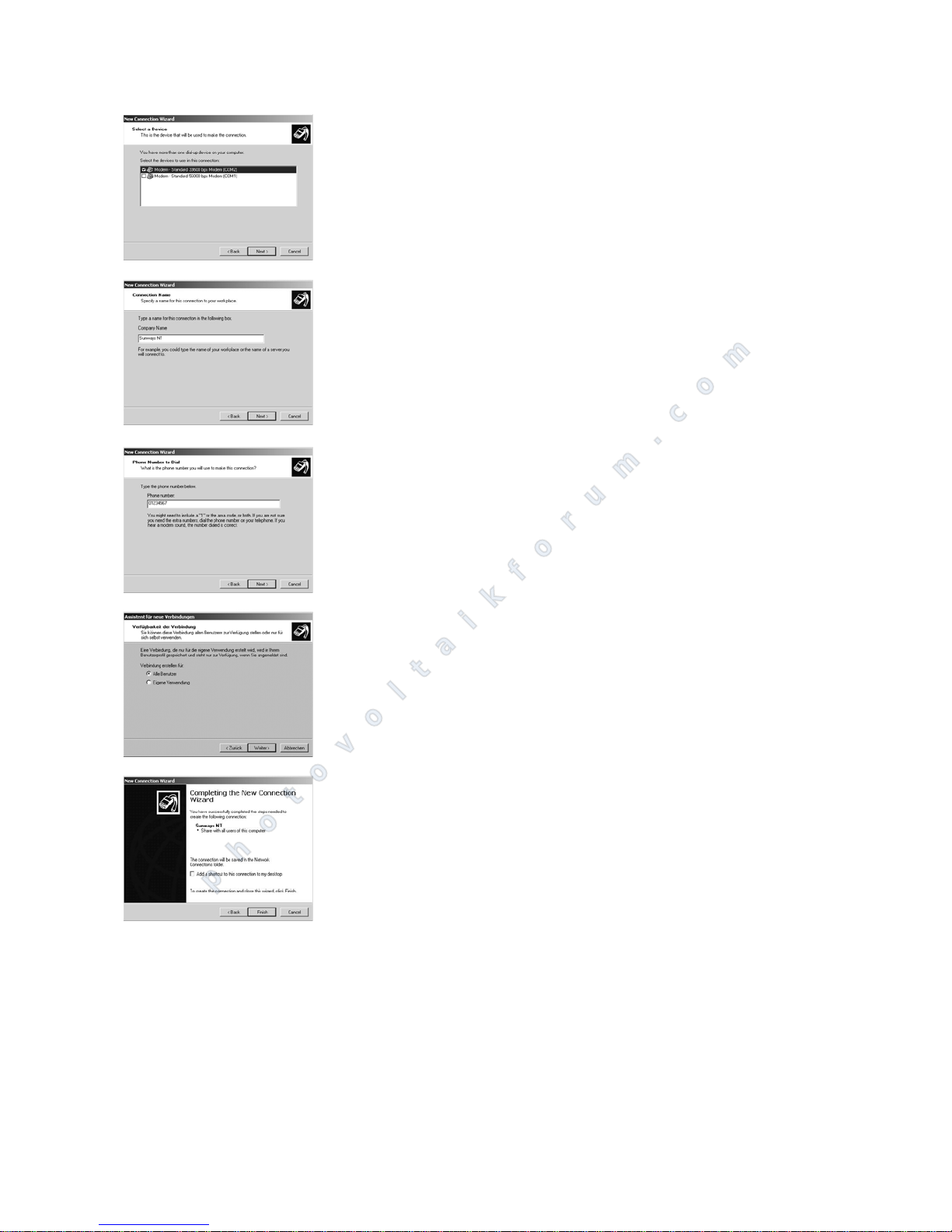
Operation
70 PT 30k to PT 33k
4. A list of the installed modems appears. Select the required modem and click
"Continue".
5. Enter a connection name and confirm your entry with "Continue".
6. Specify the phone number of your Sunways unit.
When entering the telephone number, you may need to include one or
more digits to connect to an outside line. (An outside line is usually obtained by placing a "0" before the actual telephone number.)
Confirm your entry with "Continue".
7. In this screen you can specify whether or not this connection is to be available to all users of this PC. If in doubt specify "All users" and click "Continue".
8. Click the checkbox to place a shortcut on your desktop and click "Finish".
photovoltaikforum.com
Page 73
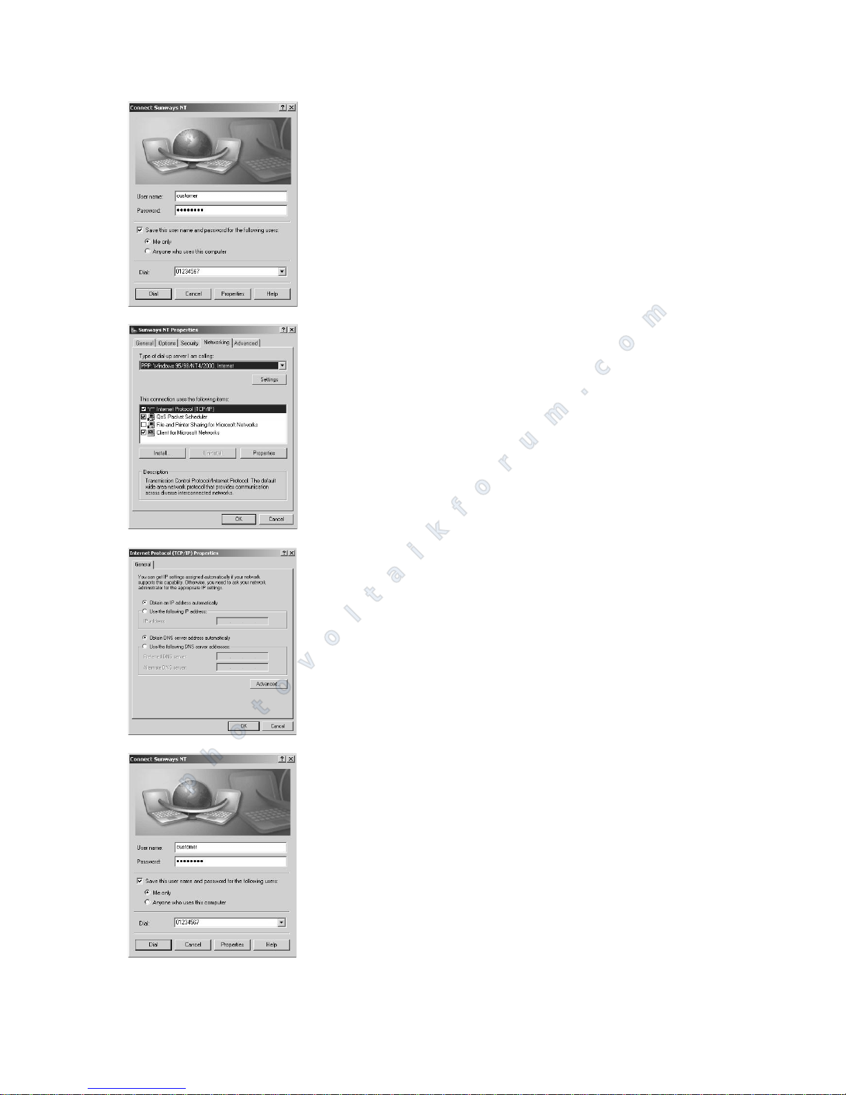
Operation
PT 30k to PT 33k 71
9. The connection window appears automatically after finishing the connection. (Alternatively via the icon on your desktop or via "Start – Settings –
Network Connections".)
Further settings are required in the "Properties" section.
10. First select the "Network" tab and mark the entry "Internet Protocol" (TCP/
IP) there.
Select "Properties".
11. Enter the following data:
Obtain an IP address automatically
Obtain DNS server address automatically
12. Enter "customer" as the user name and the standard password (********,
i.e. 8 asterisks) or the password you entered previously.
photovoltaikforum.com
Page 74
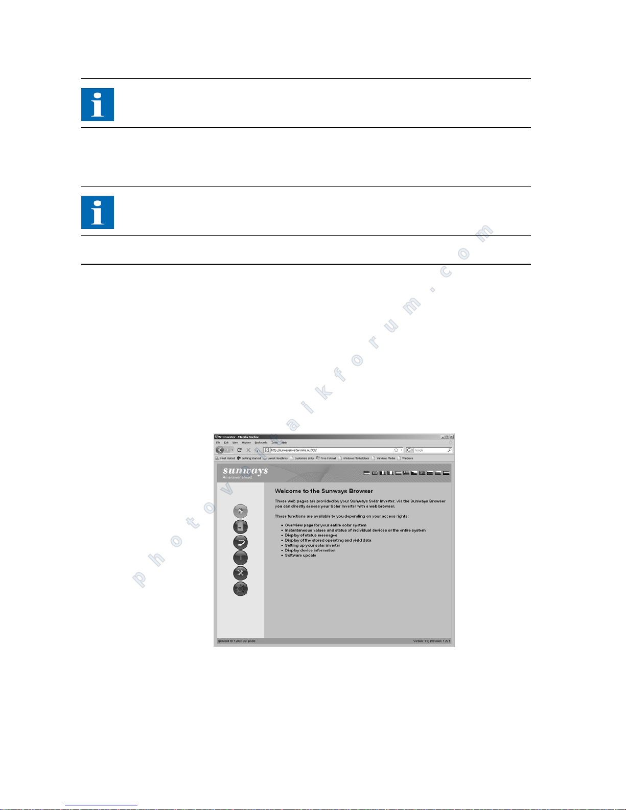
Operation
72 PT 30k to PT 33k
NOTE
The password matches the customer password on the unit.
13. The connection is established with "Dial". After the connection is established, you can start the Sunways browser by entering the IP address of the
Solar Inverter in the address line of your web browser.
NOTE
In contrast to the normal IP address for a modem connection, the IP address of
the Solar Inverter is set to 192.168.20.50 by default.
6.3 Sunways Browser
General information The Sunways browser can be run via a standard Internet browser, e.g. Mozilla
Firefox. One of the three possible connections between a PC and the Solar Inverter is required for this purpose (see section System monitoring):
Direct connection via an Ethernet cable or internal network
Connection via the Internet, e.g. connection of the unit to a DSL connection
Connection via a Sunways modem
The start screen opens once the IP address of the Solar Inverter has been entered
in the address line of the browser:
Here you can select from different languages.
The browser offers the following functions:
Display of the operating mode and instantaneous values for a single unit or
for a CAN-networked system
Display of energy yields as 5-minute, daily, monthly, annual and total values
photovoltaikforum.com
Page 75
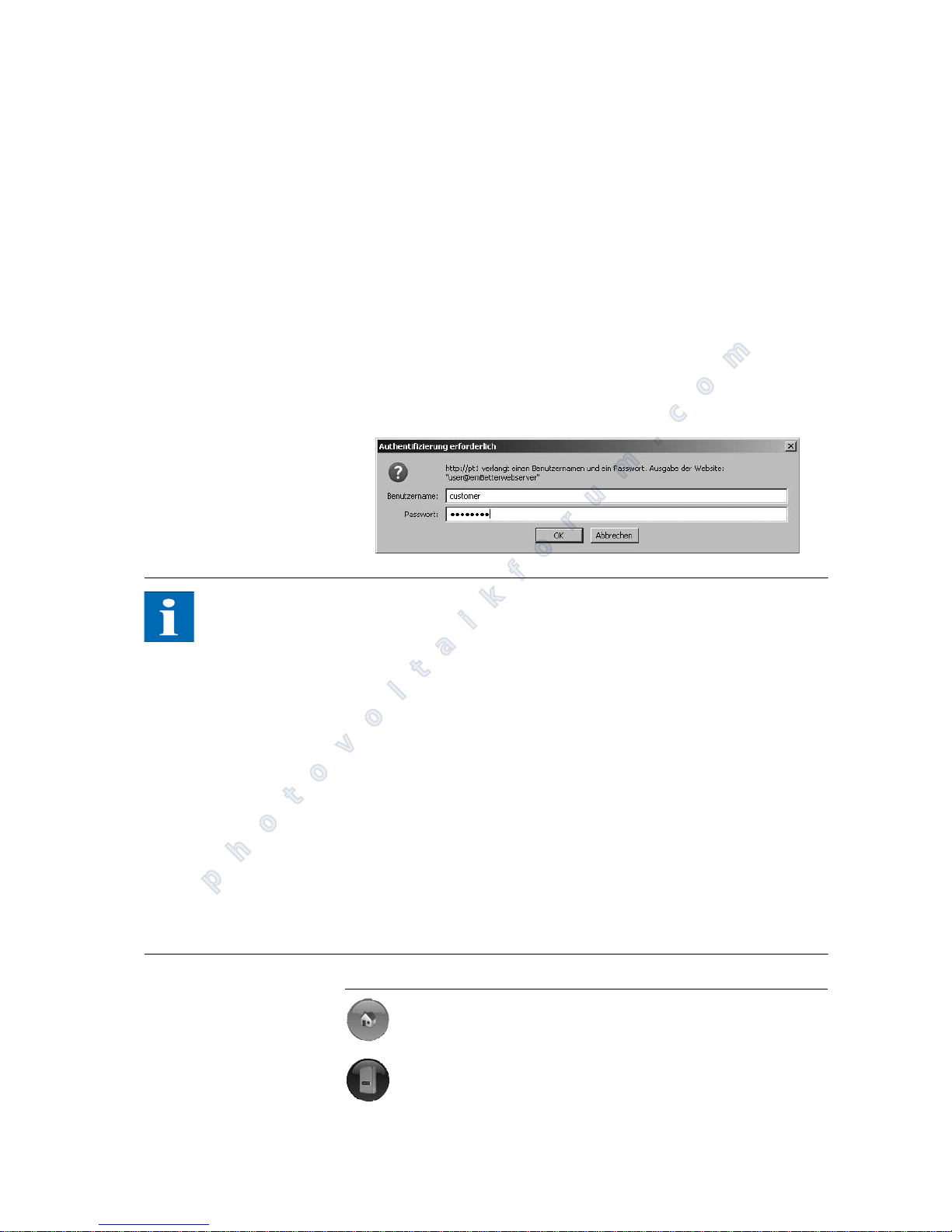
Operation
PT 30k to PT 33k 73
5-minute mean values of solar generator current and voltage, grid current
and voltage and feed-in power
Settings, e.g. of date/time, interface configuration, alerting options, commu-
nication parameters etc.
Communication software update (LCD display, interfaces, communication
and Sunways browser) and the control software (control and monitoring)
Access protection The Sunways browser is provided with password protection so that unautho-
rised persons cannot access your Solar Inverter.
The following user data are set in the delivered state:
User: customer
Password: ********
NOTE
It is recommended that you change this password to an 8-character/digit
password.
This password is identical to the password entered via the LCD display for set-
tings and commissioning.
Only digits between 0 – 9 and letters between a – z and A – Z are permitted.
The password always has 8 characters. If the password you entered has less
than 8 characters, the remaining characters are filled with *.
Example:
Your password is "Solar". This password has 5 characters. The system automatically appends three *, so that the password becomes "Solar***".
If you cannot remember the password, you can request a device-specific pass-
word from the Technical Hotline (Tel. 49 (0)7531 996 77-577) so that you can
access your Solar Inverter again. In this case, you need the serial number and
the MAC address which can be found on the type label.
Overview – Menu
Home – Display of start page
Solar Inverter – Displays instantaneous values, stored operating data, and the status of the unit
photovoltaikforum.com
Page 76
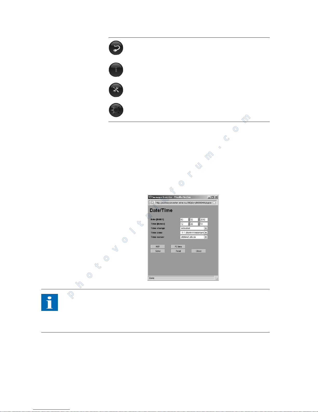
Operation
74 PT 30k to PT 33k
Language selection The web pages can be displayed in different languages. Click on the country
flags to switch to the respective language.
Setting date/time This function can be accessed via Settings – Date/Time. If you have selected the
correct time zone and an Internet connection is available, you can automatically
synchronise the time of the Solar Inverter with a time server with the NTP button.
As an alternative you can also transmit the PC time to the Solar Inverter.
NOTE
Please note that time settings should only be made with caution, as they directly
affect data logging. For example, if you set the time back by 1 hour, then the
existing data will be overwritten. Check the time regularly during the maintenance intervals for correct functioning and adjust the time at least 1x year if necessary.
Software update The software update is used to expand functions on your Solar Inverter. The
communication software (for LCD display, interfaces, communication and Sunways browser), the control software or the monitoring software can be updated.
Solar System – Displays a system overview with status, total output,
yields and access to slaves (only available if the unit is connected
with the master)
Information – Unit information, e.g. serial number
Settings and software update for the unit or the networked system
System information for your solar system such as name, capacity,
geographical location, a photograph and details of the components.
photovoltaikforum.com
Page 77
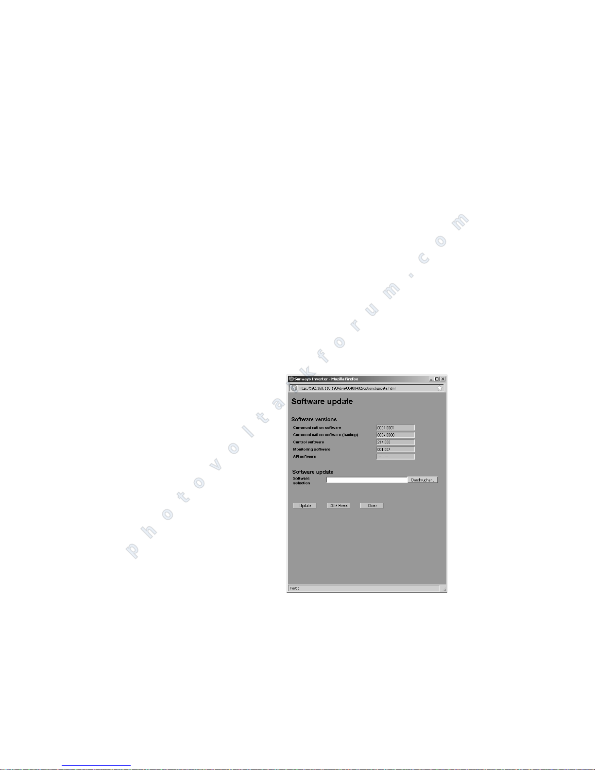
Operation
PT 30k to PT 33k 75
1. Call up the function "Settings – Software Update" for this purpose. This
function requires entry of a password (default: ******** = 8 asterisks or the
your own customer password).
2. The upper screen section shows the current software versions. If a new version is made available on our website (www.sunways.de), then you can
download this file and load it via the Sunways browser. Select the file on
your hard disk in the "File" field with the "Browse…" button and confirm
the file dialogue with "OK".
3. The current software is copied to the Solar Inverter with the "Update" button.
4. If necessary, for older units, select between: communication software and
control software.
For details, please refer to the detailed manual for software updates.
WARNING NOTICE: During a software update, the stored data of the minute values are deleted!
5. If a prompt appears to restart, please confirm with OK so that the installed
software is put into operation.
6. If "Critical Error" appears, the update for the web interface must also be installed.
7. The communications unit is restarted and the new software is loaded with
the "Restart" button.
Devices networked via CAN can be updated via the network. In this case the
software is distributed to the slaves via the master. Further details on the update manual can be found under: www.sunways.de
Internet dial-in via modem
Modem settings If you use a modem for the Internet connection, the modem must be set up ac-
cordingly via the Sunways browser. Therefore, first establish a connection between your PC and the Solar Inverter (see section Direct Ethernet connection).
photovoltaikforum.com
Page 78
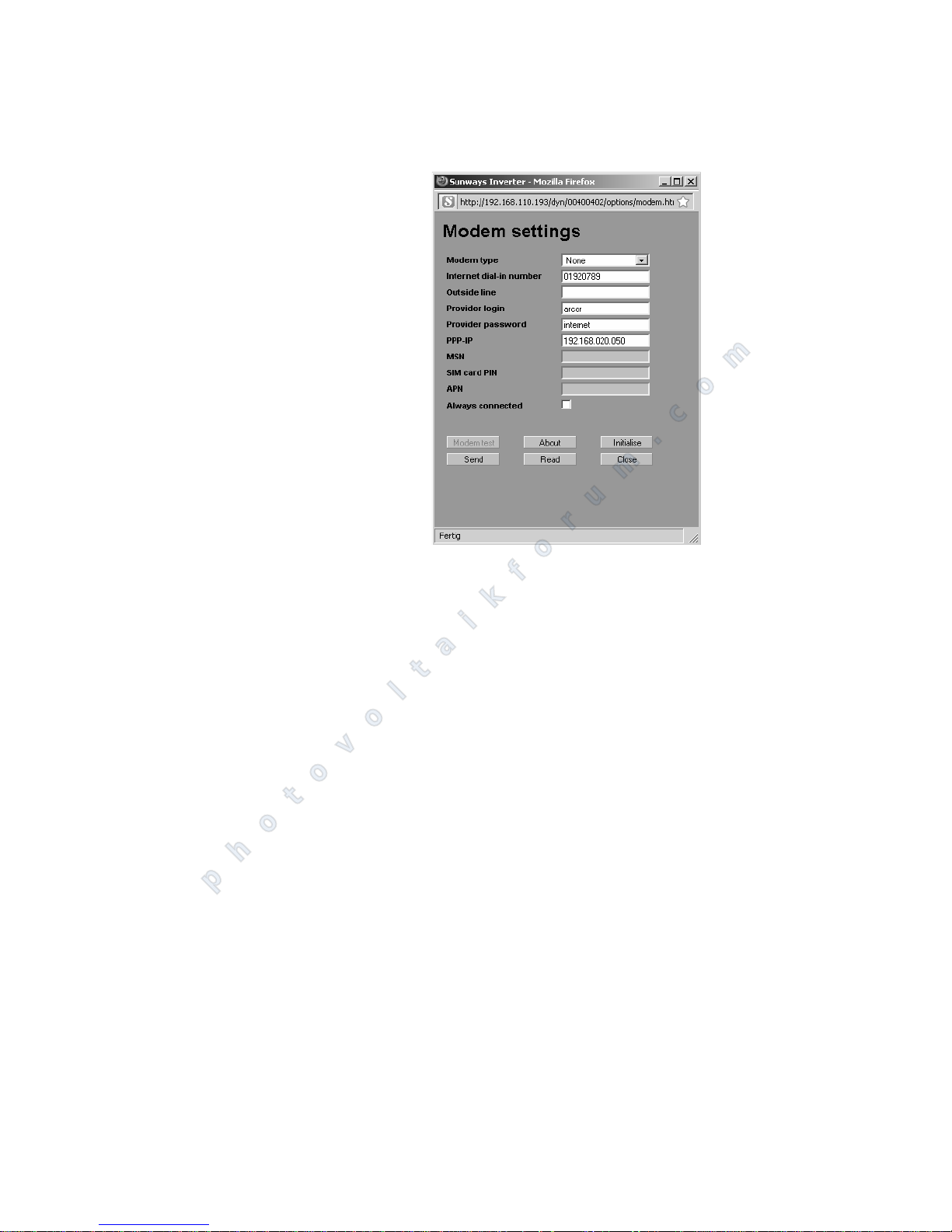
Operation
76 PT 30k to PT 33k
With the web browser, you can then make the following settings in the menu
"Settings – Modem":
Modem type Selection for the modem type: Analogue, ISDN or GSM modem
Internet dial-in number Dial-in number of your Internet provider (ISP)
Outside line If you have a telephone system, you can, for example, enter a 0 here. A comma
results in a dialling pause of 1 second.
Provider Login user name defined by your Internet provider
Provider password password defined by your Internet provider
PPP-IP you can reach the Solar Inverter by entering this IP address in your web browser.
The default address is 192.168.20.50.
MSN with an ISDN modem, you store the MSN of the extension to which the modem
is connected here. This is usually the telephone number of the extension without the area code.
SIM card PIN for a GSM modem, you enter the PIN of the SIM card here.
APN Access point number. You can obtain the APN from your mobile communica-
tions provider.
Always connected Select this option if you have a GPRS mobile tariff in order to ensure that the
device is always online.
photovoltaikforum.com
Page 79
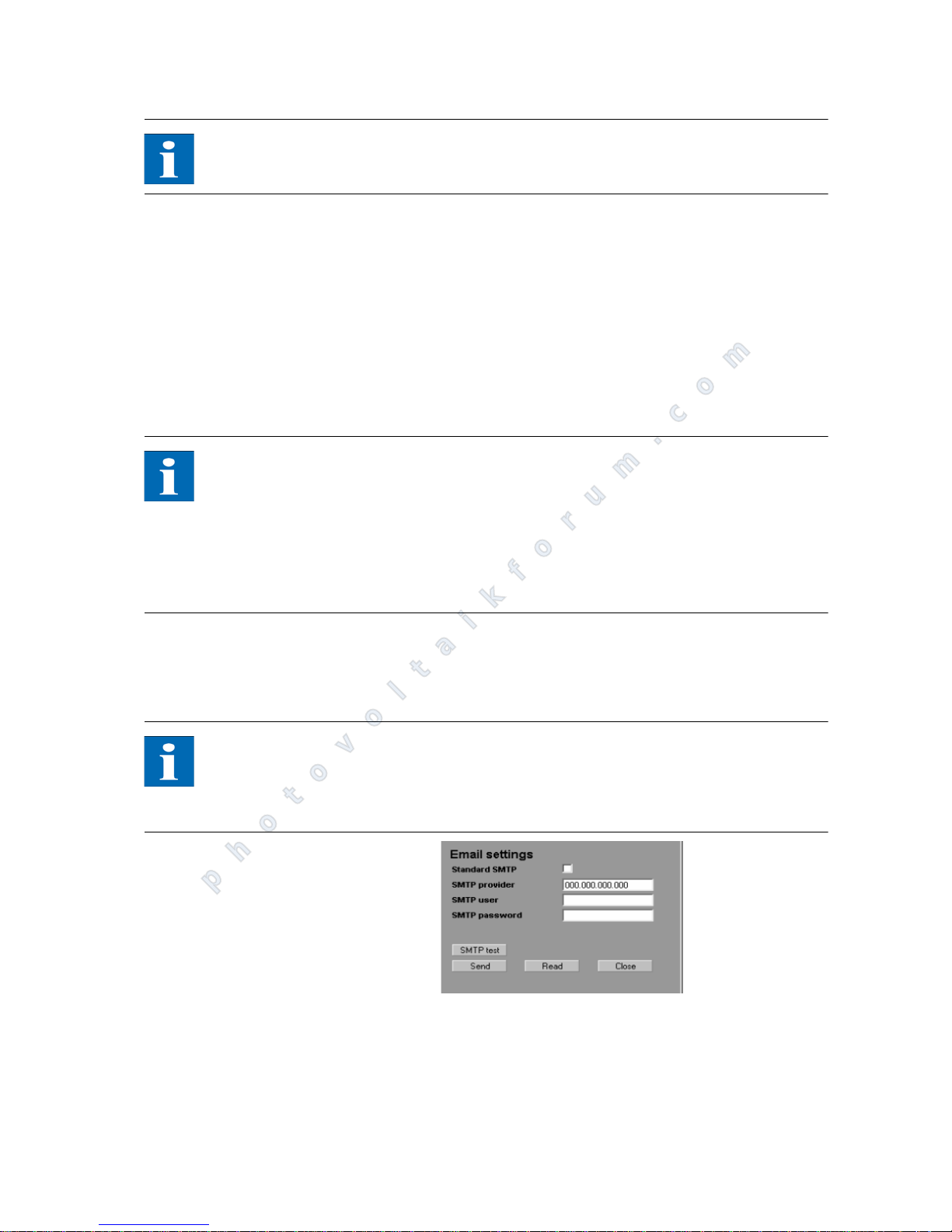
Operation
PT 30k to PT 33k 77
NOTE
Please note!!! With time-based tariffs (e.g. modem connection with GSM or
analog), this function can result in very high phone charges!
Function buttons Use the "Send" option to save the settings in the Solar Inverter.
Use "Read" to display the settings currently stored in the Solar Inverter.
With "Modem Test", you can test the modem connection to the set Internet
provider. You will receive feedback as to whether dialling in was successful.
Click "About" to obtain additional information about the modem.
Click "Initialise" to re-initialise the modem.
NOTE
Before conducting the modem test, the settings must be stored in the Solar
Inverter with "Send".
For example, you can select inexpensive dial-in numbers for Internet provi-
ders at www.teltarif.de/internet or www.billiger-surfen.de. Here you will
find not only tariff information, but also the access data (phone number,
user name, password).
E-mail settings In order for the Solar Inverter to be able to send e-mails, the e-mail settings
must be stored via the Sunways browser. The settings can be accessed via "Settings – Network" in the section "E-mail settings".
NOTE
Requirements:
When dialling in via modem, the correct dial-up settings must be stored (see
Internet dial-up via modem).
Standard SMTP If the standard SMTP server is activated, the e-mails are sent via a preconfigured
mail server.
SMTP provider SMTP server for sending e-mails, e.g. mail.gmx.net (max. 30 characters). Alter-
natively an IP address can be entered.
photovoltaikforum.com
Page 80
Operation
78 PT 30k to PT 33k
SMTP user User name for your e-mail provider (generally your e-mail address), e.g. Sun-
[email protected] (max. 50 characters)
SMTP password Password for your e-mail provider (max. 20 characters)
Function buttons Via "SMTP Test", you can send a test message to the e-mail address stored for
active alerting.
NOTE
Before conducting the SMTP test, the settings must be stored in the Solar In-
verter with Send.
During the SMTP tests an e-mail is sent to the e-mail address stored in the sys-
tem monitoring unit (active alerting). Before starting the test, check whether
a valid e-mail address is stored under active alerting.
If no login is set up on the configured SMTP server, the password field must
be left empty. The login field is entered as the sender address for the e-mail.
If no login is specified, the Solar Inverter sends the e-mail with a standard
sender address.
Use the "Send" option to save the settings in the Solar Inverter.
Use "Read" to display the settings currently stored in the Solar Inverter.
Active alerting
General information With active alerting, you can receive status messages (errors and warnings) for
your solar system by e-mail. If a status message was active for longer than 15 minutes or occurred 5 times in one day, you will receive an e-mail at the next full
hour, which is sent to the e-mail address stored in the Solar Inverter.
NOTE
The master sends the status messages of all units if they are CAN-networked.
Requirements:
The master must be connected to the Internet via a network or modem.
When dialling in via modem, the correct dial-up settings must be stored (see
Internet dial-up via modem).
Correct e-mail settings must be stored in the Sunways browser (see "E-mail
settings").
Alerting settings The alerting settings can be accessed with the "Settings – System Monitoring"
button in the "Active Alerting" section.
photovoltaikforum.com
Page 81
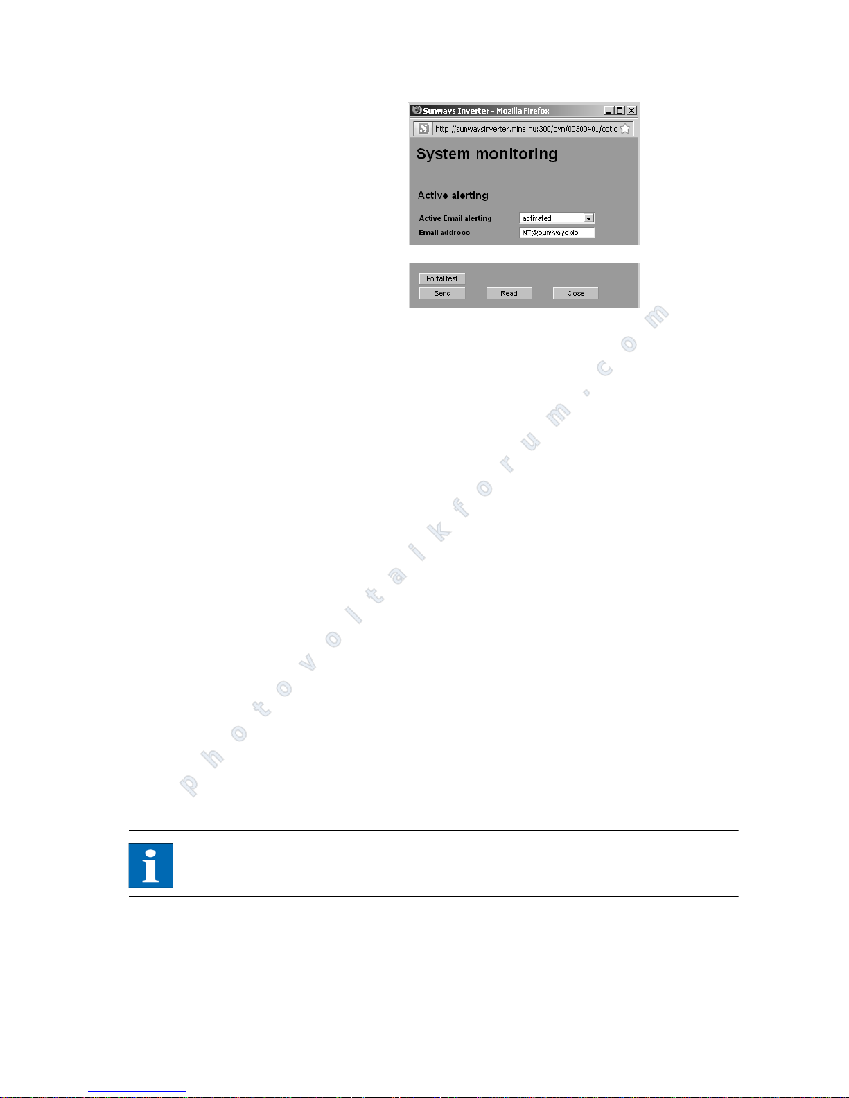
Operation
PT 30k to PT 33k 79
Active e-mail alerting Activation or deactivation of the active alerting function.
E-mail address In the email address field, enter the email address to which the messages are to
be sent.
Function buttons Use the "Send" option to save the settings in the Solar Inverter.
Use "Read" to display the settings currently stored in the Solar Inverter.
Sunways Portal connection
General information You can have the operating data of your solar system automatically sent to the
Sunways portal to monitor your system via the Internet. This is possible without
using a Sunways communicator.
The portal connection is configured via the Sunways browser. Following activation, the main unit automatically sends a registration e-mail containing the system data (e.g. number of units, serial number, etc.) to the Sunways portal.
After activation, the operating data for each day are sent to the Sunways portal
by e-mail on a daily basis before the main unit is switched off for the night. The
interval can also be set shorter as an alternative. If a change is made to your solar system (e.g. additional unit), then the change is automatically reported to
the Sunways portal.
A basis access for the Sunways portal for displaying the yield data is available to
every Sunways customer free of charge. Expanded functions, e.g. the setpoint-actual comparison in the Sunways portal, can also be purchased for a fee.
NOTE
The main unit sends the status messages of all units if they are CAN-networked.
Requirements:
The main unit must be connected to the Internet via a network or modem.
Correct e-mail settings must be stored in the Sunways browser (see "E-mail
settings")
photovoltaikforum.com
Page 82
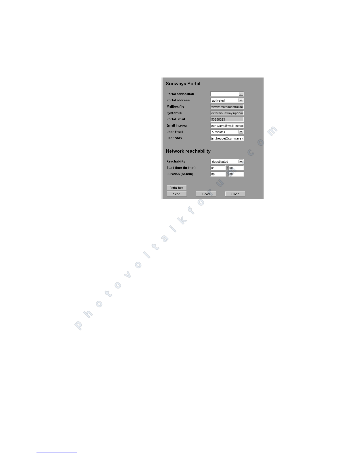
Operation
80 PT 30k to PT 33k
Correct portal settings must be stored in the Sunways browser.
Setup Check whether you meet all requirements. Configure the specified settings if
necessary via the Sunways browser according to the following procedure.
1. In the Sunways browser, call up the "Settings - System Monitoring" page
2. Tick the "Portal connection" checkbox to activate.
3. Select the send interval in the "Email interval" field. Be aware that these settings influence telephone costs depending on the type of connection.
4. In the "User e-mail" field, store the e-mail address to which the login confirmation of the Sunways portal should be sent.
5. Optionally, you can store your mobile phone number in the "User SMS" field.
6. The settings you selected are accepted by pressing the "Send" key.
7. You will immediately receive an e-mail with an activation link for the Sunways portal.
8. In the meantime, carry out a connection test to the portal by pressing the
"Portal Test" button. If successful, the system ID of the Sunways portal is automatically entered in the corresponding field. You will also receive notification on the stored mobile phone number.
9. Follow the activation link in the e-mail and log on in the Sunways portal with
the user name and password from your e-mail.
10. Logging on the solar system: Choose between: New login for a new installation or replacement of the unit (if the main unit has been replaced).
11.In the Sunways portal, change your login data (user name and password) in
the "Administration" menu under "Password".
12. Now select the "Administration - System Data" menu. Please insert the rated
power of the generator field via the "Subsystem" function.
13.If required, you can purchase the professional access to the Sunways portal
via the "Administration - Contract status" menu. Comprehensive monitoring
functions for your solar system are made available.
photovoltaikforum.com
Page 83
Maintenance
PT 30k to PT 33k 81
7 Maintenance
7.1 Servicing schedule
Regular maintenance is required in order to ensure sound operation of the Solar
Inverter. Maintenance is carried out in accordance with the commissioning and
maintenance reports of Sunways.
DANGER
Maintenance may only be carried out by qualified staff. Dangerous voltages!
Touching live parts can result in death.
All electrical work must be carried out by a qualified electrician while obser-
ving the VDE regulations, national and other regulations.
The checks must be carried out based on the recognised state of the art and
the regulations specified by employers' liability insurance associations.
The specified sequence of tasks and checks must be followed.
7.2 Maintenance interval
The PT series must be serviced once a year.
Initial service should be carried out no later than 12 months after commissioning.
The following maintenance tasks should be carried out once per calendar year.
The service must be carried out no later than 2 months after the month in which
the unit was commissioned. Air inlet grilles may need to be cleaned more frequently in installation locations with increased soiling.
NOTE
The service can be undertaken by Sunways or a service partner as part of a service agreement with Sunways.
7.3 Maintenance tasks
Wiring Visual inspection and measurement of all AC and DC cables between the modu-
le and the public grid of the energy supplier (terminals and transitions).
photovoltaikforum.com
Page 84
Maintenance
82 PT 30k to PT 33k
Solar generator connection
box
DANGER
Extreme danger from electric shock!
The main DC switch in the inverter must be in the "0" position.
Measurement configuration at the inverter output of the module connection
box, close the DC fuse holder for the string to be measured, record the result,
fold out the fuse holder and measure other strings in the same way if required.
1. Check the open circuit voltage for each string
2. Check the short circuit current for each string
3. Measure the DC voltage
4. Measure the mains voltage
5. Connection test
6. Check the MPP status
7. Check the MPP voltage
Inverter 1. Carry out filter cleaning (IP 42, IP 54 variants)
If the filters are too dirty, replace them.
In each case, two filter mats at the top (only for IP54 variant) and two filter
mats in the base of the unit should be replaced. To replace the filter mats in
the base, release the bolts at the side and fold the module downwards.
2. Clean the air inlet grilles (IP 5
5/Outdoor variant)
3. Check the connectors. Done and OK?
4. Connection bolts checked and OK?
5. Visual inspection of the interior for assessing the electrical components.
Particular attention must be paid here to potential damage caused by small
animals and insects, as it is possible for them to enter the housing through
cable glands which have not been closed properly or through open front or
back doors.
6. Check overvoltage protection.
7. Software updates if new software is available.
8. Grid connection: Visual inspection of the transformer housing and the electricity meter.
9. Manual current and voltage measurements with multimeter and current
probe for all strings. (Voltage-proof tool at least 1000 V DC)
10.Insulation measurements for the individual strings.
photovoltaikforum.com
Page 85
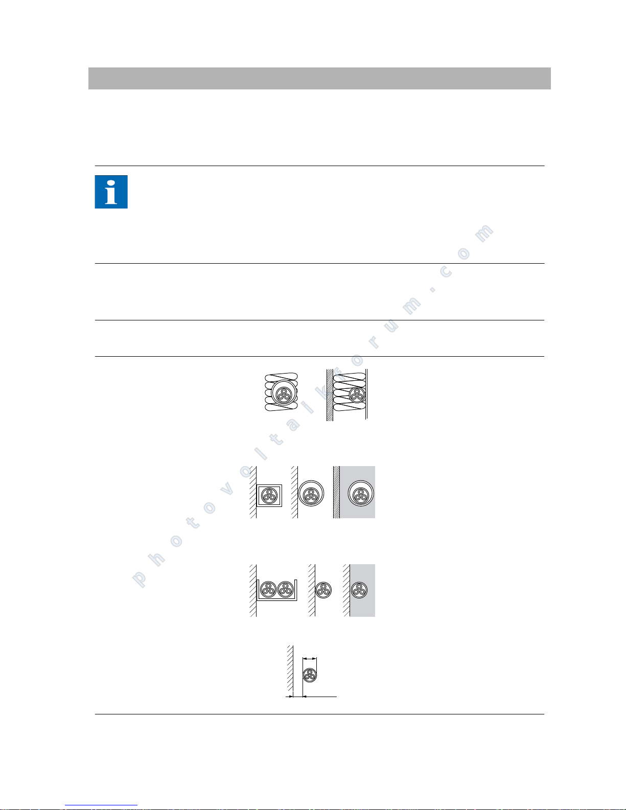
PT 30k to PT 33k 83
A Appendix
A.1 Installation methods and cable cross-sections
This is an overview of the contents of DIN 0294-8 / EN60204-1. The data in the
standard are relevant and must be used.
NOTE
The data is based on an ambient temperature of 30C according to test con-
ditions and a cable temperature of up to 70C.
Number of wires under load: 3
Line accumulation must be taken into account.
Reference installation methods A2, B2, C, E for fixed installation of cables and
lines in and on buildings according to DIN VDE 0298-4/2003:
*) not applicable for installation on wooden walls
Installation method Diagram Rated current for the LS switch
10 mm
2
Cu 16 mm2 Cu 25 mm2 Cu
Installation method A2
Installation in thermally insula-
ted walls
Multi-core or sheathed cables
Directly installed in electrical
conduits or ducts
--63A
Installation method B2
Installation in electrical condu-
its or enclosed electrical service
ducts on or in walls, or in ducts
for underfloor installation
Multi-core or sheathed cables
-63A80A
Installation method C
Direct installation on or in
walls/slabs or in cable troughs
Multi-core or sheathed cables
63 A* 80 A 100 A
Installation method E
Installation in air, on support
cables or on cable racks and
brackets
Multi-core or sheathed cables
63 A* 80 A 100 A
d
≥0,3d
photovoltaikforum.com
Page 86

84 PT 30k to PT 33k
A.2 General liability disclaimer
Although information contained in this manual has been checked with the greatest care for its accuracy and completeness, no liability whatsoever can be accepted for errors or omissions.
Sunways AG reserves the right to change the hardware and software fea-
tures described here at any time without prior notice.
This manual may not be reproduced, passed on, copied or translated into
other languages in whole or in part in any form or with any means without
prior written approval by Sunways AG.
Sunways AG shall assume no guarantee for damage caused by faulty or lost
data due to incorrect operation or the malfunction of the unit, the software,
additional devices or PCs.
All rights reserved. © Sunways The products named on cover page are protected by copyright and sold under
licence. No part of this document may be reproduced in any form without prior
written approval of Sunways.
Registered trademarks HERIC
®
is a registered trademark of Fraunhofer Gesellschaft, Munich.
photovoltaikforum.com
Page 87

photovoltaikforum.com
Page 88

Sunways AG
Photovoltaic Technology
Macairestraße 3 - 5
D - 78467 Konstanz
Telefon +49 (0)7531 996 77-0
Fax +49 (0)7531 996 77-444
E-Mail [email protected]
www.sunways.de
Technical Hotline +49 (0) 7531 996 77-577
SD130612A 05/12 EN
photovoltaikforum.com
 Loading...