

Page 1
User Manual
Sunways Solar Inverter
NTX 3000/4000/5000/6000
english
EN
Page 2

Copyright Declaration
Copyright @ 2011 SUNWAYS AG. All rights reserved.
No part of this document may be reproduced, stored in a retrieval system, or transmitted, in any form or by
any means, electronic, mechanical, photographic, magnetic or otherwise, without the prior written permission of SUNWAYS AG.
SUNWAYS AG makes no representation, express or implied, with respect to this documentation or any of the
equipment and/or software it may describe, including(with no limitation) any implied warranties of utility,
merchantability, or fitness for any particular purpose. All such warranties are expressly disclaimed. Neither
SUNWAYS AG nor its distributors or dealers shall be liable for any indirect, incidental, or consequential damages under any circumstances. (The exclusion of implied warranties may not apply in all cases under some
statutes, and thus the above exclusion may not apply.)
Specifications are subject to change without notice. Every attempt has been made to make this document
complete, accurate and up-to-date. Readers are cautioned, however, that SUNWAYS AG reserves the right to
make changes without notice and shall not be responsible for any damages, including indirect, incidental or
consequential damages, caused by reliance on the material presented, including, but not limited to, omissions, typographical errors, arithmetical errors or listing errors in the content material.
All trademarks are recognized even if these are not marked separately. Missing designations do not mean
that a product or brand is not a registered trademark.
SUNWAYS AG
Max-Stromeyer-Strasse 160,
D-78467 Konstanz, Germany
E-mail: [email protected]
www.sunways.de.
Page 3
Important Safety Instructions
3
IMPORTANT SAFETY INSTRUCTIONS
Save these instructions
This manual contains important instructions for NTX
inverter, that must be followed during installation
and maintenance of the inverter.
The NTX is designed and tested according to international safety requirements, but as with all electrical and electronic equipment, certain precautions
must be observed when installing and/or operating
the NTX. To reduce the risk of personal injury and
to ensure the safe installation and operation of the
NTX. You must carefully read and follow all instrucions, cautions and warning in this user manual.
Warning in this document
This manual provides safety operation information
and uses the symbol in order to ensure personal and
property security and use the inverter efficiently
when operating the inverter. You must understand
and absolute these emphasize information to avoid
the personal injury and property loss. Please read
the following symbols which used in this manual
carefully.
DANGER
DANGER indicates a hazardous situation which, if
not avoided, will result in death or serious injury.
WARNING
WARNING indicates a hazardous situation which, if
not avoided, could result in death or serious injury.
CAUTION
CAUTION indicates a hazardous situation which,
if not avoided, could result in minor or moderate
injury.
NOTICE
NOTICE is used to address practices not related to
personal injury.
Other symbols in this document
In addition to the safety and hazard symbols
described in the previous pages, the following symbols are also used in this user manual:
Remark:
These symbols note that call attention to supplementary information that you must know and use to
ensure optional operation of the system.
Marking on this product
The following symbols are used as product marking
with the following means.
Warning regarding dangerous voltage
The product works with high voltages. All work on
the product must only be performed as described in
its documentation.
Electric arc hazards
The product has large electrical potential differences between its conductors. Arc flashes can occur
through air when high-voltage current flows. Do
not work on the product during operation.
Beware of hot surface
The product can become hot during operation. Do
not touch the product during operation.
Page 4
Important Safety Instructions
4
General Warnings
GENERAL WARNINGS
All electrical installations must be done in accordance with local and National Electrical Code® ANSI/
NFPA 70. For installation in Canada the installations
must be done in accordance with applicable Canadian standards.
The NTX contains no user-serviceable parts except
for the fans on the buttom of the enclose and the
filters behind the fans. For all repair and maintenance, always return the unit to an authorized
Sunways Service Center.
Before installing or using the NTX, read all of the
instructions, cautions and warnings in the user
manual.
Before connecting the NTX to the electrical utility
grid, contact the local utility company. This connection must be made only by qualified personnel.
Warning of the NTX must be made by qualified
personnel only.
WARNING
Risk of electric shock and fire. Use only with PV
modules with a maximum system voltage of rating
of 550 V or lower.
Observe the operating instructions
Read the product’s documentation before working
on it. Follow all safety precautions and instructions
as described in the documentation.
AC current
DC current
Earth Ground
UL 1714 is the standard applied by Canadian Standards Association to the NTX to certify that it meets
the requirements of National Electrical Code
®
and
functionality necessary to ensure compatible operation when power generation is connected to the
utility grid.
Page 5

Contents
5
Contents
1 Notes on this manual 8
1.1 Validity 8
1.2 Target group 8
1.3 Storage of the documentation 8
1.4 Additional information 8
1.5 Nomenclature 8
2 Safety 9
2.1 Appropriate usage 9
Anti-Islanding protection 10
PV series fusing 10
Operating temperature 10
Interconnection code compliance 10
FCC compliance 10
2.2 Safety instructions 11
2.3 Installation overview 11
3 Unpacking and inspection 12
3.1 Scope of delivery 12
3.2 Product label 13
4 Mounting 14
4.1 Safety 14
4.2 Package inspection 14
4.3 Installation precaution 15
4.4 Preparation 16
4.5 Installation steps 16
5 Electrical connection 19
5.1 General electrical connection procedure
of NTX inverter 20
Pin Definition 21
Wiring procedure of NTX inverter 23
Page 6

Contents
6
5.2 Opening wiring cover of NTX inverter 23
5.3 AC wiring 23
AC voltage configuration 24
AC wiring procedure 25
5.4 DC wiring 26
Configuring the DC input channel 26
DC wiring procedure 27
Connection to a single PV array
(NTX 4000/5000/6000) 27
Parallel Connection to 2 PV arrays
(NTX 4000/5000/6000) 28
Two MPPTS connection to 2 PV arrays or
4 PV arrays (NTX 4000/5000/6000) 28
Connection to 1 PV array or 2 PV arrays
(NTX 3000) 28
5.5 Communication wiring 29
6 Commissioning 31
7 Display and messages 32
7.1 LED indicators 32
7.2 Available Data 33
Real-time operational data 33
Internally logged data 33
7.3 LCD display and operation 33
Display upon start-up 33
Default Menu 34
Main Menu 34
Running Menu 34
Setting Menu 35
Event 39
Service 39
8 Troubleshooting 40
8.1 General 40
8.2 Messages and Error Codes 41
9 Maintenance 44
9.1 Cleaning the fans 44
9.2 Checking the DC Disconnect 44
Page 7

Contents
7
10 Technical data 45
10.1 FCC compliance information 45
10.2 NTX wiring diagrams 46
NTX connections for 208 V and 240 V
AC grids 46
NTX connections for 277 V AC grids 46
10.3 Technical data 47
10.4 Trip limits/trip times 48
11 Contact 51
12 Notes 52
Page 8

1 Notes on this manual
8
1 Notes on this manual
1.1 Validity
This manual describes the assembly, installation,
commissioning and maintenance of the following
Sunways inverters:
NTX 3000
NTX 4000
NTX 5000
NTX 6000
This manual does not cover any details concerning
equipment connected to the NTX (e.g. PV modules).
Information concerning the connected equipment is
available from the manufacture of the equipment.
1.2 Target group
This manual is for qualified personnel. Qualified
personnel have received training and have demonstrated skills and knowledge in the construction
and operation of this device. Qualified personnel
are trained to deal with the dangers and hazards
involved in installing electric devices.
1.3 Storage of the documentation
Keep all NTX manuals in a convenient place for
future reference.
1.4 Additional information
You will find further information on special topics in
the download area at WWW.SUNWAYS.EU/EN.
1.5 Nomenclature
In this document SUNWAYS AG is referred to the following as Sunways.
Page 9
2 Safety
9
2 Safety
2.1 Appropriate usage
The NTX is a DC to AC grid-tied utility interactive
inverter for use with photovoltaic (PV). In general,
the NTX takes power from a DC source (PV modules)
and converts it to AC power for the utility grid. This
power is delivered first to local loads (household
appliance, lights, motor loads, etc.), with any excess
power fed to the utility. The power consumed by
the local loads reduces the power needed from the
utility. Excess power may actually spin the utility
meter backwards depending on the type of meter
in you system. This power may also be recorded as
power credits by the utility company depending on
the interconnection agreement. An example of basic
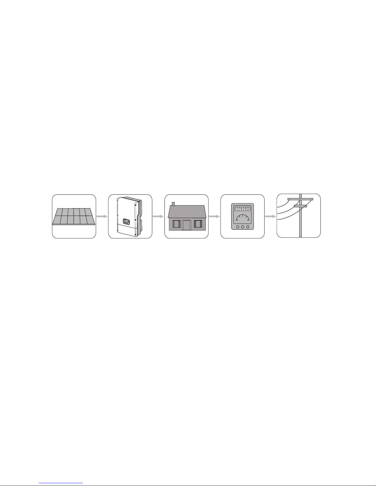
system components is shown in figure below.
Principle of a PV plant with a NTX:
1 2 3 4 5
1 PV array
2 NTX with DC Disconnect
3 Local loads
4 Energy meter
5 Utlity Grid
Remark:
Policies vary from one utility company to another.
Consult with a representative of the local utility company before designing and installing a PV
system.
Page 10
2 Safety
10
Anti-Islanding protection
Islanding is a condition that can occur if the utility
grid is disconnected while the NTX is operating and
the remaining load is resonant at 60 Hz and matches
the output of the NTX perfectly. This condition
is highly unlikely and had never been witnessed
outside of a controlled laboratory. Nevertheless,
the NTX incorporates an advanced active islanding
protection algorithm to ensure that the system will
not export power into a balanced 60 Hz resonant
load while the utility is disconnected. The NTX periodically injects both leading and lagging reactive
current into the utility grid. This method has been
proven by Canadian Standards Association to effectively destabilize and disconnect from a balanced
island condition.
The NTX is equipped with a ground isolation fault
detection device. If a ground isolation fault is
detected, the NTX will not run and display the fault
function on the user interface display. Once the
ground fault is located and corrected, the ground
fault error will need to be manually cleared and
the inverter will then resume normal operation
automatically.
PV series fusing
Series fusing may be required depending on the
type of PV module used in the system.
See NEC 690.9.
Remark:
For NTX 6000, the AC fuses are optional installed in
the unit. When not provided with the unit, it should
be provided at end installation.
Operating temperature
The NTX has been designed to maintain full
power output at ambient temperatures as high as
+113°F(+45°C). Fan cooling allows this level of output power to be achieved even in enclosed spaces.
The NTX will continue to operate well between
+113°F(+45°C) and +140°F(+60°C) and de-rates as
needed to maintain a safe internal component
temperature.
WARNING
Continuous storage time must be less than 3 months
below -13°F(-25°C).
Interconnection code compliance
The NTX has been tested and listed by Canadian
Standards Association to meet the requirements of
UL 1741 Static Inverters and Charge Controller for
use in Photovoltaic Power Systems and IEEE 1547
Standard for Interconnecting Distributed Resources
with Electric Power System. The NTX is also listed
under UL 1741 for Nationally Recognized Testing
Laboratory.
UL 1741 is the standard applied by Canadian Standards Association to the NTX to certify that it meets
the requirements of National Electrical Code
®
and
functionality necessary to ensure compatible operation when power generation is connected to the
utility grid.
Remark:
Contact the local utility and/or the authority having
jurisdiction prior to connecting the NTX to the utility
grid.
FCC compliance
The NTX has been tested and shown to confirm with
all FCC Part 15 B EMI/EMC emissions regulations.
Page 11
2 Safety
11
2.2 Safety instructions
DANGER
· High voltages are present in the NTX during
the operation. Death or seriously injury due to
electric shock.
· All work on the NTX must only be carried out by
qualified personnel.
WARNING
The NTX can become hot during operation.
Risk of burns: Do not touch enclosure during operation; Only touch panel during operation.
WARNING
When the NTX is running, connect it to the ground.
2.3 Installation overview
This section provides a brief overview of the installation process of NTX.
Section 3: Unpacking and inspection
This section provides instructions and information
for unpacking the NTX and inspecting it for shipping
damage.
Section 4: Mounting
This section includes guidelines to help you select
the best mounting location, suggestions to ensure
optimum performance, cautions and warnings that
you should follow to avoid injury and/or equipment
damage and step-by-step instructions for mounting
the NTX inverter.
Section 5: Electrical connection
This section includes configuration of AC voltage
and DC input channel, guidelines for selecting the
correct wire size, cautions and warnings that you
should follow to avoid injury and/or equipment
damage and step-by-step instructions for wiring the
NTX to a PV array, household electrical circuits and
the utility grid. Procedures are also included for connecting optional data-communication cables.
Section 6: Commissioning
Commissioning involves applying DC input power
to the NTX, observing the LED and LCD indicators
on the front cover, and resolving any problems that
occur.
Section 7: Displays and messages
This section provides messages for displays, settings
and faults during installation and operation.
Section 8: Troubleshooting
This section provides troubleshooting tips and
procedures for resolving problems that may occur
during installation and operation.
Section 9: Maintenance
This section includes maintenance and cleaning of
the NTX and cautions and warnings you should follow to avoid injury and/or equipment damage.
Section 10: Technical data
This section includes technical data for the NTX, connection diagrams and torque specifications for the
connection of cables and the screws of the NTX.
Page 12
3 Unpacking and inspection
All NTX inverters are thoroughly tested and
inspected before they are packed and shipped.
Although they are shipped in sturdy, recyclable
packaging, damage can still occur during shipping.
It is important to carefully inspect the shipping
container prior to beginning the installation. If any
external damage to the packaging makes you suspect the inverter itself could be damaged, or if you
find that the inverter is damaged after unpacking
it, report the damage immediately to your Sunways
dealer and to the shipping company that delivered
the NTX. If it becomes necessary to return the NTX,
use the original packaging in which it was delivered.
CAUTION
Failing of the NTX may cause injuries.
Crushing of body parts will result in injuries.
Take the weight of the NTX of 60.6 lbs. (27.5 kg)
into account when mounting.
If you need assistance with a damaged NTX, contact
your Sunways dealer or Sunways. Contact information is provided in section “11 Contact”, see page
51.
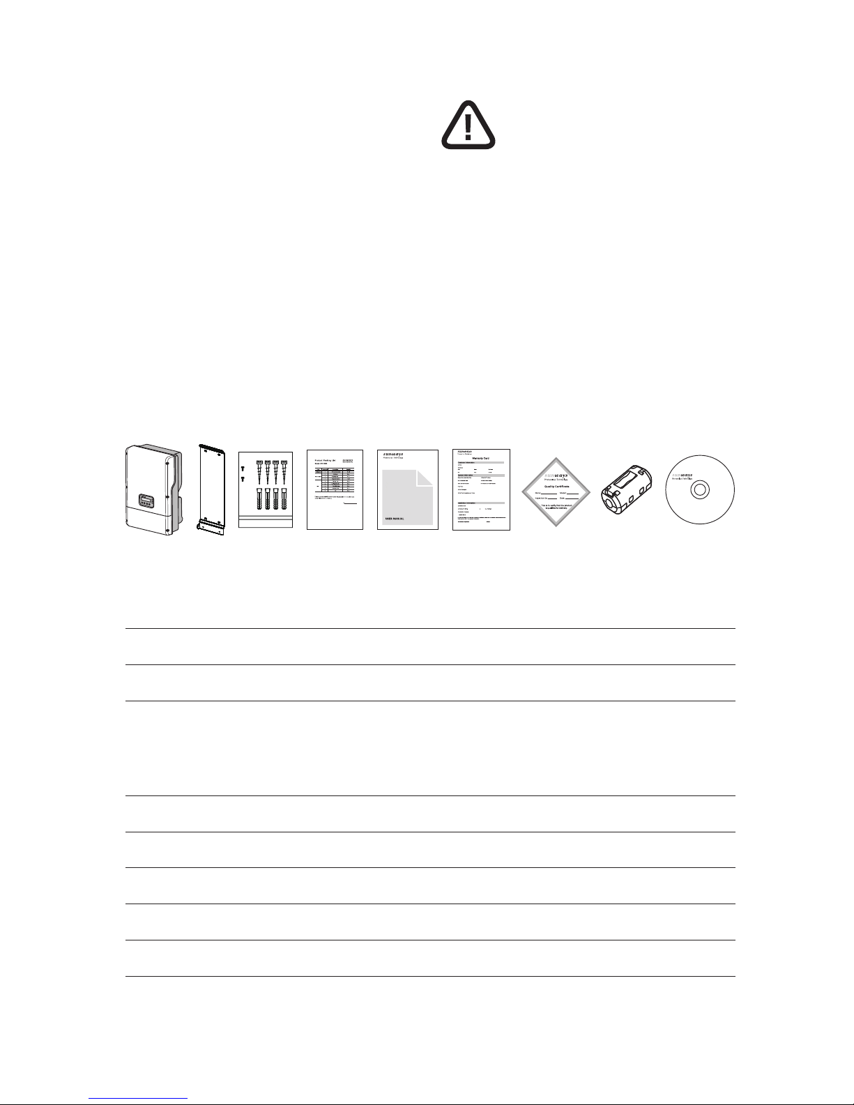
3.1 Scope of delivery
CD-ROM
Sunways Solar Inverter
NTX 3000
NTX 4000
NTX 5000
NTX 6000
Copyright
Sunways AG
Photovoltaik Technology
Max-Strohmeyer-Strasse 160
D-78467 Konstanz
Germany
SD101312A 12/12
Monitoring Software
Sunways NTX
EN
1 2 3 4 5 6 7 8 9
Position Number Description Remark
1 1 NTX series inverter –
2 1 Bracket –
3 1 Screw bag Screw bag containing:
Nr.4 M6x40 screws;
Nr.4 PEB8-38 wall plugs;
Nr.2 M6x10 screws.
4 1 Packing list –
5 1 Product manual –
6 1 Warranty card –
7 1 Quality certificate –
8 2 Magnetic buckle –
9 1 CD –
Page 13
3 Unpacking and inspection
13
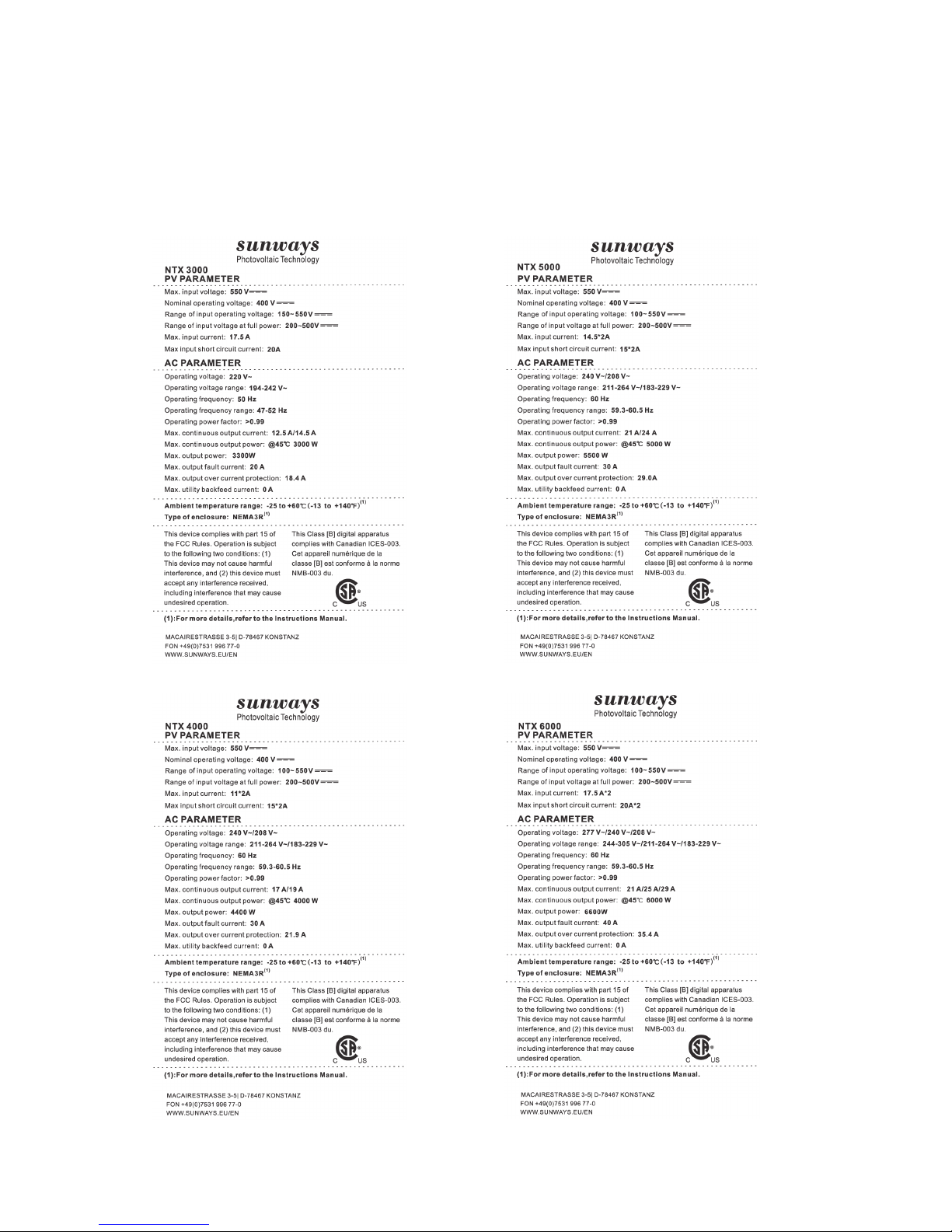
3.2 Product label
The product label provides basic information of the
inverter. Pay special attention to the type of inverter
and other specifications.
Page 14
4 Mounting
14
4 Mounting
4.1 Safety
WARNING
The electrical installation of the NTX inverter must
be performed in accordance with the electrical standards prescribed by the local regulations and by the
National Electric Code (ANSI/NFPA 70 standard).
WARNING
The connection of a NTX inverter to the electrical
distribution grid must be performed only receiving
authorization from the utility that operates the grid.
WARNING
Before installation and maintenance, AC and DC
side does not carry electricity. If DC side is just
disconnected, capacitance still contains electricity, so please wait for at least 5 minutes to ensure
the capacitors completely release the energy and
inverter is not electrified.
WARNING
Inverters must be installed by qualified person.
4.2 Package inspection
NOTE
The distributor delivered your NTX inverter to
the carrier safely packaged and in perfect condition. Upon acceptance of the package, the carrier
assumes responsibility for its safe delivery. In spite
of careful handing, transportation damage to the
package or its contents is always a possibility.
The customer is encouraged to perform the following checks:
· Inspect the shipping box for apparent damage,
such as holes, cracking, or any other sign of possible damage to its contents.
· Describe any damage or shortage on the receiving documents and have the carrier sign his/her
full name.
· Open the shipping box and inspect the contents
for internal damage. While unpacking, be careful
not to discard any equipment, parts or manuals.
If any damage is detected, call the delivering
carrier to determine the appropriate action. Save
all shipping material in the event that the carrier
sends an inspector to verify damage!
· If the inspection reveals damage to the inverter,
contact your supplier or authorized distributor.
They will determine if the equipment should
be returned for repair. They will also provide
instructions on how to get the equipment
repaired.
· It is the customer’s responsibility to file a claim
with the carrier. Failure to file a claim with the
carrier may void all warranty service rights for
any damage.
· Save the NTX series inverter’s original shipping
package in the event that you should ever need
to return the inverter for repair.
Page 15
4 Mounting
15
4.3 Installation precaution
Installation site should be selected based on the following considerations:
· The ambient temperature is in the range of
tolerable ambient temperature (-25°C to +60°C,
-13°F to +140°F);
· Lower than the altitude of about 2000m above
sea level;
· Unable to be damaged by sea water;
· Don’t be exposed to steam, vapor, or water;
· Far away from corrosive gas or liquid (for example, locations where chemicals are processed or
the location where feed lots of poultry).
· Far away from the television antenna or antenna
cable;
· Choose a location that allows unobstructed airflow around the inverter;
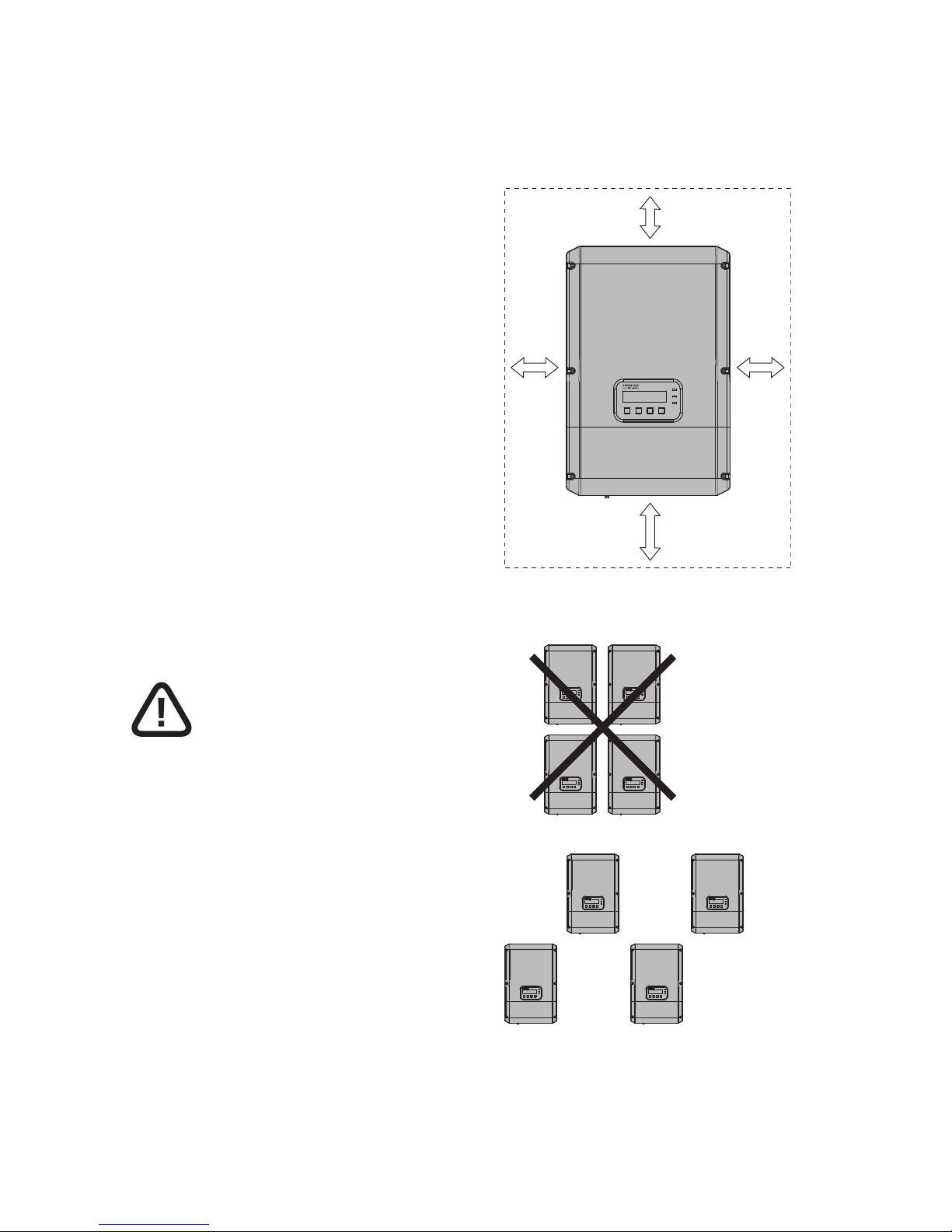
· Allow sufficient room around the inverter to
enable easy installation and removal from the
mounting surface.
WARNING
Not installing the inverter in the place mentioned
above may cause the malfunction of the system.
Sunways will not compensate the fault caused by
the above situation.
The following figures show the recommended
installation of the inverter:
Minimum clearance for NTX series inverter
300 mm 300 mm
200 mm
500 mm
Recommended arrangement
Page 16
4 Mounting
16
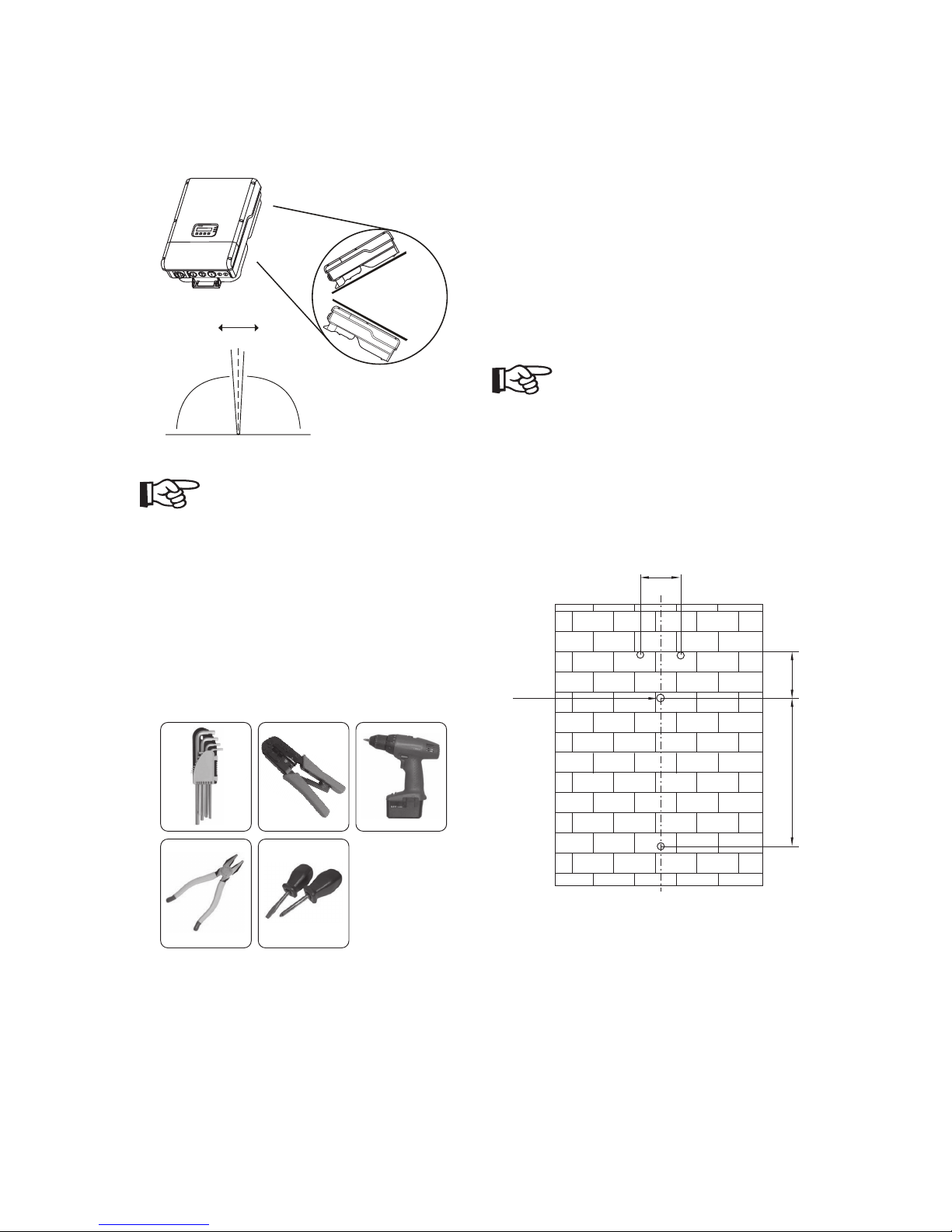
Recommended installation of NTX inverters
Tilted Mounting
Derating
NO Derating
Derating
Derating
-5° +5°
0°
NOTE
Vertical mounting is propositional. Tilted mounting
is permitted, but will reduce heat dissipation and
result in self-derating.
4.4 Preparation
Below tools are needed before installation:
Installation tools:
Crimping plier for binding post, crimping plier for
RJ45 and RJ11, screwdriver, allen wrench and Ø8
driller.
4.5 Installation steps
1. Drill holes in the concrete wall with Ø8 driller
according to the size of bracket. The size is
shown in following figure. Keep drilling vertical to the wall, and don’t shake when drilling
to avoid damage to the wall. The depth of the
holes should be about 45 mm and should be the
same. After removing the dust in the holes, measure the net depth of the holes. If the depth is
more than 50 mm or less than 40 mm, the expansion tubes wouldn’t be installed and tightened.
NOTE
When the wall is made of a different material (other
than concrete), the installation should be done
using adequate mounting material. Sunways recommends always using stainless steel screws.
The size of the holes
100
Ø8
375 110
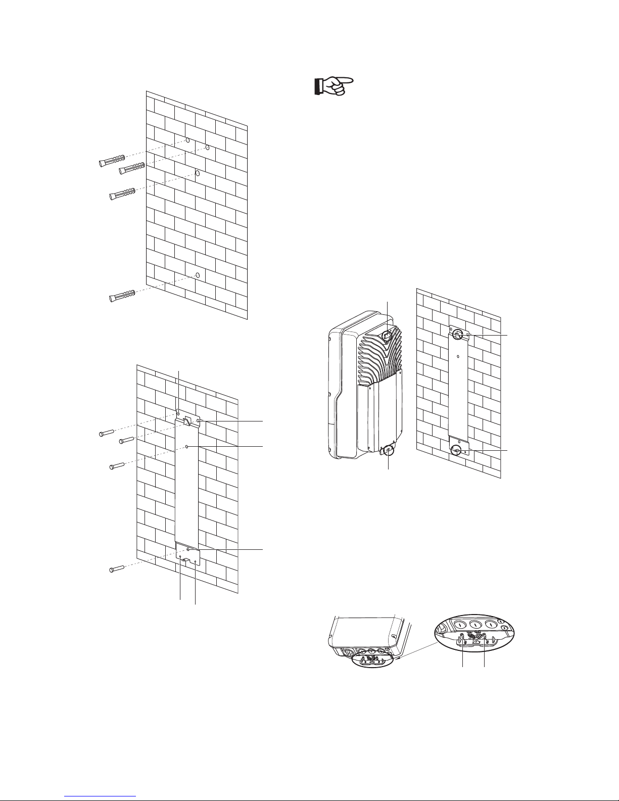
2. Clean all dust outside/inside the hole and measure pitch-row before installation. It need repositioning and drilling holes if the hole with much
error. Then put wall plug into the hole vertically
(shown in the following figures), use rubber
hammer to tap the pipe into the wall completely.
After that, mount the metal bracket to a concrete wall. The screws should be mounted in the
4 holes present in the bracket (shown as pos A in
the following figures).
Page 17
4 Mounting
17
Installation of wall plug
Installation of bracket
A
A
A
A
B
B
NOTE
The bracket needs to be mounted vertically to the
wall and the side with the hook (shown as pos C in
the next figure) should be mounted with the hook
pointing upward as shown in the figure.
3. After the bracket is secured to the wall, install
the inverter as shown in the following figure.
The inverter should be hung onto the bracket
using the hook D and the hole F that need to be
well inserted into their counterparts C and E (D
connects to C and F connects to E).
Wall mounting of inverter
C
E
D
F
4. After the inverter is hung onto the wall mounting, it needs to be secured using the M6x10
screws that will pass through the opening on the
lower side of the inverter (shown as pos H in the
following figure) into to the PEM faster (shown
as position B).
Fasten inverter installation
H
H
Page 18
4 Mounting
18
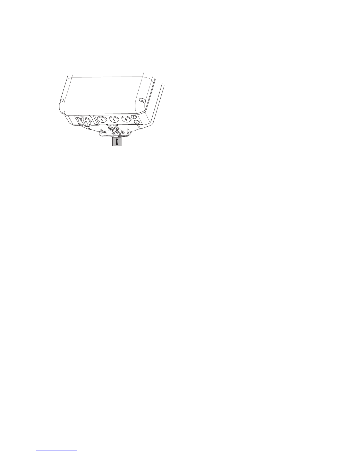
5. Lock the inverter and the bracket with lock for
safety.
Lock the inverter
6. Complete the installation process.
Page 19
5 Electrical connection
19
5 Electrical connection
WARNING
The electrical connections must be connected only
after the NTX inverter is firmly mounted to the wall.
WARNING
The connection of NTX inverter to the electrical distribution grid must be performed by qualified and
trained personnel and only after receiving authorization from the utility that operates the grid.
WARNING
For a step-by-step description of the correct procedure, please read closely and follow the instructions
provided in this section (and its subsection) and all
safety warning. Not complying with the instructions
that follow can lead to hazards and possible injury
to personnel and/or equipment damage.
WARNING
AC side field wiring should be secured away from
DC side field wiring.
WARNING
Always respect the normal ratings of voltage and
current defined in section “10 Technical data”, see
page 45 when designing your system. Please
observe these considerations in designing the PV
system:
· Maximum array DC voltage input to each MPPT
circuit: 550 V DC under any condition.
· Maximum array DC current input to each MPPT
circuit: 17.5 A DC under any condition. For NTX
6000 models, 14.5 A DC under any condition,
for NTX 5000 models, 11 A DC under any condition, for NTX 4000 models, 17.5 A DC under any
condition, for NTX 3000 models (only one MPPT
input).
WARNING
On the AC output side an AC breaker/disconnected
should be inserted between the NTX inverter and
the distribution grid. On the DC input side NTX
inverter has an optional integrated DC disconnect.
WARNING
To reduce the risk of fire, connect only to a circuit
provided with maximum branch circuit over current
protection in accordance with the National Electric
Code (ANSI/NFPA 70).
Page 20
5 Electrical connection
20
5.1 General electrical connection procedure of
NTX inverter
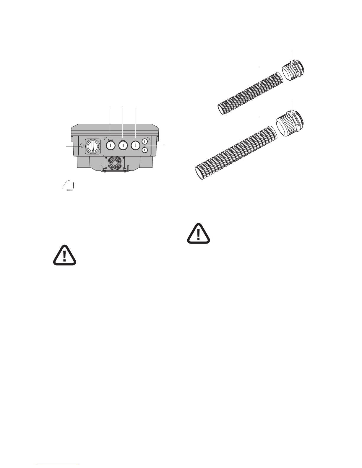
The DC input from the PV arrays and the output to
the AC utility grid connect to the inverter inside the
NTX inverter case. AC, DC and COM knockouts are
provided on the bottom of the NTX inverter.
±
DC1±DC2
AC GRID
COM
OFF
ON
1
5
2 3 4
1
OFF
ON
2 ±DC1 (DC knockouts-water tight plug size: M32)
3 ±DC2 (DC knockouts-water tight plug size: M32)
4 AC GRID (DC knockouts-water tight plug size:
M32)
5 COM (Communication knockouts-water tight
plug size: M20)
WARNING
The AC and DC knockouts are sized for 1 in. conduits, and the communication knockouts are sized
for 1/2 in. rigid conduits. Do not enlarge the knockout holes because this will result ingress of water
and damage to the inverter.
2
1
4
3
1 1/2 in. conduit
2 1/2 in. conduit fitting
3 1 in. conduit
4 1 in. conduit fitting
WARNING
In order to tighten correctly the screw terminal of
the inverter, Pin Definition applied, AWG size, temperature and torque listed in the following tables.
The restrictions on minimum AWG value are due
to cable gland. The resteictions on maximum AWG
value are due to National Electric Code (ANSI/NFPA
70).
Page 21
5 Electrical connection
21
Pin Definition
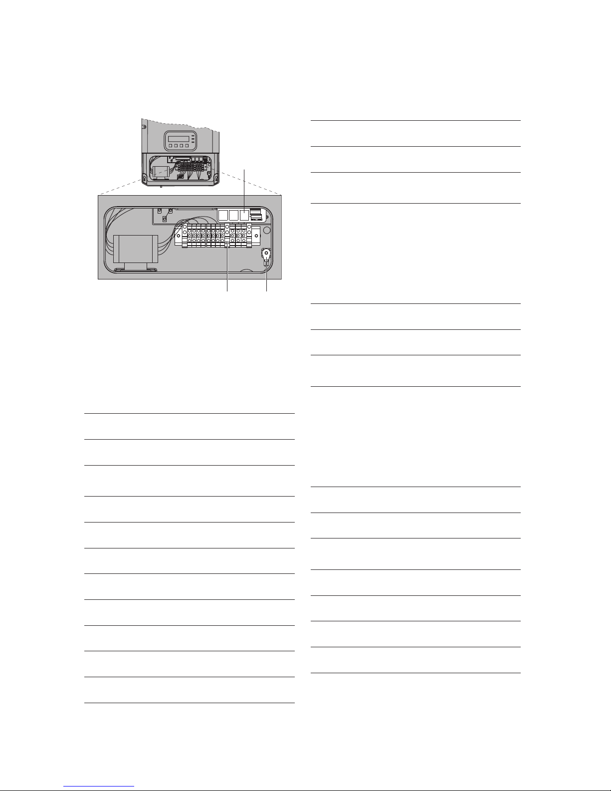
P1 and RS485 are as the following figure.
RS485Ethernet RS485 RS485
1 2 3 4 5 6 7 8 9 10 11
12
1
2 2
1 Ethernet RS485
2 P1
P1 Definition
Code Name Description
1 PV1+ MPPT1 DC1+
2 PV1+ MPPT1 DC2+
3 PV1- MPPT1 DC1-
4 PV1- MPPT1 DC2-
5 PV2+ MPPT2 DC1+
6 PV2+ MPPT2 DC2+
7
PV2-
MPPT2 DC1-
8 PV2- MPPT2 DC2-
9 3 AC 3
10 2 AC 2
11 1 AC 1
12 PE Cabinet Grounding
RS485 RJ45 Pin Definition
Code Name Description
1 1 RS 485-TX+
2 2 RS 485-TX-
3 3 RS 485-RX+
4 6 RS 485-RX-
RS485 Signal Lock Terminal Pin Definition
Code Name Description
1 1, 2 RS 485-TX+
2 3, 4 RS 485-TX-
3 7, 8 RS 485-RX+
4 9, 10 RS 485-RX-
Net RJ45 Pin Definition
Code Name Description
1 1 Ethernet NET-RX+
2 2 Ethernet NET-RX-
3 3 Ethernet NET-TX+
4 4 Ethernet CT1
5 5 Ethernet CT1
6 6 Ethernet NET-TX-
7 7 Ethernet CT2
8 8 Ethernet CT2
Page 22

5 Electrical connection
22
Models Wire size AWG
min-max
Temperature
°C
Torque
Nm In-bs
NTX 6000
AC field wiring terminals 6-8 90 1.69 15
DC field wiring terminals 8-10 90 1.69 15
Grounding Electrode 6-8 90 5.08 45
NTX 5000
AC field wiring terminals 6-8 90 1.69 15
DC field wiring terminals 8-12 90 1.69 15
Grounding Electrode 6-8 90 5.08 45
NTX 4000
AC field wiring terminals 6-10 90 1.69 15
DC field wiring terminals 8-12 90 1.69 15
Grounding Electrode 6-10 90 5.08 45
NTX 3000
AC field wiring terminals 6-10 90 1.69 15
DC field wiring terminals 8-10 90 1.69 15
Grounding Electrode 6-10 90 5.08 45
Page 23
5 Electrical connection
23
Wiring procedure of NTX inverter
1. Disconnect the inverter from the AC Grid by
opening all AC breakers/disconnects and turn the
integrated DC disconnect OFF.
2. Carefully cover all PV modules using opaque
material. Ensure that no PV module can provide
energy during this operation.
3. Opening wiring cover of wiring zone.
4. Wiring from the AC breakers/disconnects to AC
terminals of NTX inverter.
5. Wiring from the PV wires to DC terminals of NTX
inverter.
6. Connect the signal cables.
7. Turn the integrated DC disconnect ON.
8. Turn the AC breakers/disconnects ON.
NOTE
· First turn off all AC disconnects and turn the
integrated DC disconnect ‘OFF’.
· The AC side must always be disconnected before
the DC side.
· After the NTX inverter is de-energized, disconnect the wiring in the reverse order from above.
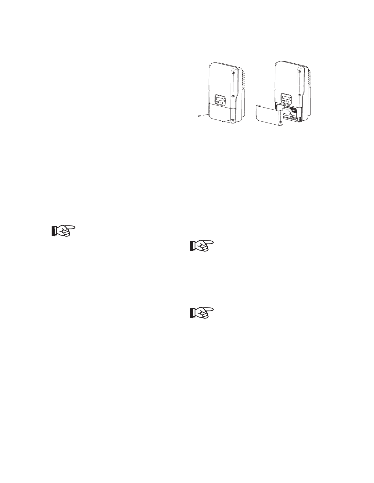
5.2 Opening wiring cover of NTX inverter
1. Remove the 2 screws from the wirng cover and
pull the cover forward smoothly.
2. Put the cover, the screws to one side so that do
not get lost.
5.3 AC wiring
This section provides complete, step-by-step procedures for wiring the AC output from the NTX
inverter to the utility.
NOTE
Overvoltage may cause cable fire.
Overcurrent protection for the AC output circuit
must be provided in the electrical installation refer
to the National Electrical Code®, ANSI/NFPA 70.
NOTE
All electrical installations must be done in accordance with the local codes and with the National
Electrical Code®, ANSI/NFPA 70. See national
National Electrical Code® section 690-64(b)(2).
The NTX comes from the factory pre-configured for
utility interconnection at Auto mode. The NTX may
be reconfigured for other utility mode by following
the steps bellow.
1. The output voltage setting is determined by the
LCD display.
Page 24
5 Electrical connection
24
2. If adjustment is necessary, choose the wire with
the correct voltage for your application and
tighten all wires on the right terminal block with
enough torque described in section “5.1 General
electrical connection procedure of NTX inverter”,
see page 20.
3. According to the below figure, set the correct
grid voltage mode.
GridMode: 240V
MPPT Input: 1
²
If the NTX is configured for the incorrect utility
voltage, the LCD will display error message.
Error: 01
Grid Volt Fault
If this error message is encountered, recheck the
output voltage configuration and confirm that it
is set property.
AC voltage configuration
The NTX may be easily configured for the different
grid types commonly found in the U.S. The NTX is
compatible with:
208 V AC output
240 V AC output
277 V AC output (only for NTX 6000)
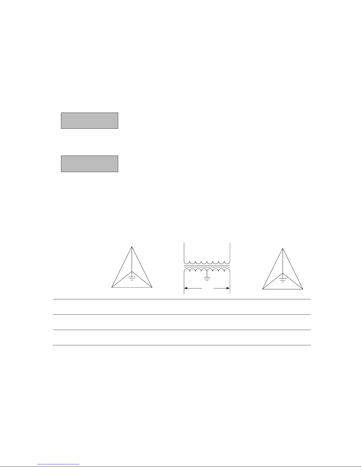
Common utility voltage configurations
The figure illustrates commonly used utility types
and connecting mode with NTX inverter.
Grid Standard
L3
L1 L2
208
N
120
120
120
208
208
L1 L2
240
120 120
L3
L1 L2
480
N
277
277
277
480
480
208~ 3PH-∆ 240~ SPLIT PHASE 277~ 3PH-Y
Terminal 3 2 1 3 2 1 3 2 1
Wire N L2 L1 N L2 L1 – L1 N
AWG# 10-12 10-12 10-12
Page 25
5 Electrical connection
25
WARNING
The NTX 3000/4000/5000 may not be connect to a
277 V grid.
If neutral(N) exists, NTX is designed to automatically detect which utility type (except for utility) it is
feeding.
The NTX may also be configured manually according
to the local utility type.
AC wiring procedure
1. Turn off the main breaker/disconnect in the main
utility breaker/disconnect box.
2. Turn the integrated DC disconnect OFF.
3. Remove interior breaker/disconnect panel cover.
4. If you are replacing an existing inverter, disconnect the wires for the AC line you are working
within the breaker/disconnect box.
5. Install a 1 in. conduit fitting on the AC Grid
knockout (the knockout on bottom of NTX
inverter). Fasten the conduit fitting on the inside
of NTX inverter with the appropriate locknut.
6. Install a 1 in. conduit between the main breaker/
disconnect box and the NTX inverter AC Grid
knockout.
7. Pull the AC wires through the conduit from the
interior of the breaker/disconnect box to the
interior of the NTX inverter.
8. Connect the AC equipment-ground wire to the
PE terminal labeled in the wiring zone of NTX
inverter.
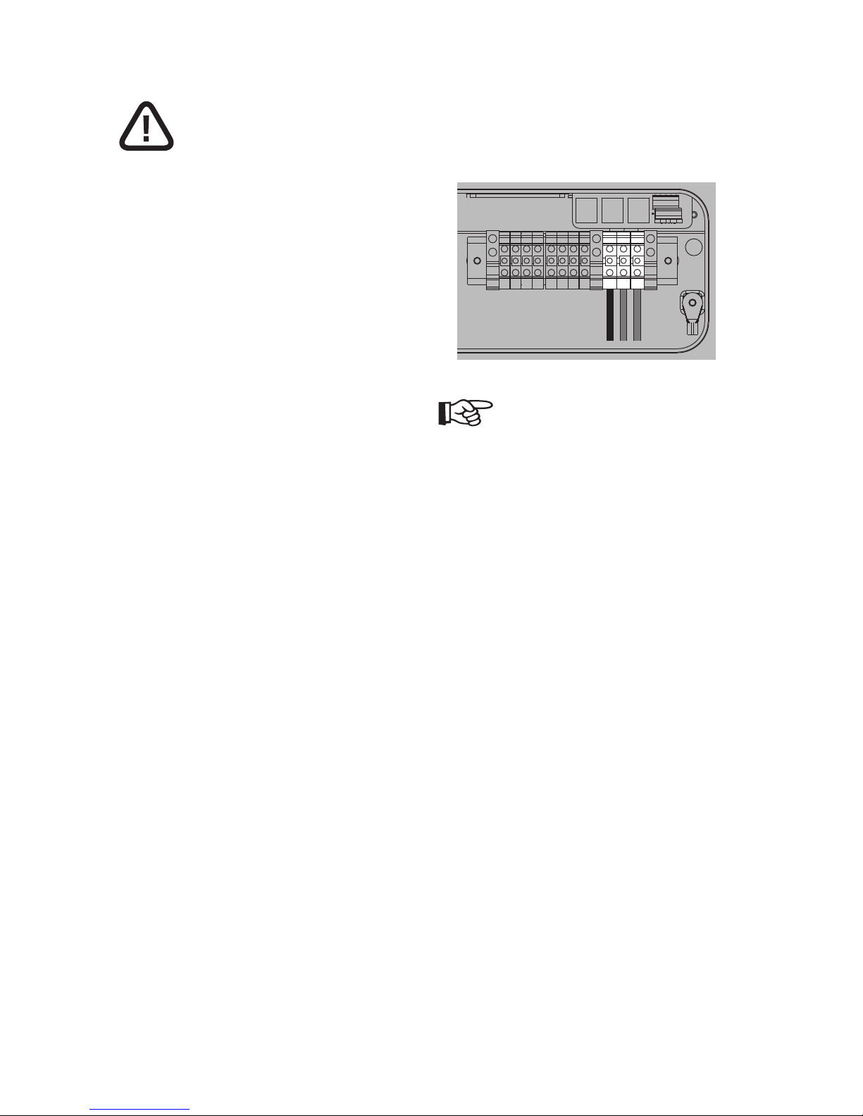
9. Connect the 3 AC wires to the relative terminal
block present inside the inverter and tighten
them. The AC wire connections should be done
based on the type of AC grid.
10. Verify that all connections are correctly wired
and properly torqued. Pull on the cable in order
to make sure that it is sufficiently fixed in the
terminal.
RS485Ethernet RS485 RS485
123
T+ T– R+ R–
NOTE
If several NTX inverters are installed in a threephase AC GRID, it is recommended to distribute the
inverters between the phases in order to reduce the
power unbalances between the phases. Always refer
to the local standards.
Page 26
5 Electrical connection
26
5.4 DC wiring
This section provides complete, step-by-step procedures for wiring the DC input from the PV array to
the NTX inverter.
WARNING
High voltage is present in PV modules exposed to
light. Death due to electric shock when touching a
DC conductor. During installation, cover all PV modules using opaque material.
WARNING
High voltage is present inside the DC cables. Death
or serious injury will result when damaging a DC
cable or touching a DC conductor. You have to connect the DC cables from the PV array to the NTX
inverter in the order described in this manual.
WARNING
The input current shall not be excecd 17.5A DC
for each input channel (NTX 6000), 14.5A DC (NTX
5000), 11A DC (NTX 4000) AND 17.5A DC (NTX 3000
have only one MPPT input).
WARNING
Verify that the DC voltage in DC terminals block has
the correct polarity and is within the operational
range.
NTX 4000/5000/6000 can be configured as an individual MPPT for each DC input channel, or configured as single MPPT for the two input DC channels
connected in parallel.
If the inverter is configured as two individual MPPTs,
the max current for each channel shall not exceed
17.5 A DC for each input channel (NTX 6000), 14.5 A
DC (NTX 5000), 11 A DC (NTX 4000).
NTX 3000 can only be configured as one MPPT and
the max current for DC input channel shall not
exceed 17.5 A DC.
Configuring the DC input channel
NTX can be configured as two individual MPPT input
channels or single MPPT input channel (parallel)
according to your application (except NTX 3000).
If DC input are configured as single MPPT input
channel (parallel), setting must be done as follows:
1. According to section “Connection to a single PV
array (NTX 4000/5000/6000)”, see page 27 or
section “Parallel Connection to 2 PV arrays
(NTX 4000/5000/6000)”, see page 28, wires are
correctly connected.
2. Turn AC breaker/disconnect OFF, then turn DC
disconnect ON.
3. According to the manual described in section
“Setting Menu”, see page 35 to configure the
MPPT input channels, and select the value of “1”.
4. Turn AC breaker/disconnect ON.
GridMode: 240V
MPPT Input: 1
²
If DC input are configured as two individual MPPT
input channels, setting must be done as follows:
1. According to section “Two MPPTS connection to
2 PV arrays or 4 PV arrays (NTX 4000/5000/6000)”,
see page 28, wires are correctly connected.
2. Turn AC breaker/disconnect OFF, then turn DC
disconnect ON.
3. According to the manual described in section
“Setting Menu”, see page 35 to configure the
MPPT input channels, and select the value of “2”.
Page 27
5 Electrical connection
27
4. Turn AC breaker/disconnect ON.
GridMode: 240V
MPPT Input: 2
²
DC wiring procedure
1. Cover all PV modules using opaque material.
2. Turn AC breaker/disconnect OFF.
3. Turn the integrated DC disconnect OFF.
4. Remove the covers on DC knockout.
5. Install two 1 in. conduit fitting in the
DC1±knockout and DC2±knockout (the knockout
in on the bottom of the NTX). Fasten the conduit
fitting on the inside of inverter with the appropriate locknut (NTX 3000 only has DC1±).
6. Install two 1 in. conduits between the PV
array and NTX inverter DC1±knockout and
DC2±knockout (NTX 3000 only has DC1±).
7. Pull the DC wires through the conduit from
inverter to the interior of the inverter
8. Connect the DC wire to DC terminal block present inside the inverter and tighten them by section “5.1 General electrical connection procedure
of NTX inverter”, see page 20. The DC connections should be done based on the type of PV
array input by section “Pin Definition”, see page
21, section “Parallel Connection to 2 PV arrays
(NTX 4000/5000/6000)”, see page 28, section
“Two MPPTS connection to 2 PV arrays or 4 PV
arrays (NTX 4000/5000/6000)”, see page 28,
section “Connection to 1 PV array or 2 PV arrays
(NTX 3000)”, see page 28.
9. Verify that all connections are correctly wired
and properly torqued. Pull on the cable in order
to make sure that it is sufficiently fixed in the
terminal.
RS485Ethernet
23
PV1+PV1+PV1–PV1–PV2+PV2+PV2–PV
2–
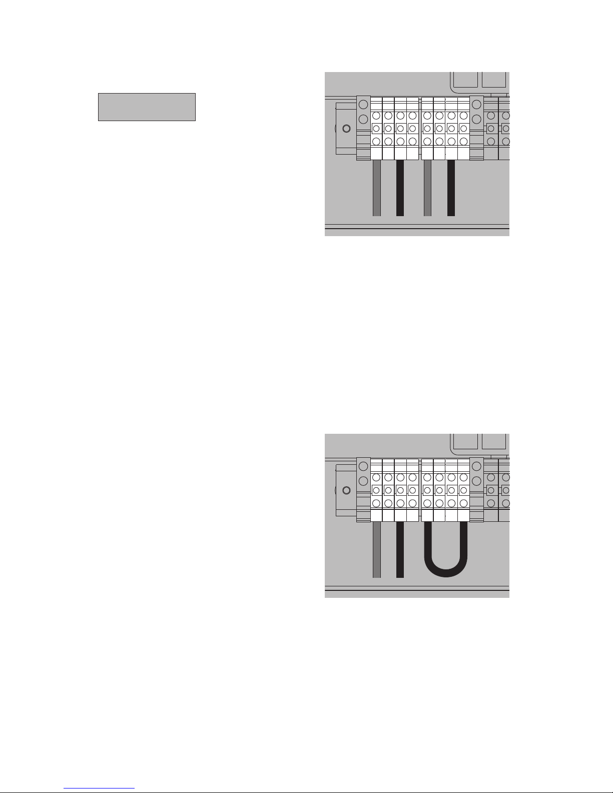
Connection to a single PV array
(NTX 4000/5000/6000)
If the system has one single PV array, and the current and the power of the array are below the limit
for the single channel, then the array can be connected to one single input channel (PV1). To avoid
possible misreadings in the insulation parameters,
we recommend using an electrical cable to short the
2 inputs of channel PV2 that are not connected to
the PV array. To short the inputs of channel PV2, use
the cable provided with the unit as shown in follow
figure.
RS485Ethernet
23
PV1+PV1+PV1–PV1–PV2+PV2+PV2–PV
2–
Page 28
5 Electrical connection
28
Parallel Connection to 2 PV arrays
(NTX 4000/5000/6000)
WARNING
When the current from the PV arrays exceeds 17.5 A
DC (NTX 6000), 14.5 A DC (NTX 5000), 11 A DC (NTX
4000), when the array power exceeds the limit for
the single channel (see table in section “10.3 Technical data”, see page 47, section “10.4 Trip limits/
trip times”, see page 48), or when there is a consistent unbalance of the power between two arrays,
it is necessary to parallel the two inputs.
When the inverter is configured with parallel input,
the current to the 2 input terminals: “PV1±” and
“PV2±” shall be equally distributed in such way to
limit to 17.5A DC (NTX 6000), 14.5A DC (NTX 5000),
11A DC (NTX 4000), the current for each terminal.
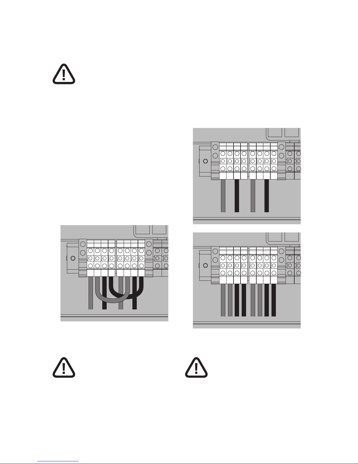
To parallel the 2 inputs, 2 AWG 10 cables should be
used to connect the terminal block PV1- and PV2-,
and PV1+ and PV2+ (1 black and 1 red cable).
RS485Ethernet
23
PV1+PV1+PV1–PV1–PV2+PV2+PV2–PV
2–
Two MPPTS connection to 2 PV arrays or 4 PV arrays
(NTX 4000/5000/6000)
WARNING
If the inverter configured as two individual MPPTs
connect to two PV arrays, the max current for PV
array shall not exceed 17.5 A DC for each input
channel (NTX 6000), 14.5 A DC (NTX 5000), 11 A DC
(NTX 4000).
If the inverter configured as two individual MPPTs
connect to 4 PV arrays, the max total current for PV
arrays connect terminals “PV1±” or “PV2±” shall not
be exceed 17.5 A DC for each input channel (NTX
6000), 14.5 A DC (NTX 5000), 11 A DC (NTX 4000).
When connect to 2 PV arrays, one array connect
to one pair of terminals “PV1±” and other pair of
terminal “PV1±” should be free. The second array
connect to one pair of terminals “PV2±” and other
pair of terminal “PV2±” should be free.
RS485Ethernet
23
PV1+PV1+PV1–PV1–PV2+PV2+PV2–PV
2–
RS485Ethernet
23
PV1+PV1+PV1–PV1–PV2+PV2+PV2–PV
2–
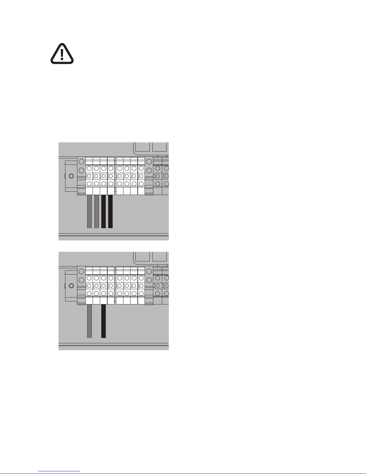
Connection to 1 PV array or 2 PV arrays (NTX 3000)
WARNING
If the inverter connect to 1 PV arrays, the max current for PV arrays shall not be exceed 17.5 A DC for
the single input channel (NTX 3000).
Page 29
5 Electrical connection
29
WARNING
If the inverter connect to 2 PV arrays, the max total
current for PV arrays connect terminals “PV1±” shall
not be exceed 17.5 A DC for the single input channel
(NTX 3000).
When connected to 1 PV array, the array connect
to one pair of terminals “PV1±”and other pair of
terminal “PV1±” should be free.
RS485Ethernet
23
PV1+PV1+PV1–PV1–PV2+PV2+PV2–PV
2–
RS485Ethernet
23
PV1+PV1+PV1–PV1–PV2+PV2+PV2–PV
2–
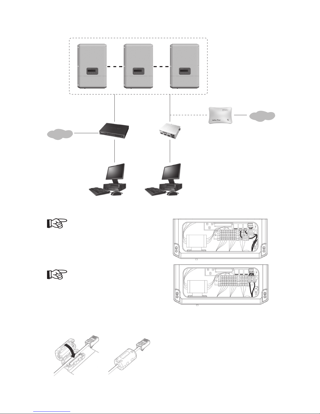
5.5 Communication wiring
1. Remove the covers on RS485 and Ethernet
knockouts.
2. Install two 1/2 in. conduit fitting in the RS485
and Ethernet knockouts (the knockout on the
bottom of the NTX inverter). Fasten the conduit
fitting on the inside of inverter with the appropriate locknut.
3. Lay down the RS485 cables between NTX inverter
and other NTX inverter, lay down Ethernet cables
between NTX inverter and Hub or router.
4. Insert the single cable into RS485 and Ethernet
ports.
5. Bunding the signal cable onto the cable holder
of wiring box.
Page 30
5 Electrical connection
30
Router
RS485
adapter
RS232
SolaPower
Manager
Ethernet
Ethernet
NOTE
The RJ485 pin definition refer to section “5.1
General electrical connection procedure of NTX
inverter”, see page 20.
NOTE
When using a third-party RS485 cables to connect
the inverters, attach the supplied ferrite cores to the
RS485 cables as shown. NTX supply two ways to connect RS485, one way is using RS485 cables with RJ45
connectors to insert into RS485 blocks, another way
is screwing RS485 cables on terminal blocks.
10 cm or less
Page 31
6 Commissioning
31
6 Commissioning
All NTX inverters require that PV array normally
operates in an ungrounded configuration. As
required by UL 1741 update, the GFCI protection
is active whenever there is sufficient DC voltage to
feed PV power into the utility grid in the NTX.
DANGER
Deviating from the procedure described in this
chapter could expose you to lethal voltages. Death
or serious injury will result.
Commission the NTX in the order described in the
following procedure.
1. Make sure any covering placed over the PV array
is removed.
2. Connect the grid voltage to the NTX by turning
on the main AC circuit breaker/disconnect in the
main utility panel.
3. Turn the external DC disconnect to position
“ON”.
Or
Turn the NTX internal DC disconnect to the “ON”
position.
4. If there is sufficient sunlight available, the NTX
will enter the “Waiting” mode and the green
LED will stay on steady during the system check
routine.
5. If no AC fault is detected, the NTX will enter the
“Checking” mode, and the NTX will begin to
run normally. At the same time the green LED
will keep flashing and the LCD enter the default
menu. If an AC fault was detected, the NTX will
wait five minutes prior to starting.
WARNING
If there is a ground fault in the array, the message
“GFCI Fault” will be displayed. If this messege is
encountered, turn off the DC and AC disconnects to
the inverter and trouleshoot the array.
The NTX will automatically begin to feed power to
the utility grid if there is adequate solar irradiation
and the resulting PV input voltage is greater than
150 V DC.
If the NTX is not operating as expected after commissioning has been completed, refer to section “7
Display and messages”, see page 32 and to section
“8 Troubleshooting”, see page 40.
WARNING
· Anytime the AC power is disconnected from
the inverter either manually or as a result of an
AC disturbance, the inverter will wait 5 minutes after the AC power has been restored to
reconnect.
· When servicing the inverter, always disconnect
the AC first, then the DC.
Page 32
7 Display and messages
32
7 Display and messages
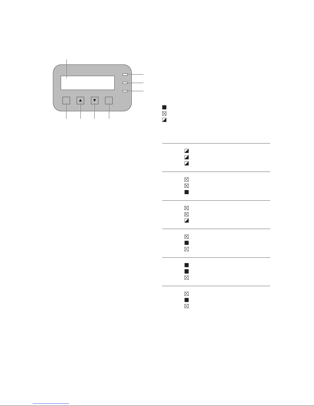
2
3
4
5 6 7 8
Welcome to use
NTX 5000
GFCI
Alarm/fault
Normal
ESC
OK
1
1 Display
2 GFCI
3 Alarm/Fault
4 Normal
5 ESC
6 UP
7 DOWN
8 OK
7.1 LED indicators
There are four LEDs at the side of the display: the
first LED from the top (GFCI) indicates a ground
fault, the second LED (Fault/Alarm) indicates a fault
or alarm condition, the third LED (Normal) indicates
proper operation of the inverter.
· The red “GFCI” (ground fault) LED indicates that
inverter is detecting a ground fault in the DC
side of the photovoltaic system. When this kind
of fault is detected, the red LED keeps flashing
and the inverter immediately disconnects from
the grid and the corresponding fault indication
appears on the display.
· The double color “Fault/Alarm” LED indicates
that the inverter has detected a fault or alarm
condition. If the alarm condition detected, the
yellow LED keeps flashing until the inverter go to
the normal state. If the fault condition detected,
the red LED keeps flashing until the inverter go
to the normal state. When the Fault/Alarm state
appeared, a Fault/Alarm description will appear
on the display.
· The green “Normal” LED indicates that the NTX
inverter is operating correctly. This LED stays on
steady upon start-up, during the system check
routine. If the system is all right, the system will
go to the running state. In this condition, the
LED keeps flashing.
LED indicator combinations and their meaning are
listed in the following table.
Key:
LED on
LED flashing
LED off
LEDs
Status
Operational
Status
Remarks
1 red:
red:
green:
Start-up The three LEDs will
flash 5 times.
2 red:
red:
green:
Waiting
or
Checking
3 red:
red:
green:
Running
4 red:
red:
green:
Fault
5 red:
red:
green:
GFCI Fault
6 red:
red:
green:
Alarm
Page 33

7 Display and messages
33
7.2 Available Data
The NTX inverter provides two types of data that
can be collected using the NTX Communicator interface software.
Real-time operational data
Real-time operational data can be transmitted on
demand through the communication and display on
LCD. They are not stored by inverter. The NTX communicator software (available on the installation
CD) may be used to transmit data to PC.
The following data is available:
· Grid voltage
· Grid current
· Grid frequency
· Power transferred to the grid
· Voltage of photovoltaic array 1
· Current of photovoltaic array 1
· Voltage of photovoltaic array 2
· Current of photovoltaic array 2
· Serial number/Part number
· Firmware revision code
· Daily energy
· Monthly energy
· Total energy
· Leakage current to ground
· Date, time
Internally logged data
The NTX inverter stores internally the following data
you can query through LCD or PC monitor software.
· Today’s lifetime counter of energy transferred to
the grid.
· This month’s lifetime counter of energy transferred to the grid.
· Total lifetime counter of energy transferred to
the grid.
· Last 50 fault conditions with error code and time
stamp.
· Last 50 start and stop time of energy transferred
to the grid.
7.3 LCD display and operation
The two-line Liquid Crystal Display is located on the
front panel and shows:
· Inverter operating status and statistics,
· Service messages for the operator,
· Error messages and fault indications.
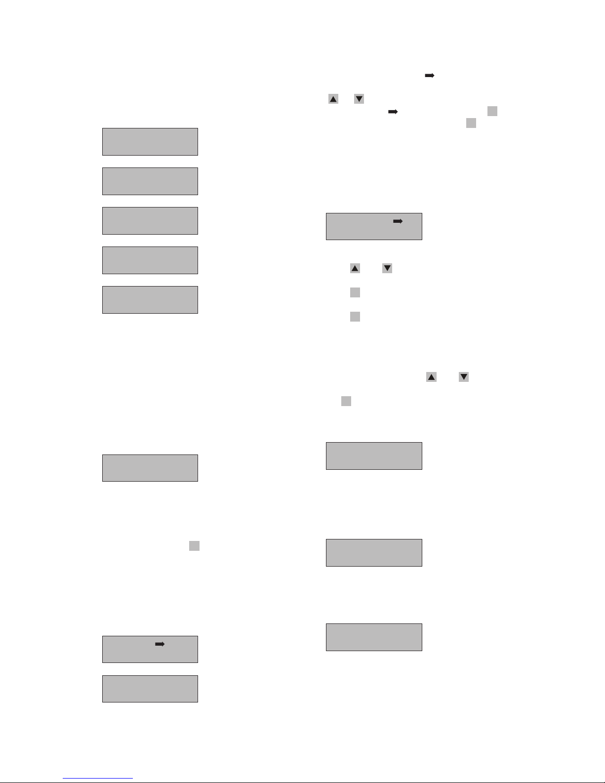
Display upon start-up
During normal conditions, the LCD backlight will be
turn on first upon start-up, and the backlight shuts
off automatically after 1 minutes.
The following messages are displayed during initialization of the inverter:
1. Starting up (remain 5 seconds)
Welcome to use
Sunways Inverter
2. Waiting
After starting up the system go to waiting state,
and the LCD will display following 5 screens messages in turn.
Welcome to use
Sunways Inverter
Waiting
Waiting Sun
Waiting.
Waiting Sun
Welcome to use
Sunways Inverter
Waiting.
Waiting Sun
Waiting.
Waiting Sun
Welcome to use
Sunways Inverter
Waiting..
Waiting Sun
Waiting.
Waiting Sun
Welcome to use
Sunways Inverter
Waiting...
Waiting Sun
Waiting....
Waiting Sun
The display changes to next screen every half
second.
Page 34
7 Display and messages
34
3. Checking
When the inverter turn to the checking state
from waiting state, the LCD will display following 5 screens messages in turn.
Welcome to use
Sunways Inverter
Checking.
Please Wait
Waiting.
Waiting Sun
Welcome to use
Sunways Inverter
Checking..
Please Wait
Waiting.
Waiting Sun
Welcome to use
Sunways Inverter
Checking...
Please Wait
Waiting.
Waiting Sun
Welcome to use
Sunways Inverter
Checking....
Please Wait
Checking.....
Please Wait
The display changes to next screen every half
second.
Default Menu
During normal condition, the inverter will turn to
the running state after the checking state, and the
LCD will display Default Menu.
P-out:0000 W
E-day:000.0 KWh
The screen messages indicate output power now
and daily energy output.
At the default menu you can turn to the main menu
manually by pressing the
ESC
-key.
Main Menu
The main menu has two screens messages and four
options.
Running
Settings
Event
Service
The line of LCD has the icon means your option.
You can choose your option manually by pressing
the
- or -key. If you want enter the option
which has the icon
at the right, press the OK-key;
If you want quit Main Menu, press the
ESC
-key, and
LCD will turn to the default menu.
Running Menu
The Running Menu has two submenus:
Information
Statistics
Press the - and -key to scroll through items.
Press the
ESC
-key to go back to the previous menu.
Press the
OK
-key to open the selected submenu.
1. Information
This submenu mainly contains some running
data of the inverter. The screens may be scrolled
manually by pressing the
- and -keys. And
you can call back the previous menu by pressing
the
ESC
-key.
1
Vin1: 000 V
lin1: 00.0 A
Vin1: Input voltage at channel 1
Lin1: Input current at channel 1
2
Vin2: 000 V
lin2: 00.0 A
Vin2: Input voltage at channel 2
Lin2: Input current at channel 2
or
Vin: 000 V
lin: 00.0 A
In a configuration with one input connected and
a second input connected in parallel, this screen
is shown instead of the 2 screens described in 1
and 2.
Page 35
7 Display and messages
35
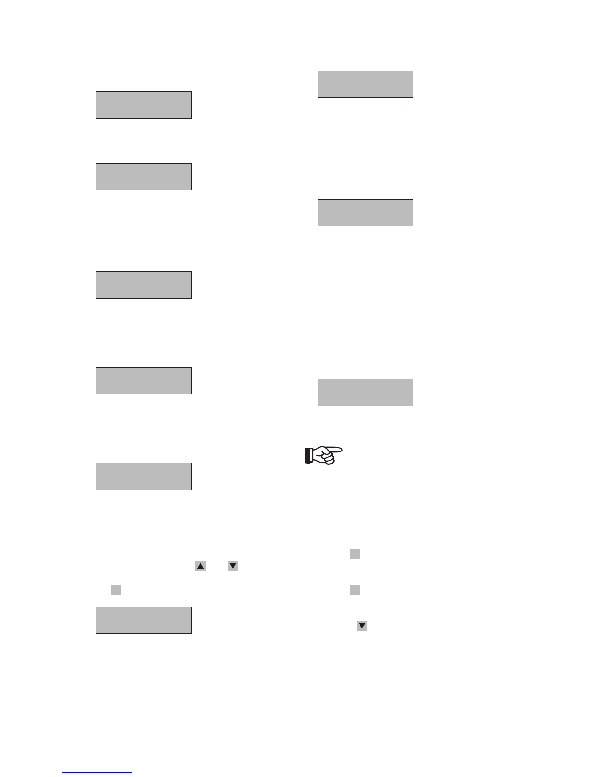
3
Pin1:0000 W
Pin2:0000 W
Pin1: Input power of channel 1
Pin2: Input power of channel 2
Pin:0000 W
In a configuration with one input connected and
a second input connected in parallel, this screen
is shown instead of the screen described in 3.
4
Vgrid: 000 V
Igrid: 00.0 A
Vgrid: Grid voltage
Lgrid: Grid current
5
Pout:0000 W
Fgrid:000.0 Hz
P-out: Output power
Fgrid: Grid frequency
6
GFCI: 0000 mA
GFCI: Leakage current of the system
2. Statistics
This submenu mainly contains some Statistics
data of the inverter. The screens may be scrolled
manually by pressing the
- and -keys. And
you can call back the previous menu by pressing
the
ESC
-key.
T-day:000.0 h
E-day:000.0 KWh
T-day:
Today’s lifetime counter of energy transferred to
the grid.
E-day: Today’s energy transferred to the grid.
T-mon:000.0 h
E-mon:000.0 KWh
T-mon:
This month’s lifetime counter of energy transferred to the grid.
E-mon:
This month’s energy transferred to the grid.
T-tot:000.0 h
E-tot:000.0 KWh
T-tot:
Total lifetime counter of energy transferred to
the grid.
E-tot: Total energy transferred to the grid.
Setting Menu
Select “Settings” from the Main menu to display the
first screen that refers to the password:
Password
0000
Default password is “0000”.
NOTE
Can’t enter settings menu when communication is
abnormal. Running state no setting allowed.
Operation guide
· Use the
OK
-key to move from one figure to the
next (from left to right)
· Use the
ESC
-key to go back to quit password input
and go back to the previous menus.
· Press the
-key to scroll numbers backwards
(from 0 to 9).
Page 36
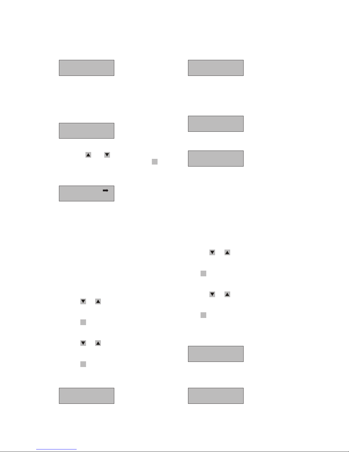
7 Display and messages
36
· If the password is wrong, the LCD will give the
message:
Incorrect!
Input again!
And then turn to the password input screen
again. If the password is right, LCD will enter settings submenu. At the same time the system will
query settings parameter, if query loss the LCD
will give the message:
Query Lose!
Please check it!
This submenu may be scrolled manually by pressing the the
- and -keys. And you can call
back the previous menu by pressing the
ESC
-key.
1
GridMode: 240V
MPPT Input: 1
If the neutral doesn’t exist, the NTX inverter
software can’t automatically detect which grid
voltage it is feeding and how many MPPT input
it has. So you need to configure manually it.
Grid mode:
Which grid voltage it is feeding. 240 V, 208 V,
277 V or Auto.
MPPT input: How many MPPT input. 1 or 2.
Operation guide
· Press the
- or -key to scroll screen and select
your submenu.
· Press the
OK
-key enter the setting mode which
you selected.
· Press the
- or -key to scroll screen and select
your parameter.
· Press the
OK
-key to confirm your selection. If your
selection become operative, the LCD will give the
message:
Setting OK !
Or else, the LCD will give the message, and your
selection will retain the previous setting.
Setting Lose!
Please check it!
Press ESC key to quit and go back to the previous
menus.
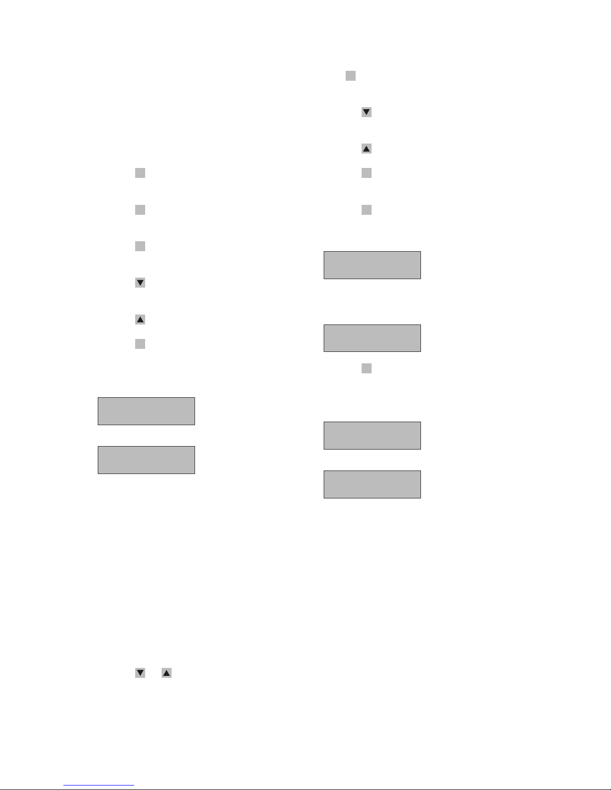
2
Restart
New Password
or
Shutdown
New Password
The NTX inverter can be Restart or Shutdown
when the inverter need be done.
Restart:
The NTX inverter stops current state and turn to
the system check routine again.
Shutdown:
The NTX inverter stops current state and do not
turn to the system check routine again.
· Press the
- or -key to scroll screen and select
your submenu.
· Press
OK
-key to enter the setting mode which you
selected.
· Press the
- or -key to scroll screen and select
your parameter.
· Press
OK
-key to confirm your selection. (Restart
and Shutdown need input password to confirm)
If your selection become operative, the LCD will
give the message:
Setting OK !
Or else, the LCD will give the message, and your
selection will retain the previous setting.
Setting Lose!
Please check it!
Page 37
7 Display and messages
37
New Password:
This function is used to change the default password 0000.
To set your personal code, use the display keys as
follows:
· Press the
OK
-key to move from one digit to the
next (from left to right).
· Press the
ESC
-key to go back to the previous digit
(from left to right).
· Press the
ESC
-key repeatedly to go back to the
previous menus.
· Press the
-key to scroll numbers backwards
(from 9 to 0).
· Press the
-key to scroll numbers from 0 to 9.
Press the
ESC
-key to quit and go back to the previ-
ous menus.
3
Tvh1:0000ms
Tvl1:0000ms
Tvh2:0000ms
Tvl2:0000ms
The NTX inverter’s grid voltage protect time is
adjustable. The grid voltage protect time has
four valid limits.
Tvh1: very high grid voltage protect time.
Tvl1: very low grid voltage protect time.
Tvh2: high grid voltage protect time.
Tvl2: high grid voltage protect time.
Range:
9960≥Tvl2≥83; 9960≥Tvh2≥83;
498≥Tvh1≥83; 498≥Tvl1≥83.
Operation guide
· Press the
- or -key to scroll screen and select
your submenu.
· Press
OK
-key to enter the setting mode which you
selected.
· Press the
-key to scroll numbers backwards
(from 9 to 0).
· Press the
-key to scroll numbers from 0 to 9.
· Press the
OK
-key to move from one digit to the
next (from left to right).
· Press the
OK
-key to confirm your input. (When it
is the last one). If your selection becomes operative, the LCD will give the message:
Setting OK !
Or else, the LCD will give the message, and your
selection will retain the previous setting.
Setting Lose!
Please check it!
Press the
ESC
-key to quit and go back to the previous menus.
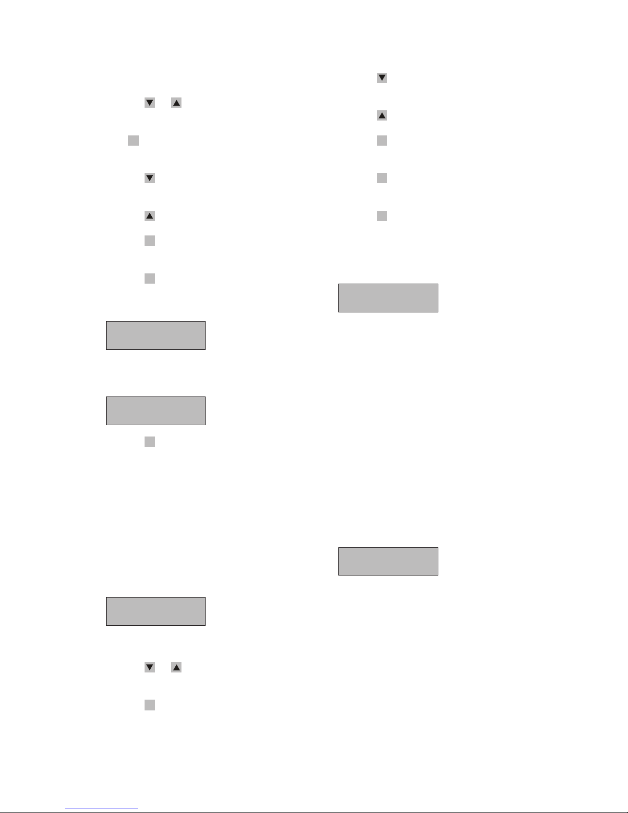
4
Vhtp1:000%
Vltp1:000%
Vhtp2:000%
Vltp2:000%
The NTX inverter’s grid voltage trip point is
adjustable. The grid voltage trip point has four
valid limits.
Vhtp1: very high grid voltage trip point.
Vltp1: very low grid voltage trip point.
Vhtp2: high grid voltage trip point.
Vltp2: high grid voltage trip point.
Range:
120≥Vhtp1≥105
95≥Vltp1≥50
115≥Vhtp2≥105
95≥Vltp2≥55
Vhtp1≥Vhtp2≥Vltp2≥Vltp1
Page 38
7 Display and messages
38
Operation guide
· Press the
- or -key to scroll screen and select
your submenu.
· Press
OK
-key to enter the setting mode which you
selected.
· Press the
-key to scroll numbers backwards
(from 9 to 0).
· Press the
-key to scroll numbers from 0 to 9.
· Press the
OK
-key to move from one digit to the
next (from left to right).
· Press the
OK
-key to confirm your input. (When it
is the last one). If your selection becomes operative, the LCD will give the message:
Setting OK !
Or else, the LCD will give the message, and your
selection will retain the previous setting.
Setting Lose!
Please check it!
Press the
ESC
-key to quit and go back to the previous menus.
5
The NTX inverter provided a RTC for recording
some data or events. Such as statistic and error
log, so the RTC’s accuracy is the internally logged
data. The time can be shown at default menu
and settings menu. When you find the data and
time is incorrect, you should enter settings menu
and correct it.
Date: 31-12-2000
Time: 00:00:00
Operation guide
· Press the
- or -key to scroll screen and select
your submenu.
· Press the
OK
-key to enter the setting mode which
you selected.
· Press the
-key to scroll numbers backwards
(from 9 to 0).
· Press the
-key to scroll numbers from 0 to 9.
· Press the
OK
-key to move from one digit to the
next (from left to right).
· Press the
OK
-key to confirm your input. (When it
is the last one).
· Press the
ESC
-key to quit and go back to the
previous menus. You should ensure legitimacy of
time.
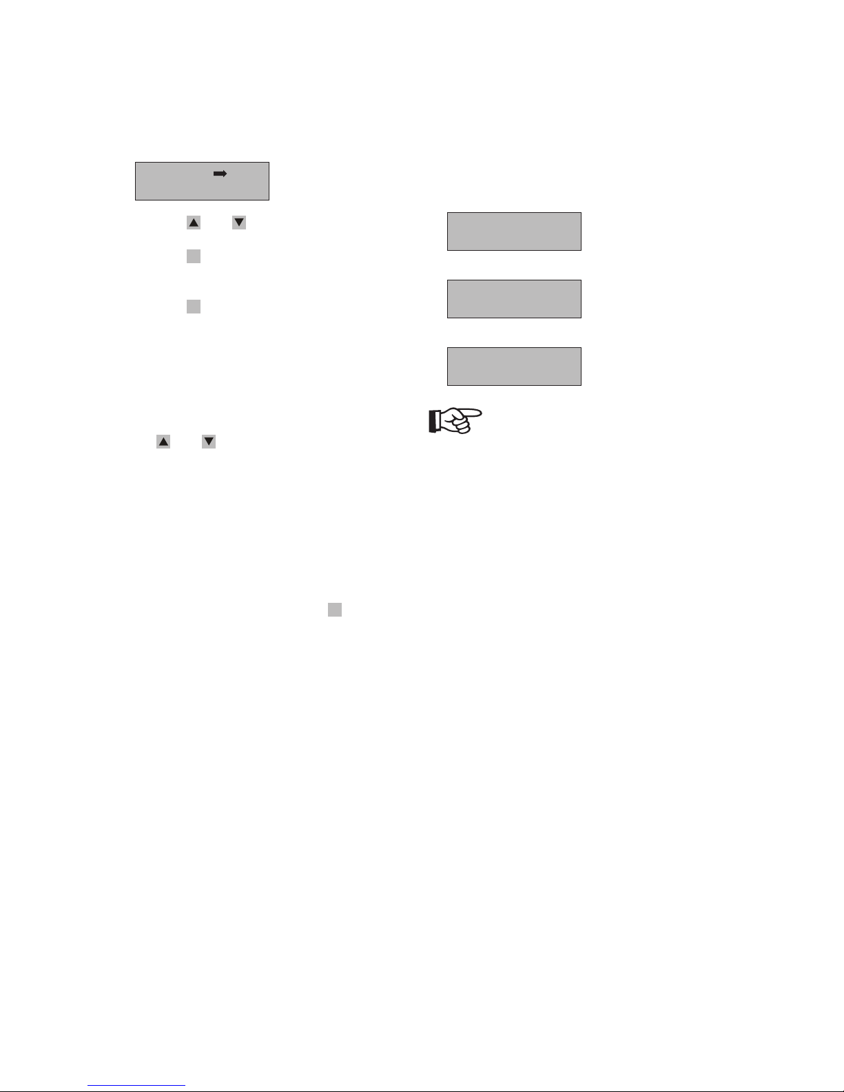
6
Tfl:100.00s
Fl:059.0Hz
Tfl: low frequency protect time.
Fl: low frequency.
Range:
300s≥Tfl≥0.16s
59.8Hz≥Fl≥57.0Hz
7
The NTX inverter provides “Ethernet monitor”
function. The factory defaults:
IP 192.168.1.2
Gateway 192.168.1.1
SubnetMask 255.255.255.0
User can modify or look at them through the
local LCD.
192.168.001.002
192.168.001.001
The first line is IP address and the second
line is Gateway. The SubnetMask is fixed at
255.255.255.0.
User can enter setting mode in this interface,
the setting method is analogous to time setting.
Prompt “setting OK” and “Restart Power Please
!” after setting.
Page 39
7 Display and messages
39
Event
The Event Menu has two submenus:
Error Log
Operation Log
· Press the - and -keys to scroll through items.
· Press the
ESC
-key to go back to the previous
menu.
· Press the
OK
-key to open the selected submenu.
1. Error Log
This submenu is some error logs of inverter. You
can query 50 fault conditions with error code
and time stamp.
The screens may be scrolled manually by pressing
the
- and -keys. And you can call back the
previous menu by pressing the ESC key.
2. Operation Log
This submenu is some part and stop time logs of
the inverter. You can query last 50 start and stop
time of energy transferred to the grid.
The screens may be scrolled manually by pressing
the UP and DOWN keys. And you can call back
the previous menu by pressing the
ESC
-key.
Service
The service Menu contains some system info, such as
serial number, hardware version number, software
version number and contacts about Sunways. The
screens messages as follow:
DSP Ver:00.00
ARM Ver:00.00
S/N:***********
See manual
NOTE
Instruction about software modification and
upgrading refers to CD attached.
Page 40
8 Troubleshooting
40
8 Troubleshooting
8.1 General
We assure that each inverter is manufactured to
exact specifications and is thoroughly tested before
leaving the factory. If you encounter difficulty with
the operation of your inverter, please follow the
steps below in an effort to correct the problem.
· Check the LED indicator combinations on the
panel of the NTX inverter.
· Check and record the “ERROR” messages on the
LCD display or other. Take appropriate action to
correct the issue.
NOTE
When the inverter is in error, the error information
is composed of “error code+time” displayed on LCD,
as the following:
01: Volt Fault
11-03 15:30:30
· If necessary, check the DC and AC voltages at
terminals inside the inverter. Be sure to observe
all of the safety precautions listed throughout
this manual when doing so, or hire a qualified
professional.
· If the system problem persists, contact Sunways
technical support at:
Tel: 49(0) 753199677-0.
Email: [email protected]
In order to better assist you when contacting Sunways, please provide the following information. This
information is required for service assistance.
Information regarding the NTX:
· Serial number
· Model
· Brief of the problem
· LED indicator combinations or display message
· What error code is indicated? (Provided a communication option is installed)
· AC voltage
· DC voltage
· Can you reproduce the failure? If yes, how?
· Has this problem occurred in the past?
· What were the ambient conditions when the
problem occurred?
Information regarding the PV modules:
· Manufacturer name and model of the PV module
· Output power of the module
· Open circuit voltage (Voc) of the module
· Number of module in each string
If it becomes necessary to send the NTX inverter
back to the manufacturer for service, please ship
it in the original box to avoid damage during
shipping.
Page 41
8 Troubleshooting
41
8.2 Messages and Error Codes
The system status is identified through message or
error codes appearing on the LCD. When the system
appears error status, the LCD will show corresponding message. The table that follows summarizes the
messages that can be displayed.
Message Code Description Solutions
Grid Volt Fault 01 Grid Overvoltage or
Undervoltage
· Check whether AC grid(voltage and
frequency) is beyond the scope;
· Check whether the connection of AC
side is correct;
Grid Freq Fault 02 Grid Over frequency or Under
frequency
PV1 Volt Fault 03 PV1 Input Under voltage or
Over voltage
· Check whether the output voltage of
PV array is in the allowing range.
· Check whether the insulation of PV
cable is good;
· Inspect whether the installation is
correct according to the manual.
· If still at fault, please ask for help.
PV1 Cur Fault 04 PV1 Input Over current
PV2 Volt Fault 05 PV2 Input Under voltage or
Over voltage
PV1 Cur Fault 06 PV2 Input Over current
GFCI 300mA 07 Ground leakage over 300mA
GFCI 30mA 08 Ground leakage jump over
30 mA
GFCI 60mA 09 Ground leakage jump over
60 mA
GFCI 150mA 10 Ground leakage jump over
150 mA
Relay Fault 11 Relay abnormity Ask for help if still at fault after
rebooting.
Page 42
8 Troubleshooting
42
Message Code Description Solutions
No Utility 12 Missing Grid
· Check whether AC grid(voltage and
frequency) is beyond the scope;
· Check whether the connection of AC
side is correct;
· If still at fault, please ask for help.
Comm loss 13 Communication abnormity Ask for help if still at fault after
rebooting.
Temp Fault 14 Temperature too high or low Ask for help.
Fan Fault 15 Fan abnormity (Warning) Check the fan. If not turn, contact to
exchange.
ISO Fault 16 ISO abnormity · Check whether the output voltage of
PV array is in the allowing range.
· Check whether the insulation of PV
cable is good;
· Inspect whether the installation is
correct according to the manual.
· If still at fault, please ask for help.
Unknown grid 17 Report unknown grid fault
when failing to detect
Ask for help.
EEPROM Fault 18 EEPROM read or write loss Ask for help if still at fault after
rebooting.
DCI Fault 19 DCI over limit Ask for help.
Short Circuit 20 Output Short Circuit Ask for help.
Over Load 21 Inverter over load (Warning) Ask for help.
Output OCP 22 Output Over current Ask for help.
23 GFCI Hard Fault Ask for help.
Page 43

8 Troubleshooting
43
Message Code Description Solutions
DC Reverse 24 DC Reverse · Check whether the output voltage of
PV array is in the allowing range.
· Check whether the insulation of PV
cable is good;
· Inspect whether the installation is
correct according to the manual.
· If still at fault, please ask for help.
System Fault 25 System Fault Ask for help.
PV1 Always low 26 (Warning) Check PV1 array.
PV2 Always low 27 (Warning) Check PV2 array.
Bus OVP 28 Bus OVP Ask for help.
Page 44
9 Maintenance
44
9 Maintenance
The NTX is designed to provide many years of trouble-free service. Performing regular maintenance
will help ensure the long life and high efficiency of
your system.
9.1 Cleaning the fans
The fan intake should be cleaned periodically with
a vacuum cleaner. (Do not blow air into the fan
area) for deeper cleanings, the fan can be removed
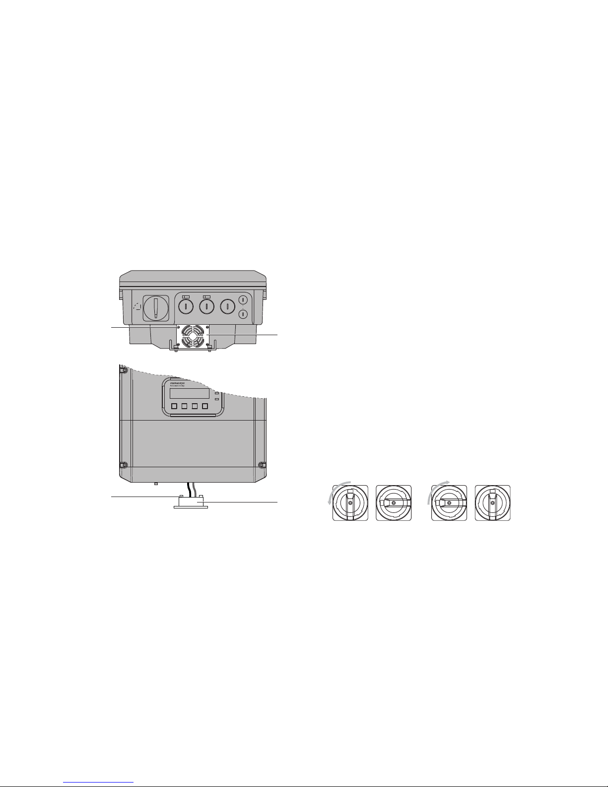
completely. The NTX is fitted with one fan on its
underside.
±
DC1±DC2
AC GRID
COM
OFF
ON
1
2
4
3
1 Screws
2 Fan screen
3 Nuts
4 Fan
In order to clean the fan, proceed as follows:
1. Turn off all DC and AC breaker/disconnects and
wait for 5 minutes for any residual voltages to
dissipate.
2. Disconnect the NTX from both the DC and AC
connections.
3. Wait for the fan to stop rotating.
4. Screw up 4 screws on the fan screen and remove
it carefully because the fan mounted behind and
the cables are not so long.
5. The fans are fastened with 4 nuts, remove them
to separate the fan screen and the fan. Then you
can clean the fan screen and the fan separately.
6. To clean the fan, use a soft brush or cloth. Do not
use air pressure for clean the fan. This will damage the fan.
7. When the fan is clean, reinstall it using the above
steps in reverse order.
8. Do not blow air through the fan or fan screen
while the fan plate is assembled on the NTX.
9.2 Checking the DC Disconnect
Under normal use condition, the DC Disconnect does
not need maintenance.
It is recommended to:
· Check the DC Disconnect regularly.
· Operate the DC Disconnect 12 times once a year.
Operating the switch will clean the contacts and will
extend the life of the DC Disconnect.
Page 45

10 Technical data
45
10 Technical data
10.1 FCC compliance information
Sunways photovoltaic grid-connected inverter,
model NTX complies with part 15 of the FCC rules.
Operation is subject to the following conditions.
· This device may not cause harmful interference.
· This device must accept any interference
received, including interface that may cause
undesired operation.
NOTE
This equipment has been tested and found to comply with the limits for a Class A & B digital device,
pursuant to Part 15 of the FCC rules. These limits are
designed to provide reasonable protection against
harmful interference in a residential installation.
This equipment must be installed and used in accordance with the instructions, or it may cause harmful
interference to radio communications. However,
there is no guarantee that interference will not
occur in a particular installation. If this equipment
does cause harmful interference to radio or television reception, which can be determined by turning
the equipment off and on, the user is encouraged to
try to correct the interference by one or more of the
following measures:
· Reorient or relocate the receiving antenna.
· Increase the separation between the equipment
and the inverter.
· Connect the equipment into an outlet on a
circuit different from that to which the receiver
is connected.
· Consult the dealer or an experienced radio/TV
technician for help.
· The user is cautioned that changes or modifications not expressly approved by Sunways
could void the user’s authority to operate this
equipment.
Page 46
10 Technical data
46
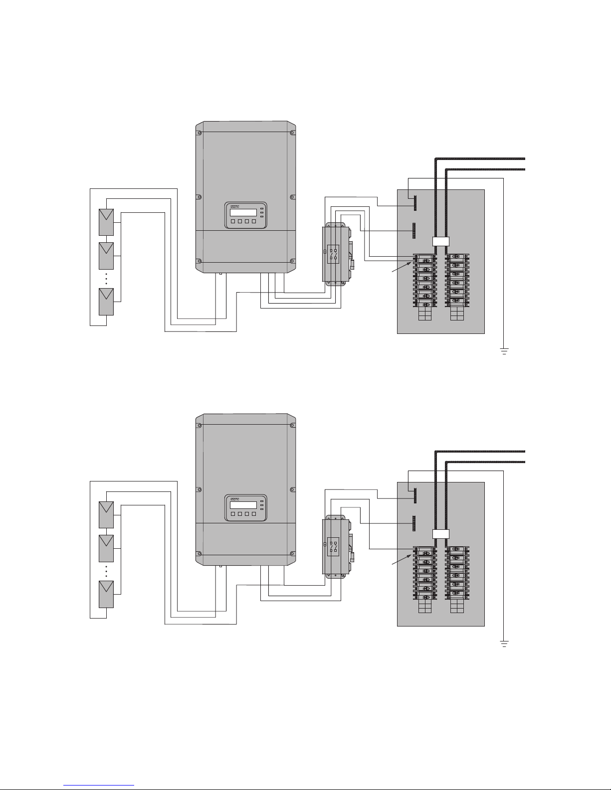
10.2 NTX wiring diagrams
NTX connections for 208 V and 240 V AC grids
AC Switch
PV
Array
Equipment
Ground
PV+
PV–
PV+
PV–
N
L1 L2 PE
OFF
Breaker
Size
2p 50 Amp
AC
Distribution
Panel
Earth Ground
Utility
ON
L1 L2
Main
Ground
Neutral
NTX connections for 277 V AC grids
AC Switch
PV
Array
Equipment
Ground
PV+
PV–
PV+
PV–
N
L1 L2 PE
OFF
Breaker
Size
1p 40 Amp
AC
Distribution
Panel
Earth Ground
Utility
ON
L1 L2
Main
Ground
Neutral
Page 47

10 Technical data
47
10.3 Technical data
Model NTX 3000 NTX 4000 NTX 5000 NTX 6000
PV generator connection
Peak power tracking voltage
Range of input operating
voltage
Normal input operating voltage
Maximum array input power
Maximum DC power
PV start voltage
Number of MPPT
Number of input channel
Maximum DC input current
Maximum input short circuit
current
Maximum utility backfeed current to PV array
DC voltage ripple
200 V…500 V
100 V…550 V
400 V
3850 W 5050 W 6300 W 7400 W
3500 W 4600 W 5750 W 6800 W
150 V
2
2 2 + 2 2 + 2 2 + 2
17.5 A 11.0 A + 11.0 A 14.5 A + 14.5 A 17.5 A + 17.5 A
20.0 A 15.0 A + 15.0 A 15.0 A + 15.0 A 20.0 A + 20.0 A
0 A
< 10%
Grid connection
AC operating voltage range
at 208 V nominal
AC operating voltage range
at 240 V nominal
AC operating voltage range
at 277 V nominal
AC operating frequency range
AC frequency nominal
AC maximum continuous output
power
AC maximum output power
Current THD
AC maximum continuous output
current at 208 V
AC maximum continuous output
current at 240 V
AC maximum continuous output
current at 277 V
Maximum output fault current
Maximum output overcurrent
protection
Trip limit accuracy
Trip time accuracy
Power consumption at night
Power consumption in operation
Output power factor range
Synchronization in-rush current
183 V…229 V
211 V…264 V
244 V…305 V
59.3 Hz…60.5 Hz
60 Hz
3000 W 4000 W 5000 W 6000 W
3300 W 4400 W 5500 W 6600 W
< 3%
14.5 A 19.0 A 24.0 A 29.0 A
12.5 A 17.0 A 21.0 A 25.0 A
22.0 A
20.0 A 30.0 A 30.0 A 40.0 A
20.0 A 25.0 A 30.0 A 35.0 A
≤ ±2%
≤ 16.67 ms
0.1 W
< 10 W
≥ 0.99
7.3 A 7.3 A 9.3 A 9.3 A
Page 48
Model NTX 3000 NTX 4000 NTX 5000 NTX 6000
Efficiency
Peak inverter efficiency
CEC weighted efficiency at 208 V
CEC weighted efficiency at 240 V
CEC weighted efficiency at 277 V
97.6% 97.7% 97.8% 97.8%
96.5% 97.0% 97.0% 96.5%
97.0% 97.0% 97.0% 97.0%
97.0%
Ambient condition
Ambient Temperature range
Relative humidity
-13°F...+140°F (-25°C...+60°C)
0…95%
Mechanical data
Width x height x depth
Weight
Noise emission
380 / 580 / 203 mm (15 /23.8/8 in)
57.3 lbs. (26 kg) 60.6 lbs. (27.5 kg) 64 lbs. (29 kg) 66 lbs. (30 kg)
< 40 dB (A)
General data
Inverter technology
Cooling concept
True sine, transformerless
Natural Natural Natural Programmable
convection convection convection forced active
cooling
10.4 Trip limits/trip times
Default values of output voltage and frequency are
standard values. User can adjust according to the
requirement.
Nominal frequency Trip limit Trip times
60 Hz > 60.5 Hz 0.01 s
Adjustable 57.0 Hz~59.8 Hz
(default 59.3 Hz)
Adjustable 0.16 s~300 s
(default 0.16 s)
< 57.0 Hz 0.083 s
Page 49

10 Technical data
49
Nominal voltage Trip limit Trip voltages
line to neutral
Trip voltages
line to line
Trip times
208 V
50% Adjustable
52.0 V~98.8 V
(default 52.0 V)
Adjustable
104.0 V ~197.6 V
(default 104.0 V)
0.01 s
88% Adjustable
57.2 V~98.8 V
(default 91.5 V)
Adjustable
114.4 V~197.6 V
(default 183.0 V)
Adjustable
0.16 s~10 s
(default 1.67 s)
110% Adjustable
109.2 V~119.6 V
(default 114.4 V)
Adjustable
218.4 V~239.2 V
(default 228.8 V)
Adjustable
0.16 s~10 s
(default 0.83 s)
120% Adjustable
109.2 V~124.8 V
(default 124.8 V)
Adjustable
218.4 V~249.6 V
(default 249.6 V)
0.01 s
240 V
50% Adjustable
60.0 V~114.0 V
(default 60.0 V)
Adjustable
120.0 V~228.0 V
(default 120.0 V)
0.01 s
88% Adjustable
66.0 V~114.0 V
(default 105.6 V)
Adjustable
132.0 V~228.0 V
(default 211.2 V)
Adjustable
0.16 s~10 s
(default 1.67 s)
110% Adjustable
126.0 V~138.0 V
(default 132.0 V)
Adjustable
252.0 V~276.0 V
(default 264.0 V)
Adjustable
0.16 s~10 s
(default 0.83 s)
120% Adjustable
126.0 V~144.0 V
(default 144.0 V)
Adjustable
252.0 V~288.0 V
(default 288.0 V)
0.01 s
Page 50

10 Technical data
50
Nominal voltage Trip limit Trip voltages
line to neutral
Trip voltages
line to line
Trip times
277 V
50% Adjustable
138.5 V~263.2 V
(default 138.5 V)
0.01 s
88% Adjustable
152.4 V~263.2 V
(default 243.8 V)
Adjustable
0.16 s~10 s
(default 1.67 s)
110% Adjustable
290.9 V~318.6 V
(default 304.7 V)
Adjustable
0.16 s~10 s
(default 0.83 s)
120% Adjustable
290.9 V~332.4 V
(default 332.4 V)
0.01 s
Note:
The intervals result from the measuring accuracies
listed below:
Trip limit accuracy: ±2% of nominal grid voltage;
Trip time accuracy: ±33.0 ms;
Trip frequency accuracy: 0.1 Hz.
Page 51

11 Contact
51
11 Contact
If you have any questions about NTX inverter, please
call service support hotline:
+49(0) 753199677-0.
Please keep following information to better our
service for you.
· Inverter’s Model;
· Inverter’s Serial No.;
· Communication Method;
· PV modules’ Model.
Page 52

12 Notes
52
12 Notes
Page 53

12 Notes
53
Page 54

12 Notes
54
Page 55

C&F | Kommunikation und Dokumentation, Villingen-Schwenningen · www.cundf.de
Page 56

Sunways AG
Photovoltaic Technology
Max-Stromeyer-Strasse 160
D - 78467 Konstanz
Telefon +49 (0)7531 996 77-0
Fax +49 (0)7531 996 77-444
E-Mail [email protected]
www.sunways.de
Technische Hotline +49 (0)7531 996 77-577
SD131712A 01/13 EN
 Loading...