

Page 1

200
User Manual for
Sunways Solar Inverters NT 6000, NT 5000,
NT 4000 and NT 2600
New Version
850 V
Page 2

User Manual for Sunways
Solar Inverters NT 6000, NT 5000, NT 4000
and NT 2600
Page 3

EN
List of Contents
1.0 General information
1.1 Safety information
1.2 Sunways Solar Inverters NT
6000, NT 5000, NT 4000 and
NT 2600
2.0 Information on installation
2.1 Safety information
2.2 Basic configuration
2.3 Installation
93
94
95
96
97
98
100
101
102
103
105
106
107
89
General safety information
Opening the unit
Scope of supply
Inspecting the delivery
Integration into the PV system
Design of the PV generator
Standard components of a PV system
Protection concept
Electrical safety
Mechanical safety
Information on cleaning
Fixed voltage setting
Country selection
Requirements on the place of installation
Electrical connection and cable entry
Grid connection
Page 4

2.4 Commissioning
3.0 Information on operation
3.1 Monitoring and diagnosis
3.2 Sunways NT Monitor software
3.3 Fault indications
3.4 Fault diagnosis
109
111
112
114
116
118
120
125
126
127
128
129
134
136
137
139
143
90
PV generator connection
Important Information
Communication connections
Connection of the alarm relay
Connecting the sensors
Switching the solar inverter on and off
Configurations
Display
Data memory
General information
Initialising the remote modem
Connection and circuitry options
Configuring the interface cables
Data acquisition
Operation
Fault indications
Fault display, causes and remedies
Page 5

EN
3.5 Warranty terms and conditions
4.0 Appendix
4.1 Subject and abbreviation index
4.2 Function and information index
150
153
155
158
160
164
166
170
91
Warranty terms and conditions
Designation and description
Functional principle and explanations
Block diagram of the Solar Inverter in
the PV system
Technical data
Tyco Solarlok connectors
Conformity and safety declarations
General exclusion of liability
Rights
Registered trademarks
Page 6

1.0 General information
92
Page 7

EN
!
93
1.1 Safety information
The User Manual contains safety hints.
These are identified by a triangle with an
exclamation mark.
General safety information
All safety hints contained in this section
and throughout the User Manual must
be complied with at all times to guarantee
the user's safety. The described product
must not be operated if any mechanical
or electrical components are defective.
Before commissioning the system, we
strongly advise you to carefully read and
heed the instructions! Non-compliance
can have serious consequences, for example damage to the unit or other property
or physical injuries with possible loss of
life.
The solar inverter must be installed by a
trained, qualified electrician. The electrician must be approved by the competent
electricity board (EB). The relevant tasks
to be carried out are identified by an additional adjacent symbol in the respective
chapter headings.
Page 8

!
94
Opening the unit
Before opening the cabinet, the unit must
always be disconnected from the grid and
from the PV generator.
The unit continues to conduct a hazardous
voltage internally and at the connection
sockets for ca. five minutes after disconnecting from the PV generator. The energy
storage capacitors are only fully discharged
after this period.
After disconnecting the unit from the grid
and from the PV generator, you must wait
at least five minutes before opening the
unit.
Page 9

EN
1.2 Sunways Solar Inverters NT 6000,
NT 5000, NT 4000 and NT 2600
Scope of supply
· Sunways Solar Inverter in the NT series
· Installation frame
· Manual, setup, warranty card, CD-Rom
with software
· 2 pairs of Tyco Solarlok connectors
95
Inspecting the delivery
The condition of our products is checked
prior to delivery. Although our products
are carefully packed in recyclable packing,
transportation damages can still occur.
These are generally the transport company's responsibility.
Please inspect the delivered solar inverter
thoroughly!
If you discover any damage to the packing
or the solar inverter, please inform the
transport company immediately. Your
specialist dealer will be glad to assist you
if required. Any damages must always be
reported to the transport company in writing seven days after receipt of the goods
at the latest.
Page 10

96
Integration of the solar inverter into the
PV system
Design of the PV generator
The technical data of the selected PV
generator must be within the specification
of the solar inverter (see Technical Data).
Incorrect dimensioning can cause losses in
yield and destruction of the unit. The
Sunways NT Sundim design program for
the PV generator may be helpful. Sunways
NT Sundim is available on the enclosed
CD or from our website, www.sunways.de.
Please take account of the following points
before planning your system:
· Pay attention to the skyward alignment
of the modules. You will obtain maximum yield in Central Europe with a
module inclination of 30° to the horizontal and a direct southerly alignment
of the generator field.
· The output of the cells decreases as the
module temperature increases. Install
your PV generator with adequate rear
ventilation.
· Check your PV generator for soiling ca.
every three years. This occurs particularly
at the lower edge of the modules and
forms a film, which even heavy rain cannot wash away. Decreases in yield can be
prevented by cleaning with a wet cloth
or a brush.
· Avoid shading of individual modules or
solar cells in your system. This can result
in heavy losses in yield.
Page 11
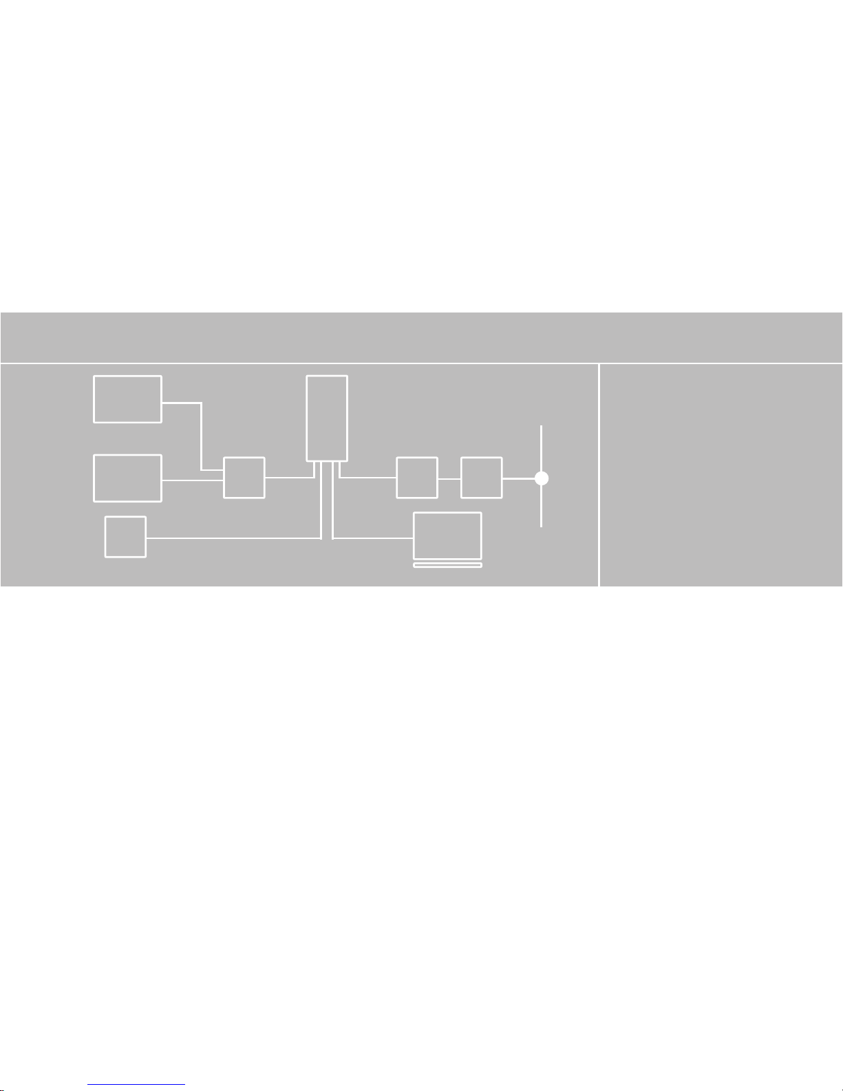
Standard components of a PV system
Depending on the recommendations
of your electrician, your PV system will
consist of the following components:
PC
(3)
INVERTER
PV
PV
(1)
(2)
(4)
GRID
PV generator switch:
Designed as DC load break cut-out to cut
off the PV generator from the solar inverter.
Dimensioning: min. 900 V, ≥ 16 A
Grid connection:
3-phase (Feed-in: 1-phase; grid monitoring:
3-phase)
Standard components of the PV system
97
(1) PV generator switch
(2) Irradiation sensor with
integrated temperature
sensor
(3) Mains fuse
(4) Energy meter
Page 12

Protection concept
The following parameters are monitored
continuously and in parallel by the microcontroller and displayed on the screen:
· DC overvoltage (Fault 3)
· Frequency error (Fault 4)
· Overheating (Fault 5)
· Grid undervoltage, 1-phase (Fault 6)
· Grid overvoltage, 1-phase (Fault 7)
· Grid undervoltage, 3-phase (Fault 8)
· AFI error (Fault 9)
· Insulation error (Fault 10)
· DC feed (Fault 11)
· Isolated operation (Fault 12)
· Grid overvoltage, 3-phase (Fault 13)
· Surge error (Fault 14)
· Grid voltage 10-minute average value
> 10 % U
NOM
(Fault 15)
98
In the event of a fault, the conversion is
blocked immediately and the grid relay is
isolated. An alarm relay with floating
output is activated (not for Fault 6).
In addition, the following protective
devices are provided on both grid and
PV generator side:
· Grid-side varistors
Protect the power semiconductors from
high-energy, time-limited voltage spikes
on the grid and provide for a reduction
of energy in the throttle in the event of
grid disconnection.
· Generator-side varistors
Thermally monitored varistors provide
protection against atmospheric overvoltages (e.g. due to remote strikes during
storms).
Page 13

200
2.0 Information on installation
99
Page 14
2.1 Safety information
!
100
Electrical safety
Before opening the cabinet, the solar
inverter must be disconnected from the
grid and from the PV generator.
The solar inverter conducts a hazardous
voltage internally and at the connectors of
the PV generator for approx. five minutes
after isolation from the PV generator and
the grid. The energy storage capacitors are
only fully discharged after this period.
After disconnecting the solar inverter from
the grid and PV generator, you must wait
at least five minutes before opening the
solar inverter.
Mechanical safety
During installation, make sure that the
cables or connection lines fitted to the
solar inverter are securely laid and that
suitable mechanical cable supports
(cable ducts etc.) are used.
Page 15

EN
!
101
Information on cleaning
Before cleaning, disconnect the system
from the power grid by opening the grid
breaker (main fuse) and open the DC
switch on the PV generator, in order to
exclude the danger of electric shocks.
Use a soft, dry cloth to clean the system.
Never use corrosive, solvent-containing
or abrasive cleaners or polishes.
Page 16
2.2 Basic configuration
Fixed voltage setting
Your Sunways solar inverter has a precise
MPP control. The control operates in fixed
voltage mode beneath a feed-in capacity
of 200 watts. This prevents unnecessary
MPP search behaviour. In order to minimise the adaptive losses in fixed voltage
mode, the solar inverter has the facility to
set the fixed voltage level. The optimal
fixed voltage level is dependent on your
PV generator model.
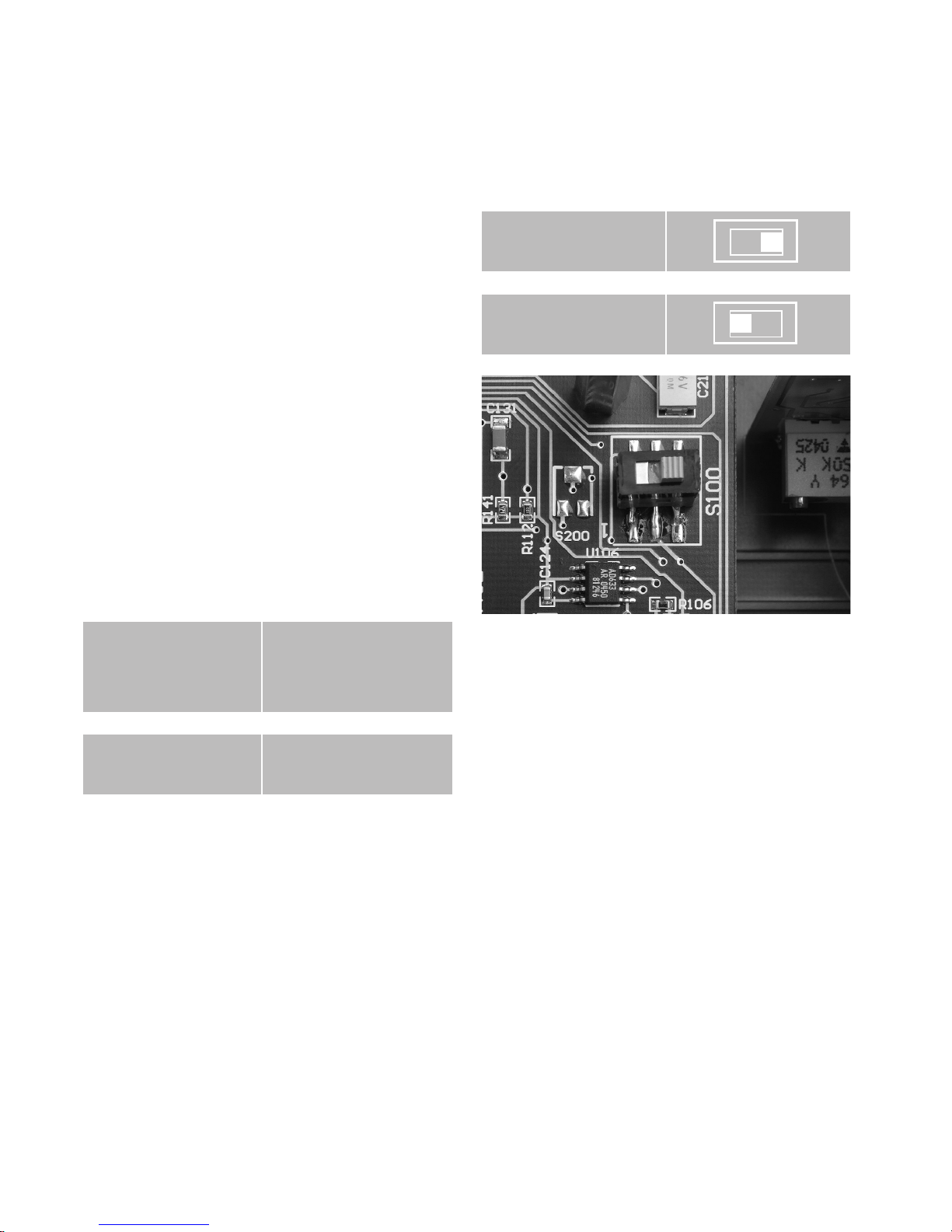
The fixed voltage can be set with the S100
slide switch on the control board. At the
factory, the switch is set on the right in
status «410 V». In order to set a fixed voltage of 530 V, slide the switch to the left
into the «530 V» position.
Fixed voltage level
depending on noload voltage
410 V
530 V
No-load voltage PV
generator at 25°C
≤ 630 V
> 630 V
Switch position
«410 V»
Switch position
«530 V»
(Fig.) Sliding switch to set the fixed
voltage level
102
Page 17
EN
Country selection
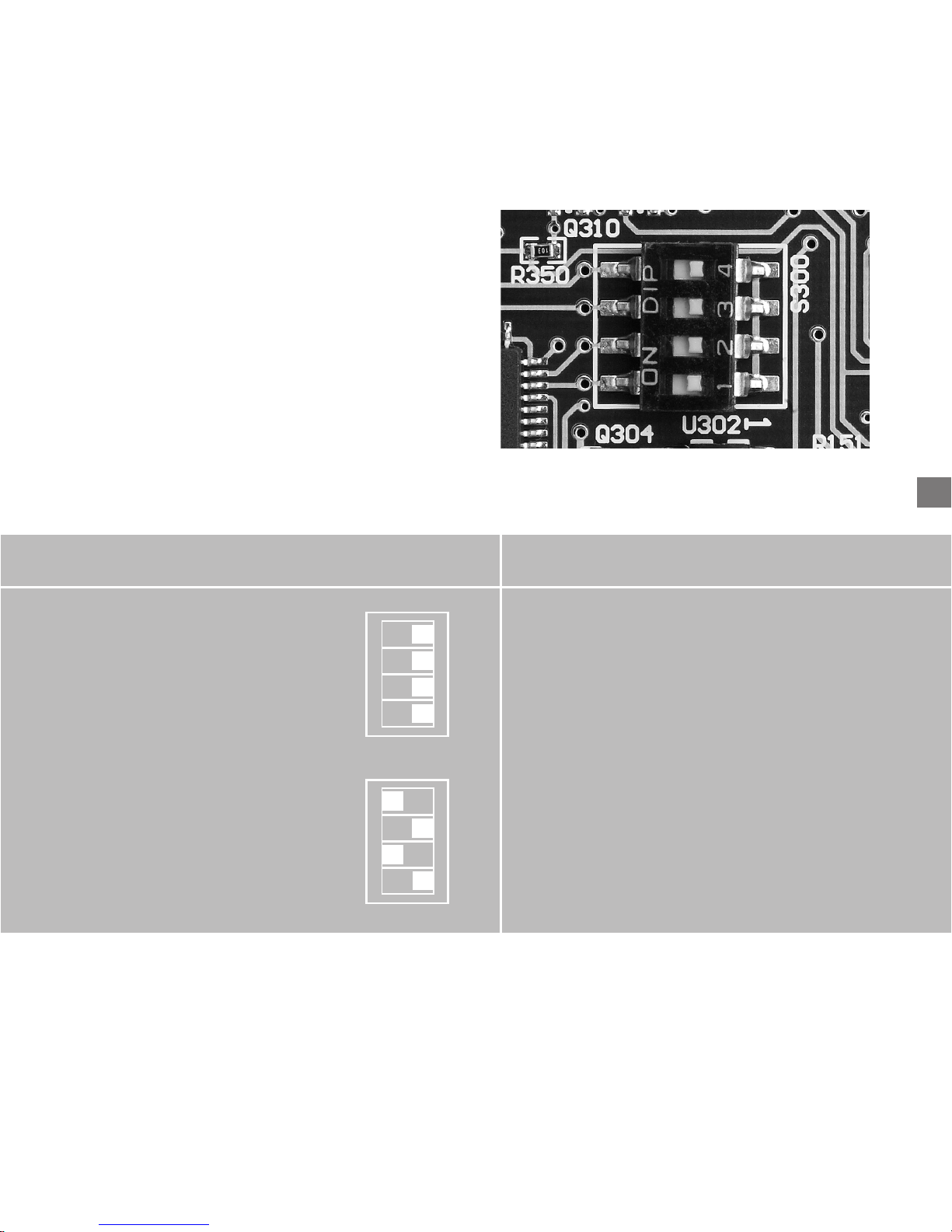
Please note that a different device configuration is required to operate Sunways
Solar Inverters in different countries. You
can make the relevant setting with DIP
switch S300 beneath the display panel.
Country
Germany
Spain
modification
· Disconnect interval after power failure
3 minutes
· 1-phase grid monitoring
switch position
(Fig.) DIP switch S300 for country selection
103
Page 18
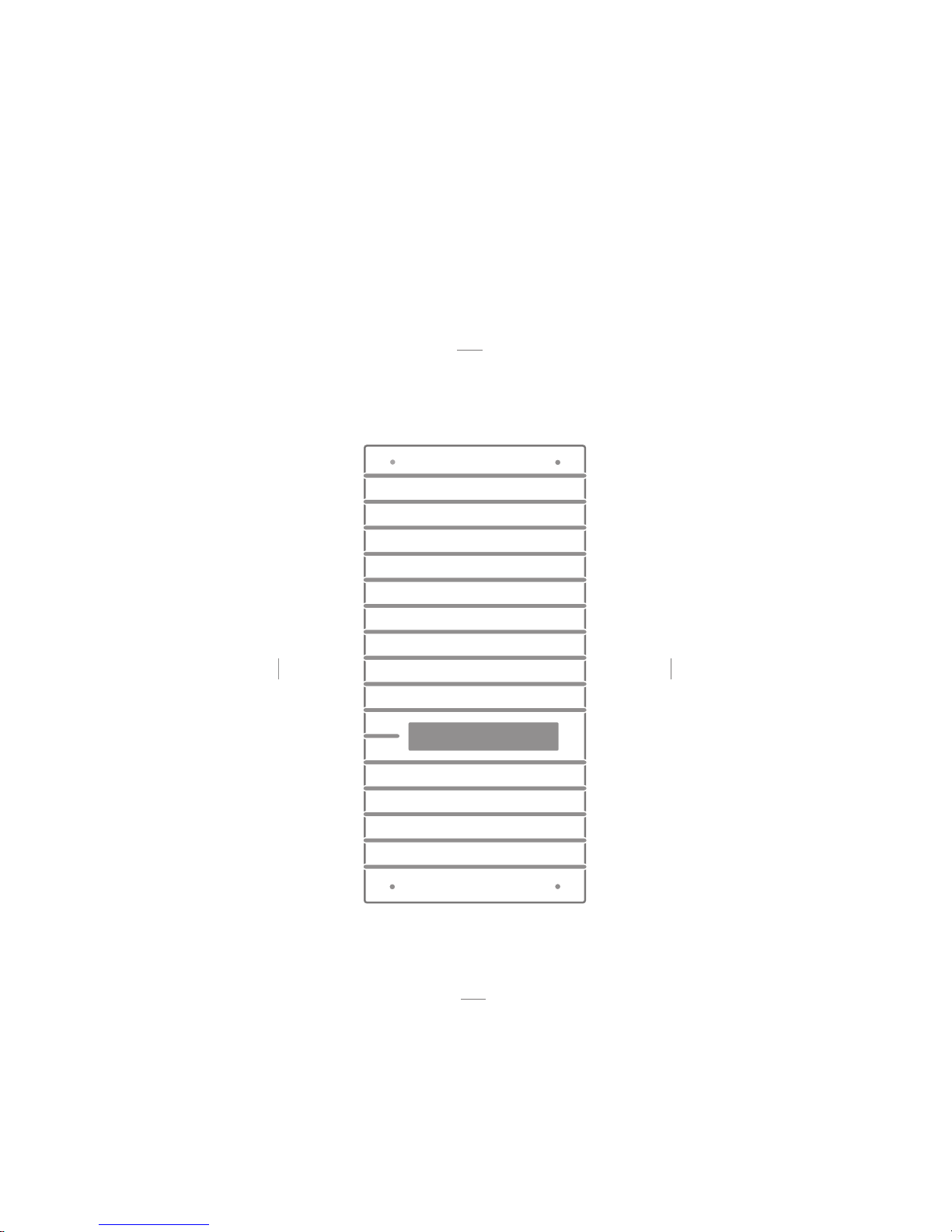
2.3 Installation
The solar inverter must be installed by a trained, qualified electrician. A special tool is
necessary for installation. Please read this chapter very carefully.
➟
150 mm
Cool air
Warm
air
300 mm
300 mm
150 mm
➟
➟
➟
(Fig.) Minimum
distances that
must be kept clear
around the solar
inverter
104
Page 19

EN
105
If installing the solar inverter in a switch
box, ensure adequate heat dissipation.
The ambient temperature must not fall
below or exceed –25°C or +40°C.
The solar inverter should not be exposed to
direct solar irradiation, so as to protect it
from unnecessary external heating.
· Protection from damp and foreign bodies
The IP54 high protection class permits installation both inside and in roofed outdoor
areas, but the solar inverter must not be
exposed to direct rain.
Make sure that the solar inverter cannot be
exposed to foreign bodies (deposits of dust
and dirt). In order to avoid losses in yield,
the unit should be regularly freed from dust
deposits.
Requirements on the place of installation
· Mechanical bearing capacity
During installation please bear in mind
that the solar inverter weighs 26 kg. The
installation base must be firm and capable
of continuously bearing the weight.
· Thermal interaction
The installation base must consist of
flame-retardant material (e.g. no wood or
plastic in the base; concrete and brickwork
are suitable), as the heat sink emits temperatures up to max. 85°C.
A minimum distance of 300 mm must be
maintained above and below the cabinet,
and 150 mm on right and left from other
units, cabinets, ceilings, cable ducts etc..
The solar inverter must be installed vertically, so as not to hinder adequate free
convection.
Several solar inverters must not be installed on top of each other, so as to prevent
reciprocal heating.
Page 20
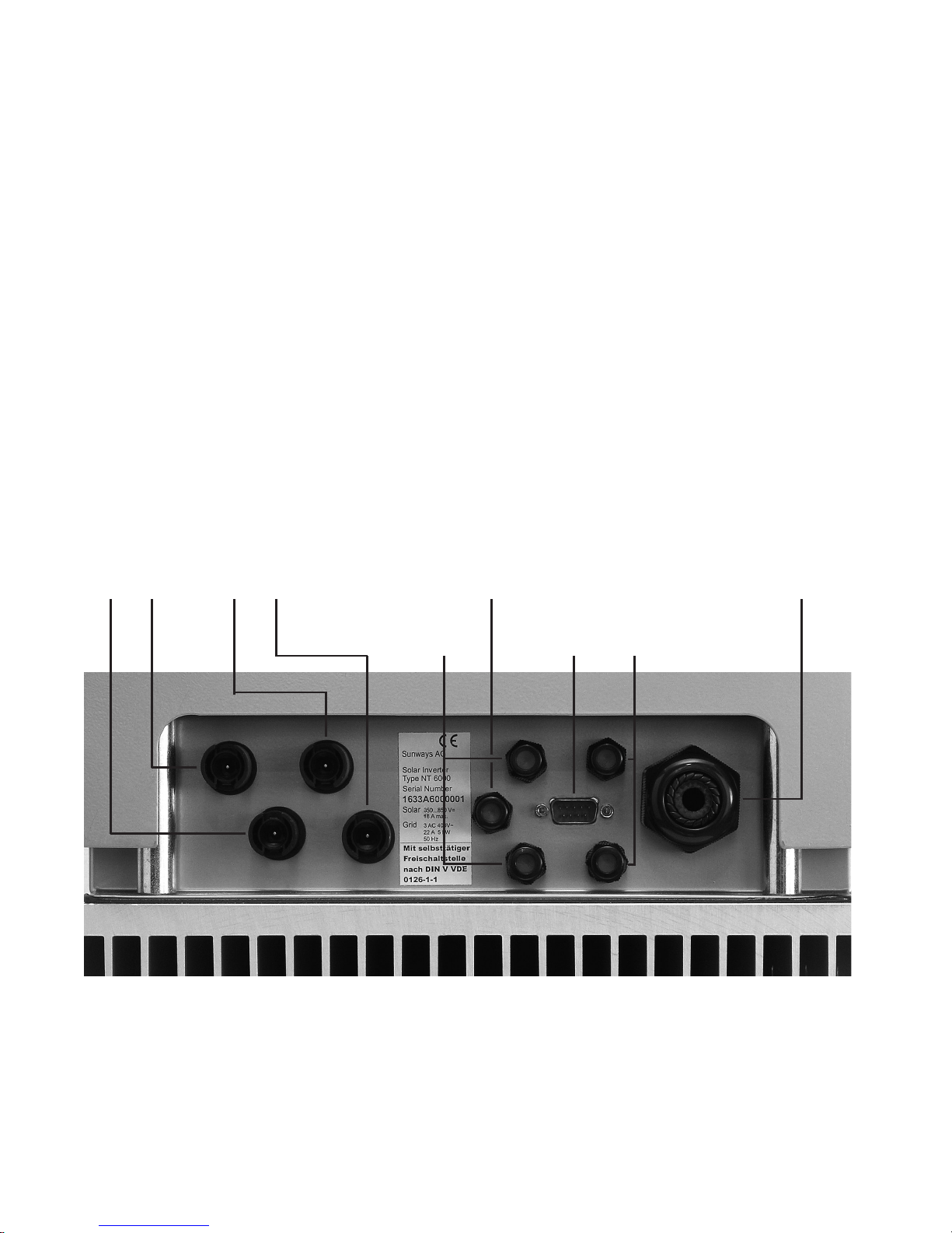
Electrical connection and cable entry
For installation, please observe the
instructions in the «Setup» leaflet!
!
If the solar inverter is fixed to the installation frame, the electrical connection can
be led through. The unit may only be opened by a qualified electrician. The cabinet
cover must first be released and removed.
The SUB-D connector for the RS 232 connection is located on the bottom, as well
as inlets for cables:
DC– DC– DC+ DC+
AC wiring loom
L1, N, L2, L3, PE
(Fig.) Inlets on the unit underside
Alarm relay
Irradiation sensor with
integrated temperature
sensor cable
RS 232
RS 485
106
Page 21
EN
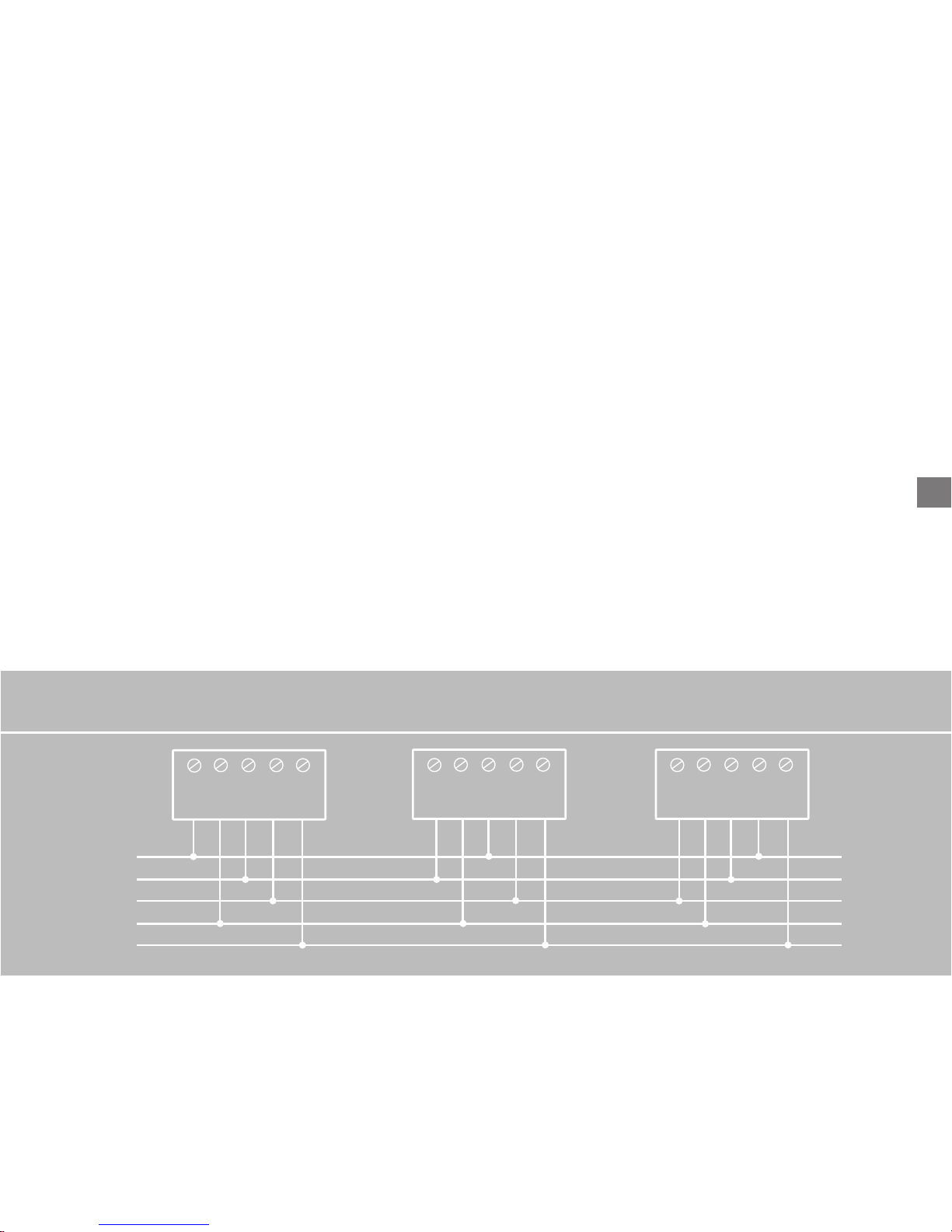
Grid connection
The grid connection of the solar inverter
must have 5 wires (L1, N, L2, L3, PE). Cable
cross-sections of 5 x 4 mm
2
are recommen-
ded.
The solar inverter is connected to the supply grid via the circuit board terminals inside the unit.
!
We recommend a 3 x 25 A safety cutout
for devices NT 6000, NT 5000 and NT 4000
and a 3 x 16 A safety cutout for device
NT 2600 as grid protection element in the
grid feed-in direction. No consumption
units must be connected to the feed line
from the solar inverter to the automatic
cut-out. The solar inverter only feeds in
via terminal L1. Please always observe the
connection configuration. Incorrect configuration can result in destruction of the
unit.
L1 N L2 L3 PE
L1 N L2 L3 PE L1 N L2 L3 PE
L1
L2
L3
N
PE
Three-phase grid connection distributed over three units
107
Page 22
If several solar inverters are operated in
parallel, the feed-in phase L1 of the unit
must be evenly distributed over grid phases L1, L2 and L3 (see Fig. page 107).
You must use adequately dimensioned
cable cross-sections in order to avoid a
considerable increase in the grid impedance between the domestic distribution
and the solar inverter. The terminal range
of the AC terminals is 0.5 to 6 mm2 for
rigid cables and 0.5 to 10 mm2 for flexible
cables. With a high grid impedance,
i.e. with a long line or too small a crosssection, the voltage increases at the grid
terminal during feed-in.
If the terminal voltage exceeds the permissible value, the solar inverter is discon-nected from the grid. In the case of
poorly designed electric grids and high
PV output, this can also result in repeated
switching off and on of individual solar
inverters.
Carefully perform the following steps:
· Check that there is no voltage before
introducing the supply main into the
unit.
· Lead the 5-core AC cable (outer diameter 9 – 17 mm) through the M32
threaded cable gland.
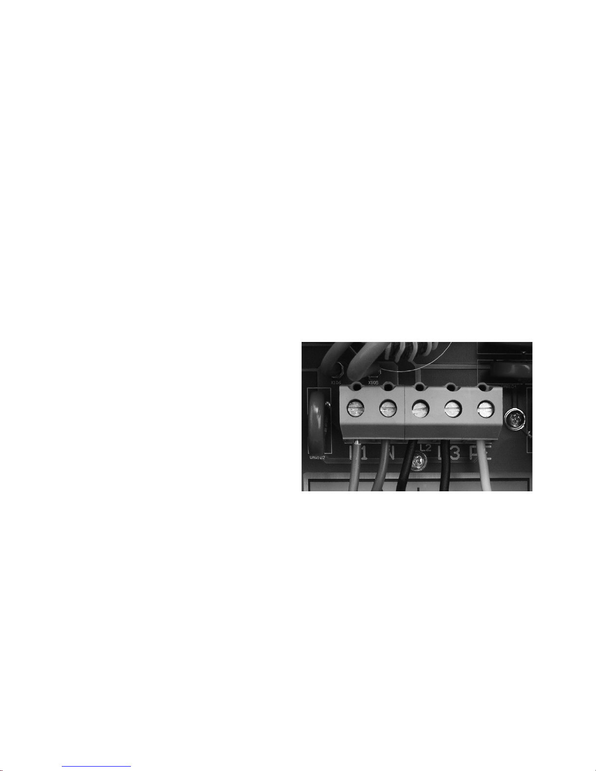
· Connect cables L1, N, L2, L3 and PE to
the relevant circuit board terminal with
the help of a slot-head screwdriver
(Fig.) Circuit board terminal for fixing
the grid cable
· Tighten the M32 screw connection, so
that the cable cannot exert any mechanical force on the circuit board terminal.
108
Page 23

EN
PV generator connection
!
· Preparation
Execute the DC cabling according to your
electrician's system dimensioning. Check
each PV string for correct functioning
by performing a no-load voltage current
and short-circuit current measurement.
Check the rating plate on the solar inverter to ensure that the inverter is approved for the maximum PV generator voltage.
To achieve the necessary protection
against hazardous contact voltage during
the installation of PV systems, the positive and negative conductors must be kept
separate from the ground potential (PE).
Contactable, conductive parts of the PV
generator (e.g. metal frame, supporting
structure etc.) must be earthed (connected to PE).
Check that the generator is free from
ground faults.
Make the electrical connection to the
solar inverter.
109
Page 24
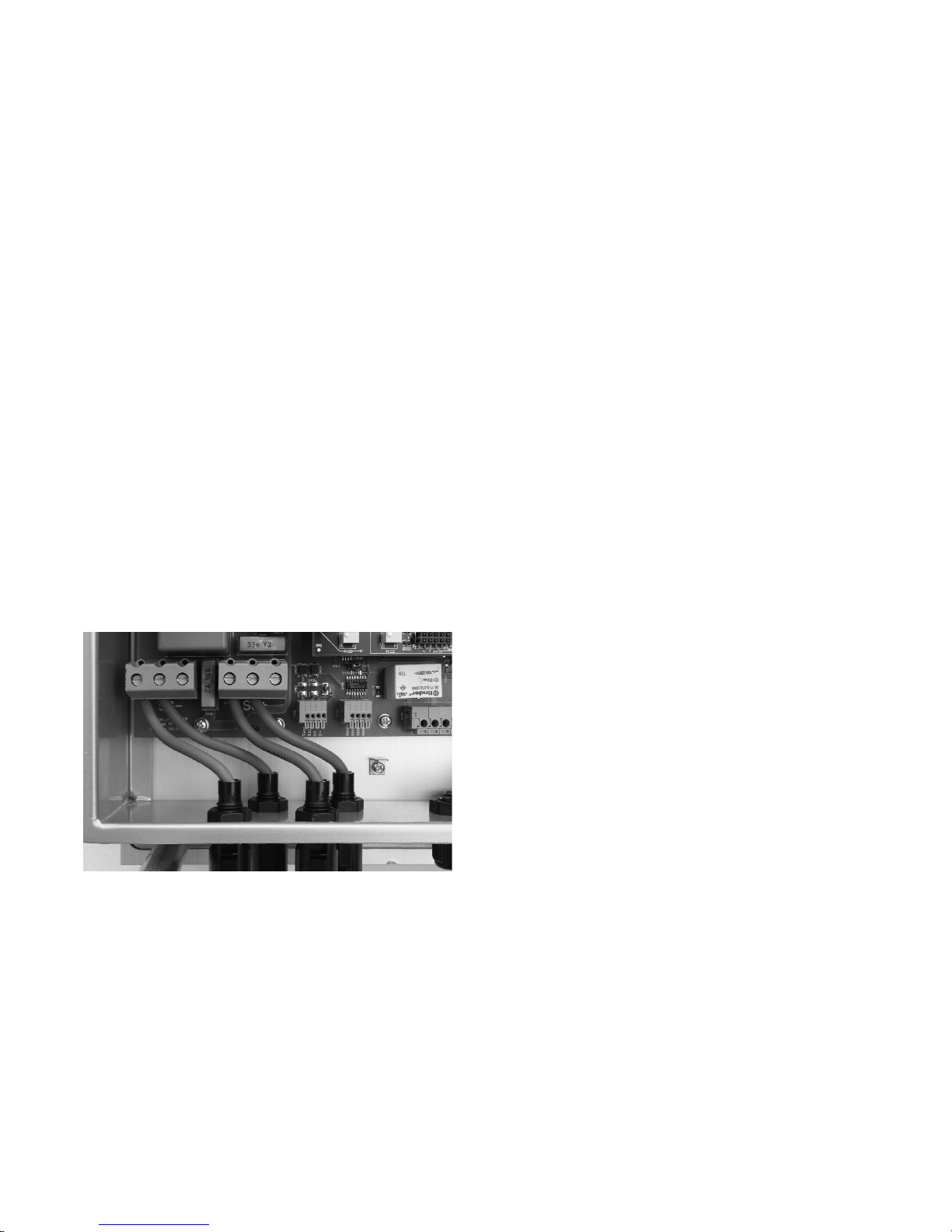
· Connection
The PV generator is connected via the
externally accessible, shock-proof Tyco
Solarlok connectors, which are enclosed
with the delivery. The Tyco Solarlok connectors are designed for a cable crosssection of 4 mm
2
and must be crimped
(see chapter 4.2 «Tyco Solarlok connection»).
Connect the two right DC female connectors with «+», the two left DC female
connectors with «–» of the PV generator.
Always ensure the correct polarity!
(Fig.) PV generator connection via Tyco
Solarlok connector
110
Page 25

EN
!
111
Important information
· The direct PV generator voltage is available internally after connecting the PV
generator to the solar inverter via the
DC connectors and switching on the PV
generator switch!
· Please note that the input capacitors are
still charged even after switching off the
PV generator switch or removing the PV
generator plug connection!
· After disconnecting the AC and DC side,
the solar inverter still conducts voltage
for up to ca. five minutes!
· Therefore, wait for at least five minutes
until the internal voltage has dissipated.
Then you can work on the terminals!
Note chapter 2.1 «Safety information»!
· The DC voltage can be up to 850 V. The
unit may only be opened by a qualified
electrician!
· Always disconnect the PV generator side
first by opening the PV generator switch,
and then the grid connection by isolating
the relevant mains fuse!
· If you do not have a PV generator switch
in your PV system, you must disconnect
the grid connection first of all by isolating the relevant mains fuse. However,
an error will be entered in the error
memory of the solar inverter!
· Disconnection of the PV generator by
removing the Tyco Solarlok DC connectors must never be performed under
load. In the event of non-compliance,
the connectors could be damaged by a
strong electric arc. In this case, the rele
vant connectors must be replaced!
Page 26
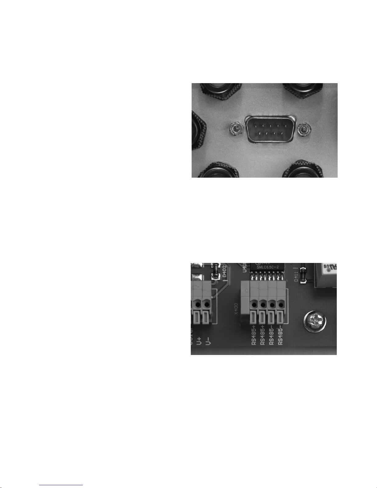
!
(Fig.) SUB-D connector for RS 232 connection
Attention: RS 485+ and RS 485- are duplicated. This means that the cable entry and
exit are additionally clamped.
(Fig.) Connection block for RS 485
112
Communication connections
Via the communication connections (interfaces), operating data can be retrieved
from the data memory with an external
computer and specific operating settings
made. Several communication interfaces
are available: RS 232 and RS 485.
The standard communication interface is
the RS 232 interface, which is installed in
all current PCs and notebooks. This interface allows you to establish contact with
your PC immediately, using a connecting
cable. The use of more than one solar
inverter or cable lengths of more than
25 m requires the use of the RS 485
interface.
The RS 232 interface is connected directly
to the outside of the housing via a SUB-D
connector. The RS 485 interface is connected via the circuit board terminals and the
corresponding M12 threaded cable glands
in the housing.
Page 27

EN
· Connection RS 485
Remove the cover of the solar inverter
before connecting an interface cable.
Note chapter 2.1 «Safety information»!
The necessary cable terminal block (X400)
with the RS 485+, RS 485+, RS 485- and RS
485- connections is located in the lower
section of the board (see fig. page 112).
Note the following terminal configuration:
RS 485: RS 485+, RS 485+, RS 485-, RS 485-
Use a small screwdriver. Press the orange
terminal. The terminal will open.
Insert the cable stripped to a minimum of
11 mm into the respective terminal hole.
Release the screwdriver. The cable is fixed
in the connection.
Once again, check that the cable connection is firmly located.
Seal the unrequired cable glands by placing a spare piece of cable in the gland
hole and tightening with the screw clamp.
Please note chapter 3.2 «Sunways NT
Monitor software».
· RS 232 connection
The RS 232 interface is externally accessible
via the SUB-D connector.
Please note chapter 3.2 «Sunways NT
Monitor software».
113
Page 28
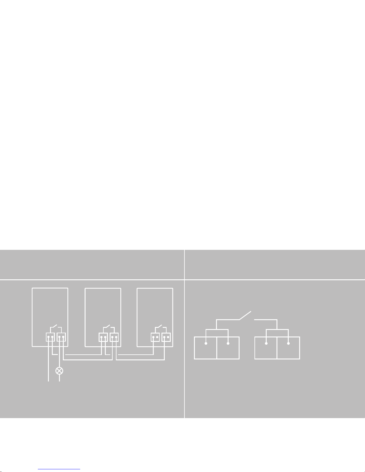
Connection of the alarm relay
Sunways Solar Inverters are equipped as
standard with an alarm relay with floating
output. The relay is designed as a make
contact and is activated in the case of all
faults reported by the unit (not for Fault 6).
This guarantees quick and reliable indication of possible faults in the PV system.
In the case of PV systems with several
solar inverters,the individual relays can
!
be parallel-connected and connected via
a joint signal light.
· Connection
Remove the housing of the solar inverter
before connecting the status signal relay.
Note chapter 2.1 «Safety information»!
The necessary terminal block with the connections «S-» and «S+» is located on the
board at the bottom right (X402). Note the
following terminal configuration:
L1 N
Parallel connection of the alarm relays of
several solar inverters
INVERTER
(1)
SIGNAL LIGHT
INVERTER
(n)
INVERTER
(2)
S– S– S+ S+
Terminal configuration for the alarm relay
Page 29
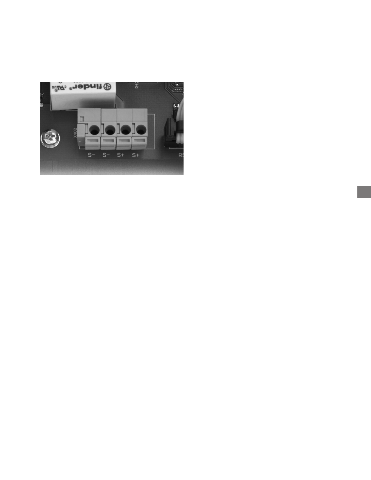
(Fig.) Connection of the alarm relay
Important information: The alarm relay is
designed for 230 V / 2 A. Higher outputs /
voltages can result in destruction of the
relay. The connected signal input must
have separate fuse protection!
Using a small screwdriver, press the orange
terminal. The terminal will open. Insert the
minimum 11 mm stripped cable into the
respective terminal hole. Loosen the screwdriver. The cable is fixed in the connection.
Once again, check that the cable connection is firmly located.
EN
The terminals are designed for a cable
cross-section of 0.2 mm
2
to 1.5 mm2.
Please also take account of the power
consumption of the connected signal
input when dimensioning the cross-section!
!
115
Page 30
!
116
Connecting the sensors
· Optional irradiation sensor
The optional addition of an irradiation
sensor (type Si-01TC-T from Ing.-Büro
Mencke & Tegtmeyer ) with integrated
PT-100 temperature sensor for temperature measurement enables recording of
the irradiation data and the corresponding module temperature in the cycle
of the internal data memory.
This additional measuring unit helps with
analysis of the system. On the basis of the
values, possible errors in the PV generator,
such as e.g. shading or failure of solar cells,
can be detected.
For demonstration purposes, the irradiation sensor and the corresponding data
can be used to show how a PV system
functions. In conjunction with the
Sunways NT Monitor visualisation software, the stored data can be displayed.
Before you connect an irradiation sensor,
you must remove the cover of the solar
inverter. Please note that the inputs and
outputs are not short-circuit resistant.
Note chapter 2.1 «Safety information»!
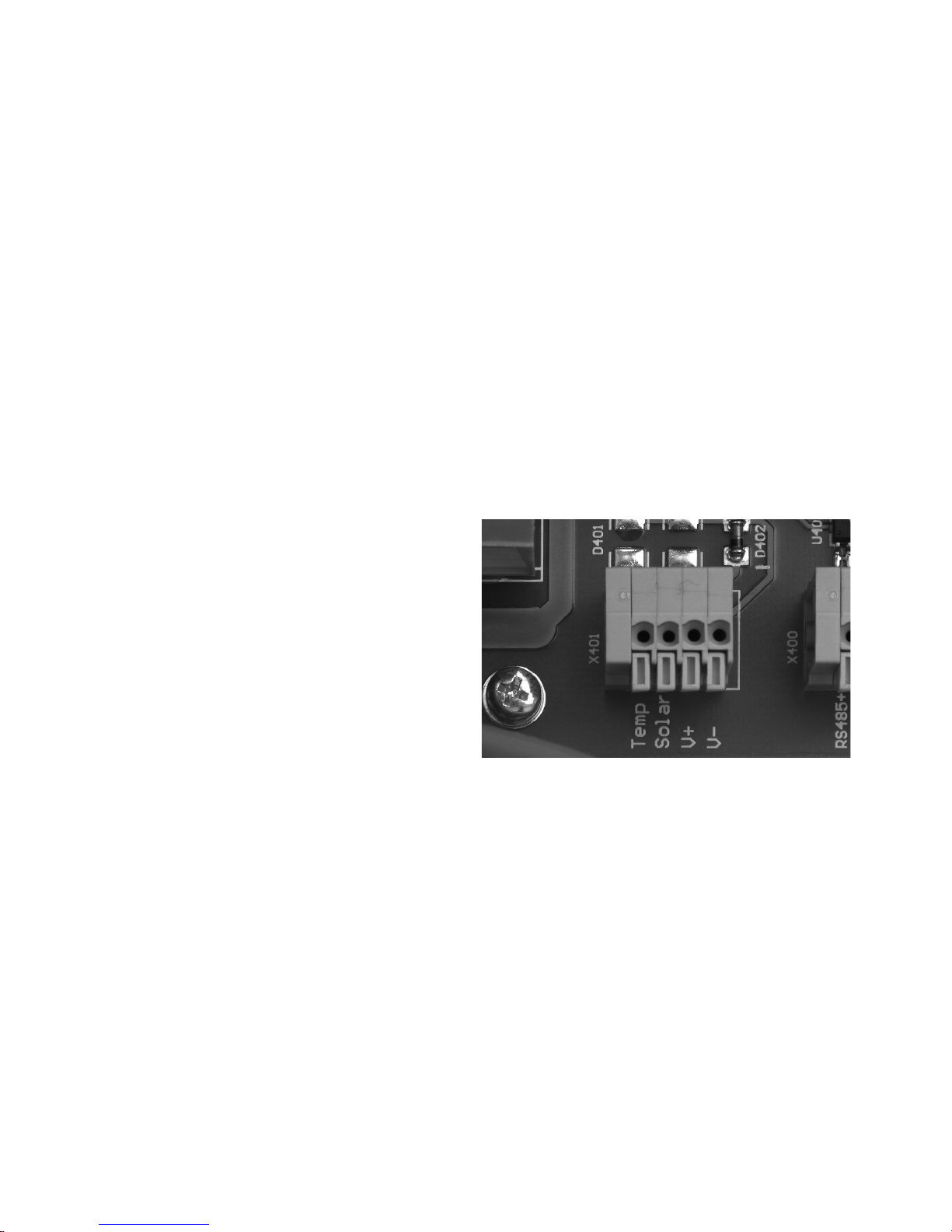
The optional irradiation sensor with temperature probe is connected to cable
terminal block X401 in the lower section
of the board.
(Fig.) Connection block for the irradiation
sensor
Page 31

EN
117
Configuration of the cable terminal block:
Temperature sensor
measuring signal: Temp
Solar radiation
measuring signal: Solar
Positive supply, 5V: V+
Supply, GND: V –
Using a small screwdriver, press the orange
terminal. The terminal will open.
Insert the cable stripped to a minimum of
11 mm into the respective terminal hole.
Loosen the screwdriver. The cable is fixed
in the connection.
Once again, check that the cable connection is firmly located.
Page 32

118
2.4 Commissioning
Connect the solar inverter internally via
the ground cable (yellow-green) to the
cabinet cover. See also Setup, step 7.
Put the cabinet cover on.
Screw it down tightly with the four
screws on the front.
Do not place any objects (e.g. this manual) on the cabinet of the solarinverter.
Free ventilation behind the solar inverter
must be able to take place unimpeded.
If the unit is mounted outdoors, please
ensure proper sealing of the threaded
cable glands and precise positioning of
the housing cover as well as the protective cover of the SUB-D connector, if this
connection is not configured.
Switching the solar inverter on and off
· Switching on
When the solar inverter is mechanically
installed and connected to the electrical
cables, the unit can be commissioned as
follows:
Switch the grid connection on through
the external safety cutouts.
Switch the PV generator voltage on by
closing the PV generator switch. The solar
inverter will start up with adequate
PV power. If the PV input voltage is high
enough, the solar inverter will begin operation and feed the solar energy into the
electrical grid. You can see the operation
on the display. The current feed-in power
is shown here.
The solar inverter is supplied by the grid.
With adequate PV output, the solar inverter switches on automatically. Appropriate
switch-on and switch-off thresholds are
fixed for this purpose.
Page 33

EN
!
119
· Switching off
Disconnect the PV generator side first by
opening the PV generator switch, and
then the grid connection by isolating the
relevant mains fuse.
If your PV system does not have a PV
generator switch, you must disconnect
the grid connection first of all by isolating
the relevant mains fuse. When you do
this, an error will be entered in the error
memory of the solar inverter.
If the solar inverter is to be completely
disconnected (e.g. removal) from the PV
system, reconfigured or extended, the
cabinet cover must be removed. Note
chapter 2.1 «Safety information»!
Open the main switch for the PV DC
voltage and the mains fuse as described
above. After a waiting period of at least
five minutes, the solar inverter will be
voltage-free.
Disconnection of the PV generator by
removing the Tyco Solarlok connectors
must never be performed under load.
In the event of non-compliance, the connectors could be damaged by a strong
electric arc. In this case, the relevant connectors must be replaced!
Remove the cabinet cover.
Check that the grid connection terminals
are voltage-free.
Page 34
!
120
However, language setting, LCD contrast
and total energy offset (only to be used
in the event of replacement) must be
configured directly on the unit. If you wish
to configure the solar inverter without
an external laptop or PC, or to change the
language setting, please follow the
instructions below:
Direct configuration of the solar inverter
occurs in operation!
Please note that the unit is under DC
voltage for configurations via the keys.
Danger to life!
Please observe all essential regulations for
«Working under voltage»!
Configurations
The solar inverter is basically configured
with the Sunways NT Monitor program,
using a laptop or PC (see enclosed CD).
Please read the chapter 3.1 «System
Monitoring and Diagnosis» and 3.2
«Sunways NT Monitor».
Page 35
EN
AD
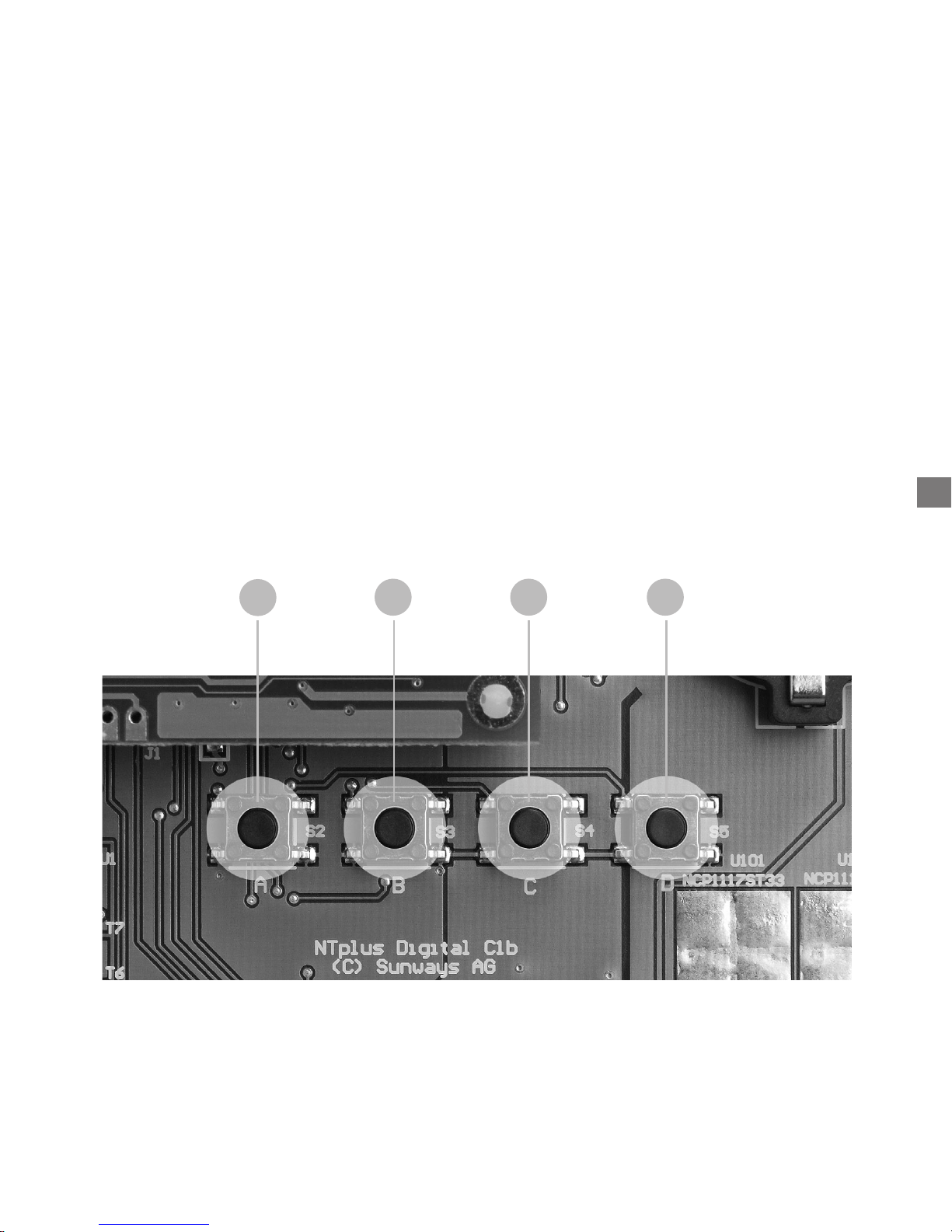
(Fig.) The setting keys are located beneath the display
B
C
121
This is the only exception for which work
may be performed on the open unit under
voltage!
Remove the cabinet cover to carry out the
configuration.
The following settings can be performed
using the illustrated keys:
· Address of the solar inverter: address
«1» is stored in the memory at the
factory. In the case of several solar inverters, consecutive numbering must be set.
For three solar inverters e.g. the addresses «1», «2» and «3».
· Date
· Time
· Language (German, English, French,
Spanish, Italian)
Page 36
SOLAR INVERTER
ADRESS
PERFORMANCE
AND
OPERATING DATA
DATE TIME
HOURS
A
B
MINUTES
A
B
SECONDS
A
B
SAVE
ADRESS
1 ... 99
A
B
DAY
A
B
MONTH
A
B
YEAR
A
B
D
START
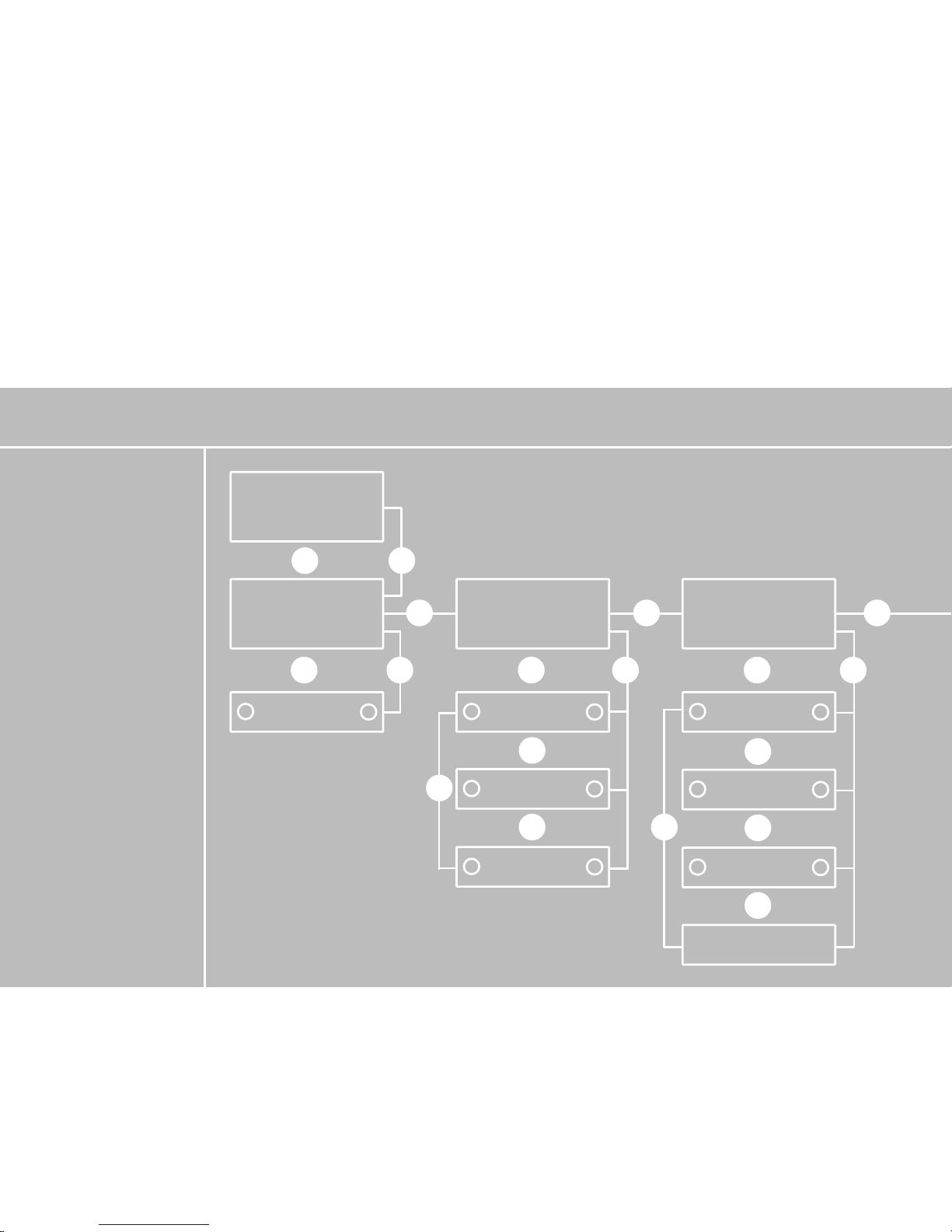
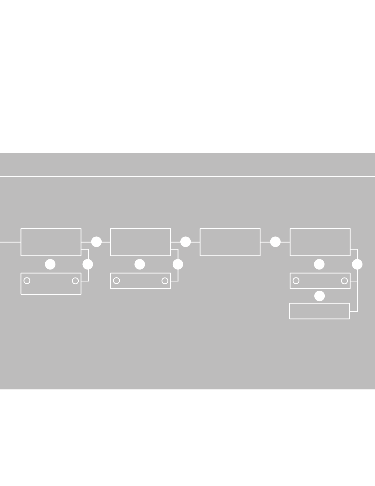
Structure and menu levels for configuration
▲
Use insulating material to press the keys
(e.g. a plastic rod). Avoid direct contact
with the printed circuit board, so that the
electronics cannot be damaged by electrostatic charging. Starting from the current
display on the screen, you can reach the
next menu level with the D-key. The illustrated structure facilitates settings on the
menu levels. Then save your settings by
pressing the C-key.
D D D D D D
C
C
C C
C
C
C
C
A/B A/B A/B
122
Page 37
LANGUAGE
SOFTWARE
VERSION
ENGLISH/GERMAN/
ITALIAN/FRENCH/
SPANISH
A
B
LCD CONTRAST
CONTRAST
A
B
TOTAL POWER
OFFSET
kWh
A
B
INCREMENT
(100 OR 1)
D D D D D D
C
A/B A/B A/B
123
Page 38

3.0 Information on operation
124
Page 39
3.1 Monitoring and diagnosis
Display
The dot matrix LCD display is integrated
into the cabinet of the solar inverter so
that it is easily visible. The display consists
of 16 characters and 2 lines. The top line 1
shows the current feed-in power of the
solar inverter. The bottom line 2 outputs
operating data. The data can be displayed
in the German, English, French, Spanish or
Italian language.
* if the optional irradiation sensor with
integrated temperature sensor is connected
EN
Line 1 Current fed-in power Power kW
Line 2 AC voltage U-AC V
DC voltage U-DC V
Daily yield W-DAY Wh
Total yield W-TOT kWh
Irradiation * SOLAR W/m
2
PV generator temperature * TEMP-PAN °C
Time TIME
125
Page 40

126
Data memory
Your solar inverter is equipped with an
internal data memory as standard. This
data memory provides you with a detailed
view of the mode of functioning and the
relevant values of your solar power supply
at all times. You can access these data
with the help of the NT Monitor software
described below. The following measured
values can be determined:
· DC voltage
· AC voltage and AC current (power calculation)
· Irradiation and module temperature
(if a sensor is connected)
· Time and date
The following values are accumulated,
stored and continuously overwritten:
· 15 minute values for AC current, DC and
AC voltages, irradiation and temperature
· 500 times storage of 15-minute average
values in the recirculating storage; storage depth: ten days on average, then
overwriting of values
· Storage of accumulated daily work in
Wh and of 40 daily values in the recirculating storage and successive overwriting
of values
· Storage of accumulated monthly work in
kWh and of 13 monthly values in the
recirculating storage, then overwriting
of values
· Storage of faults with max. ten values,
then successive overwriting of values
Please note that all displayed data are
displayed with a nominal measuring accuracy of maximum 5 per cent. The energy
counter of your EVU should be used as
absolute reference for the fed-in energy.
Page 41

EN
127
3.2 Sunways NT Monitor software
General information
The Sunways NT Monitor visualisation software was developed for PV system monitoring and configuration of the solar inverter
using PC. It is contained on the enclosed CD
and can also be downloaded free of charge
on the Internet from www.sunways.de.
System prerequisites are:
· Intel Pentium from 100 MHz or higher
· Microsoft Windows 95/98/2000/NT
· At least 6 MB free hard disk storage space
· At least 16 MB main memory
· VGA monitor with at least 800 x 600
(120 dpi) resolution
All measured values can be transferred
to a PC and visualised with the Sunways NT
Monitor software. Online, fault, minute,
daily and monthly values are available.
For connecting to your PC, Sunways solar
inverters in the NT series are equipped with
the RS 232 and RS 485 interfaces as standard. In the case of larger distances between PV system and PC, the data can also
be transferred via a modem. We recommend using two external analogue
modems made by ACER. If other modems
are used, the functional reliability cannot
always be guaranteed.
The modem (remote modem) installed
in the solar inverter must be initialised
prior to installation with the help of the
Sunways NT Monitor software. Note the
"Help" function in the program in this
regard.
The second modem (local modem) is
connected to the RS 232 interface of your
PC. This modem must not be initialised.
Different interface cables are required,
depending on the type of connection.
These are included in the accessories.
Up to 99 solar inverters can be monitored
and read out by means of a connection
via the RS 485 interface.
If the data are read out via the RS 485
interface and converted to RS 232 with
an interface converter, we recommend
the converter type «I-7520 Converter»
Page 42

128
from ICP-Deutschland, (available from your
specialist dealer), which will guarantee
reliable data transfer.
The addresses of the solar inverter must
be input with the Sunways NT Monitor
software. Alternatively, see chapter 2.4
«Commissioning, configurations».
Initialising the remote modem
If a remote modem is installed in the solar
inverter, it must be initialised using a PC
and the Sunways NT Monitor software.
· Connect the powered remote modem to
the PC via the COM port. Use the interface cable provided with the modem for
this purpose. Start the Sunways NT
Monitor and set «Acer Modem» under
the «Settings/Remote Modem» menu.
· Click «Perform initialisation» and wait
until the scroll bar has come to an end.
The modem can now be switched off
and connected to the solar inverter via
the RS 232 interface.
· Attention! Do not initialise the local
modem which is intended for use on
the PC!
· The remote modem is now initialised
so that it automatically accepts a connection after two rings and connects at
9600 Baud.
Page 43
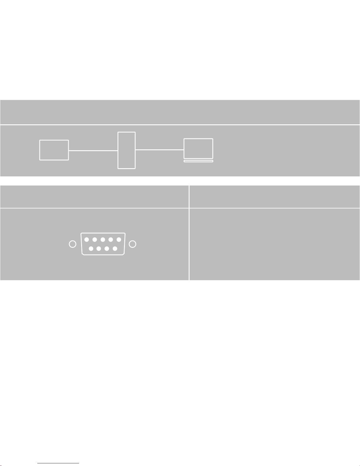
(1) Individual PV system with maximum distance of 25 m between solar inverter an PC
Connection to the PC via RS 232
An individual solar inverter can be connected
directly to the PC via the external RS 232
interface on the bottom of the device.
Jumper JP400: open
Connection and circuitry options
(1) An individual solar inverter can be
read out using this connection, unless the
distance from the PC exceeds a distance
of 25 m. For this purpose, cable type 1 is
connected with the solar inverter via the
SUB-D connector and connected to a PC.
Jumper JP400 must be in open position.
PC
INVERTER
(1)
PV
RS 232
SUB-D connector
129
Page 44
(2) Individual PV system with modem for remote inquiry
Connection to modem via RS 232
When connecting an individual solar inverter,
the remote modem is connected directly to an
external interface converter (IC) RS 232 at the
bottom of the solar inverter.
Jumper JP400: open
(2) For installation of the remote inquiry
of an individual solar inverter, the RS 232
signal can be conducted directly from the
solar inverter to the remote modem via
the SUB-D connector. Cable type 2 is used
for this purpose. A cable length of 25 m
should not be exceeded for the RS 232
connection between solar inverter and
modem. Jumper JP400 must be in open
position.
INVERTER
(1)
PV
PC
MODEM
MODEM
RS 232
RS 232
SUB-D connector
130
Page 45
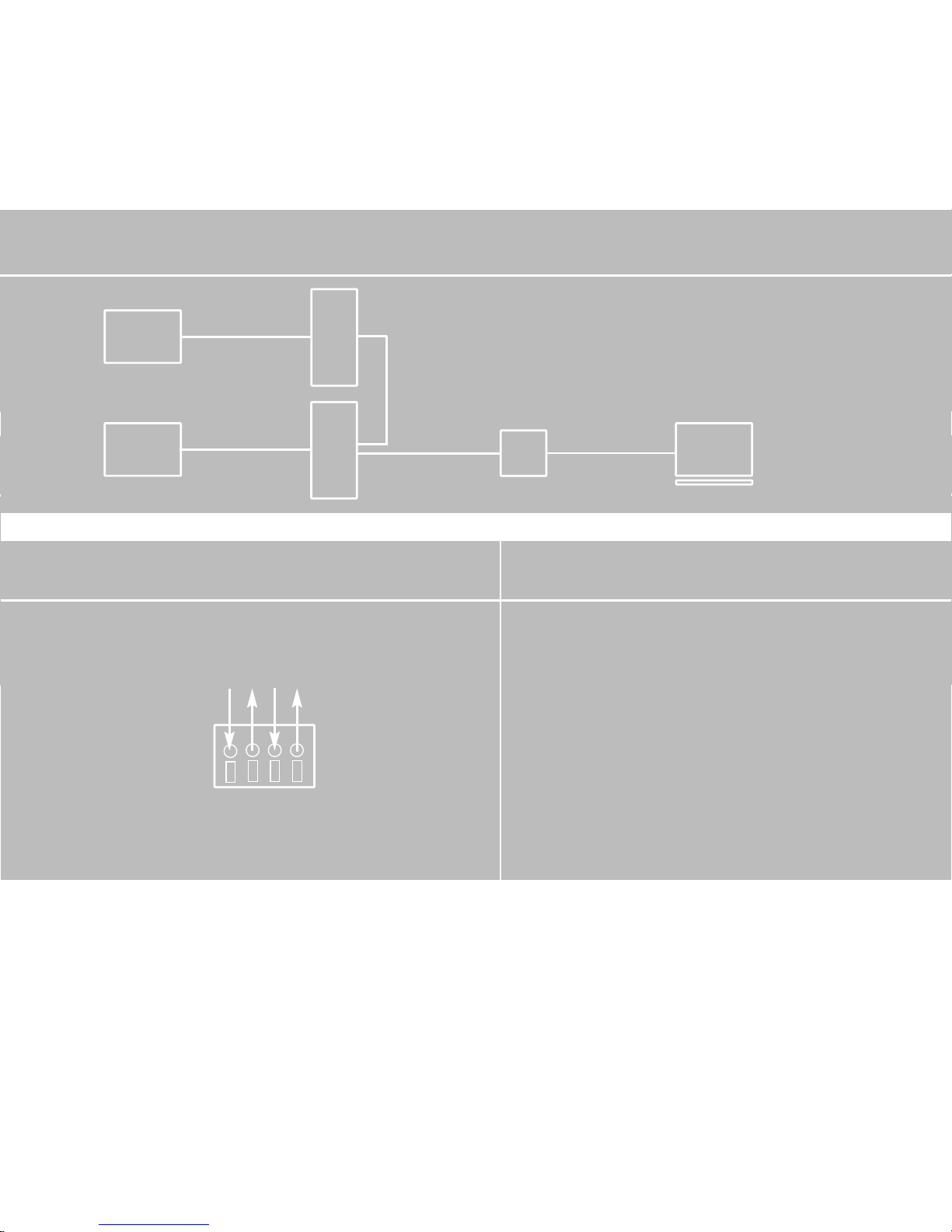
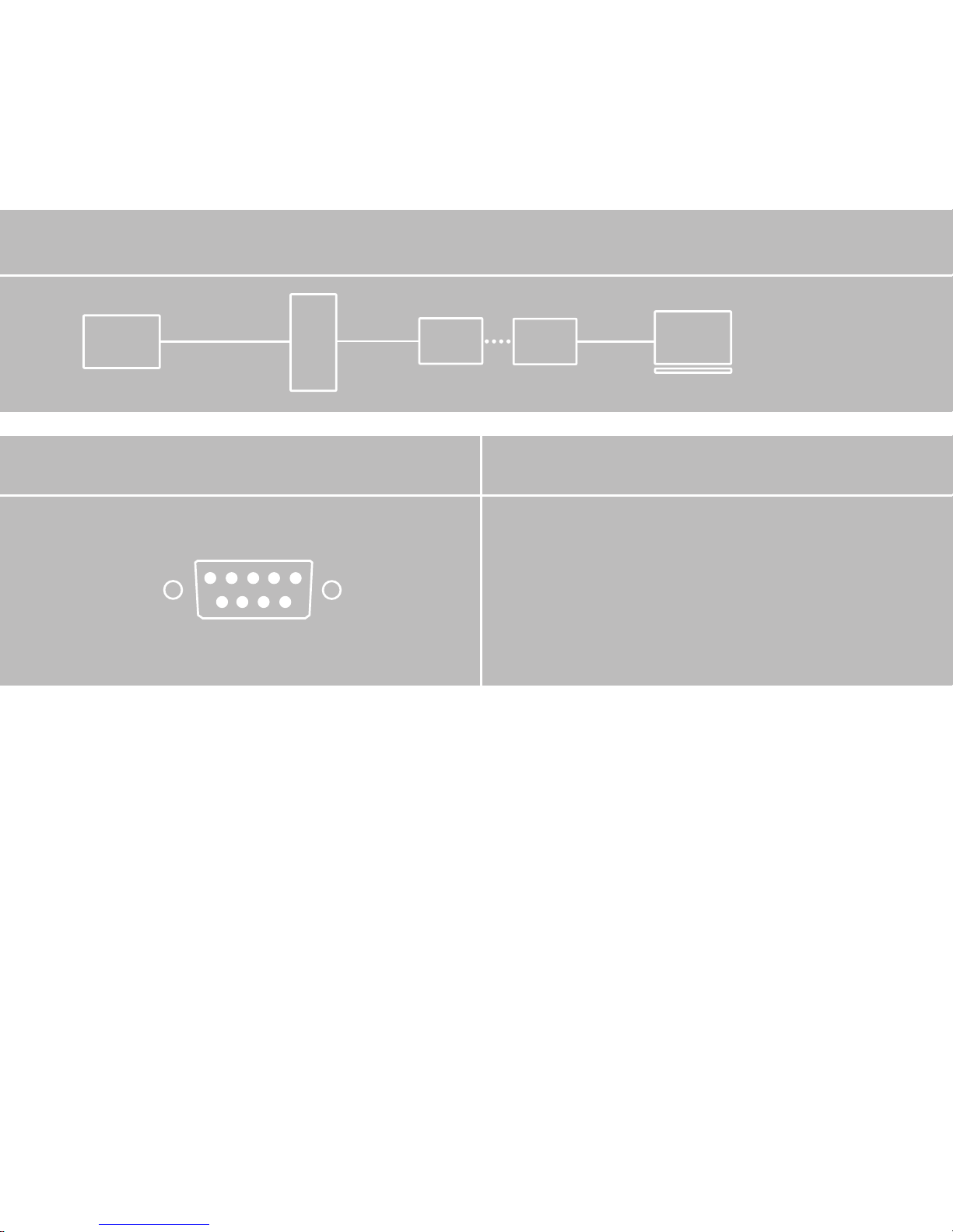
(3) PV system for 2 to 99 solar inverters with interface converter (IC) RS 485 / RS 232
Connection to PC via RS 485 / RS 232
In order to connect several solar inverters to a
PC, the RS 485 signal is looped through from
inverter to inverter, until it is led into the interface converter. From here, the RS 232 signal is
conducted to the PC. Jumper JP400 is connected
to the solar inverter that is furthest away from
the interface converter. It must be open for all
other solar inverters.
Stripped length: 11 mm
Jumper JP400: see above
(3) Up to 99 solar inverters can be connected together and read out using this connection. In this case, there is a maximum
cable length of 500 m between
the interface converter and the furthest
solar inverter. The individual solar inverters
are connected together via the RS 485
interface.
PC
SSW
INVERTER
(2 bis 99)
INVERTER
(1)
PV
PV
RS 232
RS 485
RS 485+
RS 485+
RS 485–
RS 485–
RS 485+
RS 485+
RS 485–
RS 485–
131
Page 46
PC
SSW
INVERTER
(2 bis 99)
INVERTER
(1)
PV
PV
MODEM
MODEM
RS 232
RS 232
RS 485
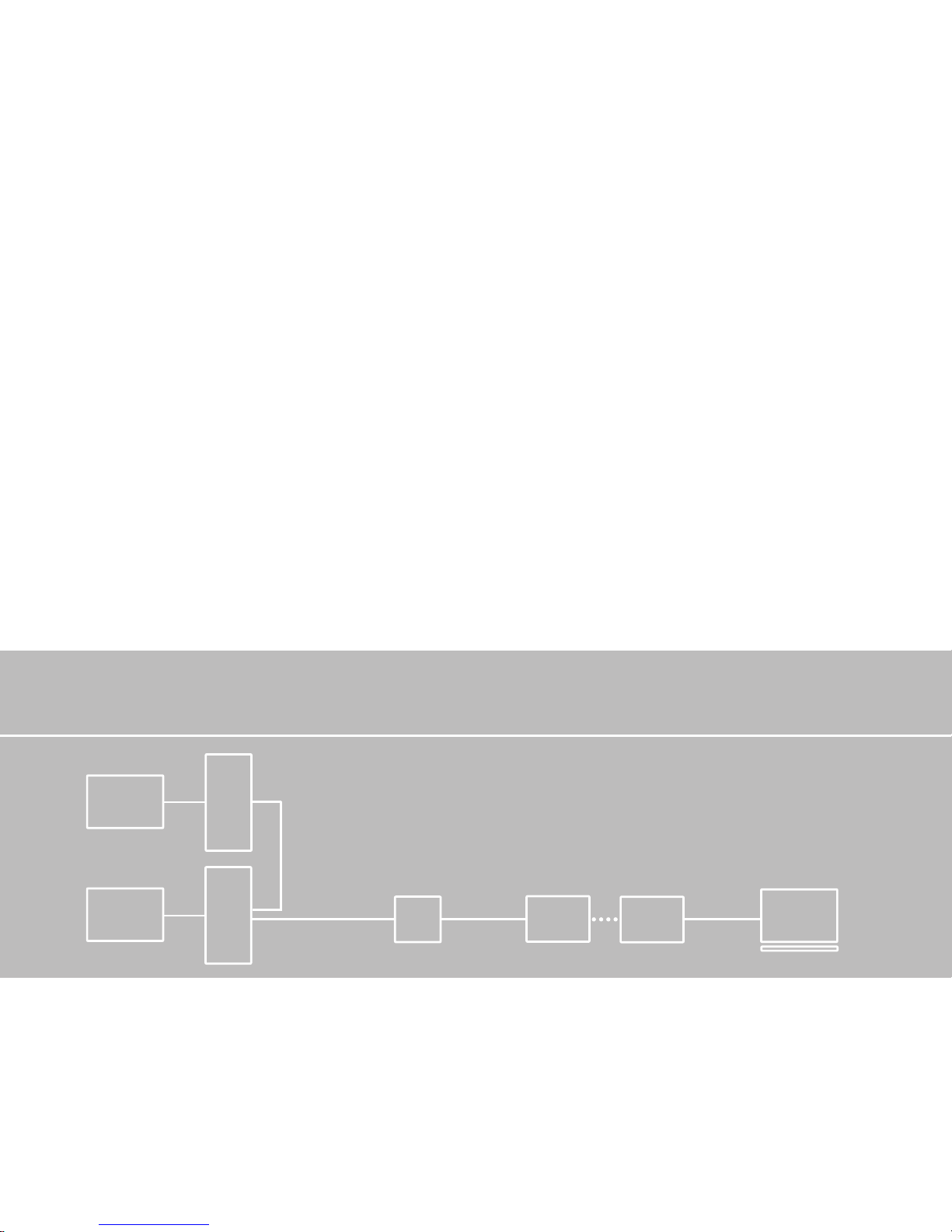
(4) PV system for 2 to 99 solar inverters with interface converter (IC) and modem for
remote inquiry
132
The signal is looped through all units. Two
«RS 485+» terminals and two «RS 485-»
terminals are located on each terminal
block. This means that the signal can be led
into the solar inverter at one terminal and
out of the solar inverter at the other terminal. The RS 485 signal is led out of the last
solar inverter in the series into the interface
converter using the following configuration:
«RS 485+» to «DATA+» and «RS 485-» to
«DATA-».
The interface converter generates an
RS 232 signal. It is connected to the PC with
the standard modem cable type D. Jumper
JP400 must be closed at the solar inverter
that is furthest away from the interface
converter. For all other solar inverters it
must be open. An address must be allocated, to enable identification of the individual solar inverters. Note chapter 2.4
«Commissioning, configurations».
Page 47
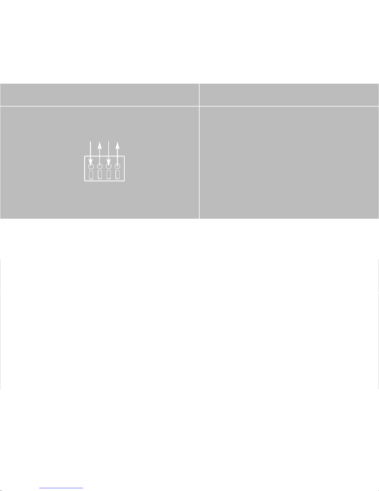
Connection to modem via RS 485 / RS 232
In order to connect several solar inverters to the
remote monitoring, the interface converter is
connected directly to a modem via RS 232.
Jumper JP400 is connected to the solar inverter
that is furthest away from the interface converter. It must be open for all other solar inverters.
Stripped length: 11 mm
Jumper JP400: see above
(4) If several solar inverters are to be connected to the remote inquiry, then the
individual inverters are connected together
by means of the RS 485 signal, as when
reading out several units locally. This signal
is converted by the interface converter
into the RS 232 signal, from where it is led
to the modem using cable type 3. Jumper
JP400 must be closed at the solar inverter
that is furthest away from the interface
converter. For all other solar inverters it
must be open. An address must be allocated, to enable identification of the individual solar inverters. Note chapter 2.4
«Commissioning, configurations».
RS 485+
RS 485+
RS 485–
RS 485–
RS 485+
RS 485+
RS 485–
RS 485–
133
Page 48
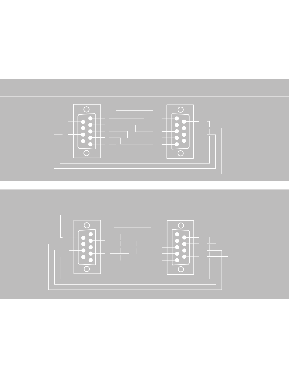
Configuring the interface cables
Cable type 1
Female
connector to
PC, 9-pole
1
2
3
4
5
6
7
8
9
5
4
3
2
1
9
8
7
6
Cable type 2 (Provided in the scope of supply of the «Acer» modem)
Connector
to modem,
9-pole
1
2
3
4
5
6
7
8
9
5
4
3
2
1
9
8
7
6
9-pole female
connector to
solar inverter
9-pole female
connector to
solar inverter
134
Page 49
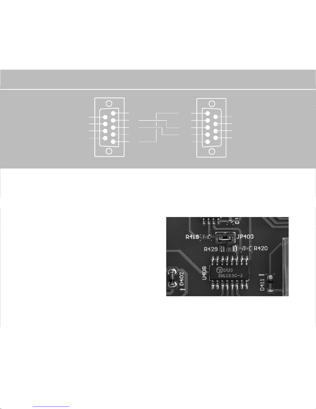
Jumper JP400 in the Sunways Solar
Inverter
Please check the correct position of jumper JP400, depending on your selected
communication circuit. This jumper is
located above the RS 485 communication
connection in the lower section of the
board.
1
2
3
4
5
6
7
8
9
Cable type 3
Connector
to modem,
9-pole
Connector to
interface converter
5
4
3
2
1
9
8
7
6
(Fig.) Position of jumper JP400
135
Page 50

136
Data acquisition
· Online values
DC voltage (U_DC), AC voltage (U_AC),
AC current (I_AC), date, time, AC power,
module temperature, module irradiation,
«fed-in today», «fed-in since commissioning», error.
· 15 minute values
DC voltage (U_DC), AC voltage (U_AC),
AC current (I_AC), date, time, temperature,
irradiation, «fed-in in 15 minutes», accumulated daily total of all 15 minute average
values.
Representation as graphic or print; Option
of saving as bitmap; Fade-in of graphics
possible. Individual solar inverters can be
called up with the scroll menu.
· Daily values
Date and daily energy in the solar inverter.
Representation as graphic or print; Option
of saving as bitmap; Zoom-in of graphics
possible. Individual solar inverters can be
called up with the scroll menu.
· Monthly values
Date in the solar inverter, fed-in since
commissioning and monthly energy.
Representation as graphic or print; Option
of saving as bitmap; Zoom-in of graphics
possible. Individual solar inverters can be
called up with the scroll menu.
· Fault data
Date, time and type of fault (for the
last ten faults)
· Calendar
Date and time in the solar inverter
· Modem
Selection of the modem type and input
of the address signal
If required, detailed information on
Sunways NT Monitor can be found under
the «Help» menu item in the program
software.
Page 51

EN
137
Operation
After installing the Sunways NT Monitor
software on your PC, you can start the
program. The word «Sunways» will now
appear on your screen.
On the menu bar at the top, you will see
the four menu areas «Program», «Data»,
«Settings» and «Help».
· Setting menu
To configure your solar inverter, open the
«Settings» menu by clicking on it with
the mouse, and click on the «Inverter» key.
Enter the address number that you have
defined for your solar inverter next to
«Inverter». For example, the number «1»
for one solar inverter. In the case of
several units, select «all».
Then enter the desired date and time. The
settings are transferred to the solar inverter by clicking on the «Make change» key.
If you are using several solar inverters and
wish to make a change to the numbering,
you can enter the old number of the
solar inverter in the top section of the
right window half and the new number
beneath it. The numbering is changed
by clicking on the «Make change» key.
Exit the window with the «Close» key.
You can set the interface configuration
with your PC by clicking on the «Connection» key.
By clicking on the «Remote modem»
key, you can configure an optional modem
(e. g. if you wish to retrieve data by
remote inquiry).
· Data menu
In the «Data» menu, you can call up
the current accumulated performance and
energy of the solar inverter by clicking
on the «Online» key.
You can display the data measured at
15 minute intervals by clicking on the
«Minute values» key. The data and values
are graphically visualised by clicking on
the «Graphic representation» key.
Page 52

You can call up «Daily values» and
«Monthly values» in the same way, by
clicking on the respective keys.
Exit the window with the «Close» key.
You will return to the «Settings» menu.
· Help menu
You will find further helpful information
on operating the Sunways NT Monitor
software in the "Help" menu.
138
Page 53
3.3 Fault indications
Your solar inverter operates fully automatically and maintenance-free. However,
should malfunctions occur due to external
or internal causes, these will be indicated
in the first line of the display. The available
measured values will be provided in the
second line.
Fault 3
· DC overvoltage
A maximum no-load voltage of 750 V is
permitted for the PV generator. All components of the DC input are adequately
dimensioned with a safety factor. If the
threshold is exceeded, the solar inverter
stops the feed-in and a «DC overvoltage
error» is displayed.
Fault 4
· Frequency error
The solar inverter constantly monitors the
grid frequency. If this is outside the range
permitted by DIN V VDE V 0126-1-1,
the solar inverter will stop the feed and
«Fault 4» will be indicated.
EN
Fault 5
· Overheating
Your solar inverter is designed for an
ambient temperature of up to +40°C.
When the maximum upper temperature
threshold is reached, the feed-in is stopped. When the heat sink temperature has
decreased, the solar inverter starts up
again automatically.
Fault 6
· Grid undervoltage, 1-phase
Your solar inverter constantly monitors the
voltage level of the feed-in phase. If the
level falls below the minimum permissible
limit value, the solar inverter stops the
feed and only restarts when the voltage
value rises above the minimum permissible
limit value. If the voltage at L1 falls below
160 V, the solar inverter can no longer be
supplied.
139
Page 54

system and the solar inverter has subsequently disconnected from the grid. The AFI
residual current (insulation error, ground
fault) is displayed if a residual current has
occurred in the PV system and the solar
inverter has subsequently disconnected
from the grid. Ground faults are monitored
on both the AC and DC side (universal current-sensitive FI). If this error message is
displayed, the entire PV system must be
checked for insulation errors. The mode of
functioning complies with DIN V VDE V
0126-1-1.
Fault 10
· Insulation error
Before every activation, your solar inverter
checks the PV system for possible ground
faults or insulation errors. If such an error is
detected, no feed occurs. The mode of functioning complies with DIN V VDE V 0126-1-1.
Fault 11
· DC feed
Your solar inverter constantly monitors the
quality of the fed-in current. The solar
inverter stops the feed as soon as an
Fault 7
· Grid overvoltage, 1-phase
Your solar inverter constantly monitors the
voltage level of the feed-in phase. If the
level exceeds the maximum permissible
limit value, the solar inverter stops the
feed and only restarts it when the voltage
value falls below the maximum permissible
limit value.
Fault 8
· Grid undervoltage, 3-phase
Your solar inverter is equipped with intrinsically safe 3-phase grid monitoring according to DIN V VDE V 0126-1-1. The voltage
level of phases L2 and L3 is constantly
monitored. If the level falls below the
minimum permissible limit value, the solar
inverter stops the feed and only restarts it
when the voltage value rises above the
minimum permissible limit value.
Fault 9
· AFI residual current
The «AFI error current» fault occurs when
an error current has occurred in the PV
140
Page 55
increased DC component is detected in the
fed-in current. The solar inverter only
attempts to feed again after a reset (the
next day).
Fault 12
· Isolated operation
Your solar inverter is equipped with high
quality redundant grid monitoring according
to DIN V VDE V 0126-1-1 and constantly
monitors the grid. If one of the monitored
phases drops out, or if the phase position
between the individual conductors changes,
the solar inverter stops the feed and only
restarts when the error has been eliminated.
Fault 13
· Grid overvoltage, 3-phase
Your solar inverter is equipped with intrinsically safe 3-phase grid monitoring according to DIN V VDE V 0126-1-1. The voltage
level of phases L2 and L3 is constantly
monitored. If the level exceeds the maximum permissible limit value, the solar
inverter stops the feed and only restarts it
when the voltage value falls below the
maximum permissible limit value.
Fault 14
· Surge error
Your solar inverter constantly monitors the
quality of the AC grid. In the event of high
voltage peaks in the grid, the solar inverter stops the feed and attempts to restart.
Fault 15
· Grid overvoltage > 10 %
If the voltage of the fed-in phase exceeded 253 V for a period of ten minutes, the
solar inverter stops the feed and attempts
to switch on again when the grid voltage
is in the permitted range. The mode of
functioning complies with DIN V VDE V
0126-1-1.
Fault 16
· Control error
Your solar inverter is equipped with a
self-monitored microcontroller. If an error
occurs in the control cycle, the solar inverter stops the feed and only switches on
again when the error is eliminated.
141
EN
Page 56
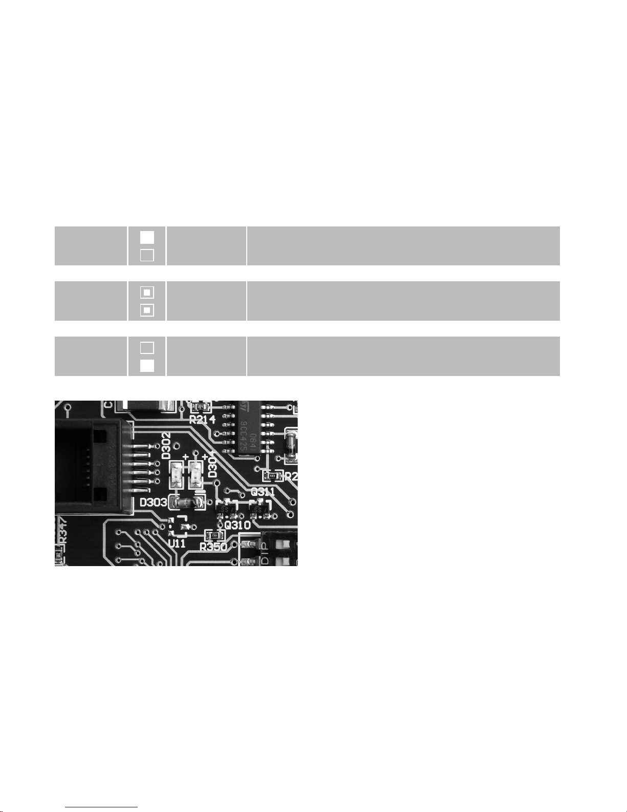
Two LEDs, D302 and D304, are located on
the control board in the solar inverter.
These describe the current status of the
solar inverter:
LED green
LED red
LED green
LED red
LED green
LED red
illuminated
off
flashing
flashing
off
illuminated
Solar inverter operating in normal mode
Solar inverter has detected an error
internal error in the control
(Fig.) LED for functional check
142
Page 57
200
3.4 Fault diagnosis
Fault display
Fault 3
DC overvoltage
Fault 4
Frequency error
Fault 5
Overheating
Causes
The maximum DC voltage
has been exceeded.
Too many modules are
connected in series.
The grid frequency is outside the permissible range.
The maximum permissible
ambient temperature of
40°C has been exceeded.
The necessary air circulation
was not taken into account
during installation.
Objects have been stored
on the heat sink, impeding
free convection.
Remedies
Check the dimensioning of your
PV generator.
Reduce the number of modules and
re-commission the system.
Ask your electricity board about grid
stability and design.
The installation location is not suitable.
Please find another installation location.
Clean the solar inverter if dirt is impeding the cooling unit.
Remove the objects.
143
Page 58

Fault display
Fault 6
Grid undervoltage,
1-phase
Fault 7
Grid overvoltage,
1-phase
Causes
The grid voltage of the fedin phase is too low.
The grid voltage of the fedin phase is too high.
Remedies
The solar inverter monitors the limits of
the minimum and maximum permissible
3-phase grid voltage. If the values fall
below these limits (U
min
= 184 V), the
solar inverter switches off and only
restarts automatically when the voltage
value has returned within the limits.
The fault cut-out can be triggered even
if the values only exceed or fall below
the limits very briefly.
Ask your electricity board about grid
stability and design.
Check the format of your grid connection
(energy counter) and the grid feed-in
point to your electricity board.
The solar inverter monitors the limits of
the minimum and maximum permissible
3-phase grid voltage. If the values exceed
below these limits (U
max
= 264 V), the
solar inverter switches off and only
restarts automatically when the voltage
value has returned within the limits.
The fault cut-out can be triggered even
if the values only exceed or fall below
144
Page 59

Fault display
Fault 8
Grid under
voltage,
3-phase
Causes
The cable cross-section in
the AC feed line to the solar
inverter is too small.
Your solar system feeds into
a spur line, which is inadequately dimensioned.
The grid voltage is
too low.
Remedies
the limits very briefly.
Ask your electricity board about grid
stability and design.
Check the format of your grid connection
(energy counter) and the grid feed-in
point to your electricity board.
The solar inverter monitors the limits of
the minimum and maximum permissible
3-phase grid voltage. If the values fall
below these limits (U
min
= 184 V), the
solar inverter switches off and only
restarts automatically when the voltage
value has returned within the limits.
The fault cut-out can be triggered even
if the values only exceed or fall below
the limits very briefly.
Ask your electricity board about grid
stability and design.
145
Page 60

Fault display
Fault 9
AFI residual current
Fault 10
Insulation error
Fault 11
DC feed
Fault 12
Isolated operation
Causes
The AFI error is displayed if
a residual current has occurred in the PV system and
the solar inverter has subsequently disconnected from
the grid.
The solar inverter has detected an insulation error
in the PV system during
startup.
The solar inverter has
detected a DC component
> 1 A in the grid current.
Dropout of monitored
phase L2 or L3.
Phase difference between
individual grid conductors
outside the permitted limit
values.
Remedies
Check the format of your grid connection
(energy counter) and the grid feed-in
point to your electricity board.
Check your PV system for possible
insulation errors.
Restart the solar inverter. If the error
still occurs, please contact the technical
hotline. You will find the telephone
number on the back of the manual.
Check phases L2 and L3.
Ask your electricity board about grid
stability and design.
146
Page 61

Fault display
Fault 13
Grid overvoltage,
3-phase
Fault 14
Surge error
Fault 15
Grid overvoltage
> 10 %
Causes
The grid voltage is too high.
The solar inverter has detected a high voltage peak
in fed-in phases.
The grid voltage of the fedin phase is too high.
Remedies
The solar inverter monitors the limits of
the minimum and maximum permissible
3-phase grid voltage. If the values exceed
below these limits (U
max
= 264 V), the
solar inverter switches off and only
restarts automatically when the voltage
value has returned within the limits.
The fault cut-out can be triggered even
if the values only exceed or fall below
the limits very briefly.
Ask your electricity board about grid
stability and design.
The solar inverter starts automatically
after fault elimination. If the error occurs
more frequently, please contact your
energy supply company.
The solar inverter monitors the limits of
the minimum and maximum permissible
grid voltage.If the limit is exceeded by
10 % (U
max
= 253 V), the solar inverter
disconnects from the grid after 10 minutes (in accordance with DIN V VDE V
0126-1-1).
147
Page 62

Fault display
Fault 16
Control error
Causes
The cable cross-section in
the AC feed line to the solar
inverter is too small.
Your PV system feeds
into a stub line which is too
weakly dimensioned.
The intrinsic monitoring
of the solar inverter has
detected an error in the
control.
Remedies
Ask your electricity board about grid
stability and design.
Check the format of your grid connection
(energy counter) and the grid feed-in
point to your electricity board.
Please contact the technical hotline.
You will find the telephone number
on the back of the manual.
148
Page 63

Fault display
Incorrect time,
date are stored
in Sunways NT
Monitor with
incorrect time
data
No data
displayed, sufficient irradiation
Causes
The battery is empty.
The display contrast is poor
on account of high temperature.
The display board is not
receiving any voltage
supply.
The PV generator is
(partially) covered with
snow.
Remedies
Have the battery (button cell) replaced
by an expert. The battery is located on
the LCD display board.
This can occur with high ambient temperatures. The display will operate normally
again when the temperature decreases.
The current feed is not affected by this.
Check that the flat cable between display
and control board is firmly located.
To do this, switch off the solar inverter
and isolate on the DC and AC sides.
Clear the snow from the PV generator
or wait until the snow has thawed.
149
Page 64

150
3.5 Warranty terms and conditions
· Warranty period
The warranty period is five years from
purchase of the solar inverter by the end
user. Please complete the enclosed warranty card and return it to Sunways AG.
Please keep the original invoice with the
date of purchase in a safe place. This will
be required as proof, in addition to the
warranty card, in the event of a claim.
· Conditions
During the warranty period, the solar
inverter will be repaired free of labour
and material costs in Constance. Installation costs are borne by the customer,
unless agreed otherwise. The completed
warranty card must be sent to Sunways
AG, Constance within seven days of
purchase.
Please notify us of any warranty claims
by telephone stating your name,
address, telephone and serial number,
and your email address if applicable.
You will find the telephone number on
the back of the manual.
Sunways AG must be allowed the necessary
time to eliminate the defect. Sunways AG
will endeavour to eliminate the defect
within 14 days of receipt of the unit. If this
is not possible, the customer will be informed of the reason and the time when the
defect will be eliminated will be specified.
Please preserve the original packing,
even after expiry of the warranty period.
Carriers may only accept solar inverters in
transport-safe original packing. Therefore,
please inform us before collection if you
have lost the original packing. We will
gladly provide you with new packing for
a charge.
Page 65

EN
151
· Exclusion of liability
Warranty claims and liability are excluded
for direct or indirect damages due to:
· Interventions, modifications or attempted
repairs
· Inadequate ventilation
· Force majeure (e.g. lightning strike, water
damage, vandalism, fire, overvoltage,
thunderstorms etc.)
· Inappropriate transport
· Non-observance of pertinent regulations
or incorrect installation or commissioning
· Leakage of overvoltages from the varistors on the DC side on the PV generator
More extensive or other claims for direct
or indirect damages, particularly claims
for damages, including those arising from
positive contract violation, are excluded,
unless legally prescribed.
Page 66

4.0 Appendix
152
Page 67

4.1 Subject and abbreviation index
EN
153
Designation
AC
AFI, RCD
DC
EMC
EB
I
NDC
IP
kW
LCD
MPP
Description
Alternating Current: grid current
Operator protection in the event of residual currents
AFI: Universal Sensitive Residual Current
RCD: Residual Current Device
Direct Current
PV generator side of the solar inverter
Electromagnetic Compatibility
Electricity Board
Current used to operate the solar inverter
Identification of class of protection against external
environ-mental influences (penetration of water and
mechanical foreign bodies)
Kilowatt
Liquid Crystal Display
Maximum Power Point
Page 68

154
Designation
Grid impedance
P
NDCPNAC
PT
PV
PV generator switch
U
NDC
Description
AC resistance of grid, impedance
DC and AC rated power:
Power which the inverters can permanently consume
(DC) or emit (AC).
Temperature sensor
Photovoltaic
DC load break switch to cut off the PV generator from
the solar inverter
Voltage: specifies the normal operating voltage at which
the solar inverter is operated
Page 69

EN
155
4.2 Function and information index
Functional principle and explanations
The electrical energy of the PV generator
is buffered by a capacitive storage, from
where it is fed into the public grid via a
solar inverter synchronised with the grid,
with an ideal phase angle of [cos phi = 1].
A sinusoidal current with a very low harmonic distortion is injected into the public
grid by the current injection inductor. This
improves the grid quality.
Thanks to the HERIC
®
technology (patent
applied for) in the self-commutated
Sunways Solar Inverter, the hysteresis losses
in the current injection inductors that
occur in conventional solar inverters and
the switching losses in the semiconductors
are considerably reduced. Consequently,
Sunways Solar Inverters achieve a peak
efficiency during conversion. The concept
of the Sunways Solar Inverter is completed
by a rapid MPP control, which maintains
the MPP point with a very high adaptation
efficiency.
· DC and AC filters
The DC and AC filters are specially designed
EMC filters, which are integrated as direct
components on the board. They guarantee
compliance with the EMC limit values on
the AC side and on the PV generator side.
High-frequency emissions are avoided by
the filters on the PV generator side.
· Differential measurement
The generator current and the voltage are
recorded via a current transformer and a
differential measurement. The values are
important input values for the regulation
and setting of the correct working point.
· Solar inverter with HERIC
®
technology
The heart of the solar inverter with the
power semiconductors serves for conversion of the current from direct into
alternating current. Peak efficiencies are
achieved, thanks to the HERIC
®
technology. The switching frequency (PWM) is
16 kHz.
Page 70

156
· Sensor interface
An irradiation sensor with integrated
temperature sensor can be optionally connected to the relevant interface. This
allows first time users to quickly grasp the
mode of functioning of their PV system,
and facilitates monitoring of the PV
system for professionals.
· AFI universal sensitive residual current
device
The universal (DC and AC) sensitive residual current device (AFI) monitors the solar
system for residual currents. To do this,
it disconnects the solar inverter from the
grid by means of a relay as soon as a residual current occurs on the PV generator
side or on the AC side in the solar inverter.
After cutoff by the relay and as soon as
the residual current has stopped, the AFI
automatically attempts to reconnect the
solar inverter to the grid. The AFI of the
Sunways solar inverter complies with
standard DIN V VDE V 0126-1-1.
In addition, the AFI of Solar Inverters
NT 6000, NT 5000, NT 4000 and NT 2600
has an absolutely time-independent
· Grid protection
The grid protection is a powerful relay
which ensures reliable grid disconnection
in the case of error and for night switchoff. This relay fulfils the requirement for
trouble-free grid disconnection.
· Microcontroller
As well as system management, the
efficient microcontroller undertakes
additional tasks, such as saving data
and communication.
· LCD display
Important information for the operator
about the system operation and status is
displayed on an LCD display of 2 x 16
characters.
· RS 485 and RS 232 interfaces
The two RS 485 and RS 232 interfaces
installed as standard serve for communication with the solar inverter and the PV
system. The system can be visualised via
the Sunways NT Monitor software.
Page 71

EN
157
effective value cutoff threshold. The solar
inverter is switched off and isolated from
the grid in the case of an error current of
≥ 300 mA.
· MPP control
The solar inverter has a rapid MPP control,
which maintains the MPP point with a very
high adaptation efficiency. If surplus power
is provided by the PV generator, the solar
inverter limits this by shifting the working
point of the characteristic curve of the PV
generator, so as not to exceed the maximum permissible AC feed-in power in
accordance with VDEW.
Page 72
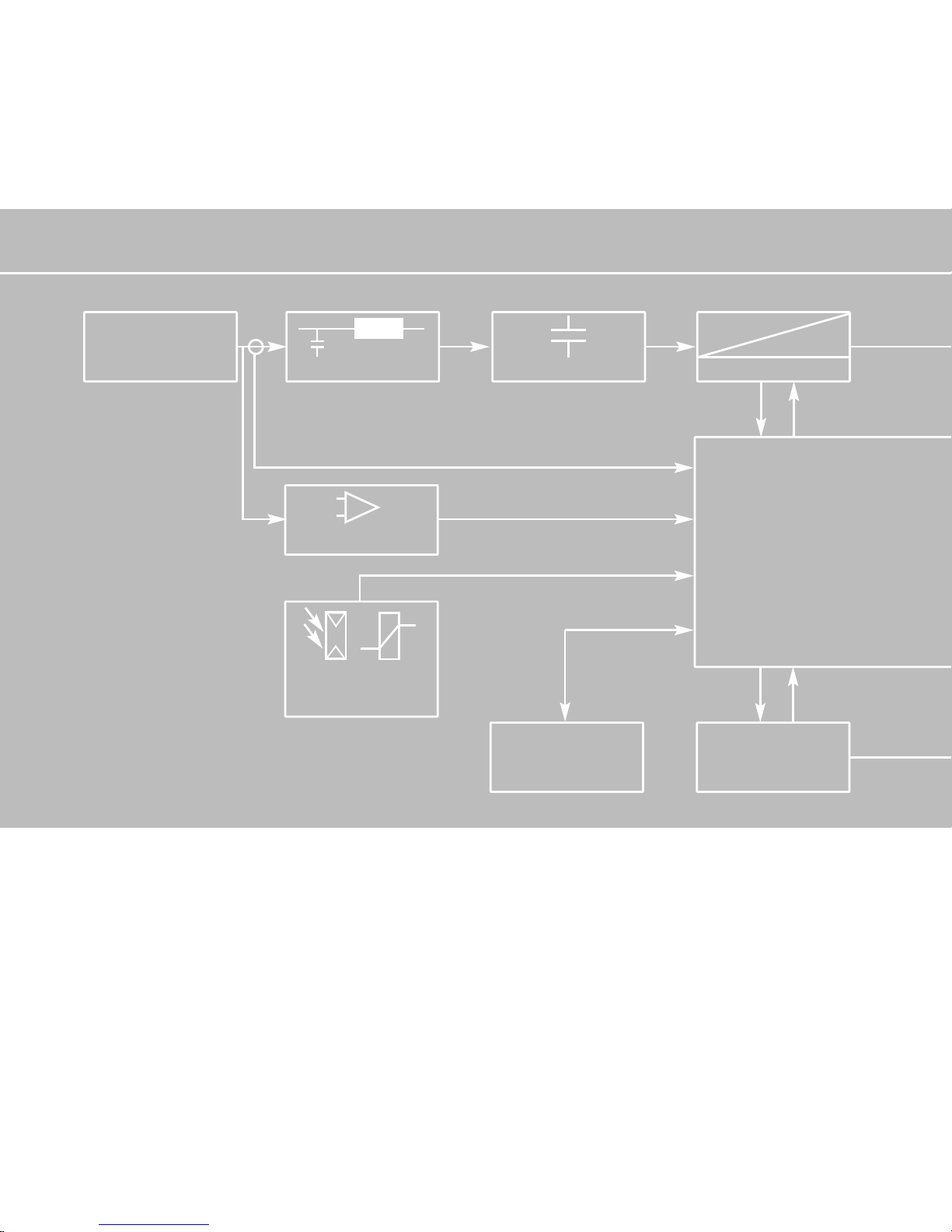
DC FILTER
CAPACITIVE STORAGE
Block diagram of the solar inverter in the PV system
HERIC
®
=
≈
DIFFERER. MEASUREMENT
R
T
IRRADIATION SENSOR AND
TEMPERATURE SENSOR
(OPT.)
RS 232
RS 485
MICRO-
CONTROLLER
CONTROL
DATAPRO
TEMP CONTROLLER
I
DC
U
DC
RADIATION
AND
TEMPERATURE
DATA
PV GENERATOR
158
Page 73

CURRENT IMPRESSION
INDUCTOR
AC FILTER GRID PROTECTION
RESIDUAL CURRENT
AFI
DIFFERER. MEASUREMENT
LCD-DISPLAY
(2 LINES)
KEYBOARD
AND
CESSING
AFI
U
AC
I
AC
GRID
L1, N, L2,L3,
PE
159
Page 74
Technical data
Solar Inverter NT 2600
Recommended solar generator power
Rated input power
Stand-by consumption
Night-time consumption
AC energy generated from
Nominal voltage
U
MPP
voltage range
Open-circuit voltage
Switch-on voltage
Switch-off voltage
Maximum current
Nominal current
Number of inputs
Maximum efficiency
European efficiency (weighted)
HERIC
®
topology
Rated continuous output power Pn
Maximum power Pp
Nominal frequency
Grid voltage
Nominal current
Maximum current
Distortion factor at Pn
Reactive power factor (cos phi)
Output current
Model
1500 to 2750 W
2300 W
9 W
< 0,15 W
15 W
400 V
350 ≤ U
MPP
≤ 750 V
850 V
410 V
340 V
7 A
5,75 A
2 (with adapter: 4)
97 per cent
96,5 per cent
yes
2200 W
2200 W
50 Hz
230 V
9,6 A
9,6 A
< 3 per cent
~1
sinusoidal
DC
AC
160
Page 75
Solar Inverter NT 4000 Solar Inverter NT 6000
2000 to 4125 W
3400 W
9 W
< 0,15 W
15 W
400 V
350 ≤ U
MPP
≤ 750 V
850 V
410 V
340 V
10 A
8,5 A
2 (with adapter: 4)
97 per cent
96,4 per cent
yes
3300 W
3300 W
50 Hz
230 V
14,3 A
14,3 A
< 3 per cent
~1
sinusoidal
4000 to 6250 W
5200 W
9 W
< 0,15 W
15 W
400 V
350 ≤ U
MPP
≤ 750 V
850 V
410 V
340 V
18 A
13 A
2 (with adapter: 4)
97 per cent
96,3 per cent
yes
4600 W
5000 W
50 Hz
230 V
20 A
21,7 A
< 3 per cent
~1
sinusoidal
Solar Inverter NT 5000
3000 to 4800 W
4300 W
9 W
< 0,15 W
15 W
400 V
350 ≤ U
MPP
≤ 750 V
850 V
410 V
340 V
13 A
10,8 A
2 (with adapter: 4)
97 per cent
96,4 per cent
yes
4000 W
4200 W
50 Hz
230 V
17,4 A
18,3 A
< 3 per cent
~1
sinusoidal
161
Page 76

Grid voltage monitoring
Earth fault protection
Isolation, Frequency and DC-Current Monitoring
Output characteristic
Grid connection fuse layout
Required number of grid connection phases
Number of feed-in phases (230 V single-phase)
Data interfaces
Sensor interfaces
Display
System of protection against envir. influences
Relative air humidity, max.
Cooling
Ambient temperature (Celsius)
Dimensions (height x width x depth)
Weight
Noise development
Standard warranty period (option)
threephase
RCD (universally sensitive)
integrated
current source
16 A
3
1
external RS 232, RS 485,
status signal relay
irradiation, temperature
LCD, 2 x 16 characters
IP 54
95 per cent
free convection
-25°C to 40°C
515 x 300 x 190 mm
26 kg
silent (< 35 dB (A))
5 years (10 years)
162
Page 77

threephase
RCD (universally sensitive)
integrated
current source
25 A
3
1
external RS 232, RS 485,
status signal relay
irradiation, temperature
LCD, 2 x 16 characters
IP 54
95 per cent
free convection
-25°C to 40°C
515 x 300 x 190 mm
26 kg
silent (< 35 dB (A))
5 years (10 years)
threephase
RCD (universally sensitive)
integrated
current source
25 A
3
1
external RS 232, RS 485,
status signal relay
irradiation, temperature
LCD, 2 x 16 characters
IP 54
95 per cent
free convection
-25°C to 40°C
515 x 300 x 190 mm
26 kg
silent (< 35 dB (A))
5 years (10 years)
threephase
RCD (universally sensitive)
integrated
current source
25 A
3
1
external RS 232, RS 485,
status signal relay
irradiation, temperature
LCD, 2 x 16 characters
IP 54
95 per cent
free convection
-25°C to 40°C
515 x 300 x 190 mm
26 kg
silent (< 35 dB (A))
5 years (10 years)
163
Page 78
Tyco Solarlok connector
The Tyco Solarlok connectors are only
approved for connection to permanently
laid cables!
They must not be disconnected under
load!
The circuit must be interrupted at a suitable point! The cables must be provided
with a suitable adhesive label close to
the Tyco Solarlok connector!
The Tyco Solarlok connectors must
always be disconnected from other voltage sources on all sides during assembly, in order to protect against electric
shock.
!
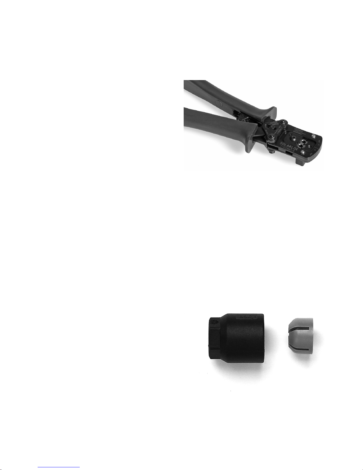
(Fig.) Manual crimping tool for assembly of
Tyco Solarlok connectors
(Fig.) Tyco Solarlok connectors
164
Page 79
Any type of soiling (dust, humidity etc.)
will negatively affect the operation of the
system over the desired period of use. This
applies particularly for the usability of the
seals and crimping of the contacts. The
utmost care must therefore be taken to
work cleanly during installation.
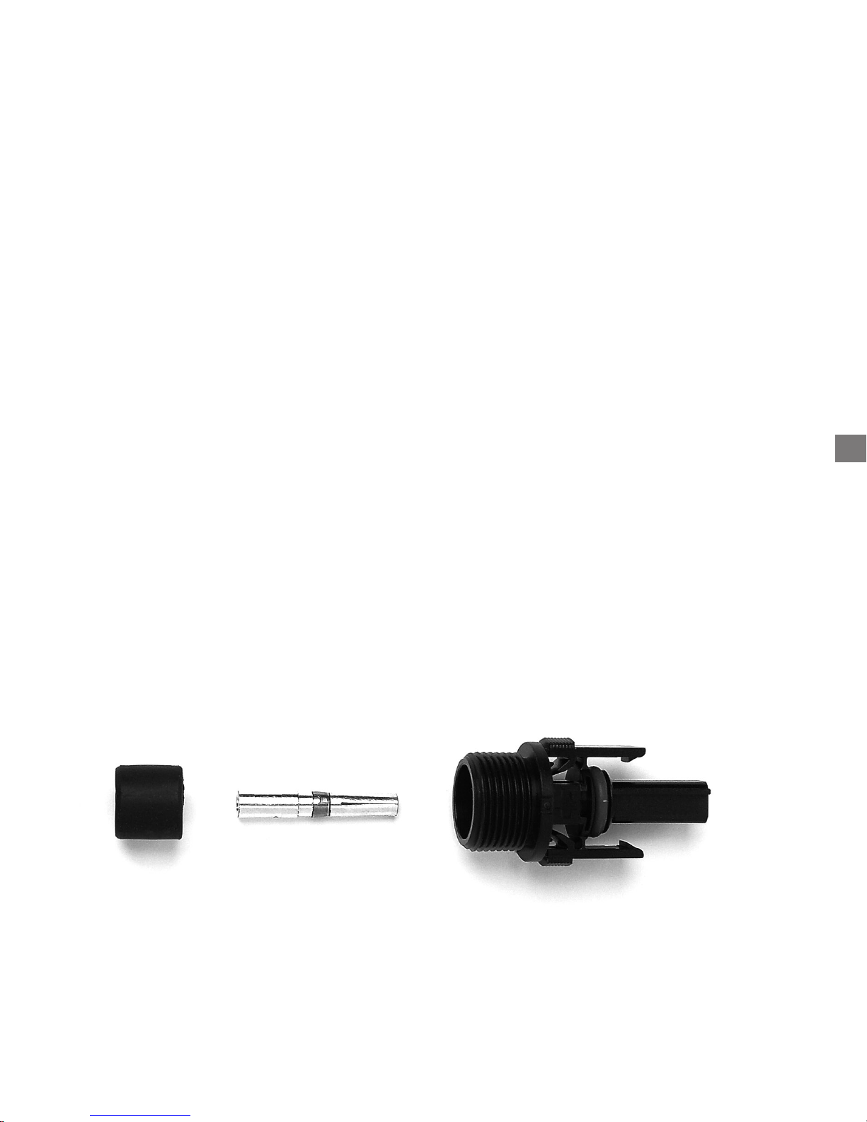
Different circular contacts are used for different conductor cross-sections for the Tyco
Solarlok connectors. The correct tool insert
must be used, depending on this cross-section. The enclosed Tyco Solarlok connectors
are equipped with circular contacts for a
cable cross-section of 4 mm. The enclosed
seals have internal dimensions of 6 (for
cables of 5.3 to 6.2 mm sheath diameter)
and 8 mm (for cables of 7.2 to 8.0 mm sheath diameter). The seal must be matched
to the sheath diameter of the cables used.
EN
The following sequence must be observed
for assembly of Tyco Solarlok connectors:
1. Strip the voltage-free cable by 8 mm.
2. Crimp on the circular contact.
3. Push the cable gland, clamping piece
and seal onto the cable.
4. Engage the contact in the connector
housing.
5. Screw on the clamping nut.
6. Tightening torque of the threaded
cable gland is 1.5 Nm.
165
Page 80

166
Declaration of Conformity as per EG Low Voltage Guidelines 73/23/EWG,
attachment III B
We herewith declare that the following product including the required accessories has
been manufactured according to the EG guidelines 73/23/EWG and 93/68/EWG:
Product
Manufacture
Type
From date of manufacture
Applied standards
Standard
Title
Edition
Solar Inverter
Sunways AG, Photovoltaic Technology
Macairestr. 3-5, D - 78467 Konstanz
Sunways NT 6000, NT 5000, NT 4000, NT 2600
2005-05-02
EN 50178
Electronic equipment for use in power installations
1998
Explanation
This product is a component intended for further assembly. Due to the features resulting therefrom, the product cannot initially
meet requirements made of finished products, machines or plants. It must thus be used for mounting / assembly only.
An evaluation of electrical and mechanical safety and of environmental conditions (e.g. extrinsic objects and / or humidity) must
be performed after mounting / assembly in the finished plant.
The EMC characteristics of this product can change in a mounted / assembled state. An EMC check must thus be made for the
PV-System by the manufacturer of the PV-System.
City, Date Roland Burkhardt,CEO
Konstanz, 2005-03-05
Page 81
EN
167
Declaration of Conformity as defined by the EMC guideline 89/336/EWG with
revisions 91/263/EWG and 93/68/EWG.
We herewith declare that the following product has been manufactured according to
the requirements outlined in the EG requirements on 89/336/EWG (EMC guideline with
revisions 91/263/EWG)
Product
Manufacturer
Type
from date of manufacture
applied standards
Standard
Solar Inverter
Sunways AG, Photovoltaic Technology
Macairestr. 3-5, D - 78467 Konstanz
Sunways NT 6000, NT 5000, NT 4000, NT 2600
2005-05-02
EN 50082-2 (EN 61000-4-2, -4-3, -4-4, -4-6, -4-8)
EN 55014-1; EN 55011; EN 61000-3-2;
EN 61000-3-3; E DIN VDE 0126-1-1
Explanation
Maintaining the EMC guideline assumes an EMC adapted installation of the component within the plant or the machine.
Please pay attention to the installation notes of the technical specifications. Tests were carried out using a typical construction in
a test assembly that conforms with the stands. The legal requirements with regard to resistance to interference and to emission
of interference, limit values and standards are outlined in the above mentioned documentation.
These Sunways products are intended for installation into a PV-System. The test results are not applicable to every installed state
in every PV-System. This declaration therefore does not guarantee the EMC characteristics of the end product.
City, Date Roland Burkhardt,CEO
Konstanz, 2005-03-05
Page 82

168
Declaration of Conformity of nominal power and maximum output
power of solar inverters.
Product
Manufacturer
Type Sunways
Nominal power S
N
Maximum output power S
max10Min
S
max10Min/SN
Solar Inverter
Sunways AG, Photovoltaic Technology
Macairestr. 3-5, D - 78467 Konstanz
Explanation
The maximum output power of the solar inverter has to be declarated as a max. 10 minute average.
City, Date Roland Burkhardt,CEO
Konstanz, 2005-22-03
NT 4000
3,3 kVA
3,3 kVA
1
NT 2600
2,2 kVA
2,2 kVA
1
NT 6000
4,6 kVA
5 kVA
1,08
NT 5000
4,0 kVA
4,2 kVA
1,05
Page 83
EN
169
Declaration of Conformity as defined by the guidelines for connection
and grid feeding in parallel of in-plant generation on low-voltage-guidelines
(VDEW 4. Edition 2001).
We herewith declare that the following product has been manufactured according to
the requirements outlined in the guidelines for connection and grid feeding in parallel
of in-plant generation on low-voltage-guidelines:
Product
Manufacturer
Type
From date of manufacture
Applied standard
Standard
Title
Edition
Solar Inverter
Sunways AG, Photovoltaic Technology
Macairestr. 3-5, D - 78467 Konstanz
Sunways NT 6000, NT 5000, NT 4000, NT 2600
2005-05-02
In-plant generation on low-voltageguidelines
4. Edition 2001
Explanation
The NT series of solar inverters from Sunways are monophase inverters that are not capable of isolated operation. They are
equipped with a voltage monitor and three phase monitoring of the line voltage for undervoltage in accordance with section
2.4.2 of the VDEW Guideline (4th edition 2001). A constantly accessible isolation point is therefore not required (see section
2.1.2 Switching point with isolating function). Observation of the cut-off values of the threephase undervoltage protection
is undertaken by means of a routine check test on each device
City, Date Roland Burkhardt,CEO
Konstanz, 2005-22-03
Page 84

170
General exclusion of liability
Although the accuracy and completeness
of the information contained in these
instructions have been checked with the
utmost care, no liability can be accepted
for errors or omissions.
· Sunways AG reserves the right to modify
the hardware and software features
described here at any time, without
prior notice.
· These instructions may not be duplicated, passed on, copied or translated in
to other languages, either in whole or
in part, in any form or by any means,
without prior written permission of
Sunways AG.
· Sunways AG does not provide any warranty for damages due to defective or
lost data, incorrect operation or malfunctioning of the solar inverter, the
software, additional equipment or PCs.
All rights reserved. © Sunways AG
The products specified in the title are
copyright-protected and are sold with
licences. No part of this document may
be reproduced in any form, without prior
written permission of Sunways AG and
the Sunways licensors.
Registered trademarks
Sunways Sunways NT 6000, NT 5000, NT
4000 and NT 2600 and the Sunways logo
are registered trademarks of Sunways AG,
Constance.
HERIC
®
is a registered trademark of
Fraunhofer, Munich.
Page 85

200
Page 86

Sunways AG
Photovoltaic Technology
Macairestraße 3 - 5
D-78467 Konstanz
Telefon + 49 7531 996770
Fax + 49 7531 99677444
E-Mail info@ sunways.de
www.sunways.de
Technische Hotline +49 7531 99677577
9-1-27-0-0 Version 05/05
 Loading...