

Page 1
1
User Manual
Sunways Solar Inverter
NT 2500, NT 3700, NT 4200,
NT 5000
english
EN
Page 2

2
Imprint
All rights reserved.
© Copyright by:
Sunways AG
Photovoltaic Technology
Macairestraße 3 - 5
78467 Konstanz
Germany
This user manual may only be reprinted or copied in whole or in part with the express, written approval of
Sunways AG. Any type of reproduction, distribution or storage on data carriers in any form and of any kind
not authorised by Sunways AG represents a violation of the applicable copyright laws and will be prosecuted.
We reserve the right to make technical changes which serve to improve the device, or which increase the
safety standard – even without separate prior notice.
Publisher responsible for the content: Sunways AG
This user manual contains products and product names which are registered trademarks. The mention of
products and product names is used only for information purposes and does not represent
product misuse. The passage referring to these products in this user manual does not represent original documentation of the respective product.
Page 3

Introduction
Thank you for deciding in favour of a Sunways Solar
Inverter of the NT series!
In doing so you have purchased an innovative, highquality product with unique equipment features
and a high, constant efficiency. This Solar Inverter is
equipped with HERIC
®
topology and therefore enables operation on a large number of solar modules
– as accustomed from Sunways – without the use of
a transformer.
This user manual contains explanations on using the
Sunways Solar Inverter. You will learn to recognise
the many possibilities of the Solar Inverter. Information is provided on safety, installation, commissioning, operation and system monitoring.
Please observe the safety precautions exactly to
ensure increased safety at the operating site of the
Solar Inverter.
Page 4

4
Content
1 Product description 7
1.1 Proper use 7
1.2 Function description 7
1.3 Integration in solar system 8
Design of solar generator 8
Standard components of a solar system 9
1.4 Assembly description 9
1.5 Delivery scope 10
2 Safety precautions 11
2.1 General safety precautions 11
2.2 Explanation of symbols and warnings 12
Warnings and symbols used in this user
manual 12
Symbols used in this user manual 12
Warnings and symbols on device 12
2.3 Basic safety measures 13
2.4 Safety concept 13
3 Installation 14
3.1 Mechanical installation 14
Requirements for installation location 14
Installation 15
3.2 Electrical installation 16
Solar generator connection 16
Grid connection 20
3.3 Installing communication 22
Interface overview 22
Networking Solar Inverters via CAN bus 23
Networking Solar Inverters via RS485
interface 25
S0 interface 26
Connection of temperature and irradiation sensor 26
Connecting alarm relay 27
Page 5

Content
5
4 Commissioning 28
4.1 Connecting and disconnecting Solar
Inverter 28
Connecting 28
Switching off 28
4.2 Commissioning 29
Commissioning single device 29
Commissioning several networked devices 30
Later commissioning 34
5 Operation 35
5.1 Operating elements 35
Operating field 35
LCD display 35
Operating LED 35
Standard screen (single device) 36
Standard screen (system) 37
5.2 Access rights 37
Customer area 37
Installer area 38
Country password 38
5.3 Menu structure 39
5.4 Overview of screen displays 40
5.5 Malfunction displays 48
Solar generator fault 48
AC network fault 49
Inverter fault 51
Interface/communication fault 53
Communication warnings 54
Service fault 56
6 System monitoring 57
6.1 General information 57
6.2 Integrated data logger 57
6.3 Direct Ethernet connection 58
6.4 Network settings on Solar Inverter 59
6.5 Network settings on the PC 60
6.6 Connection via an existing Ethernet
network 62
Page 6

Content
6
6.7 Remote access via a DSL router 63
6.8 Connection via the Sunways Modem 63
6.9 Dial-up connection from a PC to the
Solar Inverter 64
7 Sunways Browser 67
7.1 General information 67
7.2 Access protection 67
7.3 Overview – Menu 68
7.4 Language selection 68
7.5 Setting the date/time 69
7.6 Software update 69
7.7 Internet dial-up via modem 70
Modem settings 70
E-mail settings 71
7.8 Active alerting 72
General information 72
Alerting settings 73
7.9 Sunways Portal connection 73
General information 73
Setup 74
8 Appendix 75
8.1 Technical data 75
8.2 Drilling template for wall bracket 77
8.3 General liability disclaimer 78
Page 7

7
1 Product description
1.1 Proper use
The Sunways NT Solar Inverter is the link between
your solar generator and the public power grid.
The energy from the connected solar generator is
converted to grid-conformant AC current and fed
into the grid.
Solar modules which require earthing of the negative or positive terminal cannot be operated with
the NT Solar Inverter. If in doubt, always ask your
module manufacturer about a release!
1.2 Function description
Conversion from direct into alternating current
The NT Solar Inverter converts the direct current
produced by the solar generator into alternating
current. The alternating current is fed into the public power grid as a single-phase current.
Operating and display elements
Various interfaces are available for system configuration and monitoring:
· Operating field (LCD display and keyboard) for
displaying operating and status values or for
inputting system parameters
· Operating LED
· Integrated web server for display and configuration via a web browser
Interfaces
· Bus interface for connecting an analogue
modem, ISDN modem or GSM/GPRS modem
· Ethernet interface for connecting a PC or for
integration in existing networks
· CAN bus interface for interconnecting several
Solar Inverters
· S0 pulse output for controlling large displays
· Alarm relay for realising simple monitoring
locally
· Interface for connecting an irradiation and temperature sensor
Data logging
The NT Solar Inverter is equipped with internal data
logging for recording and saving system data:
· 5-minute mean values of voltages, currents,
output, temperature and irradiation (if sensor is
installed)
· 5-minute, daily, monthly and annual values of
energy yield
· 5-minute maximum and minimum values for AC
output, irradiance, system output
· Memory for malfunction messages
Grid monitoring
The NT Solar Inverter assumes the task of grid monitoring for the protection of the device and persons.
In case of abnormal grid conditions, feeding is
immediately interrupted and the Solar Inverter disconnects from the grid by triggering the grid relay.
Functions resulting from the German Renewable
Energy Act and the Medium- and Low-Voltage
Directive
The Solar Inverter hardware already meets the
requirements of the new Medium- and Low-Voltage
Directive and will support all functions via software
update by the end of the transitional period.
Output control through the PSC according to the
2009 amendment of the German Renewable Energy
Act can be realised via the Power-Control Box
accessory.
Design of Solar Inverter
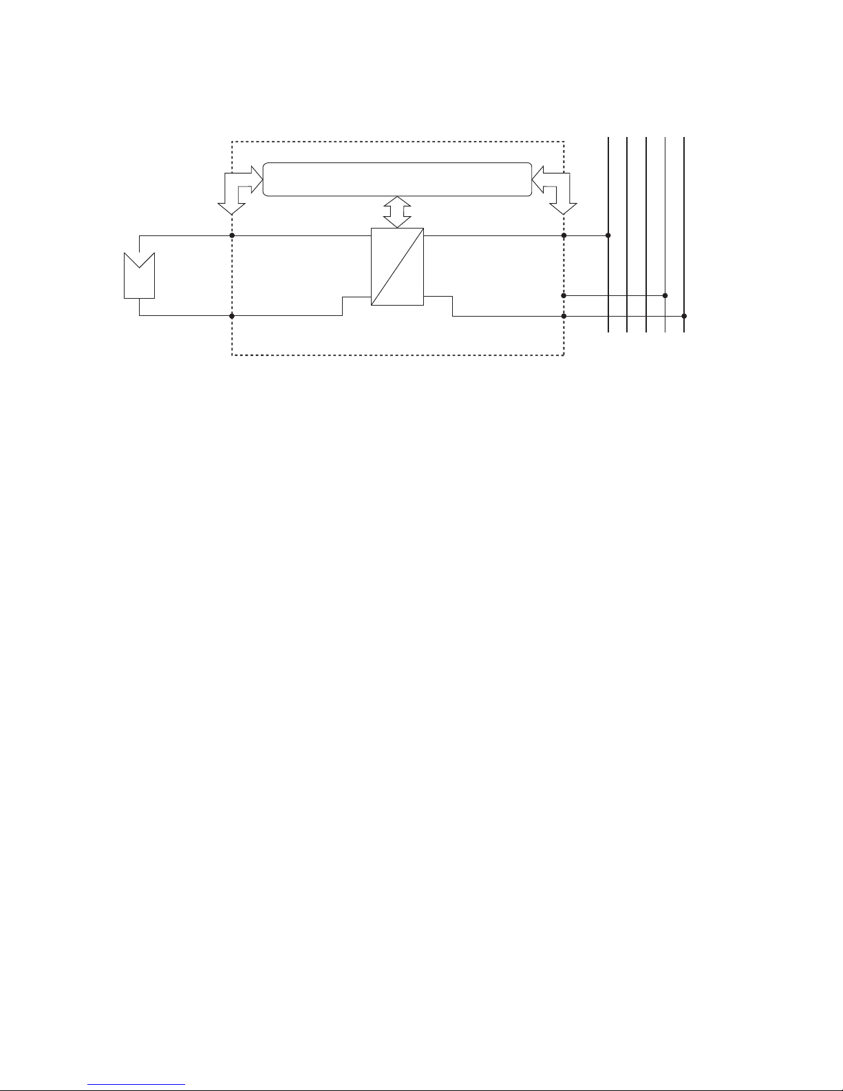
The principle design of the NT Solar Inverters can be
recognised from the block diagram (page 8).
Page 8
1 Product description
8
Block diagram
=
~
L1
PE
N
L1 L2 L3 PE N
–
+
Control and monitoring
HERIC
®
inverter
Solar generator
Grid
DC+
DC–
1.3 Integration in solar system
Design of solar generator
The technical data of the selected solar generator
must be within the Solar Inverter‘s specifications
(see Technical Data). Incorrect dimensioning can
lead to reductions in the yield and to destruction of
the device.
The design program Sunways Sundim may be helpful to you. Sunways Sundim is available on the
included CD-ROM or at our homepage
www.sunways.de.
Be sure to take the following points into account
before planning your system:
· Watch the celestial alignment of the modules.
A maximum yield is achieved in Central Europe
with a module slope of 30° to the vertical and
direction of the solar generator field directly to
the south.
· The output of the cells decreases as the module
temperature increases. Install your solar generator with sufficient ventilation from behind.
· Check your solar generator approx. every three
years for soiling. This occurs especially on the
lower edge of the modules and forms a veil
that cannot be washed off even by heavy rain.
Reduced yield can be prevented by cleaning with
a wet cloth or a brush.
· Avoid switching off individual modules or solar
cells of your system. This can lead to major
decreases in yield.
Page 9
1 Product description
9
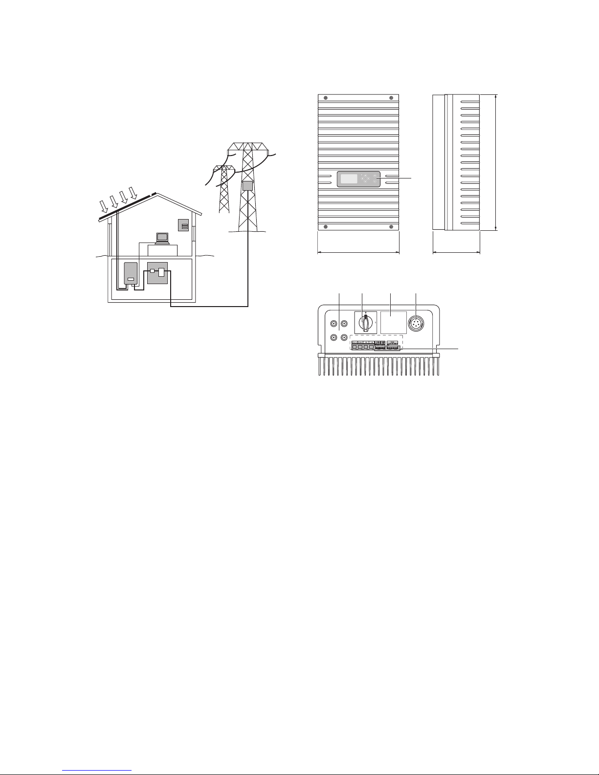
Standard components of a solar system
Depending on the recommendations of your PV
planning expert, your PV system consists of the following components:
1
4
5
2
3
6
DC
AC
1 Solar generator
2 Solar Inverter with integrated DC load break
switch
3 Mains fuse and energy meter
Options
4 Irradiation sensor with integrated temperature
sensor
5 PC for monitoring system
6 Large display
1.4 Assembly description
+–
+–
1
2
350
585
205
2 3 4 5
6
1
Solar Inverter NT 5000
1 Operating field with LCD display, operating LED
and keyboard
2 DC connections
3 DC load break switch
4 Rating plate
5 AC connection
6 Communication interfaces
Page 10

1 Product description
10
1.5 Delivery scope
The delivery consists of:
· Sunways Solar Inverter of the NT-Series
· Wall bracket
· 2 pairs of Tyco Solarlok plug-in connectors
· AC connector
· CAN terminating resistor connector (connected)
· Ethernet cable, 2 m (CAT 5e, 1:1)
· Warranty registration
· SETUP - quick reference guide
· CD-ROM, including: Manual, Sunways Sundim
design program, product and service information
Checking delivery
Before shipment our products are checked for
proper condition. Despite careful, recyclable packing, transport damage may occur, for which the
transport company is generally responsible.
Please check the delivered Solar Inverter thoroughly!
Should you discover damage to the packing or the
Solar Inverter, please inform the transport company
immediately. Your specialist dealer will be happy to
support you if necessary. A possible damage report
must always be received by the transport company
in writing at the la-test seven days after receipt of
the goods.
Page 11

11
2 Safety precautions
2.1 General safety precautions
Observe information in operating manual!
The condition for the safe handling and malfunction-free operation of the NT Solar Inverter is a
knowledge of the basic safety precautions.
This user manual contains the most important information on operating the system safely.
Each person concerned with the installation, commissioning, maintenance and operation of the Solar
Inverter must have read and understood the entire
user manual, and in particular the chapter entitled
Safety Precautions.
In addition, the rules and regulations for accident
prevention applicable for the operating site/plant
must be observed.
Dangers when handling the NT Solar Inverter
The Solar Inverter has been built in accordance with
the latest rules of techno-logy and the recognized
safety rules and may only be used
· for its intended use
· when in proper condition with regard to safety.
Improper use may lead to dangers to the life and
limb of the user or others, or can adversely affect
the system or other property.
In case of malfunctions which can impair safety, the
system must be shut down immediately and secured
against being switched on again. The malfunction
must then be eliminated immediately.
Warranty and liability
The Sunways AG „General Terms and Conditions of
Sale and Delivery« always apply. Warranty and liability claims for personal injury or damage to property
are excluded, if they were caused by one or more of
the following:
· Improper use of the Solar Inverter
· Improper installation, commissioning, operation
and maintenance
· Operation of the Solar Inverter with defective
and/or non-operational safety and protective
equipment
· Failure to observe the information in the user
manual regarding installation, commissioning,
operation and maintenance
· Unauthorised constructional modifications
· Insufficient monitoring of wearing parts
· Improperly conducted repairs
· Emergencies caused by external influence or
force majeure
Page 12
2 Safety precautions
12
2.2 Explanation of symbols and warnings
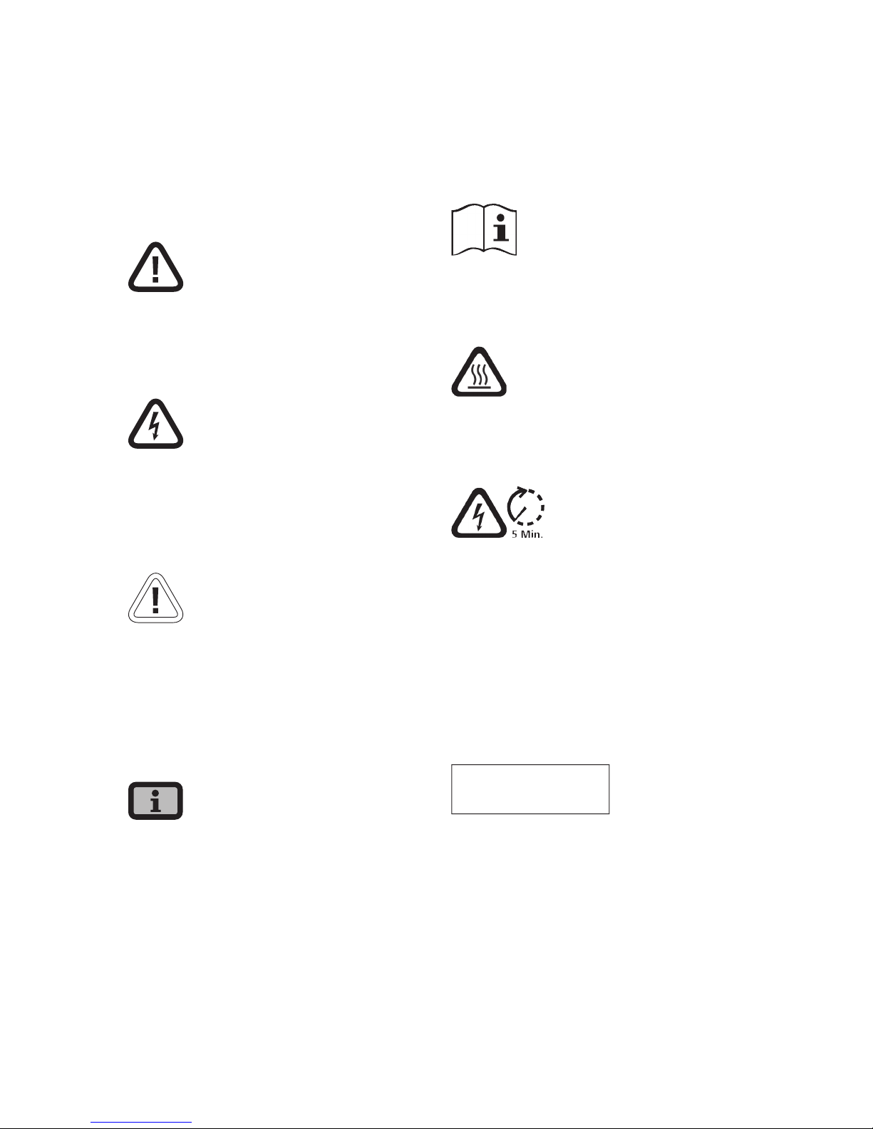
To help you quickly understand this manual and
safely use the Solar Inverter, the following warnings
and symbols are used.
Warnings and symbols used in this user manual
DANGER
This symbol indicates an immediate danger which
will result in death, injury or serious damage if the
applicable safety regulations are not followed.
Extreme danger from electric shock!
This symbol indicates an immediate danger from
electric shock which will result in death, injury or
serious damage if the applicable safety regulations
are not followed.
CAUTION
This symbol indicates an immediate danger which
can result in damage if the applicable safety regulations are not followed.
Symbols used in this user manual
Information
This symbol indicates important information which
contributes to a better understanding of the Solar
Inverter.
Warnings and symbols on device
The following warnings on the housing of the Solar
Inverter point out dangers. Always observe the
warnings exactly.
This symbol indicates that the user manual must be
read and understood before putting the device into
operation.
IMPORTANT
Hot surface! The housing can heat up during
operation.
The device must be disconnected from the mains
supply and from the PV generator before opening
the housing. The device still carries life-threatening
voltage for approx. five minutes internally and at
the connection terminals of the PV generator following disconnection from the PV generator. The
energy storage capacitors are not completely discharged until after this time. You must wait at least
five minutes after disconnecting the device from
the mains supply and from the PV generator before
opening the device.
Warning!
High leakage current,
earth connection essential before
connecting supply.
WARNING!
High leakage currents. Be sure to make an earthing connection before connecting the power supply
circuit (AC system).
Page 13

2 Safety precautions
13
2.3 Basic safety measures
Electrical work on the Solar Inverter must be conducted by a qualified electrician while observing the
VDE regulations, national and other regulations.
The Solar Inverter may only be opened by persons
authorised by Sunways AG to do so.
When circuit breakers are tripped, the fault cause
must be determined and eliminated before returning the device to operation.
Check electrical equipment regularly.
Retighten loose connections.
Replace damaged lines/cables immediately.
2.4 Safety concept
The following parameters are monitored and
displayed continuously and simultaneously by the
inverter controller:
· DC overvoltage
· Overvoltage L1, L2, L3
· Undervoltage L1, L2, L3
· Isolated operation
· Over- / underfrequency L1
· Surge error (brief overvoltage L1)
· DC share in AC current
· AFI residual current
· Overtemperature of heat sink
When a malfunction occurs, feeding is immediately
interrupted and the Solar Inverter disconnects from
the grid by triggering the grid relay.
The potential-free alarm relay is switched (except
for grid undervoltage L1).
In addition, the following protective equipment in
accordance with overvoltage category III is provided
on the grid and on the solar generator side:
· Grid-side varistors
These protect the power semiconductors in case
of high-energy, short-term voltage peaks in the
grid and provide for an energy reduction in reactor in case of a grid disconnection.
· Generator-side varistors
Varistors offer protection against atmospheric
overvoltages (e.g. caused by remote strikes during thunderstorms).
Page 14
14
3 Installation
3.1 Mechanical installation
Requirements for installation location
DANGER
· The Solar Inverter may not be installed in rooms
subject to explosion hazards.
· The Solar Inverter may not be exposed to caustic
gases!
· No combustible or highly flammable materials may be stored within 3 metres of the Solar
Inverter.
Protection against moisture and foreign bodies
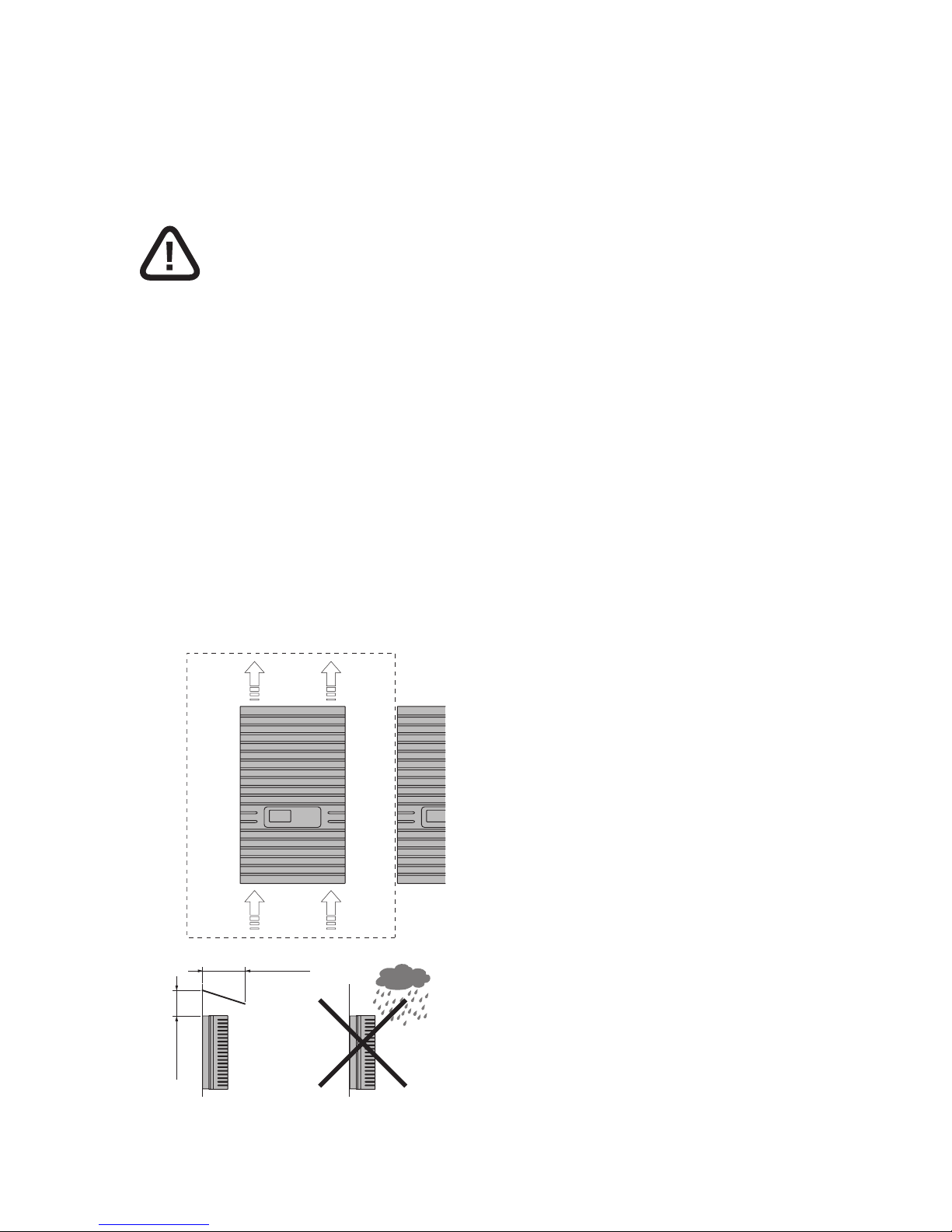
· The high protection type IP 54 allows installation indoors and in roof-covered areas outdoors,
however the Solar Inverter may not be directly
exposed to rain.
300 mm
300 mm
300 mm
300 mm
Wall
Ceiling
cold
air
hot
air
>300 mm
>350 mm
Mechanical load-bearing capacity
· Note during installation that the Solar Inverter
weighs 26 kg. The installation surface must be
firm and able to carry this weight in the long
term.
Thermal interaction
· The installation surface must consist of flameretardant material (not suitable: surface of wood
or plastic; suitable: concrete and masonry), as
the frame of the Solar Inverter can heat up to a
maximum of 70°C.
· A minimum distance of 300 mm to other devices,
cabinets, ceilings, cable ducts, etc. must be
maintained above, below and to the sides of the
housing. See the figure Requirements for installation location.
· The Solar Inverter must be installed vertically to
enable sufficiently free convection.
· Several Solar Inverters may not be mounted over
each other to prevent them from heating each
other.
· Ensure sufficient heat dissipation when installing
the Solar Inverter in a switch cabinet or closed
room.
· The ambient temperature may not drop below or
exceed -25°C and +45°C respectively. At ambient
temperatures above 45°C, the inverter automatically reduces its output.
· The Solar Inverter must not be exposed to direct
sunlight, to protect it from unnecessary external
warming.
Page 15
3 Installation
15
Installation
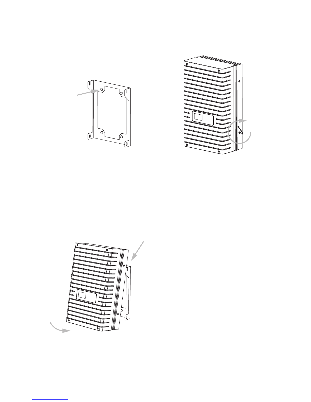
Proceed as follows to install the Solar Inverter:
1. Hold the wall bracket at the point at which you
want to attach the Solar Inverter and mark the
mounting holes.
2. Drill the holes with a 10 mm dia. drill bit. A drilling template with exact dimensioning can be
found in the appendix.
3. Install the wall bracket with corresponding
screws and dowels depending on the surface
condition.
4. Unscrew the locking screw of the Solar Inverter
at the lower left with an Allen key
5. Hook the Solar Inverter into the cut-outs of the
installation frame at the top on both sides.
6. Secure the Solar Inverter by tightening the locking screw.
Page 16
3 Installation
16
3.2 Electrical installation
Solar generator connection
Extreme danger from electric shock!
· Touching live parts can result in death.
· All electrical work must be conducted by a qualified electrician while observing the VDE regulations, national and other regulations!
· Execute the direct current wiring in accordance
with the system dimensioning of your planning
expert.
· Prepare all solar generator cables before you
carry out the connection of the solar generator
to the Solar Inverter.
· Check each solar generator string for proper
operation with an open-circuit voltage and
short-circuit current measurement.
· Check using the rating plate on the Solar Inverter
whether it is approved for the maximum solar
generator voltage.
· The positive and negative lines must be kept
electrically separate from the earth potential.
· Touchable, live parts of the solar generator (e.g.
metal frame, carrying structure, etc.) must be
earthed (connection with PE).
· Check the solar generator against short-circuits
to earth.
· Before connecting the solar generator to the
Solar Inverter, the integrated DC load break
switch must be opened quickly (position 0).
· After the PV solar generator is connected to
the Solar Inverter and the DC load break switch
is switched on, the direct generator voltage is
present internally.
· The connectors may not be separated while
under load.
· Always separate the grid connection first by
switching off the corresponding mains fuse and
then the solar generator side by quickly opening
the DC load break switch.
Survey
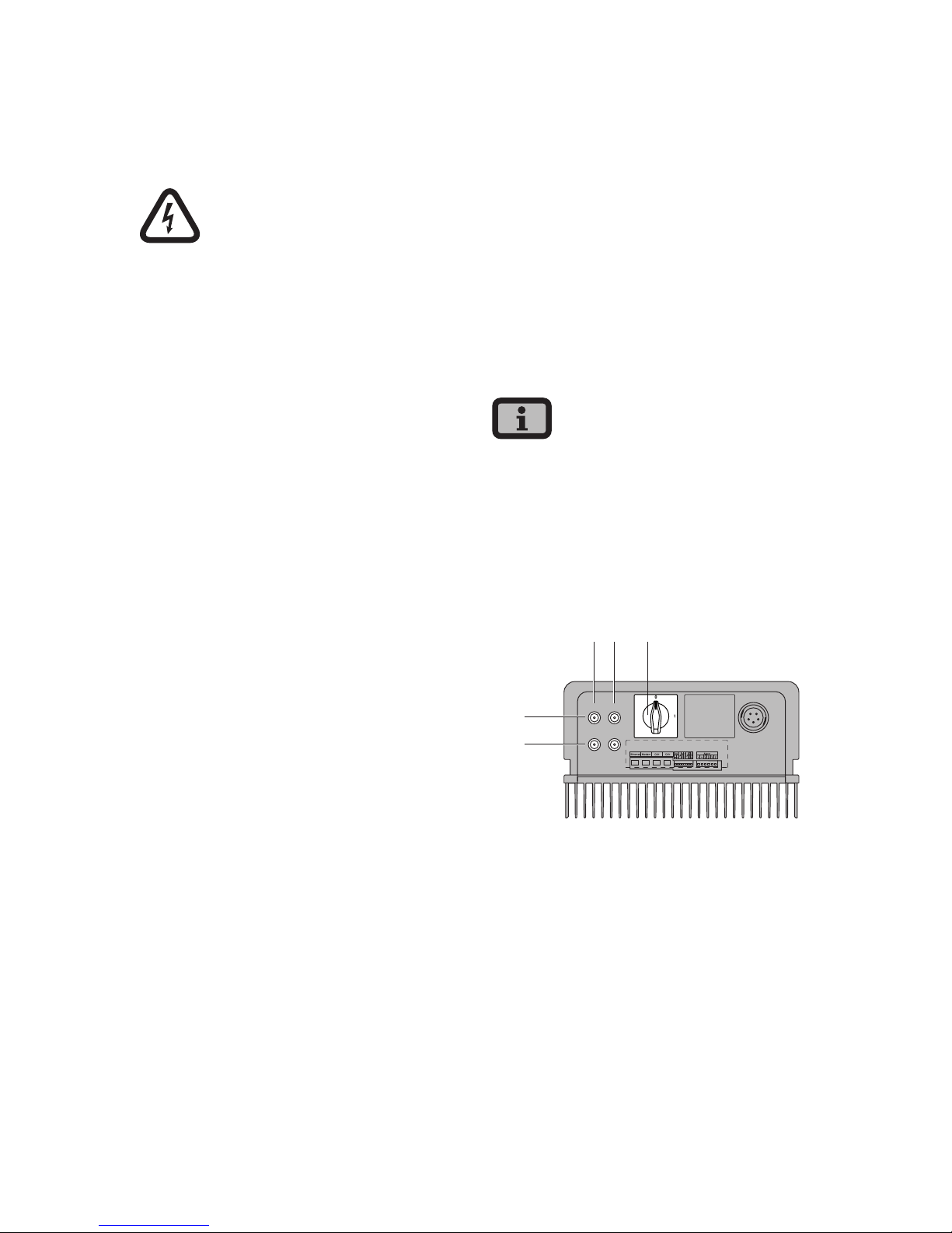
The solar generator can be directly connected to the
Solar Inverter with two strings. The connection is
made via the shockproof Tyco Solarlok plug-in connection system accessible from outside.
The Solar Inverter has two electrically connected
DC inputs, which are arranged in pairs on the
underside.
· The solar generator strings must be identically
dimensioned and comply with the specifications
of the Solar Inverter.
· No external DC load break switch is required. A
DC load break switch as required in accordance
with DIN VDE 0100-712 is integrated in the Solar
Inverter.
+–
+–
1
2
3– +
1 Connection of solar generator string 1
2 Connection of solar generator string 2
3 DC load break switch
Page 17
3 Installation
17
Tyco Solarlok plug-in connection system
The Solarlok plug-in connection system is used for
the simple, reliable connection of individual solar
generators up to the Solar Inverter.
Components
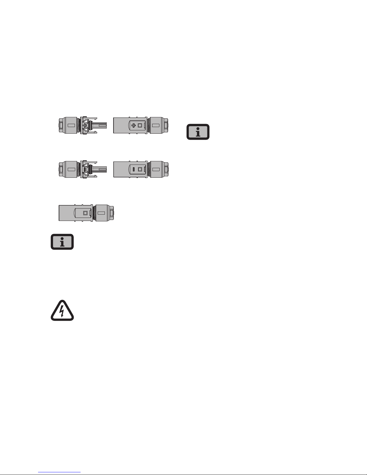
The following connectors are used:
· Positively coded connector
· Negatively coded connector
· Neutral connector
The neutral connector can be used to connect both
positively and negatively coded sockets.
Installation
Extreme danger from electric shock!
· Touching live parts can result in death.
· All electrical work must be conducted by a qualified electrician while observing the VDE regulations, national and other regulations!
· Tyco Solarlok connectors are only reliable for
connection on permanently installed lines.
· Only the Tyco-Solarlok hand crimping pliers may
be used to crimp the connectors.
· During preassembly, the connectors must be
separated from all other voltage sources.
· The connectors may not be separated while
under load. The circuit must be opened at a suitable point for this purpose.
· Provide the lines with corresponding stickers as
close as possible to the connectors to prevent
confusion.
· Any kind of soiling (dust, moisture, etc.) has a
negative effect on the connector system with
regard to function over the intended period of
use. This particularly applies to the suitability for
use of the seals and the crimping of the contacts. Therefore, extreme care must be taken to
achieve proper processing during assembly.
· Various circular contacts are used for different
conductor cross-sections with the Tyco Solarlok connectors. The correct tool insert must be
used in accordance with this cross-section. The
included Tyco Solarlok connectors are equipped
with circular contacts for a cable cross-section of
4 mm² to 6 mm².
· The seals and clamping baskets used in the
preassembled connectors are approved for cable
sheath diameters from 4.5 mm to 6.9 mm. Special
seals and clamping baskets must be used for
cables with a sheath diameter greater than
6.9 mm.
· The Tyco Solarlok hand crimping pliers can be
purchased from your sales partner.
Page 18
3 Installation
18
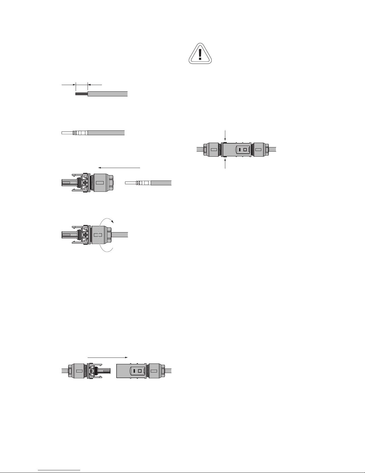
The following sequence must be observed during
assembly:
1. Stripping the voltage-free line.
8
2. Crimping on the circular contact with the Tyco
Solarlok hand crimping pliers.
3. Sliding the cable gland onto the line and engaging the contact in the connector housing.
4. Tightening the cable gland with 1.5 Nm.
Handling
The positively/negatively coded connectors are
marked with polarity symbols and a coloured ring
(blue = negative, red = positive). They are equipped
with coding ribs for assignment, which ensures that
only connectors of the same polarity can be connected to each other.
Connecting socket and plug. The system is only correctly locked if the locking hooks are recessed flush
in the mating piece.
CAUTION
The connectors may not be separated while under
load. The circuit must be opened at a suitable point
for this purpose.
Release the locking device by pressing on the ribbing of the locking hooks and pulling them apart.
Page 19
3 Installation
19
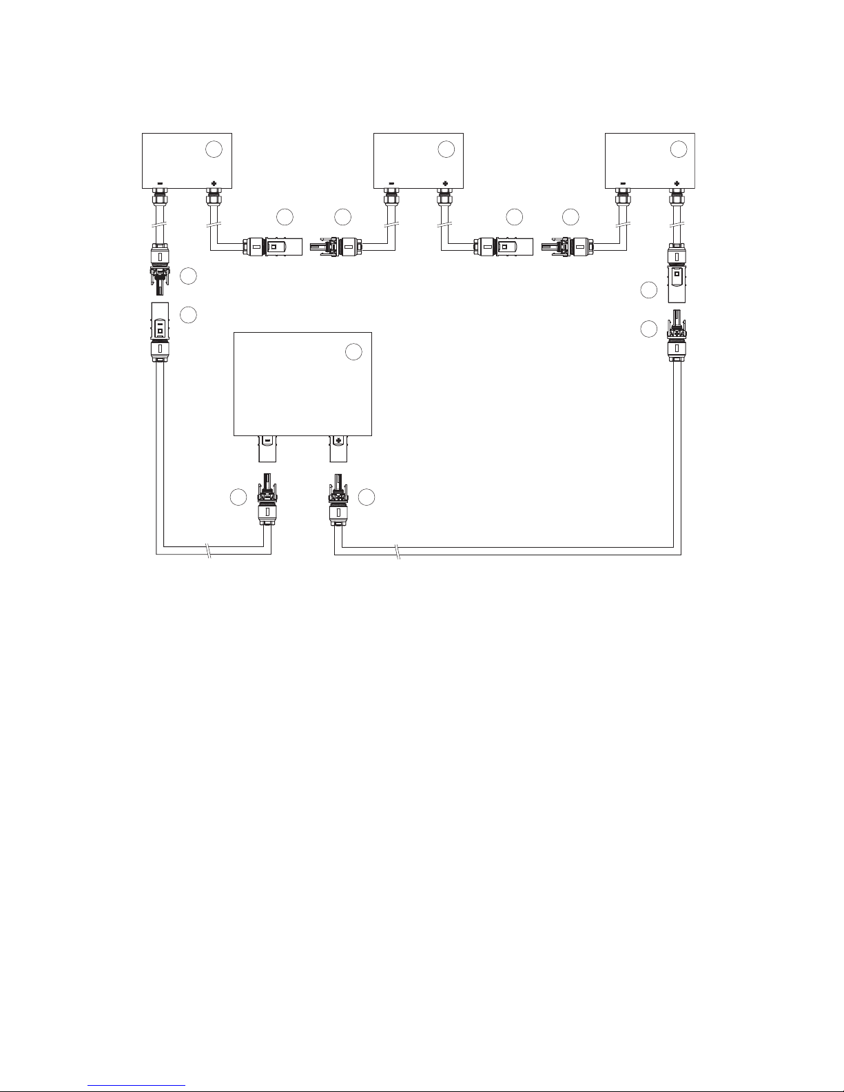
Connection example
2
3
5
4
5 2 5 2
2 4
1 1 1
6
– –NN
N
+
–
–
+–
1 Solar module box
2 Negatively coded socket
3 Negatively coded plug
4 Positively coded socket
5 Neutral connector
6 Solar inverter
Page 20
3 Installation
20
Grid connection
Extreme danger from electric shock!
· Touching live parts can result in death.
· All electrical work must be conducted by a qualified electrician while observing the VDE regulations, national and other regulations!
· Observe the pin assignment of the AC bayonet
connector. An incorrect assignment can result in
the device being destroyed.
· No consumers may be connected to the supply
line from the Solar Inverter to the mains fuse.
· Always separate the grid connection first by
switching off the corresponding mains fuse and
then the solar generator side by quickly opening
the DC load break switch.
If the voltage on the AC connection exceeds the
permissible value due to a long line length or an
insufficient cable cross-section, the Solar Inverter
will disconnected from the grid. In power grids with
a low output and a high solar generator output, this
can lead to individual Solar Inverters being switched
off and then on again several times.
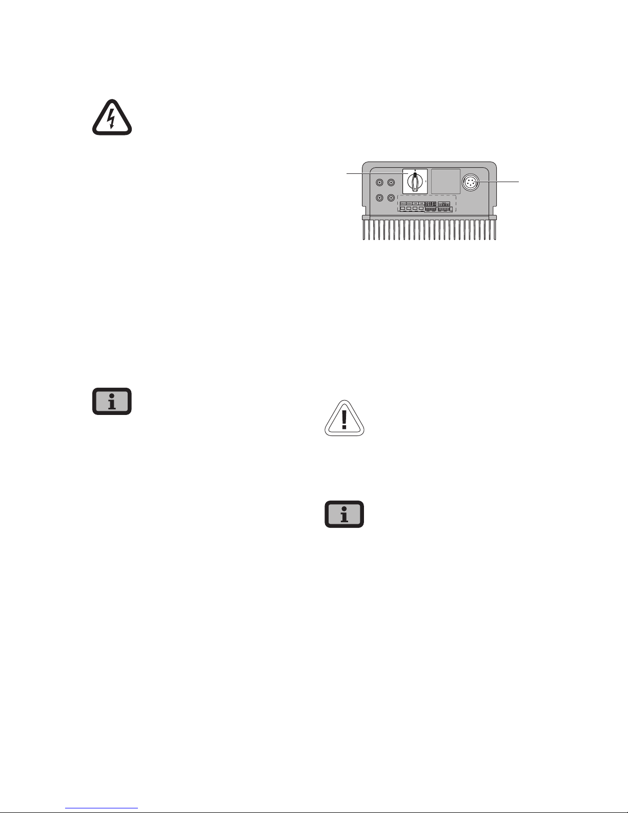
Survey
An AC bayonet connector on the underside of the
unit is used for the three-wire grid connection (L, N,
PE) of the Solar Inverter. The grid connection should
always be 1-phase. Feeding is single-phase via AC
terminal 2.
+–
+–
1
2
1 DC load break switch
2 AC connection
A basic distinction is made between two different
connection options of the Solar Inverter to the public power grid:
· 3-phase AC grid (e.g. Germany)
· 1-phase AC grid (e.g. Italy, Spain)
CAUTION
· Observe the regional regulations for the grid
connection.
The Solar Inverter always only feeds via AC terminal
2. If several Solar Inverters are operated in parallel
in a 3-phase grid, AC terminal 2 of the device must
be distributed uniformly among the grid phases L1,
L2 and L3 to avoid unequal loading.
Page 21
3 Installation
21
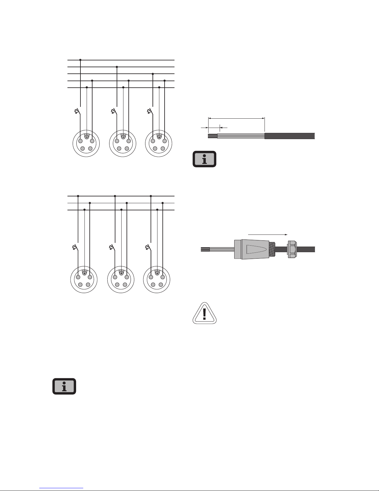
3-phase grid connection (3-phase AC connection)
Inverter 1 Inverter 2 Inverter 3
PE
N
L3
L2
L1
1
2
4
3
1
2
4
3
1
2
4
3
1-phase grid connection (AC connection)
Inverter 1 Inverter 2 Inverter 3
PE
N
L1
1
2
4
3
1
2
4
3
1
2
4
3
A corresponding circuit breaker is recommended as
a line protection element in the grid feed direction:
NT 2500: 16 A
NT 3700: 25 A
NT 4200: 32 A
NT 5000: 32 A
with slow-blow characteristic B
· Depending on the grid operator and the feed
point, a three-phase meter or a single-phase
meter must be used.
· Some grid operators require the use of a reversecurrent-capable meter.
AC bayonet connector
The AC bayonet connector is permissible for cable
sheath diameters from 13 mm to 20 mm.
The following sequence must be observed during
assembly:
1. Strip the voltage-free line and the cable ends.
10
52,5 (PE 55)
For lines with a cable sheath diameter from 16 to 20
mm, the cable gland must be adapted accordingly.
To do this, cut out the inner section of the blue sealing ring.
2. Slid the cable gland and the plug housing onto
the line.
3. Connect the cable ends to the plug terminals in
accordance with the pin assignment.
Tightening torque: 0.7 Nm.
CAUTION
Incorrect pin assignment may result in destruction of
the unit!
Page 22
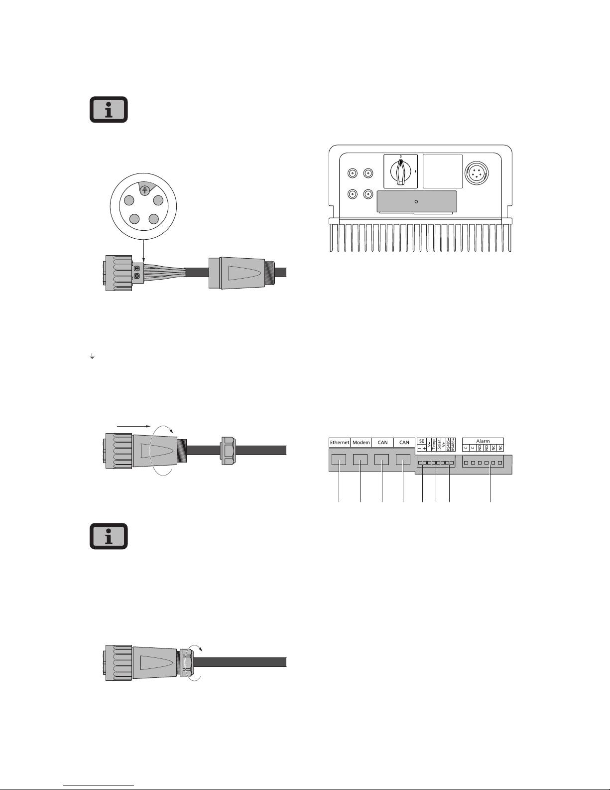
3 Installation
22
Pin assignment for AC bayonet connector
The diagram shows the connections inside the AC
connector, as indicated by the cut-out at the PE
connection.
1
2
4
3
1 = N
2 = L (feed-in phase)
3 = not used
4 = not used
= PE (protective earth conductor)
4. Screw plug housing to plug. To do this, press the
outer ring of the plug toward the plug housing.
Tightening torque: 1-2 Nm.
5. Tighten the cable gland.
Make sure the line is provided with a strain relief
device. When using cables with a diameter < 16 mm,
the line must be relieved just behind the connector.
Tightening torque for cable sheath diameters
from 13 to 20 mm = 6 to 8 Nm
3.3 Installing communication
The interfaces are located behind the weatherproof connection box on the underside of the Solar
Inverter.
+–
+–
1
2
To open the connection box, loose the centre screw.
Then carefully pull way the box toward the front.
After you have installed the connection cable, close
the box again by guiding the locking hooks into the
notches in the housing and then pressing the box
onto the housing.
Retighten the mounting screw.
Interface overview
2
1 3 4 8765
1 Ethernet connection
2 Modem connection
3 CAN IN
4 CAN OUT
5 S0 interface (pulse output, e.g. for large display)
6 Connection for temperature and irradiation
sensor
7 RS485 interface
8 Connection for alarm relay
Page 23
3 Installation
23
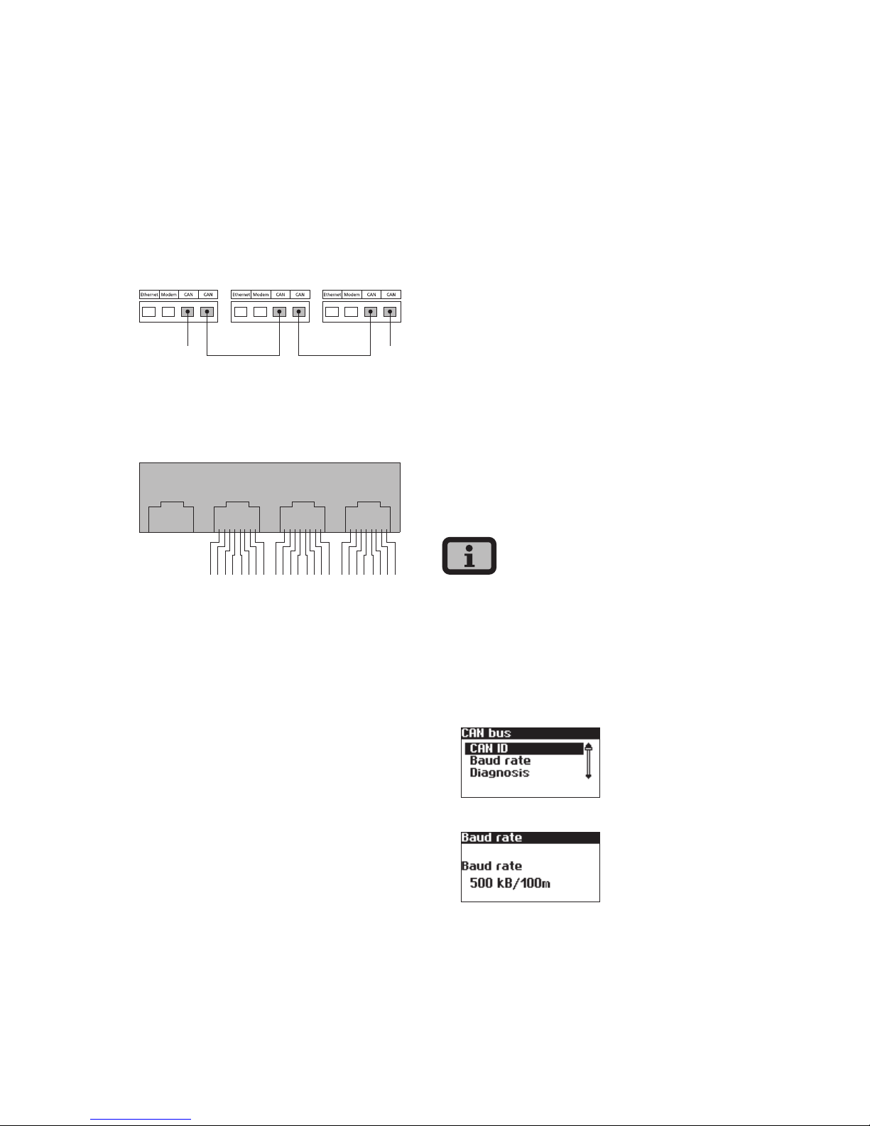
Networking Solar Inverters via CAN bus
Solar Inverters from the NT, AT und PT series can
be networked via the CAN bus interface. Use the
included Ethernet cable to network the Solar Inverters with each other. Connect a terminating resistor
at the first and last Solar Inverter in the series. The
pluggable terminating resistors are included in the
delivery.
Device 1 Device 2 ...
1 1
1 Terminating resistor
Pin assignment
Ethernet Modem CAN CAN
2
1346578
2
1346578
2
1346578
The connectors for the CAN interfaces CAN IN and
CAN OUT and for the modem interface have the
following pin assignment
CAN
Pin ID Meaning
1 N.C.
2 CAN_GND 0 V / GND
3 CAN_H bus line (dominant high)
4 CAN_L_T termination
5 CAN_H_T termination
6 CANL bus line (dominant low)
7 CAN_SHLD optional CAN Shield
8 N.C.
Modem
Pin ID Meaning
1 >1 TXh
2 >2 TX1
3 <3 RXh
4 -4 VCC
5 -5 GND
6 <6 RXI
7 <7 R1h
8 <8 R1I
The total length of the CAN bus depends on the
selected bit rate. The following table shows the possible bit rates and the resulting bus lengths.
Bit rate Bus length
100 kbit/s 650 m
125 kbit/s 500 m
250 kbit/s 250 m
500 kbit/s 100 m
Solar Inverters of the PT series are delivered with a
default setting of 125 kbit/s. The default setting for
Solar Inverters of the NT and AT series is 500 kbit/s.
When Solar Inverters from different series are networked the bit rate in all units must be identical.
The rate can be set via the Solar Inverter display or
the Sunways Browser.
Setting the bit rate via the display menu:
«Settings – Network – CAN Bus – Baud rate»
Page 24
3 Installation
24
Up to 99 NT, PT and AT series units can be networked via a CAN bus. The following table shows
the recommended cable cross-sections depending on
the bus length and the number of nodes:
Bus length / Number of nodes 32 64 100
100 m 0,25 mm
2
or AWG 24 0,25 mm2 or AWG 24 0,25 mm2 or AWG 24
250 m 0,34 mm
2
or AWG 22 0,5 mm2 or AWG 20 0,5 mm2 or AWG 20
500 m 0,75 mm
2
or AWG 18 0,75 mm2 or AWG 18 1,0 mm2 or AWG 16
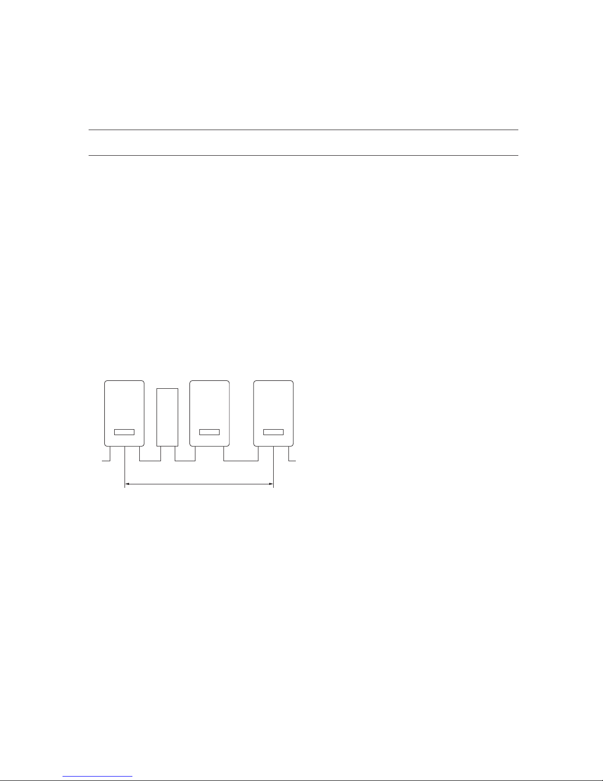
In cases where the values specified in the table cannot be adhered to, a CAN bridge for boosting the
signal must be installed, through which the length
of the CAN bus can be extended by up to 500 m.
The requirement to install a CAN bridge is therefore
determined by the bus length, the number of nodes
and the cable cross-sections.
CAN-Bus
Network length / number of nodes /
cable cross-section outside the table
values – 1 or several CAN bridge(s)
INVERTER
INVERTER
INVERTER
CAN-BRIDGE
The CAN bridge is available from Sunways. For
further information please contact the Technical
Hotline.
The CAN bridge subdivides the bus into two physically independent segments. The maximum cable
length of each segment is determined by the set bit
rate. With a bit rate of 125 kbit/s two segments with
a maximum length of 500 m each are possible. The
total line length can therefore be up to 1 km under
ideal conditions.
Page 25
3 Installation
25
In systems with Solar Inverters from the PT series
the CAN bridge can be integrated directly in the PT
Solar Inverter and supplied via the 24 V DC power
supply unit of the inverter. In systems with AT Solar
Inverters and units from the new NT series (900 V)
the CAN bridge can be integrated in the AC distribution. In this case an external 24 V DC supply is
required (power consumption 1.5 W).
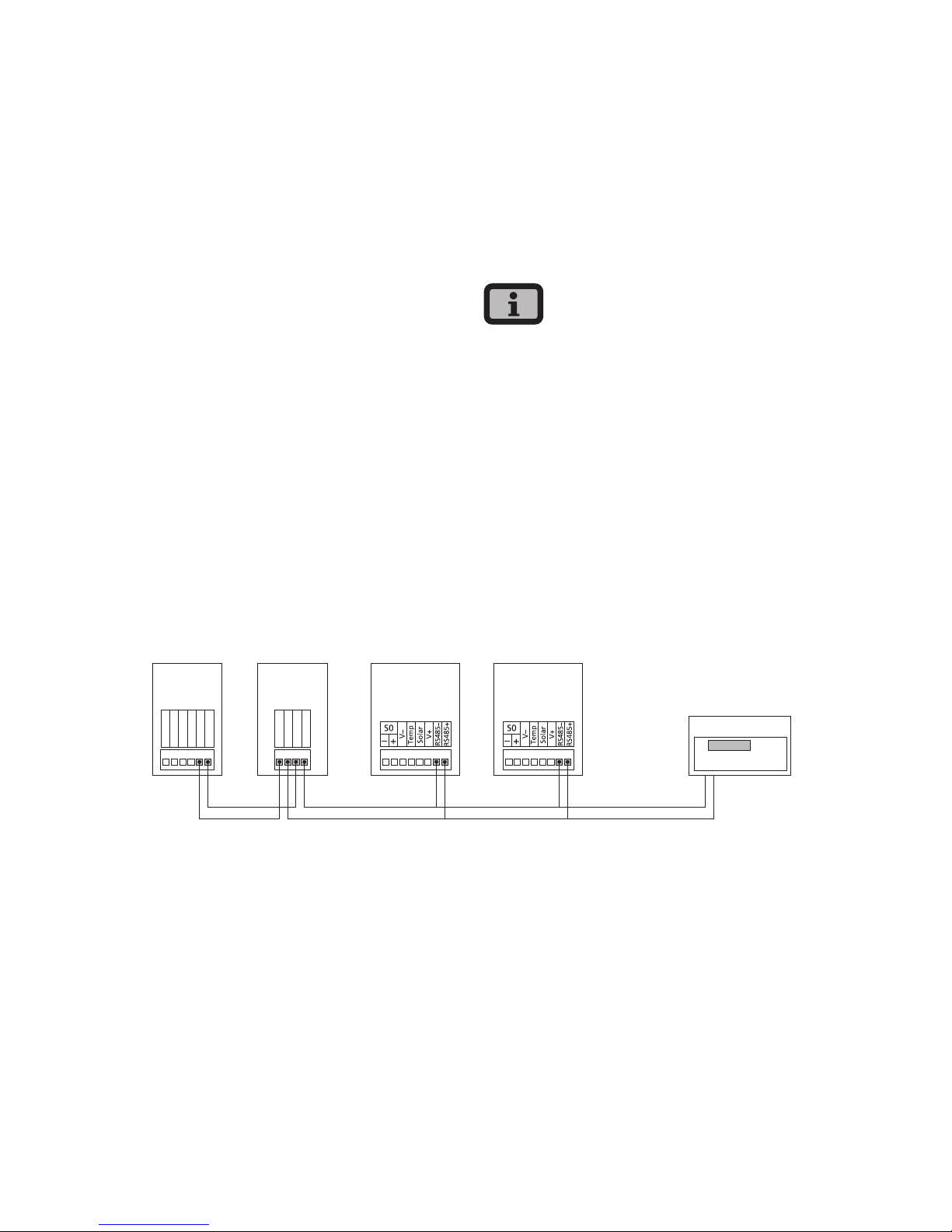
Networking Solar Inverters via RS485 interface
For joint monitoring of a solar system with Sunways
Solar Inverters from the older NT generation (750 V
or 850 V) you can use the RS485 interface integrated
in the Solar Inverters. The system networked with
the RS485 interface can be monitored with the Sunways Communicator.
· Use a twisted two-wire cable to network the
Solar Inverters with each other.
· Mount the terminating resistor on the last Solar
Inverter.
NT 8000/10000: Jumper RS485MATCH
NT 2600...NT 6000: Jumper JP400
Networking via RS485 interface
RS485GND
RS485+
RS485–
RS485GND
RS485+
RS485–
RS485+
RS485–
RS485+
RS485–
NT 8000
NT 10000
NT 2600...
NT 6000
NT (900 V)
or AT
NT (900 V)
or AT
Sunways
Communicator
Page 26

3 Installation
26
S0 interface
The S0 pulse output enables, for example, the connection of a large display (Sunways Display) for
displaying the momentary output, the energy yields
and the CO
2
reduction.
You can use the S0 interface on the master if you
want to transmit the entire line yields as a sum to a
large display.
The S0 interface is adjusted via the display on the
inverter. Go to the menu «Settings – Network
– Interfaces».
· Please note that the maximum pulse rate may
not be greater than 15 pulse/sec. Calculate the
pulse rate depending on the size of the solar
system using the following formula:
Pulse rate [pulses/kWh] =
50,000/system size [kWp]
· The pulse rate must be set on your Solar Inverter
and on the large display.
Connection of temperature and irradiation sensor
The optional addition of an irradiation sensor
(model Si-01TC-K from Ingenieurbüro Mencke &
Tegtmeyer) with an integrated PT-100 temperature
sensor for temperature measurement enables the
acquisition of irradiation data and the corresponding module temperature and storage in the internal
data memory as a 5-minute mean value. This additional measuring device helps analyse the system
output. Based on the values, any errors on the PV
generator, e.g. shading or failure of solar cells, can
be detected.
The sensor is activated via the display. In the menu
«Settings – Network – Interfaces» you can select the
sensor type in the «Irrad.» and «Temp.» field.
Page 27
3 Installation
27
Assignment of sensor connection
Sensor
connector pin
assignment
Sensor
connection
designation
Solar Inverter
connection
Pin 1 Plus signal
temperature
Temp
Pin 2 Plus signal
irradiance
Solar
Pin 3 Reference earth V-
Pin 4 Plus connection for
supply +5V
V+
Connecting alarm relay
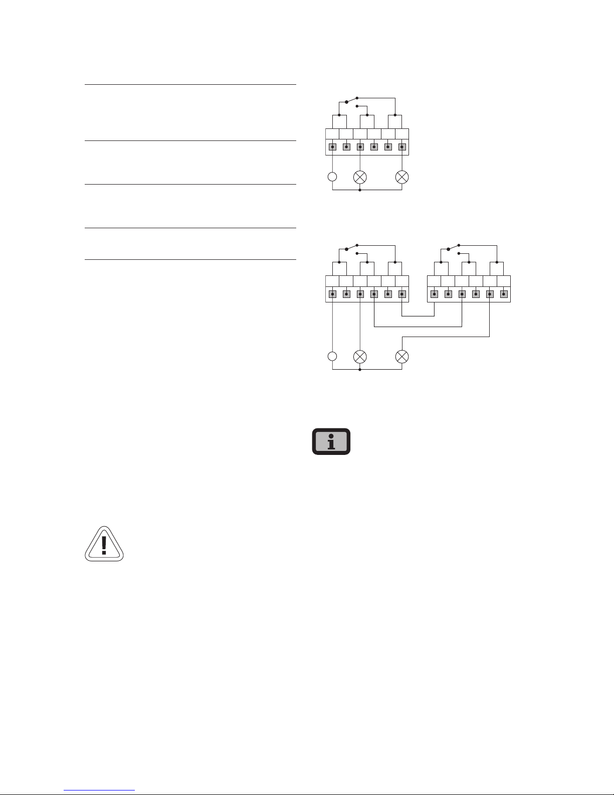
The Solar Inverters are equipped with a potentialfree alarm relay as standard. The relay can be
designed as a make-contact element or as a breakcontact element and is actuated for all malfunctions
signalled by the device. This ensures a faster, more
reliable indication of a possible fault in the PV system on site. For PV systems with several Solar Inverters, the individual relays can be switched in parallel
and connected via a common indicator lamp.
The master also signals faults from other devices in
the CAN network via the alarm relay. It is therefore
sufficient for simple alerting to connect the alarm
relay of the master.
CAUTION
The alarm relay is designed for 230 V/2 A. Higher
outputs/voltages can result in the relay being
destroyed. The connected signalling device must
be fused separately. The terminals are intended for
a cable cross-section of 0.2 mm
2
to 1.5 mm2. When
dimensioning the cross-section, also take the current
consumption of the connected signalling device into
account.
Wiring diagram for a single device
~
1 2
NO
NO
NC
NC
C
C
Wiring diagram for several devices
~
1 2
NO
NO
NC
NC
C
C
NO
NO
NC
NC
C
C
1 Indicator lamp, red
2 Indicator lamp, green
The Solar Inverter is supplied by the feed-in phase
from the AC grid. If the feed-in phase fails the alarm
relay cannot switch, even in the event of a fault.
Page 28
28
4 Commissioning
4.1 Connecting and disconnecting Solar Inverter
CAUTION
· Ensure proper mechanical and electrical installation before commissioning the Solar Inverter.
· Check the proper condition of the electrical lines.
· Always separate the grid connection first by
switching off the corresponding mains fuse and
then the solar generator side by quickly opening
the DC load break switch.
· The Tyco Solarlok connectors of the solar generator connection may not be disconnected while
under load. The DC load break switch must be
quickly switched to the switching position 0.
The Solar Inverter is supplied from the grid. The
Solar Inverter switches on automatically when sufficient solar generator output is available. Corresponding switch-on and switch-off thresholds have
been defined for this purpose.
Connecting
1. Switch on the grid connection with the external
circuit breakers.
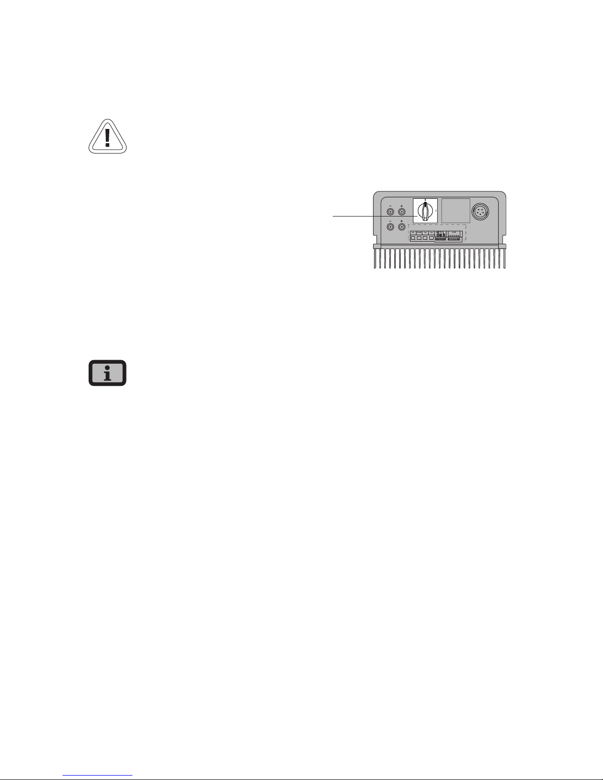
2. Switch on the solar generator voltage by quickly
closing the DC load break switch (switching position 1). The Solar Inverter takes up operation
when sufficient input voltage is available.
1
1 DC load break switch
The operating LED lights up in accor-dance with the
operating state.
The commissioning menu opens when the Solar
Inverter is connected for the first time.
Switching off
1. Open the grid connection by switching off the
circuit breaker.
2. Disconnect the solar generator side by quickly
opening the DC load break switch (switching
position 0)
Page 29
4 Commissioning
29
4.2 Commissioning
The commissioning menu is automatically opened
the first time the Solar Inverter is connected. It helps
you make the standard settings.
For a better understanding of keyboard operation,
please also see the chapter Operation.
The commissioning of the Solar Inverter as
· a single device
· a master and slaves with several networked
devices
is described in detail in the following.
Please note:
Once the system has been commissioned, the
country can no longer be changed via the menu. To
change the country retrospectively, please contact
the technical hotline on Tel +49 (0)7531 996 77-577.
Commissioning single device
System with one Solar Inverter
Single device
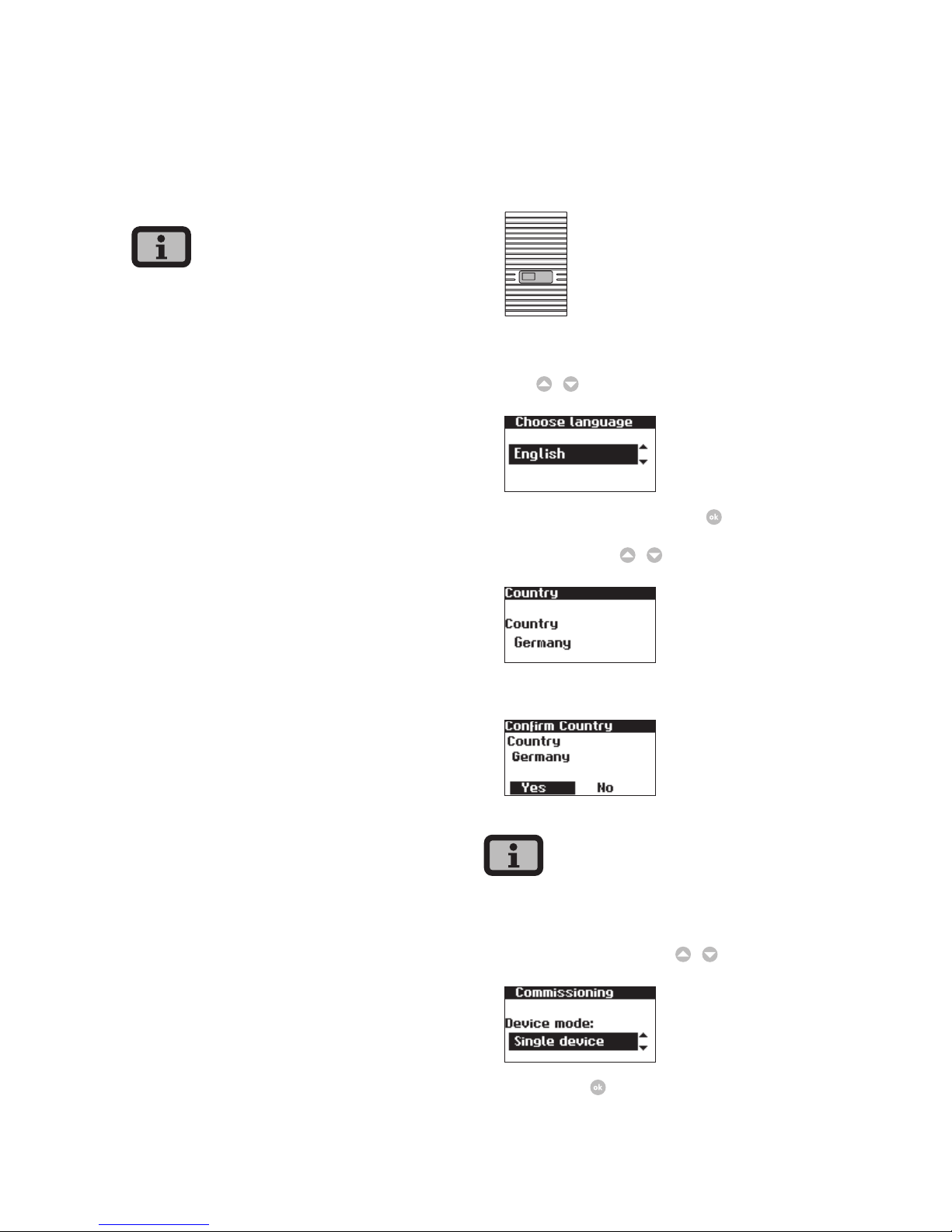
1. The commissioning process starts with setting of
the display language. Select required language
with
/
.
Confirm selected language with .
2. Select the country
/
.
Confirm the country of installation.
Your Solar Inverter will only start feeding electricity
once the country of installation has been confirmed.
3. Select «Single device» with
/
.
Confirm with .
Page 30
4 Commissioning
30
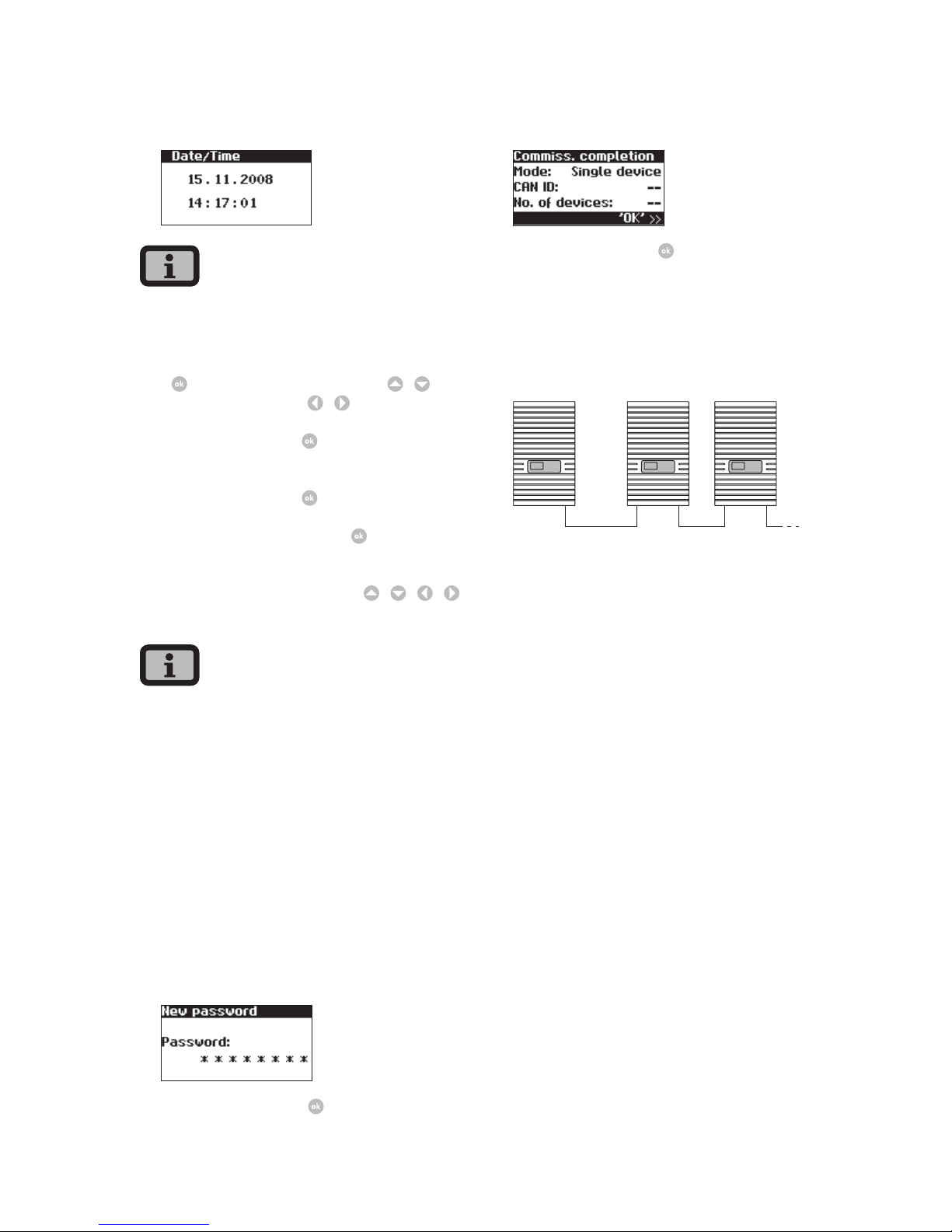
4. Set date and time.
Please proceed with caution for time settings, as
they directly affect data logging. For example, if you
set the time back by 1 hour, then the existing data
for the last hour will be overwritten. Select date
with
. Change selected number with / and
jump to next number with
/
.
Save the set date with
then set the time
accordingly.
Save the set time with
5. Set password. Select password
Default password is:
* * * * * * * *
A new password can be set with
/ / /
as an option.
Please note:
Numerals from 0 – 9 and letters from a – z and from
A – Z are admissible.
The password always has 8 characters. If the password you choose is fewer than 8 characters in
length, the remainder, up to the full 8 characters, is
filled with “*” symbols.
For example:
You choose “Solar” as your password. This password
has 5 characters. The system therefore then automatically adds three “*” symbols, meaning that your
password becomes “Solar***”.
Confirm password with .
6. Completion of commissioning
Confirm overview with .
Commissioning several networked devices
System with several Solar Inverters
master slaves (secondary units)
Before commissioning, all devices must be interconnected via the CAN bus interface. See section
Networking Solar Inverters via CAN bus.
Switch on all devices following installation. Commissioning begins with the master you have selected.
Page 31
4 Commissioning
31
Compatibility between Sunways Solar Inverters
The following table provides an overview of which
devices can be networked with each other and how,
and lists any special considerations:
NT Series (900 V) PT series AT series NT series (850 V)
NT series
(850 V)
with RS485:
· Sunways Portal:
with Sunways
Communicator
NT with RS485 / PT
with CAN bus:
· Sunways Portal:
connect NTs with
Sunways Communicator, PTs with
Sunways Modem
or DSL/network to
the Internet
· Sunways Browser:
only available for
PT
with RS485:
· Sunways Portal:
with Sunways
Communicator
· Sunways Monitor
with RS485:
· Sunways Portal:
with Sunways
Communicator
· Sunways Monitor: with interface
converter
AT series with separate CAN
networks:
· Sunways Browser
· Sunways Portal:
NT devices (900
V) must be operated in a separate
CAN network
with independent
main unit
with CAN bus:
· Sunways Browser
· Sunways Portal
· The PT Solar
Inverter must
be the main
unit.
with CAN bus:
· Sunways Browser
· Sunways Portal
PT series with separate CAN
networks:
· Sunways Browser
· Sunways Portal:
NT devices
(900 V) must be
operated in a
separate CAN
network with
independent
main unit
with CAN bus:
· Sunways Browser
· Sunways Portal
NT Series
(900 V)
with CAN-Bus
(CANopen/CiA437):
· Sunways Browser
· Sunways Portal
Page 32
4 Commissioning
32
Commissioning the master
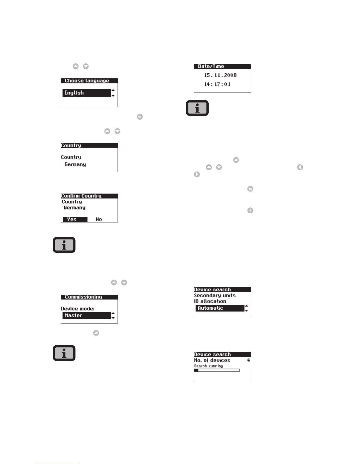
1. The commissioning process starts with setting of
the display language. Select required language
with
/
.
Confirm selected language with .
2. Select the country
/
.
Confirm the country of installation.
Your Solar Inverter will only start feeding electricity
once the country of installation has been confirmed.
3. Select «Master» with
/
.
Confirm with
.
The other devices in the CAN network are automatically configured as slaves.
4. Set the data and time centrally for all connected
devices.
Please proceed with caution for time settings, as
they directly affect data logging. For example, if you
set the time back by 1 hour, then the existing data
for the last hour will be overwritten.
Select date with
. Change selected number
with
/
and jump to next number with /
.
Save the set date with
then set the time
accordingly.
Save the set time with
.
5. Start the device search from the main unit.
The IDs for the secondary units can be allocated
automatically or manually. When manual ID
allocation is selected the ID must be requested at
the secondary unit. With automatic ID allocation
this step is not required, since the device IDs are
assigned automatically.
The following display appears during the device
search:
Page 33
4 Commissioning
33
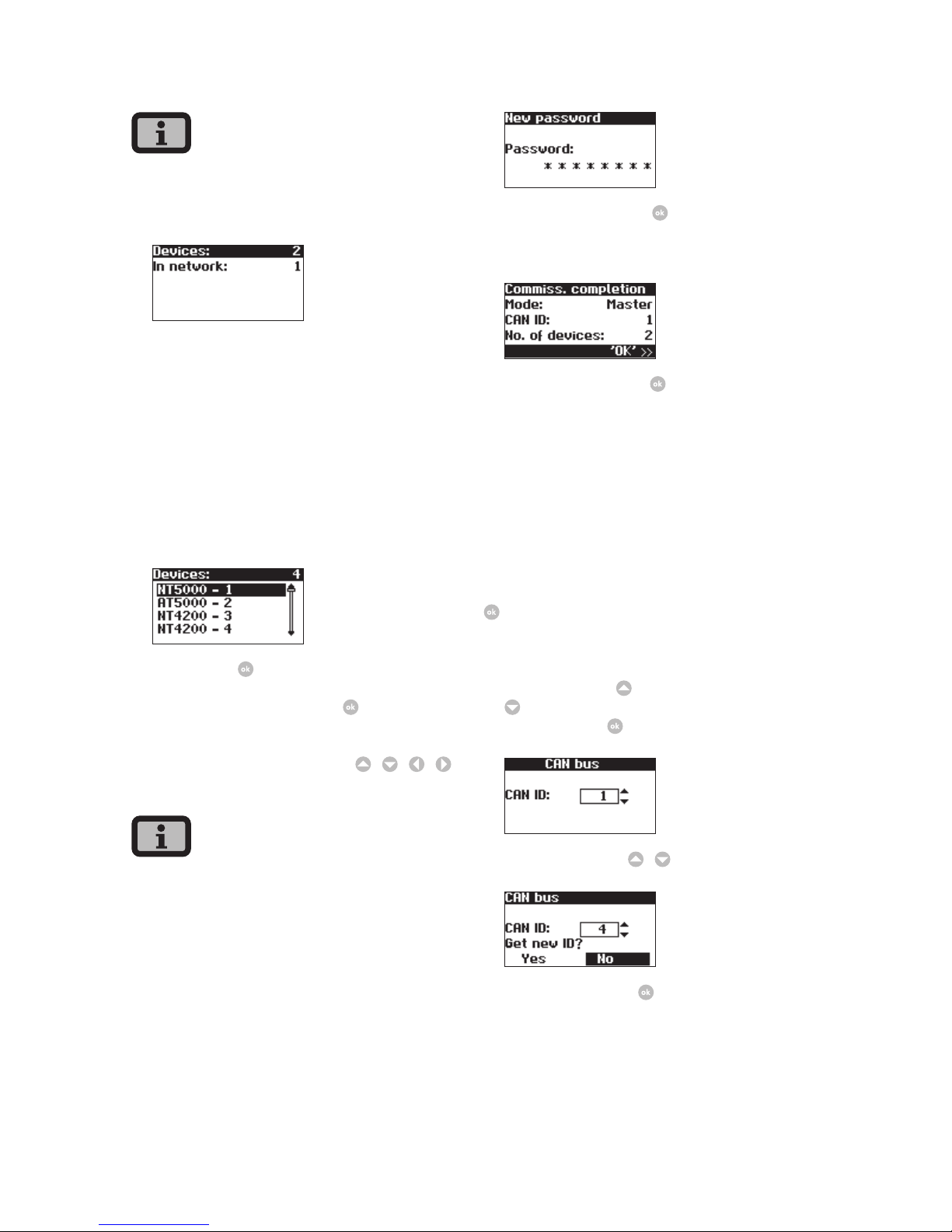
Depending on the size of the network, it may take
a moment until the master has found all slaves and
added them to the list.
Devices = total number of devices found in CAN
network, including master
In network = number of configured devices,
including master
After the master has found all connected slaves,
these must be configured before commissioning of the master is continued. The device list
is updated and extended whenever a slave is
configured.
Confirm with .
6. Set password. Select password
Default password is:
* * * * * * * *
A new password can be set with
/ / /
as an option.
Please note:
Numerals from 0 – 9 and letters from a – z and from
A – Z are admissible.
The password always has 8 characters. If the password you choose is fewer than 8 characters in
length, the remainder, up to the full 8 characters, is
filled with “*” symbols.
For example:
You choose “Solar” as your password. This password
has 5 characters. The system therefore then automatically adds three “*” symbols, meaning that your
password becomes “Solar***”.
Confirm password with .
7. Completion of commissioning
Confirm overview with .
Commissioning slaves
The procedure for commissioning secondary units
depends on the type of device search. Once a main
unit has been defined and manual ID allocation
was selected (e.g. for systems with AT and PT), each
secondary unit automatically displays a CAN ID
request. If automatic ID allocation was selected on
the main unit, this step is skipped. In this case completion of commissioning must be confirmed with
at each secondary unit.
1. For manual device search only:
Request CAN ID. Request next highest free ID
from master with
or next lowest free ID with
. The master assigns a free ID to the slave. Con-
firm the ID with
within 5 seconds.
Request further IDs
/
.
Confirm CAN ID with
within 5 seconds.
Page 34
4 Commissioning
34
· The data for the individual slaves can be assigned
in the Sunways Browser and in the menu of the
master based on the IDs.
· The CAN-ID 1 is automatically assigned to the
master. This means the slaves can be assigned IDs
between 2 - 99.
· Commissioning cannot continue until an ID has
been requested from the master.
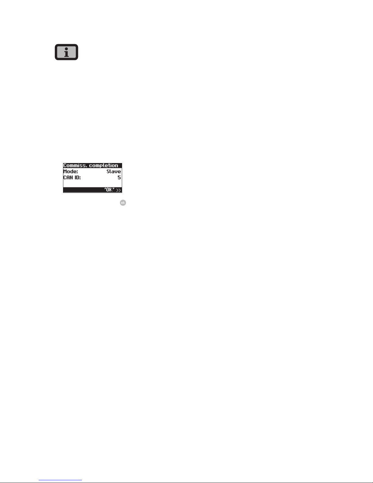
2. Completion of commissioning
Confirm overview with .
3. Carry out commissioning for all other slaves as
described above.
Later commissioning
If you add new devices or replace existing ones in
your solar system, then you can display the device
list in the display on the master under «Settings –
Network – CAN bus». The new device can then be
put into operation in accordance with the description for commissioning slaves.
Page 35
35
5 Operation
5.1 Operating elements
Operating field
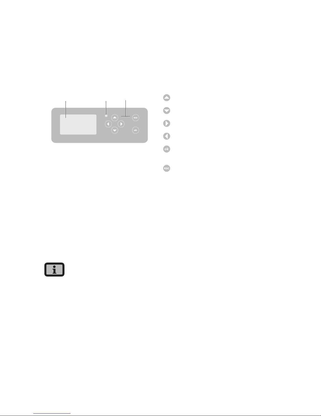
The Solar Inverter is operated via the operating field
on the front.
1 2 3
Solar Inverter NT 5000
1 LCD display (lighted)
2 Operating LED
3 Keyboard
LCD display
A graphics-capable, monochrome dot matrix display
is integrated in the operating field. In standard
operation the momentary output, daily yield and
status are displayed. The bar graph shows the
energy feed-in of the current day.
Press any key to activate the display lighting. If no
key is pressed for approx. 1 minute, the display
lighting goes out.
Important!
The LCD display is not a calibrated measuring device.
It is characterised by a slight, system-dependent
difference of a few percent. Exact accounting of
the data with the power supply company requires a
calibrated meter.
Keyboard
The keyboard can be used to navigate in the menu,
edit text fields, select entries from lists and enter
numbers consecutively and digit by digit. User
entries can only be made if the value to be changed
is selected. The cursor changes visibly in the editing
mode and indicates the digit to be changed.
-key Scroll up.
- key Scroll down.
- key Select menu item.
- key Back one menu level.
-key Select menu item and confirm your
entries.
-key Cancel.
Operating LED
The combined red/green LED indicates the device
status of the Solar Inverter:
· LED off
Solar Inverter is not active (night mode)
· LED green, continuously lit
Solar Inverter is active and feeds into power grid
(MPP mode)
· LED green, flashing
Solar Inverter is active and feeds into power grid,
however with current, output or temperature
limitation.
· LED red, continuously lit
an error has occurred (malfunction)
· LED red, flashing
a warning has been issued
Page 36
5 Operation
36
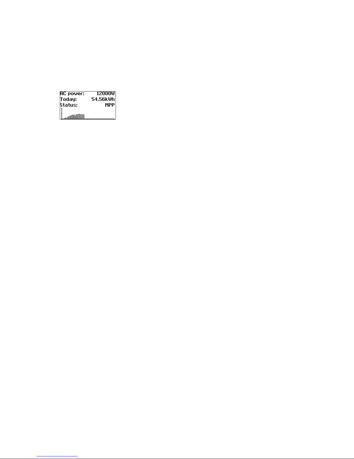
Standard screen (single device)
The standard screen is always shown when no
keyboard entry is made for more than 1 minute. It
can also be called up manually with the menu item
«Solar Inverter – Instantaneous Values».
The standard screen shows the main data at a
glance. The first line shows the current feed-in
power. The second line shows the energy fed in during the current day.
The status line indicates the device status with the
following messages:
MPP Feeding in MPP mode
AC cur.lim. Feeding with AC current limitation
DC cur.lim. Feeding with DC current limitation
Temp.lim. Feeding with temperature limitation
Output lim. Feeding with output limitation
Feed. Feeding
Warning A warning is active
Error An error has occurred
Night Night mode
Start Device initialisation phase
Com Upd. The communication software is being
updated
Cnt. Upd. The control software is being updated
Mon. Upd. The monitoring software being
updated
Wif Upd. The web interface is being updated
DWifUpd. The dynamic web interface is being
updated
MenSUpd. The menu structure is being updated
MenEUpd. The menu error texts are being
updated
WifSUpd. The web interface status texts are
being updated
RWP.Upd. The read/write parameters are being
updated
ROP.Upd. The read only parameters are being
updated
ParaUpd. The parameters are being updated
Min Upd. The minute values in the data logger
files are being updated
Day Upd. The daily values in the data logger files
are being updated
Mon Upd. The monthly values in the data logger
files are being updated
YearUpd. The annual values in the data logger
files are being updated
SMinUpd. The minute values in the system data
logger files are being updated
SDayUpd. The daily values in the system data log-
ger files are being updated
SMONUpd. The monthly values in the system data
logger files are being updated
SYrUpd. The annual values in the system data
logger files are being updated
The graphic in the lower section of the screen shows
the output curve for the current day as a bar graph.
The current period is shown as a flashing bar, as it is
still increasing.
Page 37
5 Operation
37
Standard screen (system)
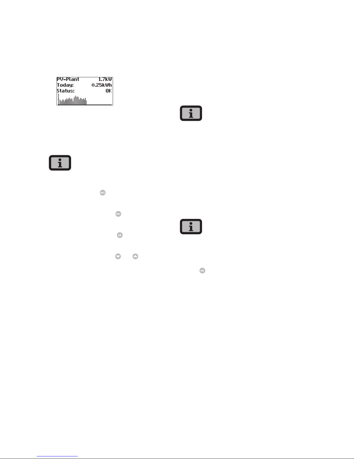
This screen shows the system data for a CAN-networked system.
Next to the total current system output, you also
see the energy yield of your solar system and any
status messages of all connected devices. These are
provided with the inverter number. «M» means that
the error has occurred in the master.
· The various functions are accessed via the menu.
The main menu is opened from the standard
screen by pressing
twice.
· You can always return to the standard screen by
pressing and holding the
key.
· If a status message is shown, then you can open
the error list directly with
.
· You can access other instantaneous values from
the standard screen with
and
.
5.2 Access rights
Operation of the Solar Inverter is divided into various areas protected with passwords.
The password has 8 digits or characters.
The password can be entered in the menu item «Settings – Login».
After a correct password entry the login remains
active for 5 minutes. The device then switches back
to guest mode. Pressing any key during the login
period extends resets the period to > 5 minutes.
Customer area
The customer password must be entered to access
this area. All settings can be made which are
required for installation and commissioning of the
Solar Inverter.
· The password for the customer area is:
* * * * * * * *
· The password is preset and is directly confirmed
with
.
· As an option you can assign a personal password
in the Commissioning menu. Digits between
0 – 9 and letters between a – z and A – Z are
permitted.
· The password always has 8 characters. If the password you choose is fewer than 8 characters in
length, the remainder, up to the full 8 characters,
is filled with “*” symbols.
· For example:
You choose “Solar” as your password. This password has 5 characters. The system therefore then
automatically adds three “*” symbols, meaning
that your password becomes “Solar***”.
Page 38
5 Operation
38
Installer area
In this area the installer can make special settings on
the Solar Inverter which are available after consulting the Technical Hotline. Request a device-specific
password from the Technical Hotline. These passwords are only relevant for the Sunways Browser. All
commissioning procedures are accessible from the
customer area.
Technical Hotline +49 (0)7531 996 77-577
Country password
Changing the country setting after commissioning requires an installer password, which can be
obtained from the technical hotline. The last 8
digits of the installer password form the country
password.
Each country has specific regulations for grid connection of inverters. By selecting the country the settings for the switch-off parameters are set according
to the standards for this country.
Page 39
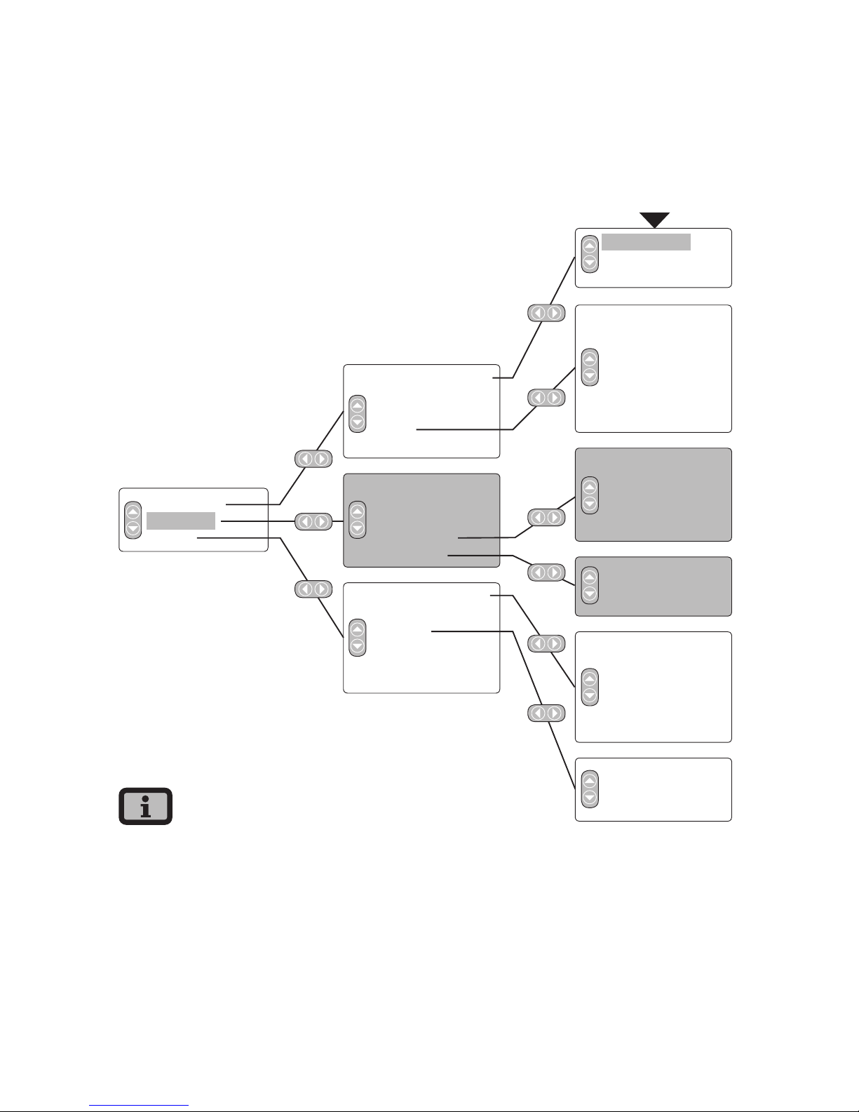
5 Operation
39
5.3 Menu structure
The menu provides access to all Solar Inverter
screens. Open the main menu by pressing the left
arrow key twice from the standard screen.
Solar Inverter
Solar system
Settings
Instantaneous values
Energy yield
Events
History
Information
Instantaneous values
Energy yield
Events
System history
System info
General information
Login
Network*
Commissioning*
Change country*
Self-testing**
Yield for week
Yield for 15 days
Yield for month
AC output
DC values
AC values
Max. output
Standard screen
Instantaneous values 1
Instantaneous values 2
Language
LCD contrast
Date/Time*
Receiving time*
Firmware*
New password*
Yield for week
Yield for 15 days
Yield for month
Total output
Max. output
Ethernet
CAN bus
Interfaces
Firmware
Memory
Mode
START
· The areas highlighted in grey are only available
in the master
· *) after entry of customer password
Standard password: ******** (= 8 times star key)
· **) This is only shown if the configured country
of installation is Italy.
Page 40
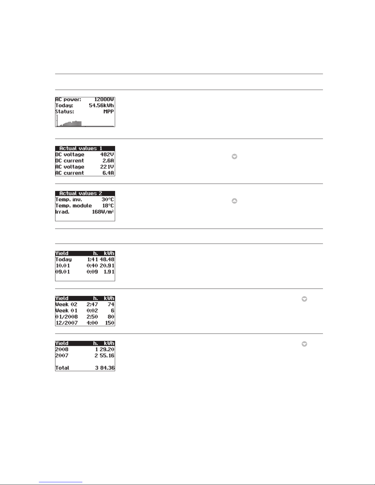
5 Operation
40
5.4 Overview of screen displays
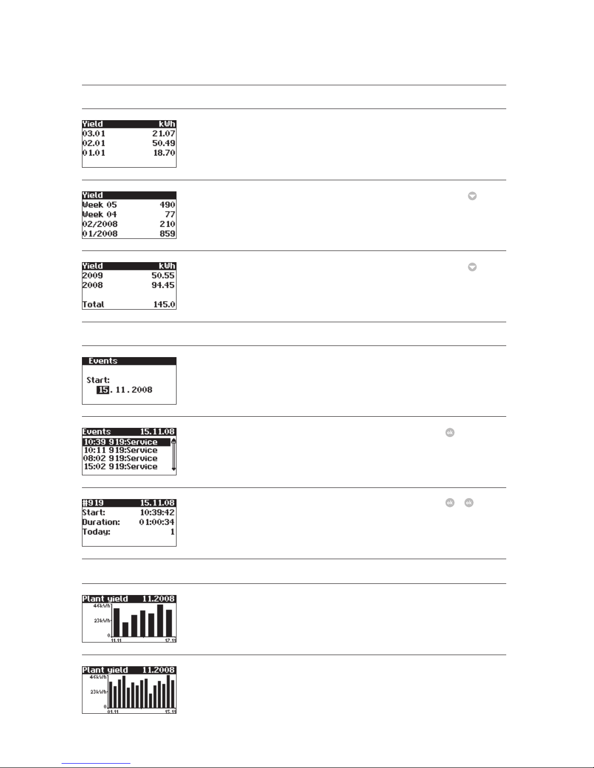
Display Description Menu selection
Instantaneous Values – Device
Current feed-in power, daily energy
yield and device status
MPP:Feeding in MPP mode
The screen appears automatically
when you have not made any entries
with the keyboard for several minutes.
Solar Inverter – Instantaneous values
Display of voltages and currents from
solar generator and grid
Solar Inverter – Instantaneous values
–
Interior temperature of device (Temp.
Inv.) and temperature and irradiation
values (if sensor is connected)
Solar Inverter – Instantaneous values
–
Instantaneous values – yields
AC yields and operating hours from
today, yesterday and the day before
yesterday
Solar Inverter - Engergy yield
AC yields and operating hours for the
current week, the previous week, the
current month and the previous month
Solar Inverter – Energy yield –
AC yields for the current year and the
previous year
Solar Inverter – Energy yield –
Page 41
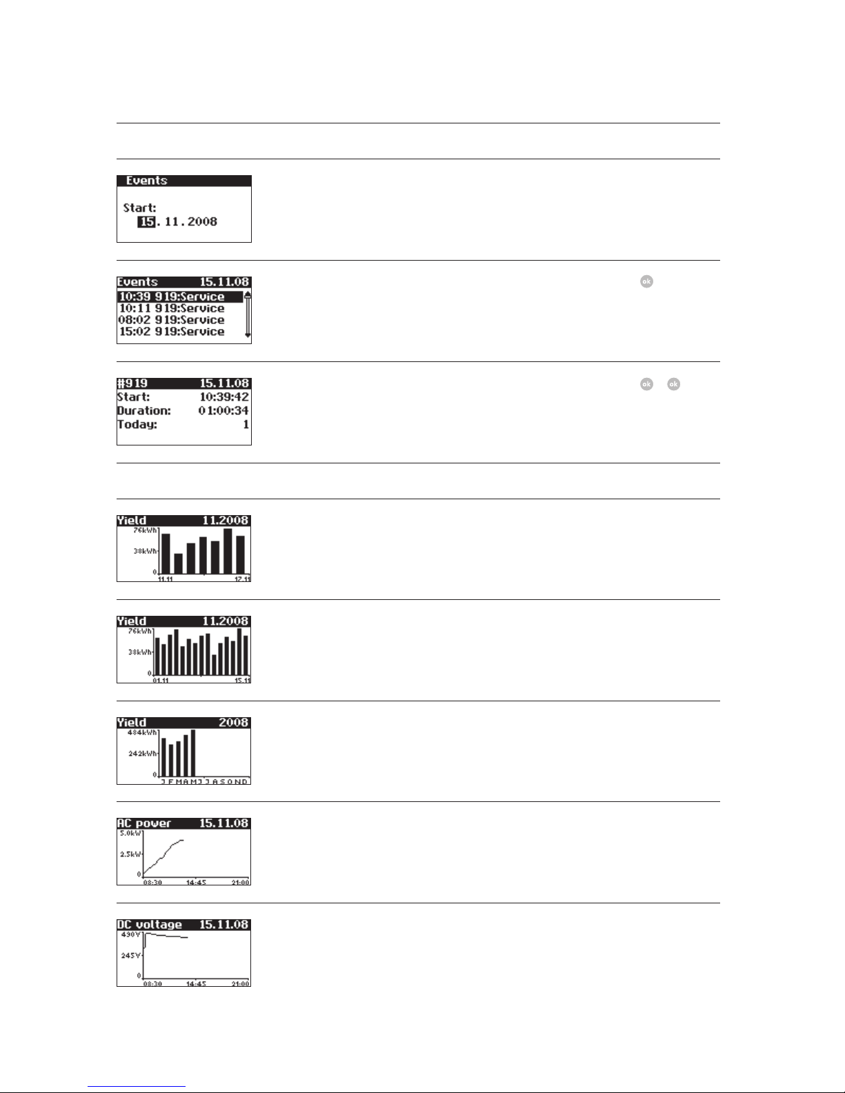
5 Operation
41
Display Description Menu selection
Events – Device
Select starting data for event display Solar Inverter – Events
Display event list Solar Inverter – Events –
Display event details (error number,
data, starting time, duration and
number of occurrences per day)
Solar Inverter – Events –
–
History – Device
Daily yield for 1 week Solar Inverter – History – Yield for
week
Daily yields for 15 days Solar Inverter – History – Yield for 15
days
Monthly yields Solar Inverter – History – Yield for
month
AC output (5-min. values) Solar Inverter – History – AC output
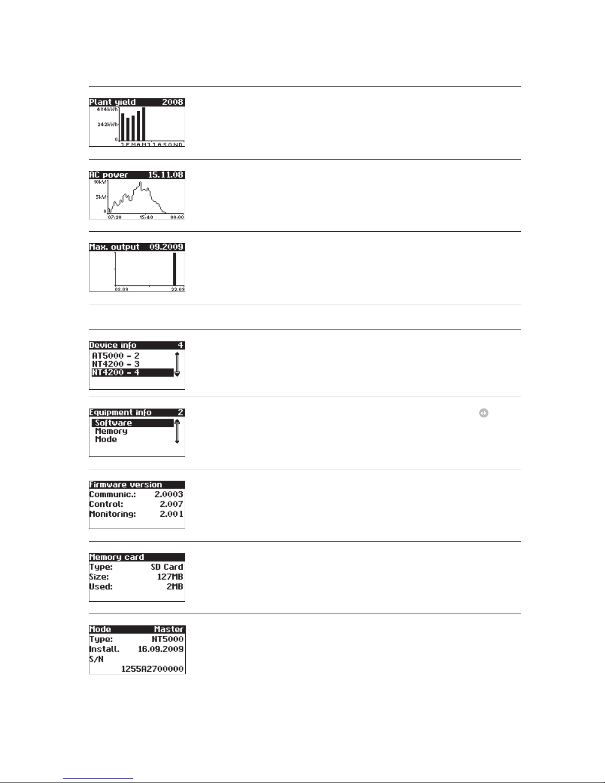
DC voltage (5-min. values) Solar Inverter – History – DC output
Page 42
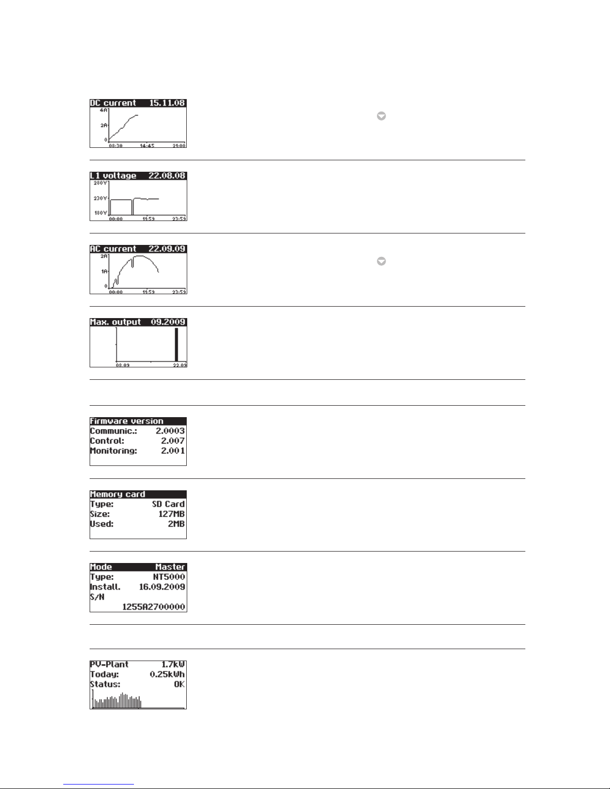
5 Operation
42
Display Description Menu selection
DC current (5-min. values) Solar Inverter – History – DC values
–
AC voltage (5-min. values) Solar Inverter – History – AC values
AC current (5-min. values) Solar Inverter – History – AC values
–
Max. output
Daily maximum values
Solar Inverter – History – Max. output
Information – Device
Firmware Solar Inverter – Information
– Firmware
Memory card Solar Inverter – Information – Memory
Device mode Solar Inverter – Information – Mode
Instantaneous values – Solar system (only on master)
Current system feed-in power, daily
energy yield and system status
The screen appears on the master
automatically when you do not make
any entries with the keyboard for
several minutes.
Solar system – Instantaneous values
Page 43
5 Operation
43
Display Description Menu selection
Yields – Solar system (only on master)
AC system yields and operating hours
from today, yesterday and Day before
yesterday
Solar system – Energy yield
AC system yields for the current week,
the previous week, the current month
and the previous month
Solar system – Energy yield –
AC system yields for the current year
and the previous year
Solar system – Energy yield –
Events – Solar system (only on master)
Select starting data for system event
display
Solar system – Events
Display event list for entire system Solar system – Events –
Display event details (error number,
data, starting time, duration and
number of occurrences per day)
Solar system – Events –
–
System history – Solar system (only on master)
Solar system daily yield for 1 week Solar system – System history – Yield
for week
Solar system daily yield for 15 days Solar system – System history – Yield
for 15 days
Page 44
5 Operation
44
Display Description Menu selection
Solar system monthly yields Solar system – System history – Yield
for month
Solar system AC output
(5-min. values)
Solar system – System history – AC
output
Maximum system output
Daily maximum values
Solar system – System history – Max.
output
System info – Solar system (only on master)
Device list for selecting a device Solar system – System info
Selection of information Solar system – System info –
Firmware Solar system – System info – Firmware
Memory card Solar system – System info – Memory
Device mode Solar system – System info – Mode
Page 45
5 Operation
45
Display Description Menu selection
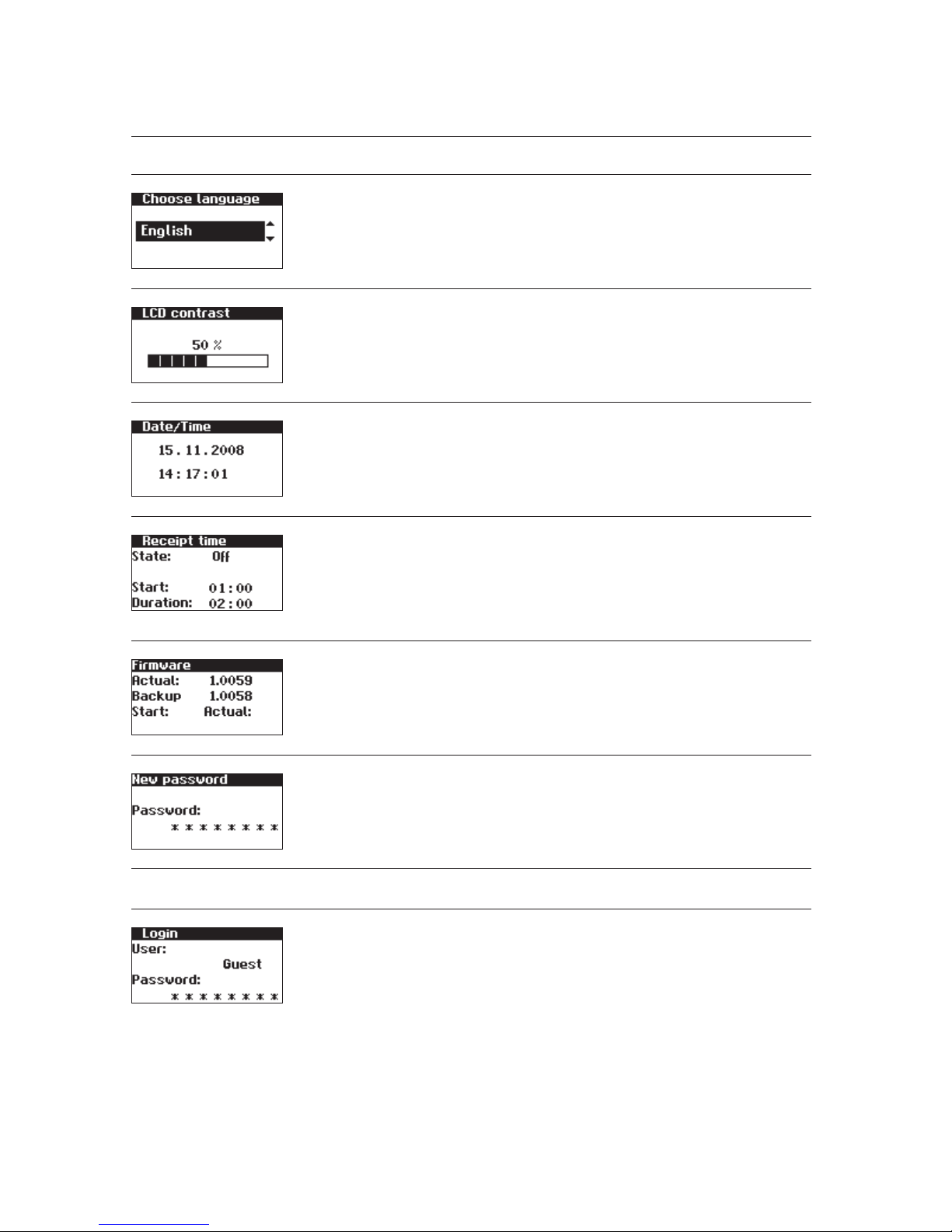
Settings – General
Display language Settings – General – Language
LCD contrast Settings – General – LCD contrast
Set date/time
(only possible with customer password)
Settings – General – Date/Time
Set receiving time (starting time and
duration in which the device can also
be addressed in the night mode via
the network).
(only possible with customer password)
Settings – General – Receiving time
Firmware versions Settings – General – Firmware
Changing the customer password
(only possible with customer password)
Settings – General – Password
Settings – Login
Password entry to access advanced settings (necessary for commissioning)
Settings – Login
Page 46
5 Operation
46
Display Description Menu selection
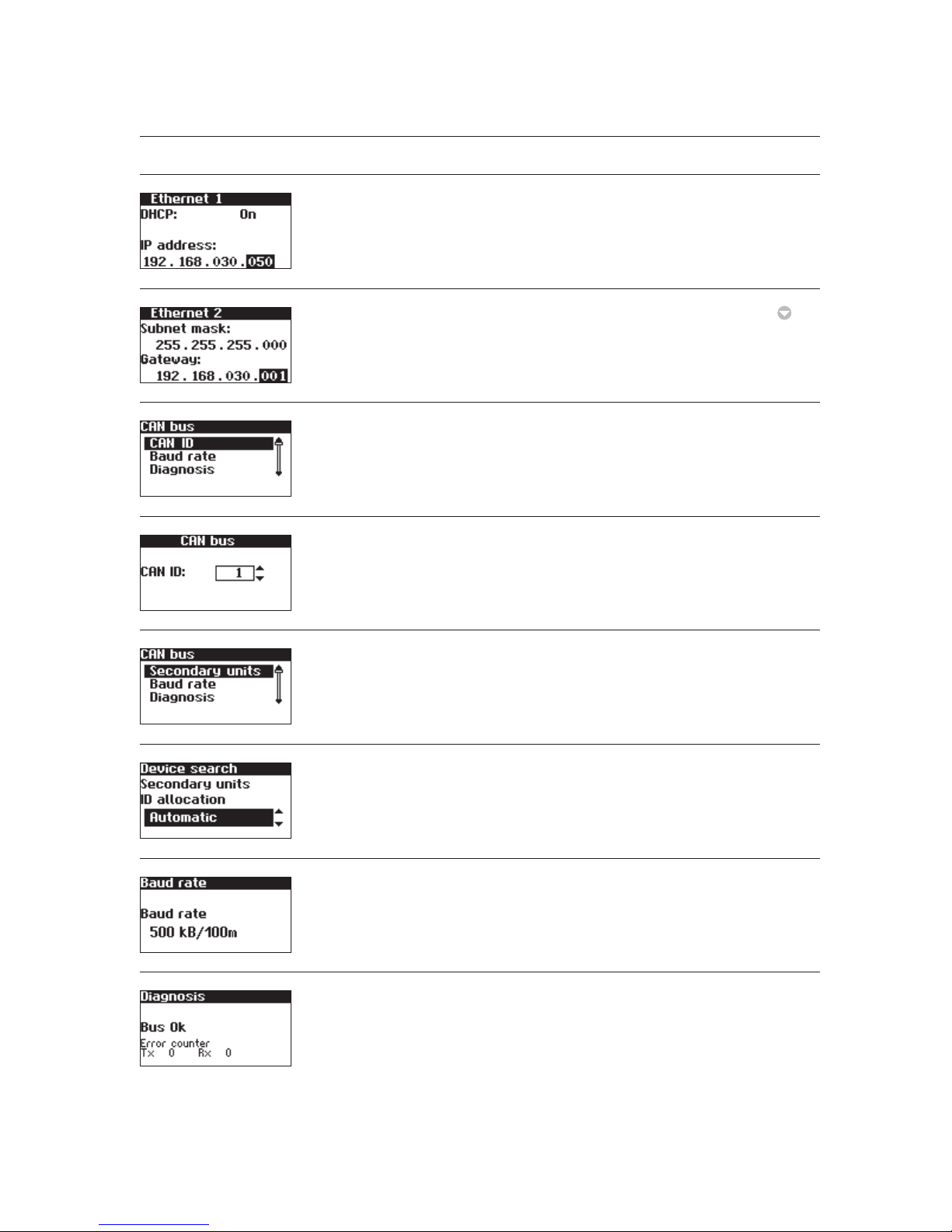
Settings – Network (only possible with customer password)
Network settings (Screen 1) Settings – Network – Ethernet
Network settings (Screen 2) Settings – Network – Ethernet –
Only for secondary unit Settings – Network – CAN bus
Only for secondary unit with manual
CAN ID setting: CAN ID request
Settings – Network – CAN bus – CAN ID
Main unit only Settings – Network – CAN bus
Selection at the main unit: type of ID
allocation for the secondary units
Settings – Network – CAN-Bus – Secondary units
Setting the baud rate Settings – Network – CAN-Bus – Baud
rate
Function test for the CAN connection Settings – Network – CAN-Bus
– Diagnostics
Page 47
5 Operation
47
Display Description Menu selection
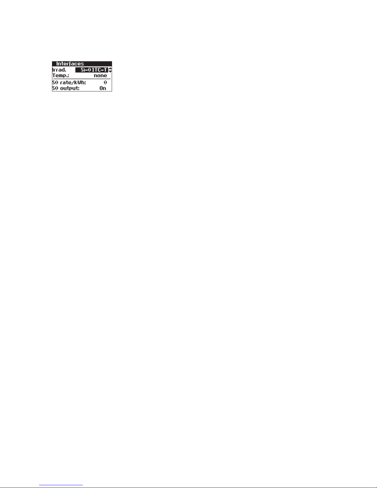
Setting of the irradiation and temperature sensor and configuration of the
S0 pulse output
Settings – Network – Interfaces
Page 48
5 Operation
48
5.5 Malfunction displays
The Solar Inverter indicates malfunctions in the LCD
display and saves these in the internal error memory.
The malfunction display consists of a number and
a short designation. Based on the first number
you can quickly recognise which area the error has
occurred in:
1: Error in the area of the solar generator
2: Error in the area of the AC network
3: Error in the area of the inverter
4: Error in the area of the interfaces/communication
5: Warnings in the area of the interfaces/
communication
9: Service error
If an error is shown in the standard display, then you
can look up the exact error message in the menu
under «Solar Inverter – Events».
· A restart may be attempted in the event of an
error message.
· Please note the serial number of the device and
the error number before contacting the Technical Hotline.
· The Technical Hotline can be contacted on
+49 (0)7531 996 77-577 during weekdays from
7:30 am to 6:00 pm.
Display message Description Cause and possible remedies
Solar generator fault
101:U-DC max Your NT Solar Inverter is approved for
a maximum open-circuit voltage of the
solar generator of 900 V. All components
of the DC input are sufficiently dimensioned with a safety factor. If the threshold is exceeded, the Solar Inverter stops
feeding.
The maximum DC voltage
was exceeded.
· Check the dimensioning of your PV
generator.
Too many modules are connected in
series.
· Reduce the number of modules and
carry out commissioning again.
102:Insulat. Before each connection, your Solar
Inverter checks the PV system for a
possible earth fault or insulation faults.
Should this kind of error be detected,
no feeding takes place. The mode of
operation is conformant with DIN VDE
0126-1-1.
The Solar Inverter has discovered an
insulation fault in the PV system during
start-up.
· Check your PV system for possible
insulation faults (pinched-off DC lines
etc).
The measured insulation resistance must
be at least 900 kohms.
Page 49
5 Operation
49
Display message Description Cause and possible remedies
103:AFI>30mA
105:AFI>60mA
106:AFI>150mA
Your Solar Inverter is equipped with a
universally sensitive AFI according to DIN
VDE 0126-1-1. This monitoring device has
detected a relative residual current jump.
A residual current jump has occurred
during operation of the Solar Inverter.
· Check your PV system for possible
insulation faults.
104:AFI>0.3A Your Solar Inverter is equipped with a
universally sensitive AFI according to DIN
VDE 0126-1-1. This monitoring device has
detected an absolute fault current of
> 300 mA.
A residual current has occurred during
operation of the Solar Inverter.
· Check your PV system for possible
insulation faults.
AC network fault
201:Surge e. Your Solar Inverter continually moni-
tors the quality of the AC grid. During
high voltage peaks on the phase feeding
in, the Solar Inverter stops feeding and
attempts a restart.
The Solar Inverter has detected a high
voltage peak on the phase feeding in.
· After malfunction elimination the
Solar Inverter restarts automatically.
Should the error occur frequently,
please contact your power supply
company.
A monitoring phase and a directly
earthed conductor were exchanged
when connecting the AC side.
202:UAC1>10% Your Solar Inverter continually monitors
the voltage level of the phase feeding
in. If the maximum permissible limit is
exceeded, the Solar Inverter stops feeding and does not start up again until the
voltage value drops below the maximum
permissible limit.
The cable cross-section in the AC supply line to the solar inverter is too small.
Your inverter feeds into a spur line,
which is insufficiently dimensioned.
· Check the design of your grid connection (energy meter) or the grid feed
point to your power supply company
(PSC).
· Ask your power supply company (PSC)
about grid stability and design.
Page 50
5 Operation
50
Display message Description Cause and possible remedies
203:UAC1>Max
205:UAC2>Max
207:UAC3>Max
Your Solar Inverter continually monitors
the voltage level of the phases L1, L2
and L3. When the maximum permissible
limit is exceeded, the Solar Inverter stops
feeding and does not start up again until
the voltage value drops below the maximum permissible limit.
The cable cross-section in the AC supply
line to the Solar Inverter is too small.
Your inverter feeds into a spur line,
which is insufficiently dimensioned.
· Check the design of your grid connection (energy meter) or the grid feed
point to your Electric Utility.
· Ask your Electric Utility about grid
stability and design.
204:UAC1<Min
206:UAC2<Min
208:UAC3<Min
Your Solar Inverter continually monitors
the voltage level of the phases L1, L2
and L3. When the minimum permissible
limit is dropped below, the Solar Inverter
stops feeding and does not start up
again until the voltage value exceeds the
minimum permissible limit. If the voltage
drops below 160 V, the Solar Inverter
cannot be supplied.
· Ask your Electric Utility about grid
stability and design.
210:Frq1>Max
211:Frq1<Min
The Solar Inverter continually monitors
the grid frequency of the phase feeding
in. If this is outside the permitted range,
the Solar Inverter stops feeding and
does not start up again until the value is
within the tolerance range.
· Ask your Electric Utility about grid
stability and design.
212:DC share Your Solar Inverter continually moni-
tors the quality of current fed in. If
an increased DC share is found in the
current fed in, the Solar Inverter stops
feeding.
· Restart the Solar Inverter.
If the error still occurs, please contact the
technical hotline. The phone number is
provided on the back of the manual.
213:UAC1>10%
(Warning)
The voltage of the phase feeding in is
higher than 10% above the nominal
value. If this is the case for longer than
ten minutes, the inverter stops feeding
and does not switch on again until the
voltage drops below this limit again.
The cable cross-section in the AC supply
line to the Solar Inverter is too small.
Your inverter feeds into a spur line,
which is insufficiently dimensioned.
· Check the design of your grid connection (energy meter) or the grid feed
point to your Electric Utility.
· Ask your Electric Utility about grid
stability and design.
Page 51
5 Operation
51
Display message Description Cause and possible remedies
224:AC P. fail Your Solar Inverter has detected a mains
power failure.
· Ask your Electric Utility about grid
stability and design.
225:UV excon
226:OV excon
You Solar Inverter is equipped with a
high-quality redundant grid monitoring
function according to DIN VDE 0126-1-1
and constantly monitors the grid. If one
of the phases fails, or if the phase position between the individual conductors
changes, the Solar Inverter stops feeding
and does not start up again until the
error is eliminated.
· Check phases L2 and L3.
· Ask your power supply company (PSC)
about grid stability and design.
227:L1 Your Solar Inverter continuously moni-
tors the output current. Excessive current
rise was detected.
· Ask your power supply company (PSC)
about grid stability and design.
Inverter fault
301:AFI over The integrated sensor for measuring
the residual current has been operated
outside its measuring range.
A residual current was detected during
start-up.
· Restart the Solar Inverter.
If the error still occurs, please contact the
technical hotline. The phone number is
provided on the back of the manual.
303:Overtmp. Your Solar Inverter is designed for an
ambient temperature of up to +45°C.
When a specified temperature threshold
of the heat sink is reached, the output power is reduced linearly. Should
the heat sink temperature nevertheless continue to increase, feeding is
stopped. After the heat sink temperature
drops, the Solar Inverter starts up again
automatically.
The maximum permissible ambient temperature has been exceeded.
· The installation location is not suitable. Please find another installation
location.
The necessary air circulation was not
taken into account during installation.
· Clean the Solar Inverter, if dirt prevents cooling.
· Observe the installation distances
specified in the manual.
Objects were laid on the heat sink and
unimpaired convection was prevented.
· Remove the objects.
Page 52
5 Operation
52
Display message Description Cause and possible remedies
304:Grid re. The NT Solar Inverter checks the opera-
tion of the mains relay prior to every
switch-on. An error was detected during
this check.
· Restart the Solar Inverter.
If the error still occurs, please contact the
technical hotline. The phone number is
provided on the back of the manual.
305:AFI test The NT Solar Inverter checks the opera-
tion of its residual-current monitoring
device prior to every switch-on. An error
was detected during this check.
· Restart the Solar Inverter.
If the error still occurs, please contact the
technical hotline. The phone number is
provided on the back of the manual.
306:T. meas. The NT Solar Inverter is equipped with
a temperature sensor that monitors the
heat sink temperature. This message
appears if the sensor reports a value outside its value range or in case of a sensor
cable break.
The ambient temperature of the Solar
Inverter is outside the permissible range
(< -25°C).
· Wait until the temperature reaches
the permissible operating range.
A cable break has occurred in the
sensor which monitors the heat sink
temperature.
· Please contact the technical hotline.
The phone number is provided on the
back of the manual.
307:Overtmp.
(Warning)
Your Solar Inverter is designed for an
ambient temperature of up to +45°C.
When a specified temperature threshold
of the heat sink is reached, the output
power is reduced linearly. Should the
heat sink temperature nevertheless
continue to increase, feeding is stopped.
This warning appears when the current
heat sink temperature is just below the
switch-off threshold.
The maximum permissible ambient temperature has been exceeded.
· The installation location is not suitable. Please find another installation
location.
The necessary air circulation was not
taken into account during installation.
· Clean the Solar Inverter, if dirt prevents cooling.
· Observe the installation distances
specified in the manual.
Objects were laid on the heat sink and
unimpaired convection was prevented.
· Remove the objects.
Page 53
5 Operation
53
Display message Description Cause and possible remedies
308:M incom
309:Control
The software version of the control and
the monitoring software is incompatible.
· Carry out a software update.
310:no config No country is set. Contact the technical hotline for the
installer password. (The phone number
is provided on the back of the manual.)
Reset the country according to the
explanatory note 4.2 Commissioning,
page 29
Interface/communication fault
401:SD card The Solar Inverter cannot find an SD
card.
· Restart the Solar Inverter.
If the error still occurs, please contact the
technical hotline. The phone number is
provided on the back of the manual.
402:SD card The SD card is write-protected. · Restart the Solar Inverter.
If the error still occurs, please contact the
technical hotline. The phone number is
provided on the back of the manual.
403:CAN user Communication error with CAN user. · Check whether an error has occurred
in the CAN slave. Restart slave and
master if necessary.
404:CAN bus CAN bus not in operation. No communication is possible via the
CAN bus.
· Check the bus lines and the terminating resistors.
· Check whether the maximum permissible line lengths have been complied
with.
· Check whether the bus lines have
been routed parallel to power cables.
Separate bus lines and power cable
from each other spatially if necessary.
Page 54
5 Operation
54
Display message Description Cause and possible remedies
405:CAN user CAN user does not respond. · Check whether an error has occurred
in the CAN slave. Restart slave if
necessary.
406:file def Language file could not be loaded. · Restart your Solar Inverter. Carry out
a software update for the language
file.
407:file def Website could not be loaded. · Restart your Solar Inverter. Install the
latest file for the website via a software update.
408:file def File with error messages could not be
loaded.
· Restart your Solar Inverter. Install the
latest error messages file via a software update.
Communication warnings
501:Solar
(Warning)
No sensor found on sensor channel 1
(solar).
If you have connected a sensor:
· Check the connection to your sensor.
If you have not connected a sensor:
· Check the configuration with the
Sunways Browser.
502:Temp.
(Warning)
No sensor found on sensor channel 2
(temperature).
If you have connected a sensor:
· Check the connection to your sensor.
If you have not connected a sensor:
· Check the configuration with the
Sunways Browser.
503:CAN com.
(Warning)
Communication malfunctions occur
repeatedly on the CAN bus.
A malfunction occurs in the data transmission on the CAN bus. However, a data
exchange continues to be possible.
· Check whether all connectors of the
bus lines and the terminating resistors are properly mounted.
· Check whether the bus lines have
been routed parallel to power cables.
Separate bus lines and power cable
from each other spatially if necessary.
Page 55
5 Operation
55
Display message Description Cause and possible remedies
504:CAN cfg.
(Warning)
CAN bus is in the configuration mode.
No measured values are transferred.
At least one device is in the menu item
«Settings – Network – CAN bus».
· Close this menu for all devices.
505:SMPT ser.
(Warning)
Warning: SMTP server cannot be
reached.
Fault during e-mail delivery.
Re-attempt e-mail delivery.
· If the fault recurs check the e-mail
settings via the Sunways Browser
506:SMTP soc.
(Warning)
Warning: SMTP no socket available.
507:SMTP cm.
(Warning)
Warning: SMTP faulty communication
with server.
508:DNS fehl.
(Warning)
Warning: DNS has failed. Communication fault between the
integrated web server and an Internet
browser in conjunction with the Sunways
Browser.
These warnings are non-critical and
can be ignored if they only occur
occasionally.
These warnings have no influence on the
energy production of the inverter.
509:HTTP con.
(Warning)
Warning: HTTP client connection has
failed.
510:HTTP aut.
(Warning)
Warning: HTTP client authorisation has
failed.
511:HTTP tim.
(Warning)
Warning: HTTP client timeout.
512:HTTP soc.
(Warning)
Warning: HTTP client no socket available.
513:HTTP soc.
(Warning)
Warning: HTTP client error with socket.
514:HTTP met.
(Warning)
Warning: HTTP client incorrect method.
515:HTTP pro.
(Warning)
Warning: HTTP client error with protocol.
516:HTTP wr.
(Warning)
Warning: HTTP client write error.
517:HTTP re.
(Warning)
Warning: HTTP client read error.
Page 56
5 Operation
56
Display message Description Cause and possible remedies
518:CAN init.
(Warning)
Warning: CAN initialisation error. CAN bus initialisation fault during device
startup.
· Restart the Solar Inverter.
If the error persists, please contact the
technical hotline. The phone number is
provided on the back of the manual.
519:Time syn
(Warning)
Warning: Time synchronisation with the
NTP server has failed.
Firewall port 123 is blocked.
· Select an alternative time server.
Service fault
9xx: Service
fault
9xx: Service
warning
A service fault has occurred. · Disconnect the Solar Inverter from
the grid and from the solar generator
and reconnect it.
If the error occurs again, please contact
the Technical Hotline. The phone number
is provided on the back of the manual.
Page 57
57
6 System monitoring
6.1 General information
The basis for the system monitoring is the data logger integrated in the NT Solar Inverter. The Solar
Inverters of the NT series are equipped with a broad
range of monitoring options for your solar system:
· The Sunways Browser offers the display of
instantaneous values, stored operating data and
settings.
· With active alerting information about faults in
the solar system can be sent to a selected recipient via e-mail.
· With the Sunways Portal connection the NT Solar
Inverter can send the operating data of your
solar system to the Sunways Portal daily without
additional hardware. This enables you to track
your yields via the Internet.
To enable access to the system monitoring data, the
Solar Inverter must be networked via the Ethernet
connection. Three different networking options are
available:
· Direct connection via an Ethernet cable (see
chapter 6.3 Direct Ethernet connection, page 58)
or internal network (see chapter 6.6 Connection
via an existing Ethernet network, page 62)
With a direct connection or an internal network
without gateway to the Internet the Solar Inverter is
unable to send e-mails. Portal connection and active
alerting is therefore not possible.
· Connection via the Internet, e.g. connection of
the Solar Inverter to a DSL connection (see chapter 6.7 Remote access via a DSL router, page 63)
· Connection via a Sunways Modem (see chapter
6.8 Connection via the Sunways Modem, page 63)
6.2 Integrated data logger
The integrated data logger of the NT Solar Inverter
stores the operating data of your solar system. In
addition to 5-minute mean values, energy yields are
also stored as 5-minute, daily, weekly, monthly and
annual values. Up to 200 status changes (warnings
and errors with start and end) are also stored. Each
data record contains the data and time. The data
logger is designed as a circulating memory, i.e. the
respective oldest data are overwritten with new
data.
Operating data (5-min. mean values)
Number Value
4500 DC current
4500 DC voltage
4500 AC current
4500 AC voltage
4500 AC output
4500 Device temperature
4500 Module irradiance (optional)
4500 Module temperature (optional)
With this data memory volume approx. 30 days’
worth of values can be stored before the first value
in the ring buffer is overwritten again.
Energy yields (for 20 years except for minute
values)
Number Value
4500 5-minute yield
7300 Daily yield
250 Monthly yield
20 Annual yield
1 total yield since commissioning
Status messages
Number Value
200 Status changes
Page 58
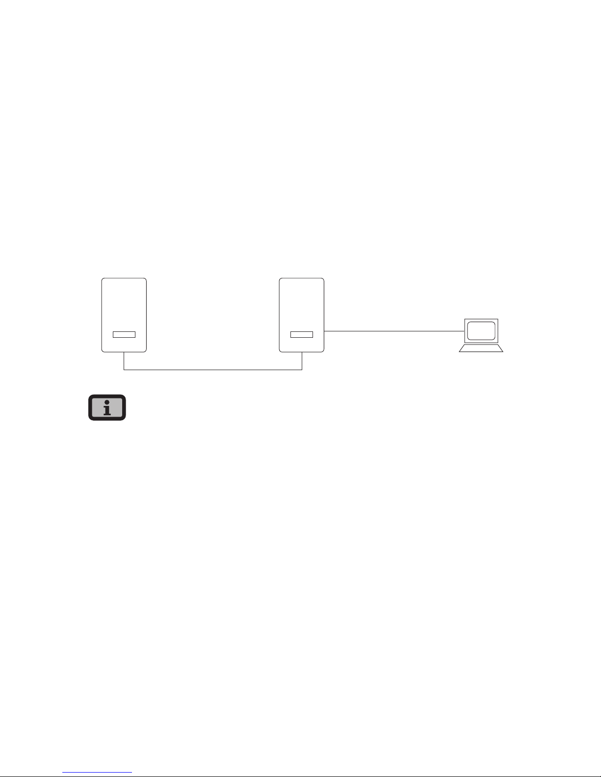
6 System monitoring
58
6.3 Direct Ethernet connection
The Solar Inverters are equipped with an Ethernet
interface as standard for system monitoring and
configuration with a PC.
Connect your PC and the Solar Inverter with the
included Ethernet cable. X-patch cables can also be
used.
The PC is connected to the master as standard. Basically all Solar Inverters – including Solar Inverters
configured as secondary units or single units – dispose of an own web server so that a connection can
be established with each device.
PC
MasterSlave
Max. Ethernet
connection: 100 m
Max. total CAN bus length:
500 m
INVERTER
INVERTER
· To always find the suitable configuration for
installation and commissioning on the PC, we
recommend the use of a second network card
(e.g. PCBus, PCMCIA), which you can configure to
match the default setting of the Solar Inverter.
· The PC and the Solar Inverter must have suitable
IP addresses and net masks. The network settings can be adjusted either directly on the Solar
Inverter via the LCD display or on your PC.
· If two network cards are used the IP addresses
must be in separate subnets, e.g. 192.168.30.XXX
and 192.168.40.XXX.
Page 59
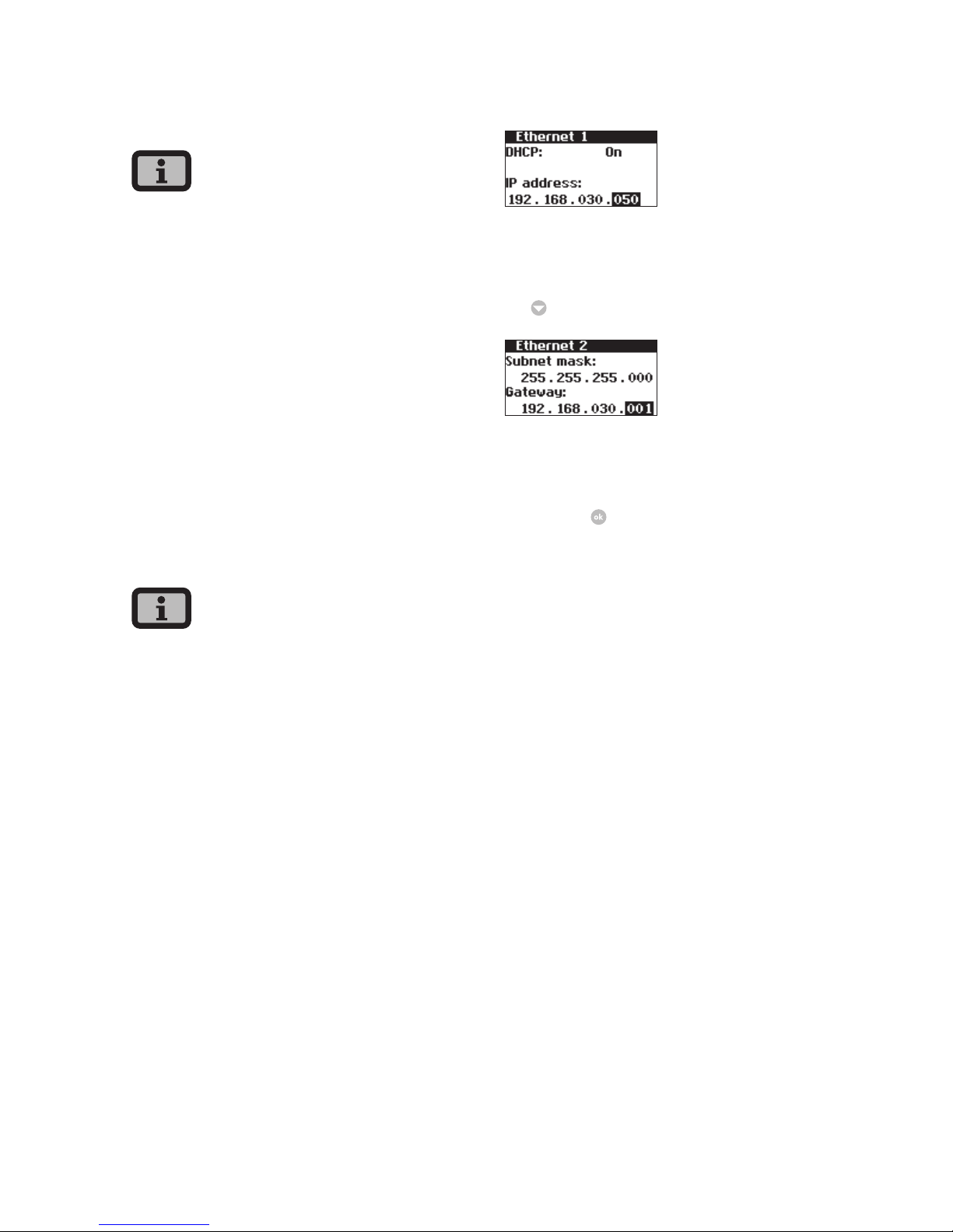
6 System monitoring
59
6.4 Network settings on Solar Inverter
· The Solar Inverter is supplied with the following,
preset IP address: 192.168.30.50
· In the default setting the Solar Inverter does
not support a DHCP (Dynamic Host Configuration Protocol). Therefore, the IP address is not
assigned automatically. It is possible to activate
the DHCP protocol via the Settings menu.
· IP addresses may only be assigned once within
the network.
If required you can assign your own IP address for
the Solar Inverter via the Settings menu.
1. Open the menu «Settings – Login».
2. Enter the default password (******** = 8 times
star key) or your chosen password.
Please note:
Numerals from 0 – 9 and letters from a – z and from
A – Z are admissible.
The password always has 8 characters. If the password you choose is fewer than 8 characters in
length, the remainder, up to the full 8 characters, is
filled with “*” symbols.
For example:
You choose “Solar” as your password. This password
has 5 characters. The system therefore then automatically adds three “*” symbols, meaning that your
password becomes “Solar***”.
3. Open the menu «Settings – Network – Ethernet».
4. Enter an IP address suitable for use with your PC.
This means the first three number blocks must be
identical, and the last number block different.
Example:
If your PC has the IP address 192.168.1.1, enter
192.168.1.2 for your Solar Inverter
5. Use
to access further settings.
6. Enter the subnet mask 255.255.255.0.
7. Enter the IP address of your PC in the gateway.
8. Confirm with
.
After the network configuration is completed you
can start the Sunways Browser by entering the IP
address of the Solar Inverter in the address line of
your web browser.
Page 60
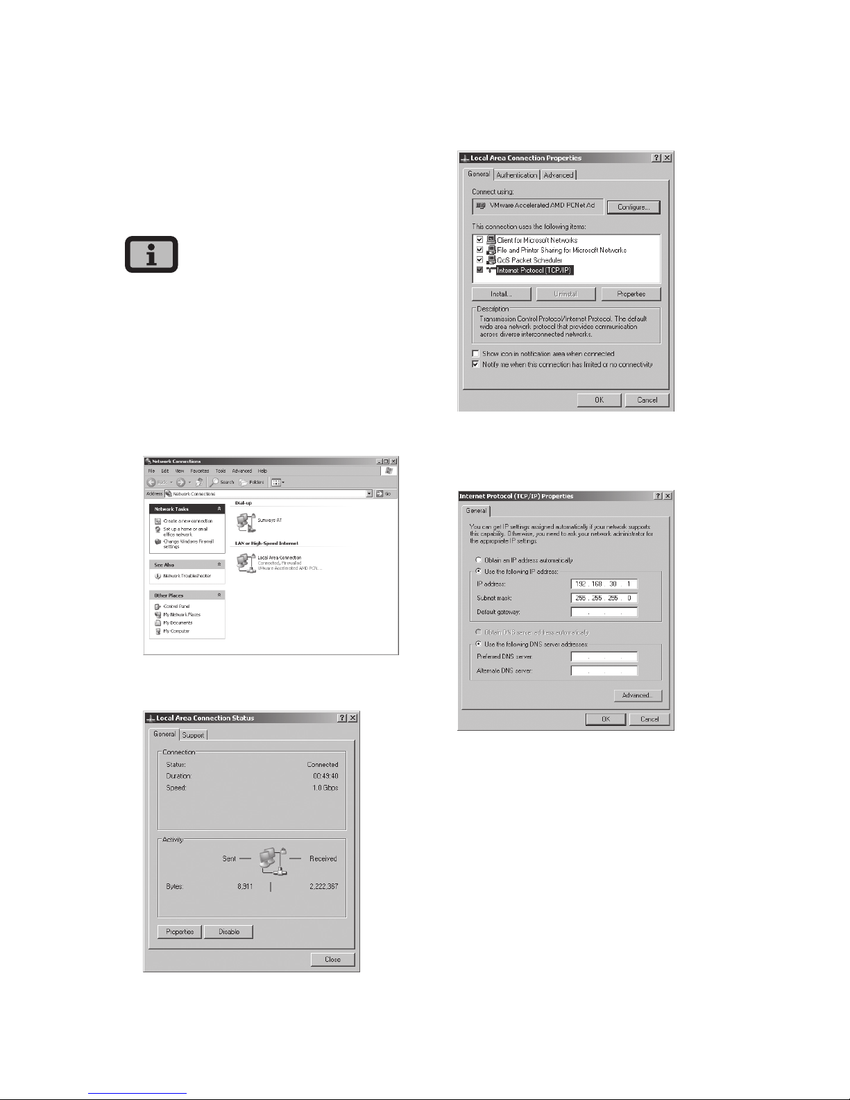
6 System monitoring
60
6.5 Network settings on the PC
To enable your PC to communicate with the Solar
Inverter certain network settings are required.
The procedure differs slightly depending on the
operating system. A configuration example for
Windows
®
XP is shown below..
IP addresses may only be assigned once within the
network.
1. Select «Start – Settings».
2. Select «Network Connections».
3. Double-click on the LAN connection through
which you are connected to the Solar Inverter.
4. Click in the Status window on «Properties».
5. Select «Internet Protocol (TCP/IP)» and click
«Properties» again.
6. Now assign an unused IP address 192.168.30.XXX
and enter the subnet mask 255.255.255.0.
7. Click OK to confirm your entries.
Page 61
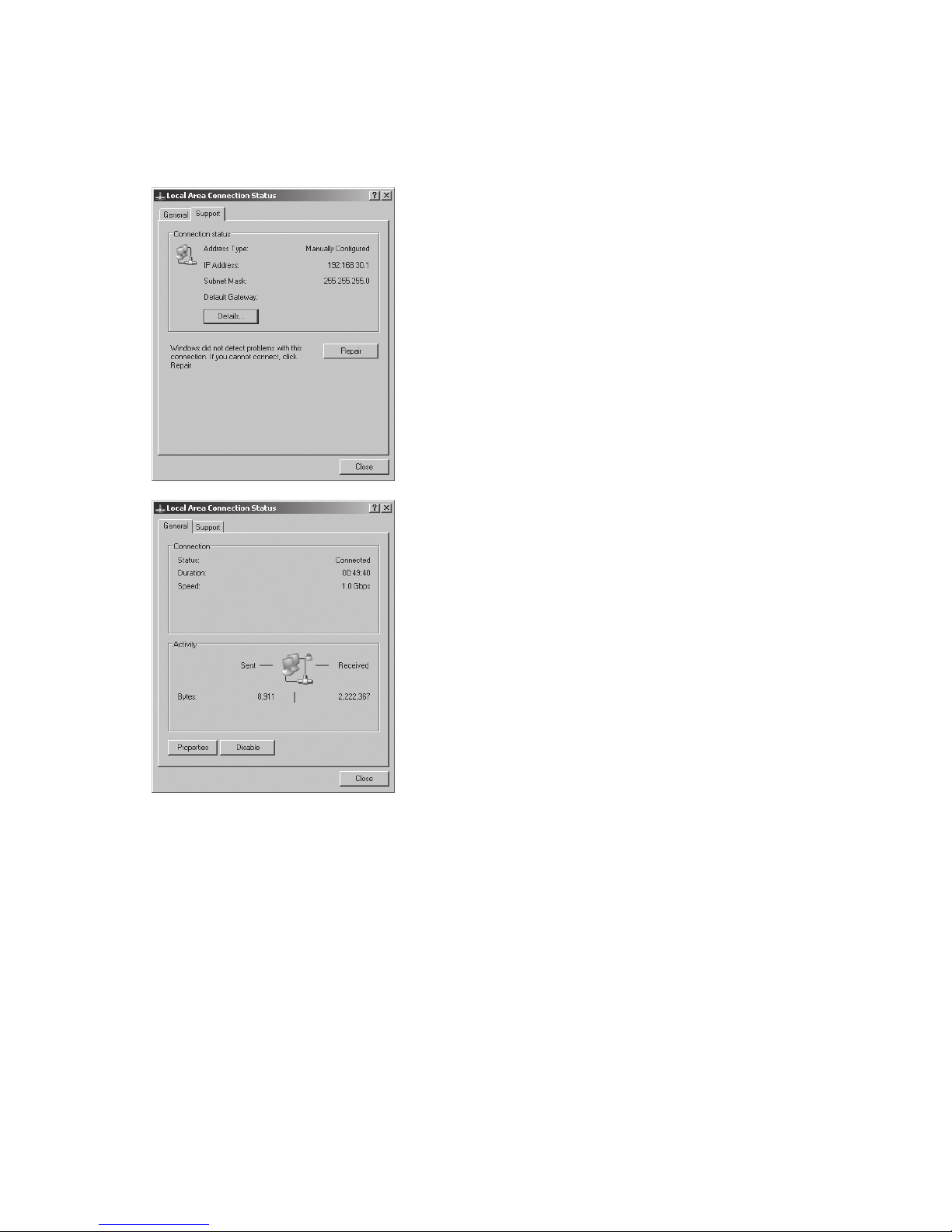
6 System monitoring
61
8. In the «Status» menu item you can check the
correctness of your entries and the status of your
connection
After the network configuration is completed you
can start the Sunways Browser by entering the IP
address of the Solar Inverter in the address line of
your web browser.
For more complex network configurations please
contact your network administrator.
Page 62
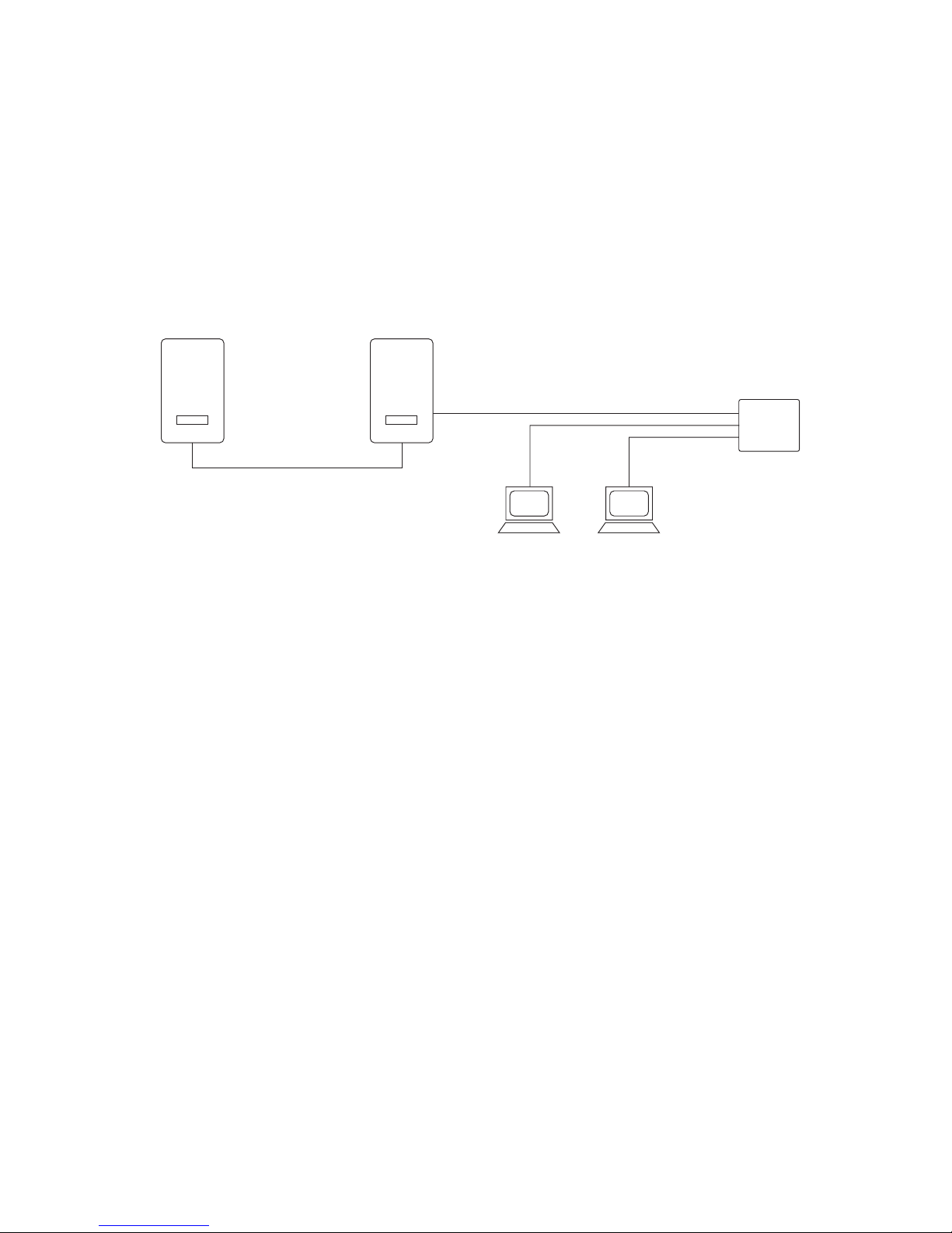
6 System monitoring
62
6.6 Connection via an existing Ethernet network
If an existing home or company network is available
you can integrate the NT Solar Inverter directly in
the network as a network device.
Connect your PC and the Solar Inverter with a CAT5
Ethernet cable with 1:1 RJ45 sockets.
The master is connected to the network as standard.
PC
PC
MasterSlave
Max. total CAN bus length:
500 m
INVERTER
INVERTER
Hub
Switch
Router
Max. Ethernet connection:
100 m
With DHCP
If a DHCP server is present in your network, you can
activate DHCP on the Solar Inverter. In this case the
Solar Inverter obtains the network settings automatically. You can display the assigned IP address via the
LCD display (menu «Settings – Network – Ethernet»)
Without DHCP
If there is no DHCP server in your network, you must
set an unused IP address on the NT Solar Inverter
(see section Solar Inverter network setting settings).
Ask your network administrator for suitable settings
for IP address, net mask and gateway.
After the network configuration is completed you
can start the Sunways Browser by entering the IP
address of the Solar Inverter in the address line of
your web browser.
Page 63
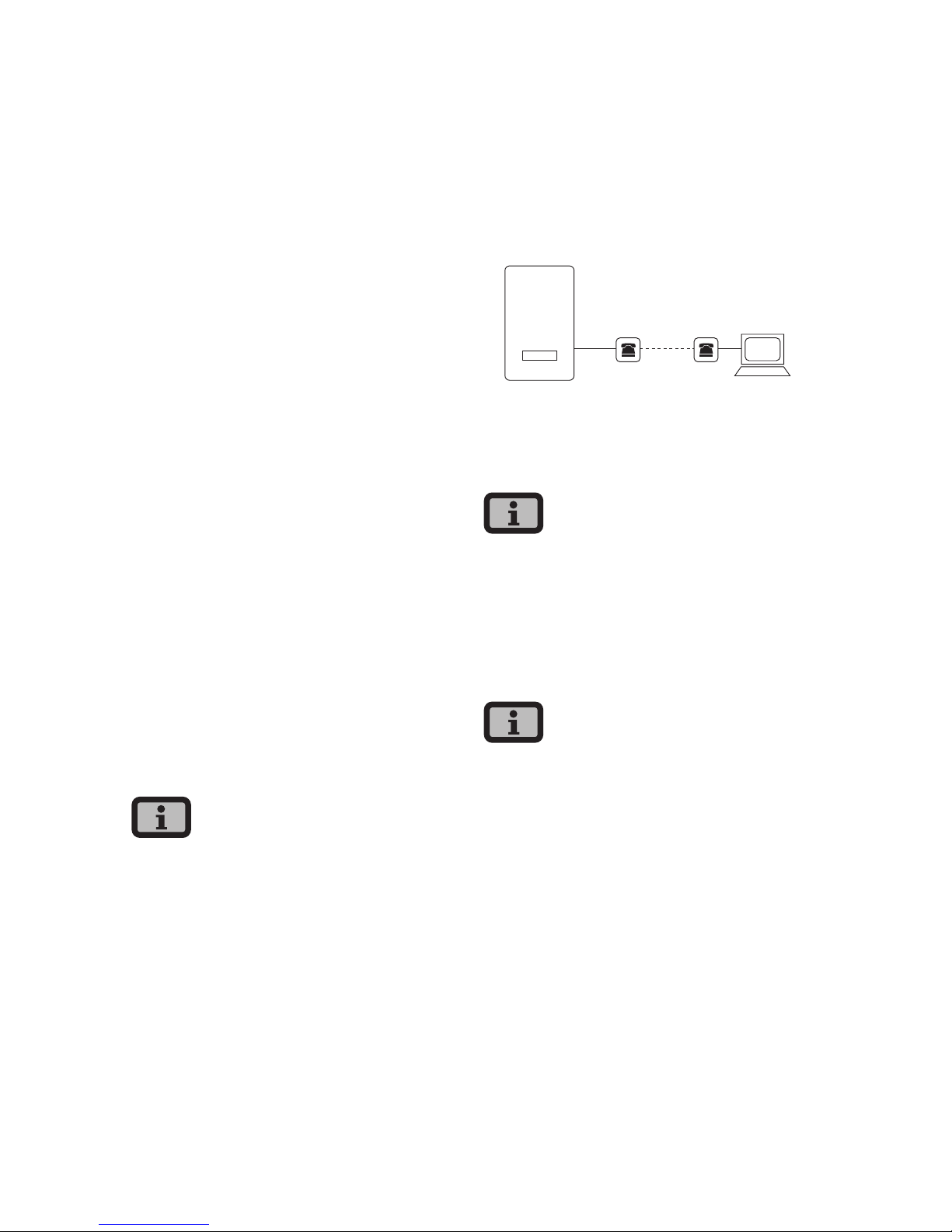
6 System monitoring
63
6.7 Remote access via a DSL router
If a DSL connection or a network with Internet
access is available you can make the Solar Inverter
accessible via the Internet.
Requirement:
Your DSL modem or Internet router supports static
IP address services, e.g. www.dyndns.org
Your router supports port forwarding.
1. Connect your Solar Inverter with your DSL router.
Use a CAT5 Ethernet cable with 1:1 RJ45 sockets.
The master is connected to the network as
standard.
2. Register free of charge at www.dyndns.org, for
example
3. Create an alias for accessing your Solar Inverter,
e.g. nt-sunways.dyndns.org. You can then access
your Solar Inverter via this address.
4. Configure your DSL router such that the IP
address is regularly reported to www.dyndns.org
(follow the procedure described in the manual
for your DSL router for this purpose).
5. Configure your DSL router such that it accepts
requests from the Internet via Port 80, for example, and forwards them internally to the Solar
Inverter (port forwarding).
6. Also note that the port for access from the Internet set in your firewall must be enabled.
Instructions for configuring common DSL routers
are available for download from the Sunways AG
website.
6.8 Connection via the Sunways Modem
A modem connection can be used to bridge longer
distances during system monitoring and configuration. Connect the Sunways Modem with the Solar
Inverter. The Sunways Modem is available as an
analog, ISDN and GSM type.
PC
INVERTER
max. 100 m
Modem Modem
1. Connect your the Solar Inverter and your PC with
a crossed or 1:1 Ethernet connection cable, type
CAT5 with RJ45 sockets.
In a networked system only the master should be
connected to the remote modem as standard.
2. Connect an external modem to your PC or, if
available, use the internal modem of the PC.
For commissioning please refer to the Sunways
Modem user manual.
The following modem combinations are permitted:
ISDN – ISDN
analog – analog
analog – GSM
GSM – analog
GSM – GSM
Page 64
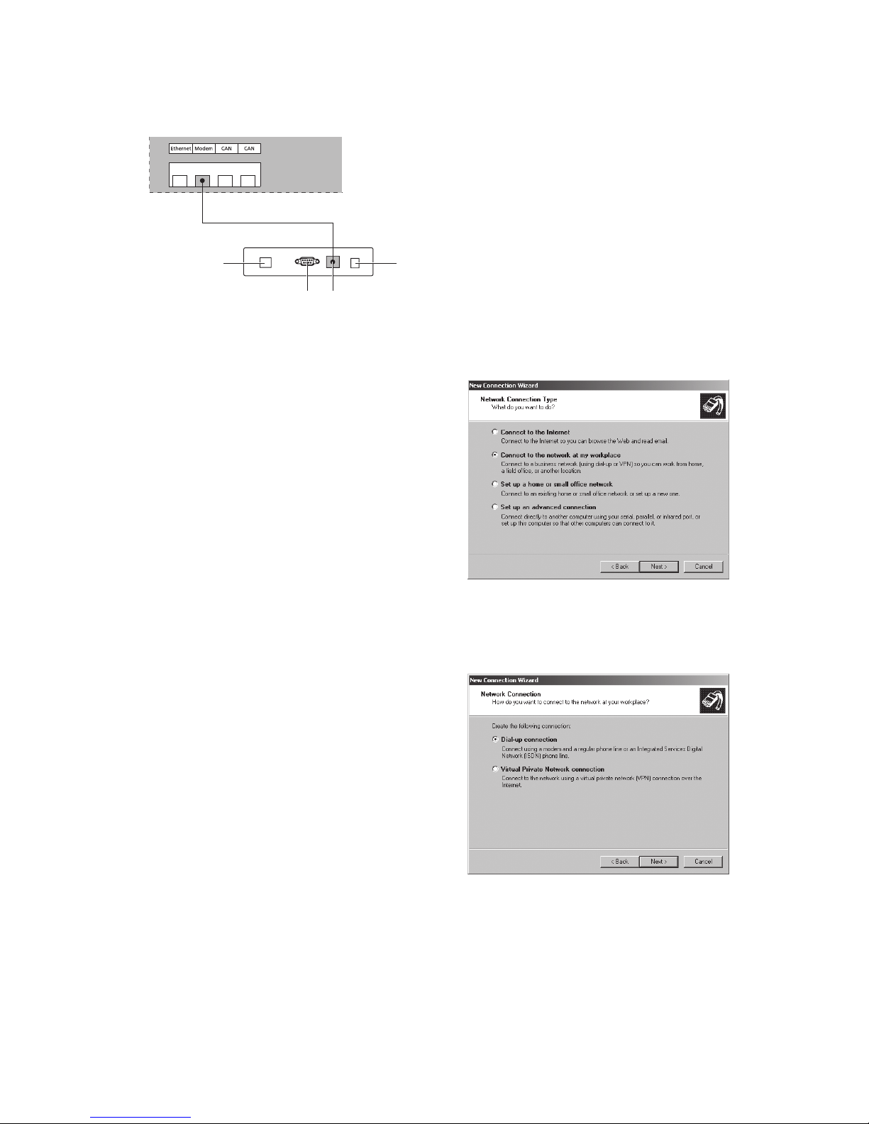
6 System monitoring
64
Connecting a Sunways Modem
41
2 3
INVERTER
MODEM
1 Telephone connection
2 RS232 interface
3 LVDS for NT and PT Solar Inverters
4 Power supply device
6.9 Dial-up connection from a PC to the Solar
Inverter
To establish a connection between your Solar
Inverter and a PC via the modem you have to establish a dial-up connection in Windows. The procedure
under Windows
®
XP is described below.
1. Run the wizard for a new connection via Start –
Settings – Network Connections.
Click «Next» to open the first selection screen.
2. Select «Connect to the network at my
workplace».
3. Confirm your selection with «Next» and select
«Dial-up connection» on the next screen and
confirm with «Next».
Page 65
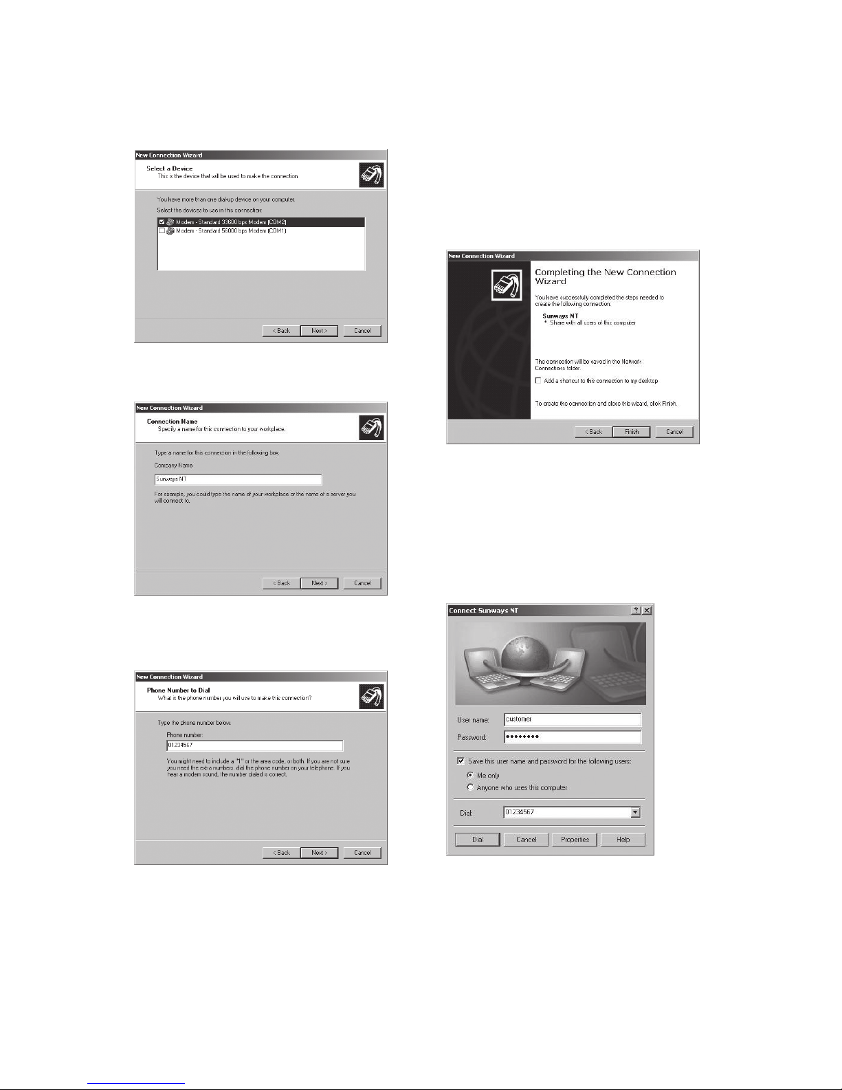
6 System monitoring
65
4. A list of installed modems appears. Select the
required modem and click «Next».
5. Enter a connection name and click «Next».
6. Specify the phone number for your Sunways
Solar Inverter.
When entering the telephone number, you may
have to include one or more digits to connect
to an outside line. (An outside line is usually
obtained by placing a «0» before the actual telephone number.)
Click «Next».
7. You can now specify whether this connection is
available to all users of this PC. If in doubt, enter
«all users» and click «Next».
8. Click the checkbox to place a shortcut on your
desktop and click «Finish».
9. The connection window appears automatically once the connection has been established.
(Alternatively via the icon on your desktop or via
«Start – Settings – Network Connections».)
Further settings are required in the «Properties»
section.
Page 66
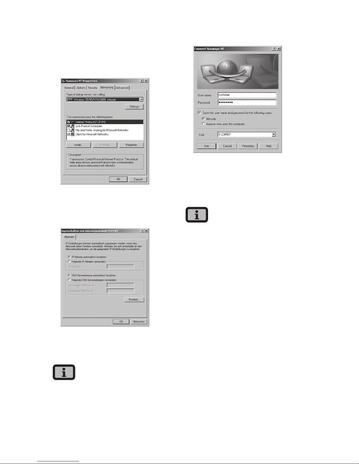
6 System monitoring
66
10. First click the «Networking» tab and select
«Internet Protocol (TCP/IP)».
Select «Properties».
11. Enter the following data:
Obtain an IP address automatically
Obtain DNS server address automatically
12. Enter «customer» as the user name and the
standard password (******** = 8 times star key)
or the password you entered previously.
The password matches the customer password on
the device.
13. Click «Dial» to establish the connection. After
the connection is established you can start the
Sunways Browser by entering the IP address of
the Solar Inverter in the address line of your web
browser.
In contrast to the normal IP address for a modem
connection the IP address of the Solar Inverter is set
to 192.168.20.50 by default.
Page 67
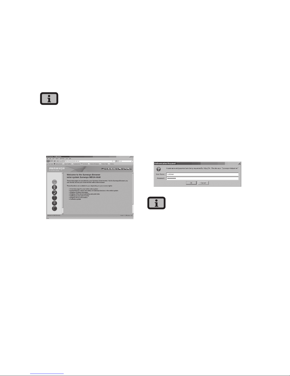
7 Sunways Browser
6767
7 Sunways Browser
7.1 General information
The Sunways Browser can be called up via a standard Internet browser, e.g. Mozilla Firefox. One of
the four possible connections between a PC and the
Solar Inverter is required for this purpose (see chapter 6 System monitoring, page 57)
Please note: Your browser must be set to UTF-8 character coding in order to ensure that all characters
are displayed correctly.
The start screen opens once the IP address of the
Solar Inverter has been entered in the address line
of the browser:
Here you can select from eleven different languages.
The browser offers the following functions:
· Display of the operating mode and instantaneous values for a single device or for a CAN-networked system
· Display of energy yields as 5-minute, daily,
monthly, annual and total values
· 5-minute mean values of solar generator current
and voltage, grid current and voltage and feedin power
· Settings, e.g. for date/time, interface configuration, alerting options, communication parameters etc.
· Configuration of the output control parameters
according to the German Renewable Energy Act
and the Low- and Medium-Voltage Directive
· Communication software update (LCD display, interfaces,communication and Sunways
Browser) and the control software (control and
monitoring)
7.2 Access protection
The Sunways Browser is provided with password
protection so that unauthorised persons cannot
access your Solar Inverter.
The following user data are set in the delivered
state:
User: customer
Password: * * * * * * *
· It is recommended that you change this pass-
word to an 8-digit/character password.
· This password is identical to the password
entered via the LCD display for settings and
commissioning.
· Numerals from 0 – 9 and letters from a – z and
from A – Z are admissible.
· The password always has 8 characters. If the pass-
word you choose is fewer than 8 characters in
length, the remainder, up to the full 8 characters,
is filled with “*” symbols.
· For example:
You choose “Solar” as your password. This password has 5 characters. The system therefore then
automatically adds three “*” symbols, meaning
that your password becomes “Solar***”.#
Page 68
7 Sunways Browser
68
· If you cannot remember the password you can
request a device-specific password from the
Technical Hotline +49 (0)7531 996 77-577 so that
you can access your Solar Inverter again. In this
case you need the serial number and the MAC
address, which can be found on the type label.
7.3 Overview – Menu
Home – Displays the start page
Solar Inverter – Displays the instantaneous
values, stored operating data, Solar Inverter
status
Solar System – Displays a system overview
with status, total output, yields and access
to slaves (only available if the device is connected with the master).
Information – Device information, e.g. serial
number
Settings and software update for the device
or the networked system
System information for your solar sys-
tem such as name, capacity, geographical
location, a photograph and details of the
components.
7.4 Language selection
You can display the web pages in the following
eleven languages. Click on the respective country
flag to select the language.
· German
· English
· Spanish
· Italian
· French
· Greek
· Czech
· Slovenian
· Portuguese
· Dutch
· Bulgarian
Page 69
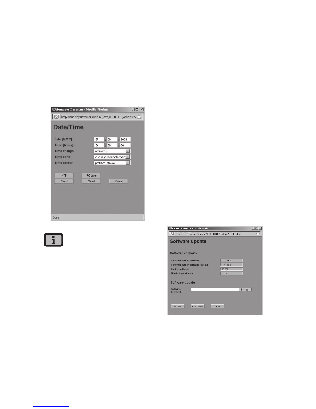
7 Sunways Browser
69
7.5 Setting the date/time
This function can be accessed via Settings – Date/
Time. If you have selected the correct time zone and
an Internet connection is available, you can automatically synchronise the time of the Solar Inverter
with a time server with the NTP button.
Alternatively you can transfer the PC time to the
Solar Inverter.
Please proceed with caution for time settings, as
they directly affect data logging. For example, if you
set the time back by 1 hour, then the existing data
for the last hour will be overwritten.
7.6 Software update
The software update is used to extend the functionality of your Solar Inverter. The communication
software (responsible for LCD display, interfaces,
communication and Sunways Browser) and the
control software or the monitoring software can be
updated.
1. Select «Settings – Software Update». This function requires entry of a password (default:
******** = 8 times star key or the password you
entered previously).
2. The upper screen section shows the current
software versions. If a new version is available
on our website (www.sunways.de), you can
download the file and load it via the Sunways
Browser. Select the file on your hard disk via the
«Browse...» button and confirm with OK.
3. Select a software package.
4. Click Update to copy the software update to the
Solar Inverter.
5. Use the COM Reset button to restart the communication unit and load the new software.
Alternatively the system update may be distributed
to the slaves via the software master. Please contact our Technical Hotline for further information.
The phone number is provided on the back of the
manual.
Page 70
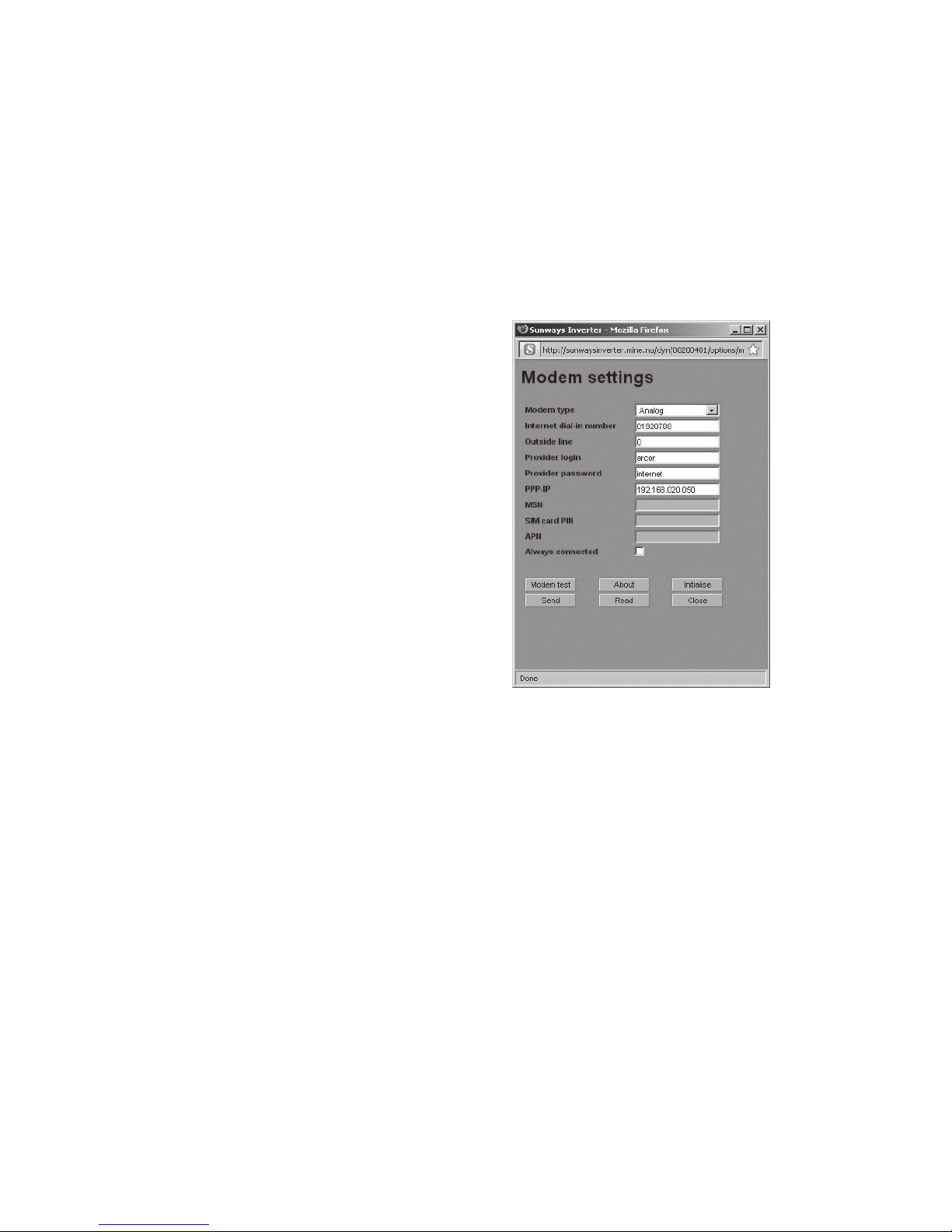
7 Sunways Browser
70
During the update process, update information is
displayed in the status indicator in the standard window of the Solar Inverter’s LCD display. The display
messages have the following meaning:
Display text Update type
Cnt. Upd. control software
Mon. Upd. monitoring software
Com Upd. communication software
Wif Upd. web interface
DWifUpd. dynamic web interface
MenSUpd. menu structure
MenEUpd. menu error texts
WifSUpd. web interface status texts
RWP.Upd. read/write parameters
ROP.Upd. read only parameters
ParaUpd. parameter update
Min Upd. update of the minute values in the
data logger files
Day Upd. update of the daily values in the
data logger files
Mon Upd. update of the monthly values in the
data logger files
YearUpd. update of the annual values in the
data logger files
SMinUpd. update of the minute values in the
system data logger files
SDayUpd. update of the daily values in the
system data logger files
SMONUpd. update of the monthly values in the
system data logger files
SYrUpd. update of the annual values in the
system data logger files
7.7 Internet dial-up via modem
Modem settings
If you use a modem to connect to the Internet, the
modem must be set up via the Sunways Browser.
First establish a connection between your PC and
the Solar Inverter (see section Direct Ethernet connection). Enter the following settings via «Settings
– Modem» in your web browser:
Modem type
Select the modem type:
analog, ISDN or GSM
Internet dial-in number
Dial-in number for your Internet provider (ISP)
Outside line
If you have a telephone system, you may have to
enter 0, for example. A comma results in a dialling
pause of 1 second
Provider login
User name defined by your Internet provider
Provider password
Password defined by your Internet provider
PPP-IP
You can reach the Solar Inverter by entering this IP
address in your web browser. The address is set to
192.168.20.50 by default.
Page 71
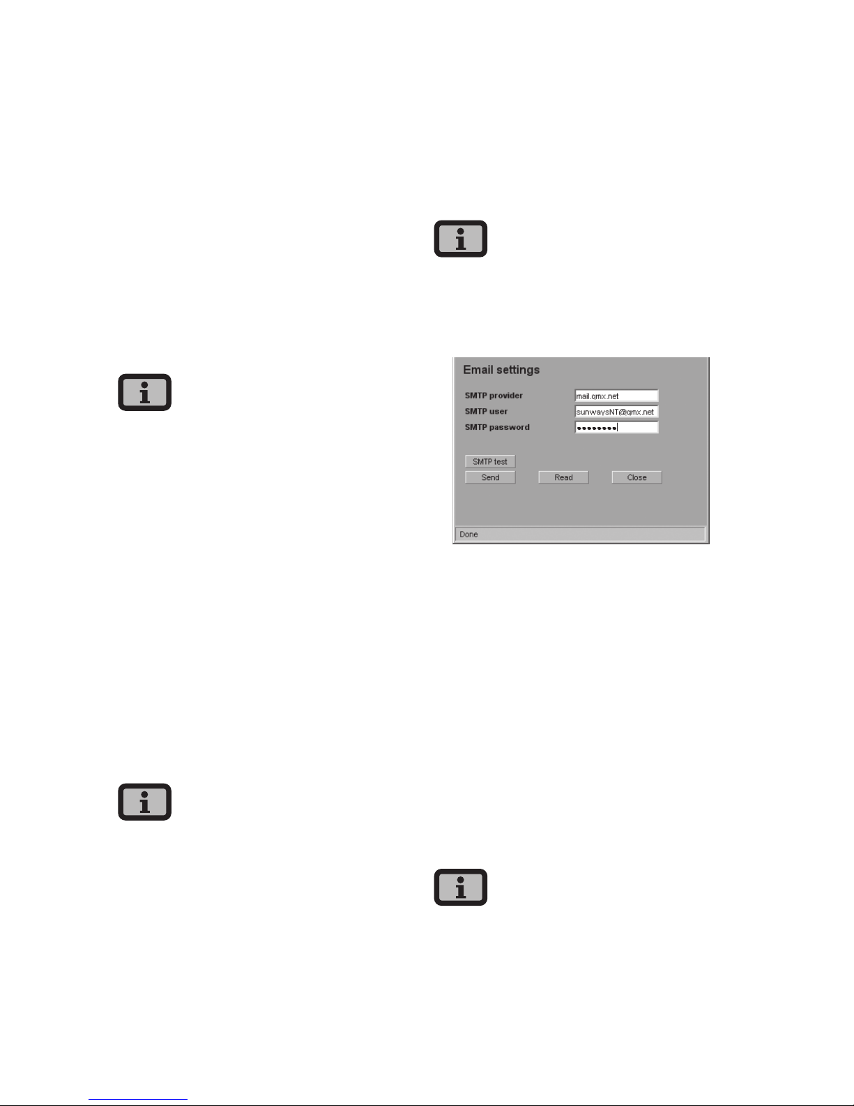
7 Sunways Browser
71
MSN
MSN for the modem extension (ISDN modem). This
is usually the extension number of without the area
code.
SIM card PIN
SIM card PIN for GSM modem.
APN
Access Point Number. You can obtain the APN from
your mobile communications provider.
Always connected
Select this option if you have a GPRS mobile tariff in
order to ensure that the device is always online.
Please note: With time-based tariffs (e.g. modem
connection with GSM or analog) this function can
result in very high telephone costs!
Function buttons
Click «Send» to save the settings in the Solar
Inverter.
Click «Read» to display the current Solar Inverter
settings.
Click «Modem Test» to test the connection between
the modem and the ISP. You receive a reply as to
whether dialling in was successful.
Click «Info» to obtain additional information about
the modem.
Click «Initialise» to re-initialise the modem.
· Before conducting the modem test, the settings
must be stored in the Solar Inverter by clicking
«Send».
· Cheap ISP dial-up numbers are available from
www.teltarif.de/internet or www.billiger-surfen.
de, for example. Here you will find not only tariff
information, but also the access data (phone
number, user name, password).
E-mail settings
To enable the Solar Inverter to send E-mails, the
E-mail settings must be stored via the Sunways
Browser. The settings can be accessed via «Settings –
Network» in the «Email Settings» section.
Requirements:
· When dialling in via modem, the correct dial-up
settings must be stored (see Internet dial-up via
modem).
SMTP provider
SMTP server for sending e-mails, e.g. mail.gmx.net
(max. 30 characters). Alternatively an IP address can
be entered.
SMTP user
User name for your e-mail provider (generally your
e-mail address), e.g. [email protected] (max. 50
characters)
SMTP password
Password for your e-mail provider
Function buttons
Via «SMTP Test» you can send a test e-mail to the
e-mail address stored for active alerting.
· Before conducting the SMTP test, the settings
must be stored in the Solar Inverter with «Send».
Page 72
7 Sunways Browser
72
· During the SMTP test an e-mail is sent to the
e-mail address stored in the monitoring system
(active alerting). Before starting the test check
whether a valid e-mail address is stored under
active alerting.
· If no login is set up on the configured SMTP
server, the password field must be left empty.
The login field is entered as the sender address
for the e-mail. If no login is specified, the Solar
Inverter sends the e-mail as
[email protected]
Click «Send» to save the settings in the Solar
Inverter.
Click «Read» to display the current Solar Inverter
settings.
7.8 Active alerting
General information
With active alerting you can receive status messages (errors and warnings) for your solar system
by e-mail. If a status message was active for longer
than 15 minutes or occurred 5 times in one day, you
will receive an e-mail at the next full hour under the
e-mail address stored in the Solar Inverter.
The master sends the status messages of all Solar
Inverters if they are CAN-networked.
Requirements:
· The master must be connected to the Internet via
a network or modem.
· When dialling in via modem, the correct dial-up
settings must be stored (see Internet dial-up via
modem).
· Correct e-mail settings must be stored in the
Sunways Browser (see «Email settings»).
Page 73
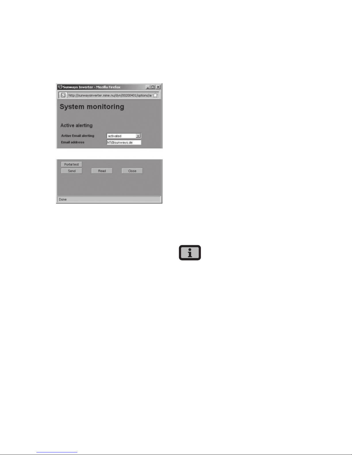
7 Sunways Browser
73
Alerting settings
The alerting settings can be accessed with the button «Settings – System Monitoring» in the «Active
Alerting» section».
Active Email alerting
Activation or deactivation of the active alerting
function.
Email address
In the «Email address» field enter the e-mail address
to which messages should be sent.
Function buttons
Click «Send» to save the settings in the Solar
Inverter.
Click «Read» to display the current Solar Inverter
settings.
7.9 Sunways Portal connection
General information
The operating data of your solar system can be
transferred to the Sunways Portal for remote monitoring via the Internet. This is possible without using
a Sunways Communicator.
The portal connection is configured via the Sunways
Browser. Following activation the master automatically sends a registration e-mail containing the
system data (e.g. number of devices, serial number,
etc.) to the Sunways Portal.
After activation the operating data are e-mailed
to the Sunways Portal on a daily basis before the
master is switched off for the night. Alternatively a
shorter interval can be selected. If a change is made
to your solar system (e.g. additional device), then
the change is automatically reported to the Sunways
Portal.
A basis access for the Sunways Portal for displaying
the yield data is available to every Sunways customer free of charge. Expanded functions, e.g. the
setpoint-actual comparison in the Sunways Portal,
can also be purchased for a fee.
The master sends the status messages of all Solar
Inverters if they are CAN-networked.
Requirements:
· The master must be connected to the Internet via
a network or modem.
· Correct Email settings must be stored in the Sunways Browser (see «Email settings»)
· Correct portal settings must be stored in the
Sunways Browser.
Page 74
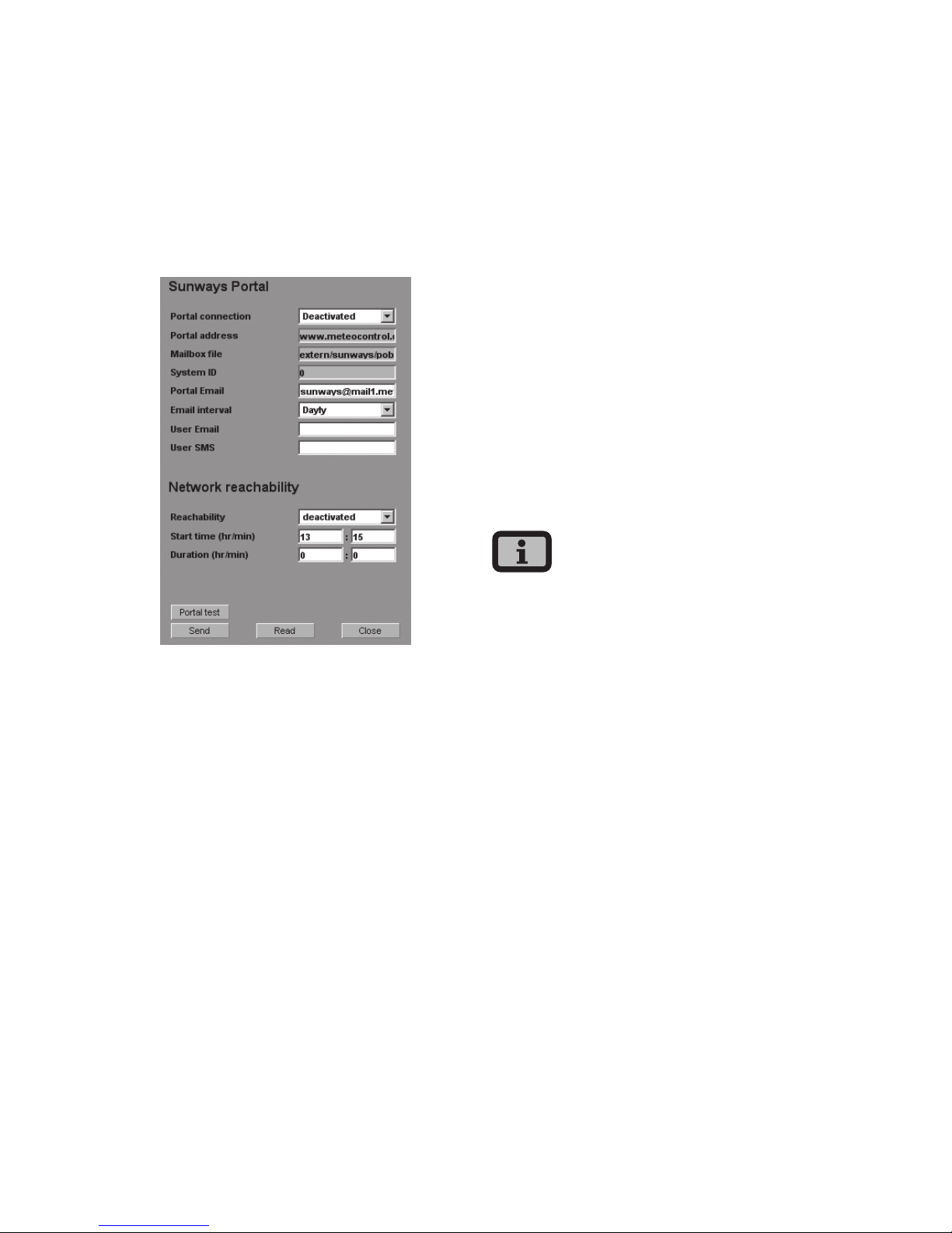
7 Sunways Browser
74
Setup
Check whether all requirements are met. Configure
the specified settings if necessary.
Open the settings page in the Sunways Browser. This
can be accessed under «Settings – System Monitoring» in the «Sunways Portal» section.
Portal connection
Activation or deactivation of the portal connection.
Portal address
Preset for the Sunways Portal
Mailbox file
Preset for the Sunways Portal
System ID
System ID assigned by the portal. This is generated
automatically after portal activation and sent to the
Solar Inverter. It can take up to 4 minutes before the
Solar Inverter displays the system ID.
Portal Email
Preset for the Sunways Portal. Alternatively you can
enter a different address if you wish to analyse the
operating data yourself.
Email interval
Select the e-mail interval. If you operate the system
on a DSL modem, you can set a short interval. If you
use a modem connection, select a longer interval
(e.g. daily) to avoid excessive telephone charges.
User Email
Enter an e-mail address for the confirmation e-mail
sent by the portal. It contains a link for activating
your system in the Sunways Portal.
User SMS
As an option you can specify an SMS number to
which an SMS message is sent after your system is
successfully set up in the portal.
Function buttons
With «Portal Test» you can test the portal connection. You receive an e-mail at the address specified
under «User e-mail» and an SMS if you have entered
your mobile phone number under «User SMS».
Before the portal test you must transmit the settings
to your Solar Inverter via «Send». If the test was successful, a message is sent to the user e-mail address
or the user SMS address.
Click «Send» to save the settings in the Solar
Inverter.
To view your system data in the Sunways Portal, you
require a user account. This will be issued to you if
you follow the link in the confirmation e-mail and
fill out the registration form.
Alternatively you can enter an existing user name
with the correct password to assign the system to an
existing user account.
Page 75
75
8 Appendix
8.1 Technical data
Model NT 2500 NT 3700 NT 4200 NT 5000
Article no. SI225NT0C SI237NT0C SI242NT0C SI250NT0C
DC Input
Rated DC power
Maximum DC current
Nominal DC voltage
MPP voltage range
Maximum voltage DC
Number of inputs per MPP tracker
Number of MPP trackers
2625 W 3885 W 4410 W 5250 W
7,5 A 11,0 A 13,0 A 18,0 A
340 V
340 V...750 V
900 V
2 x Tyco Solarlok
1
AC output
Rated AC output power
Maximum AC power
Nominal AC current
Maximum AC current
Nominal frequency
Frequency tolerance range
Grid voltage
AC voltage range
Distortion factor at Pn
Reactive power factor (cos phi)
Grid voltage monitoring
Earth fault protection
Insulation, frequency and DC current
monitoring
Required phases, number of grid
connections
Number of feed-in phases (230 V
single-phase)
2500 W 3700 W 4200 W 4600 W
2500 W 3700 W 4200 W 5000 W
10,9 A 16,1 A 18,3 A 21,7 A
12,0 A 17,8 A 20,2 A 24,0 A
50 Hz
47,5 Hz...50,2 Hz (according to DIN VDE 0126-1-1)
230 V
-20%...+15% (according to DIN VDE 0126-1-1)
< 2%
1 or adjustable from -0,9 to +0,9
single-phase (according to DIN VDE 0126-1-1)
RCD (according to DIN VDE 0126-1-1)
integrated according to DIN VDE 0126-1-1
1 (L, N, PE)
1
Performance
Stand-by consumption
Night-time consumption
Maximum efficiency
European efficiency
MPP efficiency (static)
Switching concept
4,0 W
< 0,1 W
97,8% 97,8% 97,8% 97,8%
97,4% 97,4% 97,3% 97,2%
> 99%
HERIC
®
/ FP topology, transformerless
Page 76

8 Appendix
76
Other
DC switch
Grid-connection fuse layout
Data interfaces
Sensor interfaces
Display
Plant supervision
IP degree of protection
according to IEC 60529
Max. relative humidity
Cooling
Ambient temperature
Overload behaviour
Dimensions (height x width x depth)
weight
Type of installation
Noise development
Standard warranty (option)
Certificates
internal
16 A 25 A 32 A 32 A
Ethernet, CAN, RS485, voltageless alarm relay,
S0 pulse output, modem
irradiation, temperature
LCD, backlit, 128 x 64 pixels
Active alarm via e-mail, Sunways Browser,
Sunways Communictor, Sunways Portal
IP 54
95%
free convection
-25°C...45°C (at full load)
working point adjustment
59 x 35 x 21 cm
26 kg
wall installation
< 35 dB (A)
5 years (10/15/20/25 years)
CE, DIN VDE 0126-1-1
Page 77
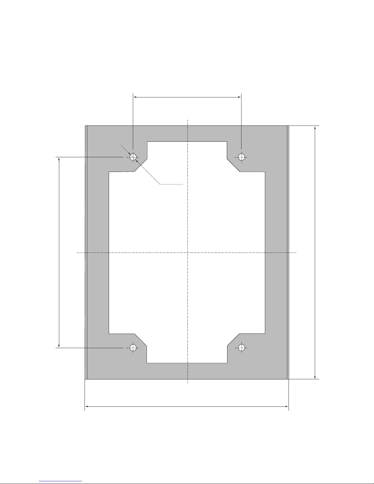
8 Appendix
77
8.2 Drilling template for wall bracket
You can use the following template to install the
wall bracket. All distances and measures are shown
on this drawing.
175
330
300
400
Ø 10
Page 78

8 Appendix
78
8.3 General liability disclaimer
Although information contained in this manual has
been checked with the greatest care for its accuracy
and completeness, not liability whatsoever can be
accepted for errors or omissions.
· Sunways AG reserves the right to change the
hardware and software features described here
at any time without prior notice.
· This manual may only be reproduced, passed
on, copied or translated into other languages in
whole or in part in any form or with any means
the prior written approval of Sunways AG.
· Sunways AG shall assume no guarantee for damage caused by faulty or lost data, due to incorrect operation or the malfunction of the Solar
Inverter, the software, additional devices or PCs.
All rights reserved. © Sunways AG
The products named on the cover page are protected by copyright and sold under licence. No part
of this document may be reproduced in any form
without prior written approval of Sunways AG and
the Sunways licensors.
Registered trademarks
The Sunways logo is a registered trademark of Sunways AG, Konstanz.
HERIC
®
is a registered trademark of Fraunhofer
Gesellschaft, Munich.
Page 79

79
C&F | Werbung und Dokumentation, Villingen-Schwenningen · www.cundf.de
Page 80

8 Appendix
80
Sunways AG
Photovoltaic Technology
Macairestraße 3 - 5
D - 78467 Konstanz
Telefon +49 (0)7531 996 77-0
Fax +49 (0)7531 996 77-444
E-Mail [email protected]
www.sunways.de
Technische Hotline +49 (0)7531 996 77-577
SD130812A 09/10 EN
 Loading...