

Page 1
User Manual for
Sunways Solar Inverter
AT 5000, AT 4500, AT 3600, AT 2700
Page 2
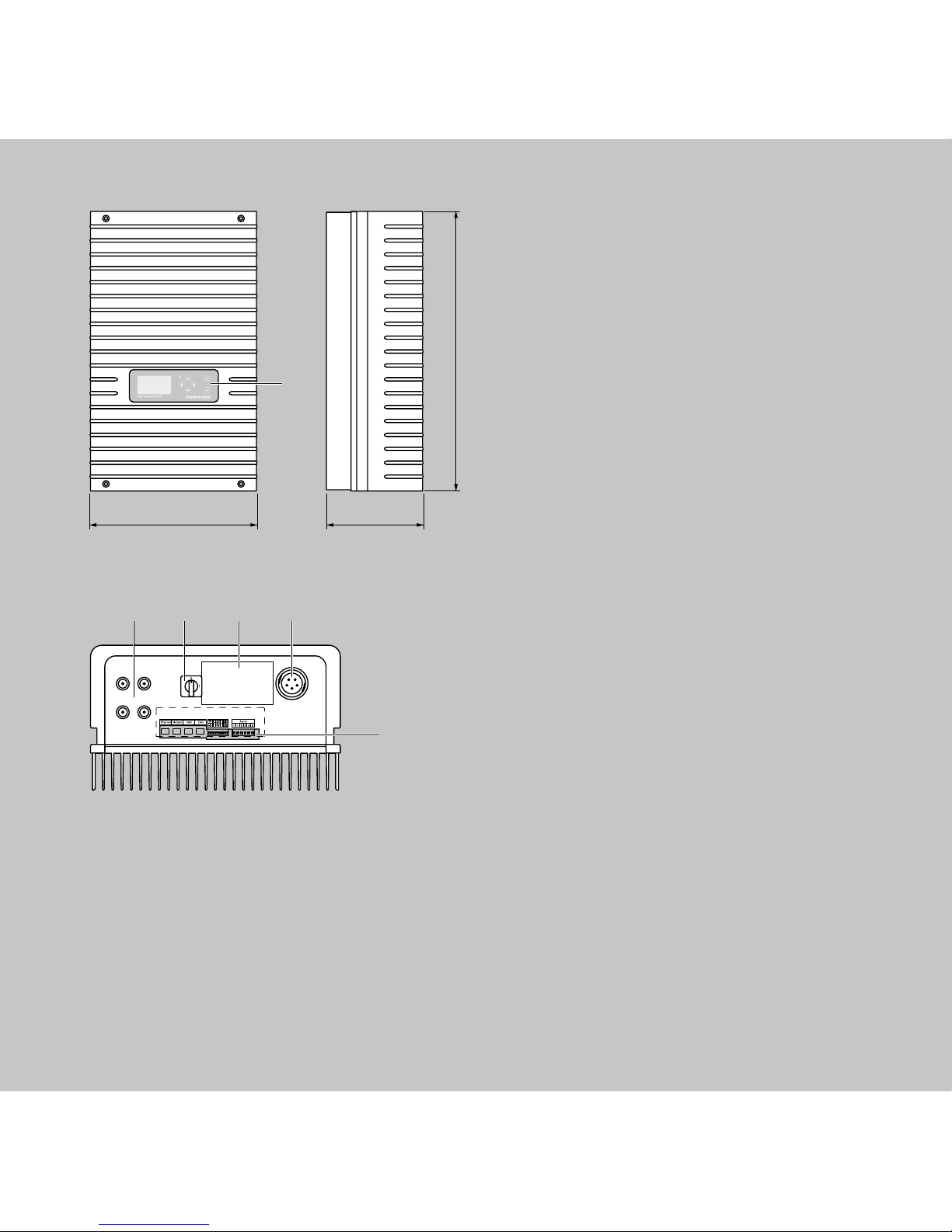
1 Operating field with LCD display, oper-
ating LED and keyboard
2 DC connections
3 DC load break switch
4 Rating plate
5 AC connection
6 Communication interfaces
350
585
205
+–
+–
1
2
2
3 4 5
6
1
Page 3

3
This user manual contains explanations
on using the Sunways Solar Inverter. You
will learn to recognise the many possibili
ties of the solar inverter. Information is
provided on safety, installation, com
missioning, operation and system
monitoring.
Please observe the safety precautions
exactly to ensure increased safety at the
operating site of the solar inverter.
Introduction
Thank you for deciding in favour of a
Sunways Solar Inverter of the AT Series!
In doing so you have purchased an inno
vative, high-quality product with unique
equipment features and a high, constant
efficiency. This solar inverter is equipped
with HERIC
®
topology and innovative FP
switching, and therefore enables opera
tion on a large number of silicon and
thin-film modules – as accustomed from
Sunways – without the use of a trans
-
former.
Page 4

4
Imprint
All rights reserved.
© Copyright by:
Sunways AG
Photovoltaic Technology
Macairestraße 3 - 5
78467 Konstanz
Germany
This user manual may only be reprinted or copied in whole
or in part with the express, written approval of Sunways
AG. Any type of reproduction, distribution or storage on
data carriers in any form and of any kind not authorised
by Sunways AG represents a violation of the applicable
copyright laws and will be prosecuted. We reserve the right
to make technical changes which serve to improve the
unit, or which increase the safety standard – even without
separate prior notice.
Publisher responsible for the content: Sunways AG
This user manual contains products and product names
which are registered trademarks. The mention of products
and product names is used only for information purposes
and does not represent
product misuse. The passage referring to these products in
this user manual does not represent original documenta
tion of the respective product.
Page 5

5
Content
Introduction 3
1.0 Product Description
8
1.1 Proper use 9
1.2 Function description
9
Block diagram 11
1.3 Integration in solar system 12
Design of solar generator 12
Standard components of a solar
system 1
3
1.4 Assembly description 14
1.5 Delivery scope 1
5
2.0 Safety precautions 16
2.1 General safety precautions 17
2.2 Explanation of symbols and
warnings 1
8
Warnings and symbols in user
manual 1
8
Symbols 1
9
2.3 Basic safety measures 20
2.4 Safety concept 2
0
3.0 Installation 22
3.1 Mechanical installation 23
Requirements for installation
location 2
3
Installation 2
5
3.2 Electrical installation 26
Solar generator connection 26
Grid connection 3
3
3.3 Installing communication 39
Interface overview 39
Networking solar inverters via
CAN bus 4
0
Networking solar inverters via
RS485 interface 4
1
S0 interface 4
2
Connection of temperature and
irradiation sensor 4
3
Connecting alarm relay 4
4
4.0 Commissioning 4
6
4.1 Connecting and disconnecting
solar inverter 4
7
Connecting 47
Switching off 4
8
Page 6

6
4.2 Commissioning 49
Commissioning single unit 50
Commissioning several
networked units 5
2
Later commissioning 5
5
5.0 Operation 5
6
5.1 Operating elements 57
Operating field 57
LCD display 5
7
Operating LED 5
8
Standard screen (single unit) 5
9
Standard screen (system) 6
0
5.2 Access rights 61
5.3 Menu structure 6
2
Instantaneous Values – Unit 63
5.4 Overview of screen displays 63
Events – Unit 64
History – Unit 6
5
Information – Unit 6
6
Instantaneous values – Solar
system 6
7
Yields – Solar system 6
7
Events – Solar system 6
8
History – Solar system 6
8
System info – Solar system 6
9
Settings – General 7
0
Settings – Login 7
1
Settings – Network 7
2
5.4 Malfunction displays 73
6.0 System monitoring 96
6.1 General information 97
6.2 Integrated data logger 9
8
6.3 Direct Ethernet connection 9
9
6.4 Network settings on solar
inverter 10
0
6.5 Network settings on PC 10
1
6.6 Connection via an existing
Ethernet network 10
5
6.7 Connection via Internet 10
7
6.8 Connection via Sunways
Modem 10
8
6.9 Dialling in from a PC to solar
inverter 10
9
6.10 Sunways Browser 11
4
General information 114
Access protection 11
5
Overview – Menu 11
6
Language selection 11
6
Page 7

7
Setting date/time 117
Software update 11
8
Distributing software update
to networked units 11
9
6.11 Internet dial-in via modem 120
Modem settings 120
Email settings 12
2
6.12 Active alerting 124
General information 124
Alerting settings 12
5
6.13 Sunways portal connection 126
General information 126
Setup 12
7
7.0 Appendix 13
0
7.1 Technical data 131
7.4 General liability disclaimer 13
9
Page 8

8
1.0 Product Description
Page 9

9
1.1 Proper use
The Sunways AT Solar Inverter is the link
between your solar generator and the
public power grid. The energy from the
connected solar generator is converted to
grid-conformant AC current and fed into
the grid.
Thanks to the HERIC
®
topology with FP
switching, the AT Solar Inverter has a
voltage curve which corresponds to that
of a transformer unit with an earthed
negative terminal, and is generally also
recognized for operation on thin-film
modules.
Solar modules which require earthing of
the positive terminal cannot be operated
with the AT Solar Inverter. If in doubt,
always ask your module manufacturer
about a release!
1.2 Function description
Conversion from direct into alternating
current
The AT Solar Inverter converts the direct
current produced by the solar generator
into alternating current. The alternating
current is then fed into the public power
grid.
Operating and display elements
Various interfaces are available for sys
-
tem configuration and monitoring:
· Operating field (LCD display and key
board) for displaying operating and
status values or for inputting system
parameters
· Operating LED
· Integrated web server for display and
configuration via a web browser
Interfaces
· Bus interface for connecting an
analogue modem, ISDN modem or
GSM/GPRS modem
· Ethernet interface for connecting a PC
or for integration in existing networks
Page 10

10
· CAN bus interface for interconnecting
several solar inverters
· S0 pulse output for controlling large
displays
· Alarm relay for realising simple moni
-
toring locally
· Interface for connecting an irradiation
and temperature sensor
Data logging
The AT Solar Inverter is equipped with
internal data logging for recording and
saving system data:
· 5-minute mean values of voltages,
currents, output, temperature and ir
-
radiation (if sensor is installed)
· 5-minute, daily, monthly and annual
values of energy yield
· Memory for malfunction messages
Grid monitoring
The AT Solar Inverter assumes the task
of grid monitoring for the protection of
the unit and persons. In case of abnormal
grid conditions, feeding is immediately
interrupted and the solar inverter discon
nects from the grid by triggering the grid
relay.
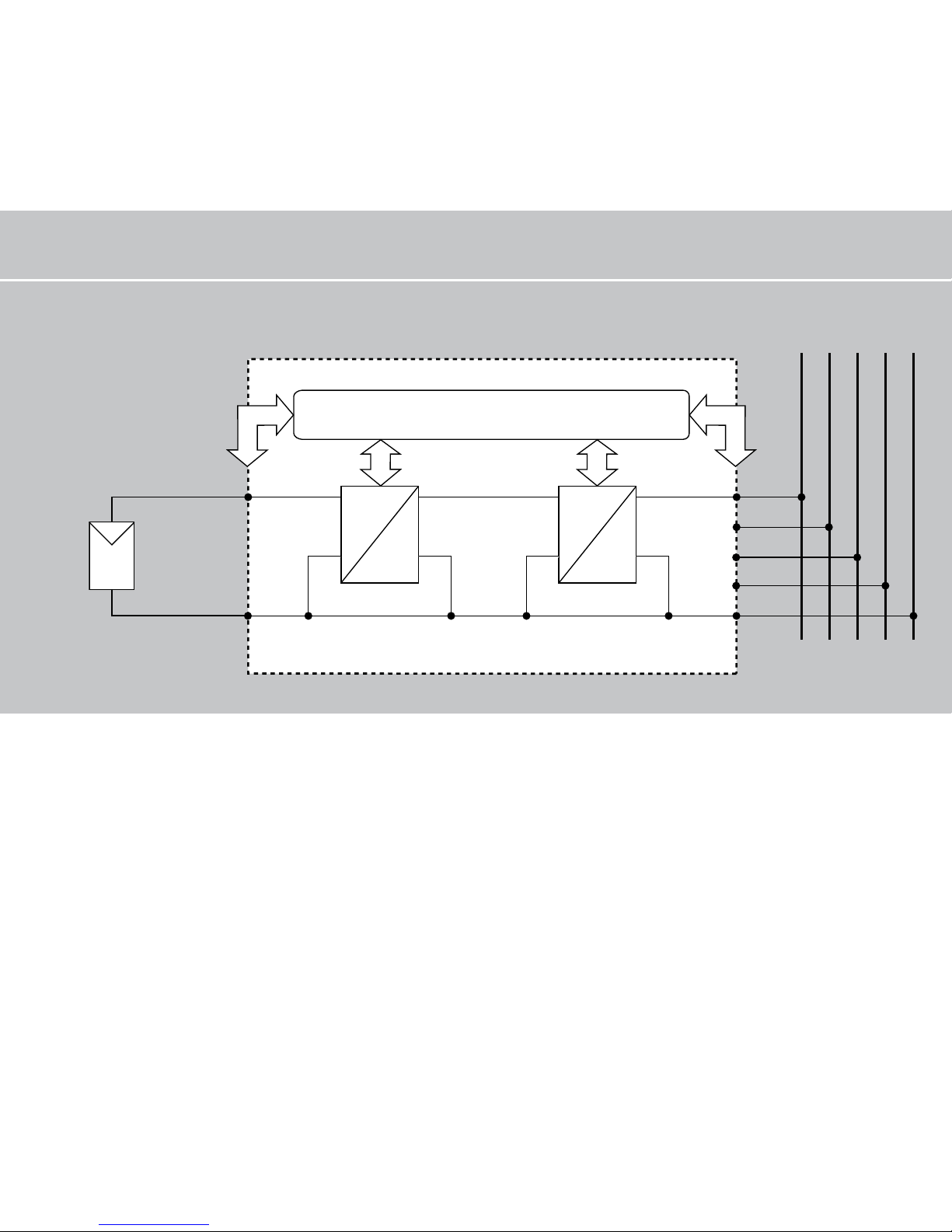
Design of solar inverter
The principle design of the AT Solar In
verters can be recognised from the block
diagram. The most important character
istic of the inverter is the earthing of the
solar generator, i.e. the negative terminal
is directly connected to the neutral con
ductor on the grid.
The solar generator voltage connected to
the inverter input is always positive and is
initially adapted by the DC actuator and
then converted to alternating current by
the high-efficiency HERIC
®
inverter. The
AC connection is made with 5 wires for a
3-phase feed point (3-phase AC current
connection) due to the 3-phase passive
grid monitoring, whereby feeding is
only single-phase. A 3-wire connection
is made at the single-phase feed point
(alternating current connection).
Page 11
11
Block diagram
=
=
=
~
L1
L2
L3
PE
N
L1 L2 L3 PE N
–
+
DC+
DC–
Control and monitoring
DC actuator
HERIC® inverter
Solar generator
Grid
Page 12

12
1.3 Integration in solar system
Design of solar generator
The technical data of the selected solar
generator must be within the solar
inverter‘s specifications (see Technical
Data). Incorrect dimensioning can lead to
reductions in the yield and to destruction
of the unit.
The Sunways design program Sundim
may be helpful to you. Sunways Sundim
is available on the included CD-ROM or
at our homepage www.sunways.de.
Be sure to take the following points into
account before planning your system:
· Watch the celestial alignment of the
modules. A maximum yield is achieved
in Central Europe with a module slope
of 30° to the vertical and direction of
the solar generator field directly to the
south.
· The output of the cells decreases as
the module temperature increases.
Install your solar generator with suf
-
ficient ventilation from behind.
· Check your solar generator approx.
every three years for soiling. This oc
curs especially on the lower edge of
the modules and forms a veil that can
not be washed off even by heavy rain.
Reduced yield can be prevented by
cleaning with a wet cloth or a brush.
· Avoid switching off individual modules
or solar cells of your system. This can
lead to major decreases in yield.
Page 13

13
Standard components of a solar system
Depending on the recommendations of
your PV planning expert, your PV system
consists of the following components:
1 Solar generator
2 Solar inverter with integrated DC load
break switch
3 Mains fuse and energy meter
Options
4 Irradiation sensor with integrated
temperature sensor
5 PC for monitoring system
6 Large display
Standard components
1
4
5
2
3
6
DC
AC
Page 14
14
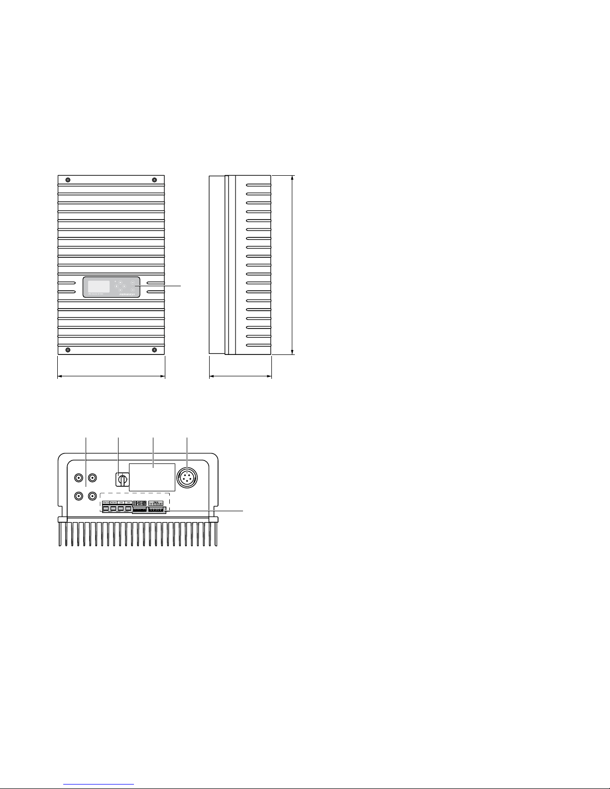
1 Operating field with LCD display,
operating LED and keyboard
2 DC connections
3 DC load break switch
4 Rating plate
5 AC connection
6 Communication interfaces
350
585
205
+–
+–
1
2
2
3 4 5
6
1
1.4 Assembly description
Page 15

15
1.5 Delivery scope
The delivery consists of:
· Sunways Solar Inverter of the AT-Series
· Installation frame
· 2 pairs of Tyco Solarlok plug-in connec
-
tors
· AC connector
· CAN terminating resistor connector
(connected)
· Ethernet cable, 2 m (CAT 5e, 1:1)
· Manual
· Warranty card
· CD-ROM, including: Sunways Sundim
design program, product and service
information
Checking delivery
Before shipment our products are
checked for proper condition. Despite
careful, recyclable packing, transport
damage may occur, for which the trans
-
port company is generally responsible.
Please check the delivered solar inverter
thoroughly!
Should you discover damage to the pack
ing or the solar inverter, please inform
the transport company immediately. Your
specialist dealer will be happy to sup
port you if necessary. A possible damage
report must always be received by the
transport company in writing at the latest seven days after receipt of the goods.
Page 16

16
2.0 Safety precautions
Page 17

17
2.1 General safety precautions
Observe information in operating
manual!
The condition for the safe handling and
malfunction-free operation of the AT
Solar Inverter is a knowledge of the basic
safety precautions.
This user manual contains the most
important information on operating the
system safely.
Each person concerned with the instal
lation, commissioning, maintenance and
operation of the solar inverter must have
read and understood the entire user
manual, and in particular the chapter
entitled Safety Precautions.
In addition, the rules and regulations for
accident prevention applicable for the
operating site/plant must be observed.
Dangers when handling the AT Solar
Inverter
The solar inverter has been built in ac
cordance with the latest rules of technology and the recognized safety rules and
may only be used
· for its intended use
· when in proper condition with regard
to safety.
Improper use may lead to dangers to the
life and limb of the user or others, or
can adversely affect the system or other
property.
In case of malfunctions which can impair
safety, the system must be shut down
immediately and secured against being
switched on again. The malfunction must
then be eliminated immediately.
Page 18
18
Warranty and liability
The „General Terms and Conditions of
Sale and Delivery“ of Sunways AG always
apply. Warranty and liability claims for
injuries and damage shall not be accept
ed if they are due to one or more of the
following causes:
· Improper use of the solar inverter
· Improper installation, commissioning,
operation and maintenance
· Operation of the solar inverter with
defective and/or non-operational
safety and protective equipment
· Failure to observe the information in
the user manual regarding installa
tion, commissioning, operation and
maintenance
· Unauthorised constructional
modifications
· Insufficient monitoring of wearing
parts
· Improperly conducted repairs
· Catastrophes resulting from the effects
of foreign bodies and acts of God.
2.2 Explanation of symbols and
warnings
To help you quickly understand this
manual and safely use the solar inverter,
the following warnings and symbols are
used.
Warnings and symbols in user manual
!
DANGER
This symbol indicates an immediate
danger which will result in death, injury
or serious damage if the applicable safety
regulations are not followed.
!
CAUTION
This symbol indicates an immediate
danger which can result in damage if
the applicable safety regulations are not
followed.
Page 19
19
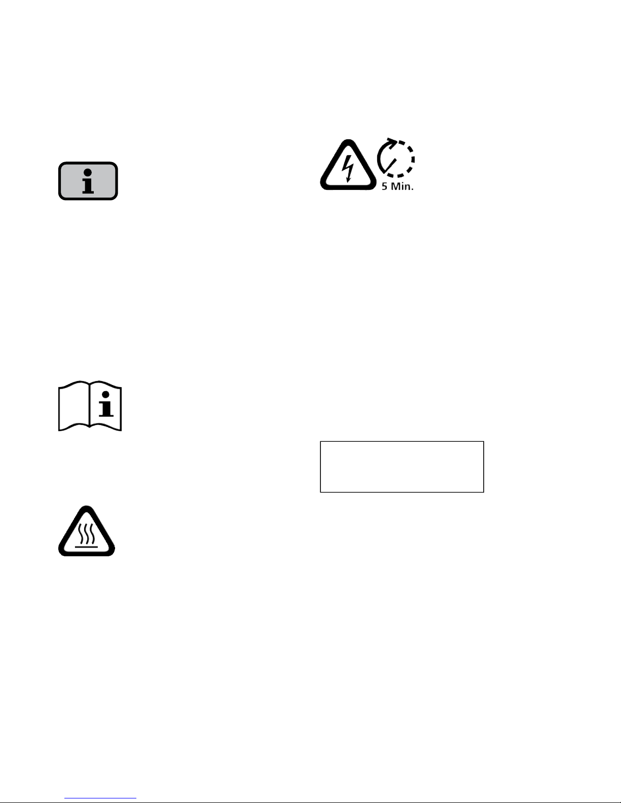
Symbols
Information
This symbol indicates important informa
-
tion which contributes to a better under
-
standing of the solar inverter.
Warnings and symbols on unit
The following warnings on the housing
of the solar inverter point out dangers.
Always observe the warnings exactly!
This symbol indicates that the user man
ual must be read and understood before
putting the unit into operation.
IMPORTANT
Hot surface! The housing can heat up
during operation.
The unit must be disconnected for the
mains supply and from the PV generator
before opening the housing. The unit
still carries life-threatening voltage for
approx. five minutes internally and at the
connection sockets of the PV generator
following disconnection from the PV gen
erator. The energy storage capacitors are
not completely discharged until after this
time. You must wait at least five minutes
after disconnecting the unit from the
mains supply and from the PV generator
before opening the unit.
Warning!
High leakage current,
earth connection essential before
connecting supply.
WARNING!
High leakage currents. Be sure to make
an earthing connection before connect
-
ing the power supply circuit (AC system)!
Page 20

20
2.3 Basic safety measures
Electrical work on the solar inverter must
be conducted by a qualified electrician
while observing the VDE regulations,
national and other regulations!
The solar inverter may only be opened
by persons authorised by Sunways AG to
do so!
When circuit breakers are tripped, the
fault cause must be determined and
eliminated before returning the unit to
operation.
Check electrical equipment regularly!
Retighten loose connections!
Replace damaged lines/cables
immediately!
2.4 Safety concept
The following parameters are monitored
and displayed continuously and simulta
-
neously by the inverter controller:
· DC overvoltage
· Overvoltage L1 > 10%
· Overvoltage L1 > 15%
· Undervoltage L1
· Overvoltage L2
· Undervoltage L2
· Overvoltage L3
· Undervoltage L3
· Isolated operation
· Overfrequency L1
· Underfrequency L1
· Surge error (brief overvoltage L1)
· DC share in AC current
· AFI residual current jump > 30 mA
· AFI residual current > 300 mA
· Overtemperature of heat sink
Page 21

21
When a malfunction occurs, feeding is
immediately interrupted and the solar
inverter disconnects from the grid by
triggering the grid relay.
The potential-free alarm relay is switched
(except for grid undervoltage L1).
In addition, the following protective
equipment in accordance with overvolt
age category III is provided on the grid
and on the solar generator side:
· Grid-side varistors
These protect the power semiconduc
tors in case of high-energy, short-term
voltage peaks in the grid and provide
for an energy reduction in reactor in
case of a grid disconnection.
· Generator-side varistors
Varistors offer protection against at
mospheric overvoltages (e.g. caused by
remote strikes during thunderstorms).
Page 22

22
3.0 Installation
Page 23
23
3.1 Mechanical installation
Requirements for installation location
!
DANGER
The solar inverter may not be installed in
rooms subject to explosion hazards.
The solar inverter may not be exposed to
caustic gases!
No combustible or highly flammable
materials may be stored within 3 metres
of the solar inverter.
Mechanical load-bearing capacity
Note during installation that the solar
inverter weighs 30 kg. The installation
surface must be firm and able to carry
this weight in the long term.
Thermal interaction
The installation surface must consist of
flame-retardant material (not suitable:
surface of wood or plastic; suitable: con
crete and masonry), as the frame of the
solar inverter can heat up to a maximum
of 70°C.
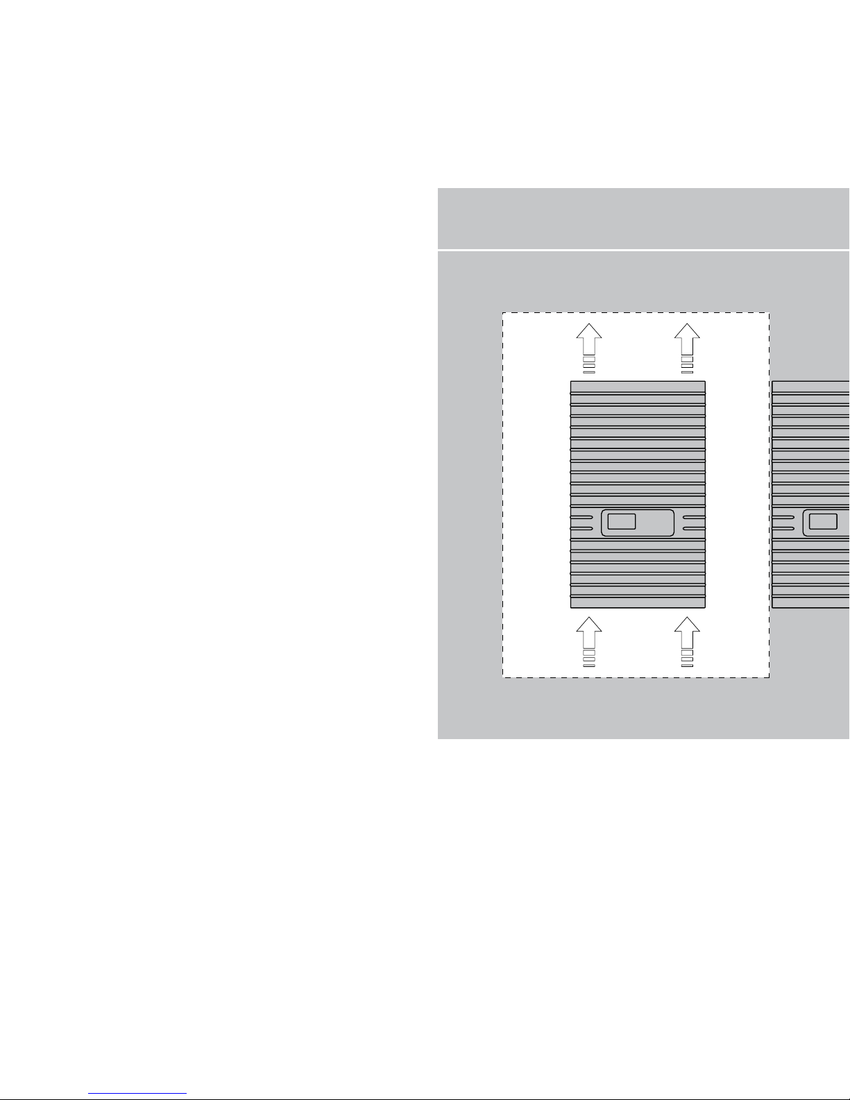
A minimum distance of 300 mm to other
units, cabinets, ceilings, cable ducts,
etc. must be maintained above, below
and to the sides of the housing.
See the figure Requirements for installa
tion location.
The solar inverter must be installed verti
-
cally to enable sufficiently free convec
-
tion.
Several solar inverters may not be mount
ed over each other to prevent them from
heating each other.
Page 24
24
Ensure sufficient heat dissipation when
installing the solar inverter in a switch
cabinet or closed room.
The ambient temperature may not drop
below or exceed -25°C and +40°C respec
tively. At ambient temperatures above
40°C, the inverter automatically reduces
its output.
The solar inverter should not be exposed
to direct sunlight to protect it from un
-
necessary external warming.
Protection against moisture and foreign
bodies
The high protection type IP54 allows in
-
stallation indoors and in roof-covered ar
eas outdoors, however the solar inverter
may not be directly exposed to rain.
Requirements for installation location
300 mm
300 mm
300 mm
300 mm
Wall
Ceiling
Cold
air
Hot
air
Page 25
25
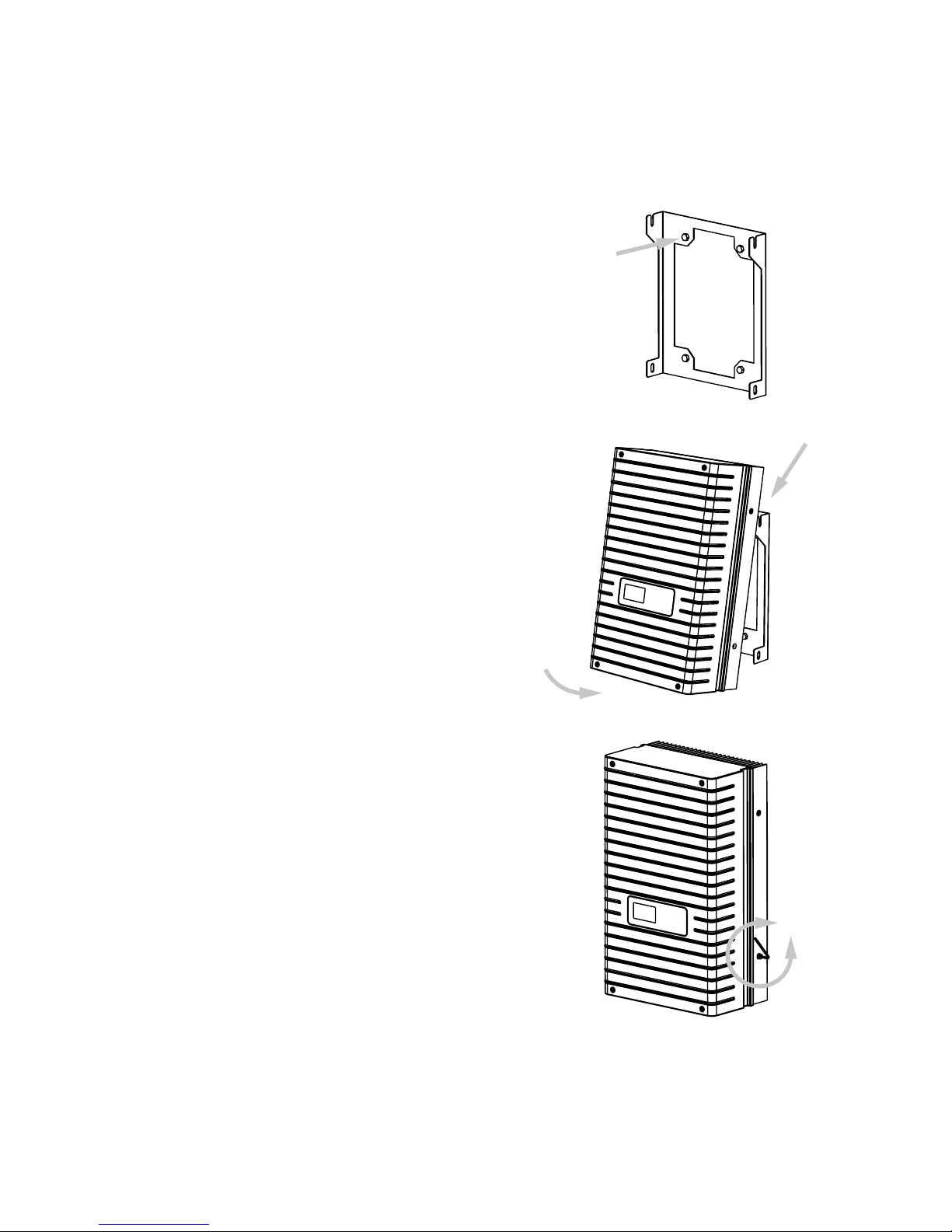
Installation
Proceed as follows to install the solar
inverter:
1. Hold the wall bracket at the point at
which you want to attach the solar
inverter and mark the mounting holes.
2. Drill the holes with a 10 mm dia. drill
bit.
3. Install the wall bracket with corre
-
sponding screws and dowels depend
-
ing on the surface condition.
4. Unscrew the locking screw of the solar
inverter at the lower left with an Allen
key
5. Hook the solar inverter into the cut-
outs of the installation frame at the
top on both sides.
6. Secure the solar inverter by tightening
the locking screw.
Page 26
26
3.2 Electrical installation
Solar generator connection
!
Extreme danger from electric shock!
Touching live parts can result in death.
All electrical work must be conducted by
a qualified electrician while observing
the VDE regulations, national and other
regulations!
Execute the direct current wiring in ac
cordance with the system dimensioning
of your planning expert.
Prepare all solar generator cables before
you carry out the connection of the solar
generator to the solar inverter.
Check each solar generator string for
proper operation with an open-circuit
voltage and short-circuit current measurement.
Check using the rating plate on the solar
inverter whether it is approved for the
maximum solar generator voltage.
The positive and negative lines must be
kept electrically separate from the earth
potential.
Touchable, live parts of the solar genera
tor (e.g. metal frame, carrying structure,
etc.) must be earthed (connection with
PE).
Check the solar generator against shortcircuits to earth.
Before connecting the solar generator to
the solar inverter, the integrated DC load
break switch must be opened quickly
(position 0).
After the PV solar generator is connected
to the solar inverter and the DC load
break switch is switched on, the direct
generator voltage is present internally.
The connectors may not be separated
while under load.
Page 27
27
Always separate the solar generator
side first by quickly opening the DC load
break switch and then the grid connec
tion by switching off the corresponding
mains fuse.
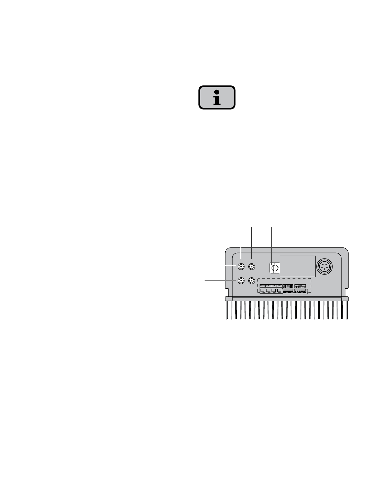
Survey
The solar generator can be directly con
nected to the solar inverter with two
strings. The connection is made via the
shockproof Tyco Solarlok plug-in connec
-
tion system accessible from outside.
The solar inverter has two electrically
connected DC inputs, which are arranged
in pairs on the underside.
The solar generator strings must be iden
tically dimensioned and comply with the
specifications of the solar inverter.
No external DC load break switch is
required. A DC load break switch as re
quired in accordance with DIN VDE 0100712 is integrated in the solar inverter.
+–
+–
1
2
3– +
1 Connection of solar generator string 1
2 Connection of solar generator string 2
3 DC load break switch
Page 28
28
Tyco Solarlok plug-in connection system
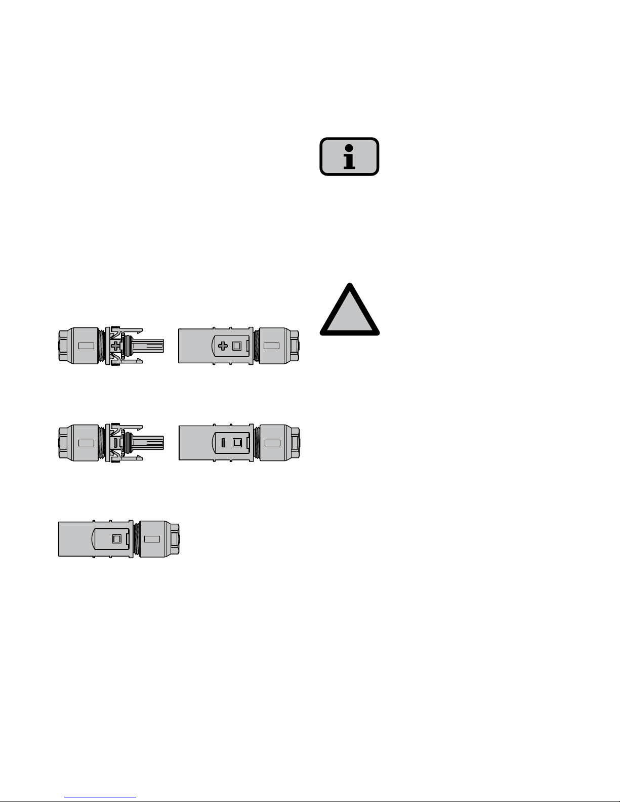
The Solarlok plug-in connection system is
used for the simple, reliable connection
of individual solar generators up to the
solar inverter.
Components
The following connectors are used:
· Positively coded connector
· Negatively coded connector
· Neutral connector
The neutral connector can be used to
connect both positively and negatively
coded sockets.
Installation
!
Extreme danger from electric shock!
Touching live parts can result in death.
All electrical work must be conducted by
a qualified electrician while observing
the VDE regulations, national and other
regulations!
Tyco Solarlok connectors are only reliable
for connection on permanently installed
lines.
Only the Tyco-Solarlok hand crimping pli
-
ers may be used to crimp the connectors.
Page 29
29
During preassembly, the connectors must
be separated from all other voltage
sources.
The connectors may not be separated
while under load. The circuit must be
opened at a suitable point for this pur
-
pose.
Provide the lines with corresponding
stickers as close as possible to the connec
-
tors to prevent confusion.
Any kind of soiling (dust, moisture, etc.)
has a negative effect on the connector
system with regard to function over the
intended period of use. This particularly
applies to the suitability for use of the
seals and the crimping of the contacts.
Therefore, extreme care must be taken
to achieve proper processing during as
-
sembly.
Various circular contacts are used for
different conductor cross-sections with
the Tyco Solarlok connectors. The correct
tool insert must be used in accordance
with this cross-section. The included Tyco
Solarlok connectors are equipped with
circular contacts for a cable cross-section
of 4 mm² to 6 mm².
The seals and clamping baskets used in
the preassembled connectors are ap
-
proved for cable sheath diameters from
4.5 mm to 6.9 mm. Special seals and
clamping baskets must be used for cables
with a sheath diameter greater than
6.9 mm.
The Tyco Solarlok hand crimping pliers
can be purchased from your sales partner.
Page 30
30
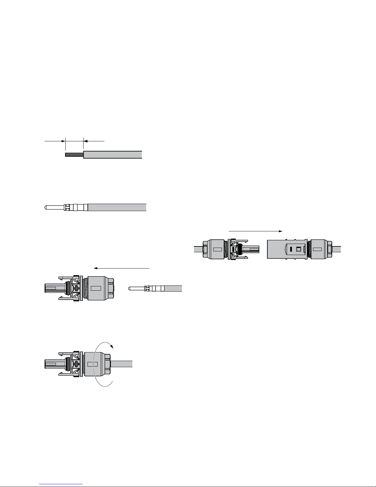
The following sequence must be observed during assembly:
1. Stripping the voltage-free line.
8
2. Crimping on the circular contact with
the Tyco Solarlok hand crimping pliers.
3. Sliding the cable gland onto the line
and engaging the contact in the
connector housing.
4. Tightening the cable gland with
1.5 Nm.
Handling
The positively/negatively coded connec
tors are marked with polarity symbols
and a coloured ring (blue = negative,
red = positive). They are equipped with
coding ribs for assignment, which ensures
that only connectors of the same polarity
can be connected to each other.
Connecting socket and plug. The system
is only correctly locked if the locking
hooks are recessed flush in the mating
piece.
Page 31
31
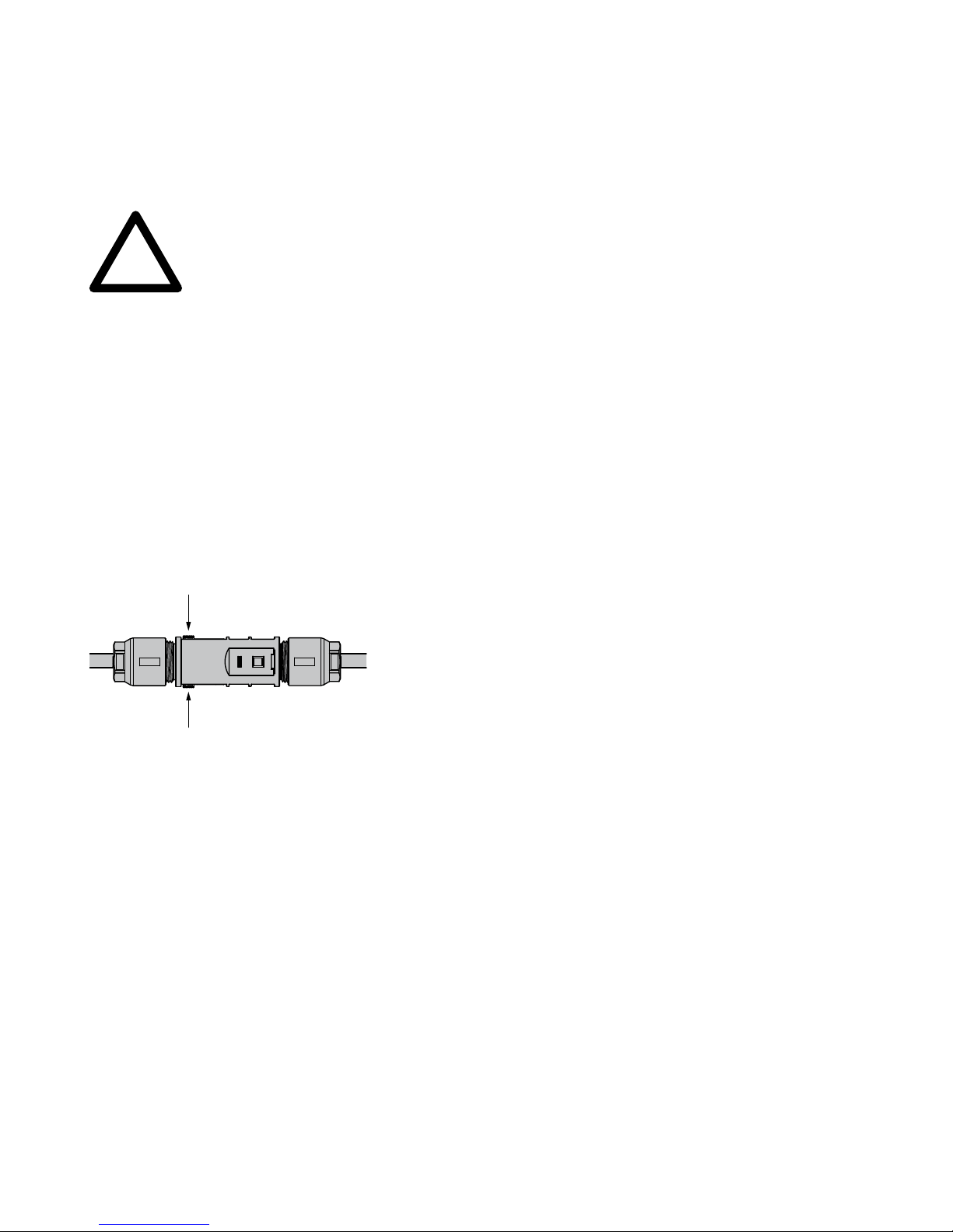
!
CAUTION
The connectors may not be separated
while under load. The circuit must be
opened at a suitable point for this pur
-
pose.
Release the locking device by pressing
on the ribbing of the locking hooks and
pulling them apart.
Page 32
32
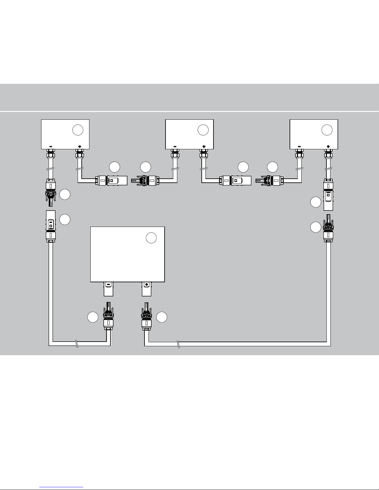
Connection example
1 Solar module box
2 Negatively coded socket
3 Negatively coded plug
4 Positively coded socket
5 Neutral connector
6 Solar inverter
2
3
5
4
5 2 5 2
2 4
1 1 1
6
– –NN
N
+
–
–
+–
Page 33
33
Grid connection
!
Extreme danger from electric shock!
Touching live parts can result in death.
All electrical work must be conducted by
a qualified electrician while observing
the VDE regulations, national and other
regulations!
Observe the pin assignment of the AC
bayonet connector. An incorrect assign
-
ment can result in the unit being de
-
stroyed.
No consumers may be connected to the
supply line from the solar inverter to the
mains fuse.
Always separate the solar generator
side first by quickly opening the DC load
break switch and then the grid connec
tion by switching off the corresponding
mains fuse.
If the voltage on the AC connection ex
ceeds the permissible value due to a long
line length or an insufficient cable crosssection, the solar inverter will discon
nected from the grid. In power grids with
a low output and a high solar generator
output, this can lead to individual solar
inverters being switched off and then on
again several times.
Survey
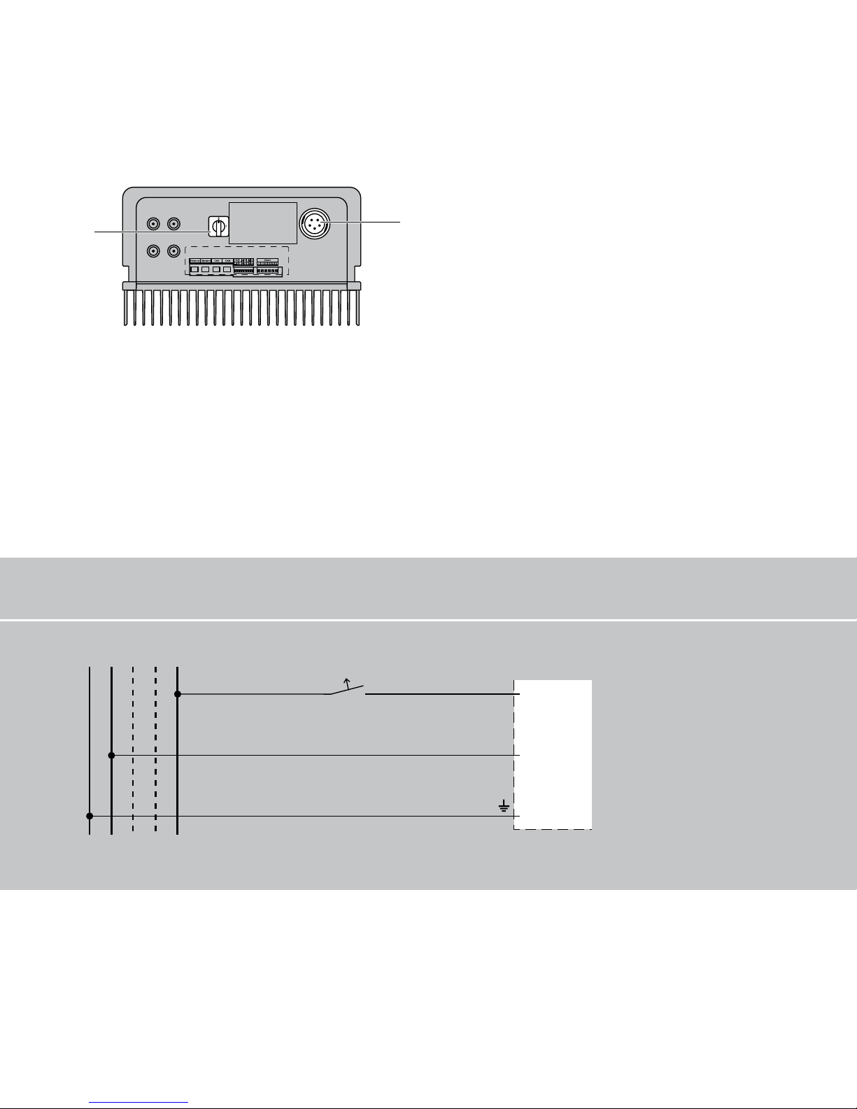
The grid connection of the solar inverter
is made via an AC bayonet connector on
the underside of the unit. With a 3-phase
feed point (3-phase AC connection), a 5wire connection (L1, L2, L3, N, PE) is used
due to the 3-phase passive grid monitor
ing, while only a 3-wire connection (L1,
N, PE) is used on the single-phase feed
point. Feeding is always single-phase via
AC terminal 2.
Page 34
34
+–
+–
1
2
1 DC load break switch
2 AC connection
Terminal diagram
PE N L3 L2 L1
1
2
INVERTER
Mains fuse
A corresponding circuit breaker is recom
mended as a line protection element in
the grid feed direction:
AT 2700: 3 x 16 A
AT 3600: 3 x 25 A
AT 4500: 3 x 25 A
AT 5000: 3 x 32 A
with slow-blow characteristic C
A three-pin circuit breaker in individual
fuses can be used.
3-phase AC grid
Page 35
35
Depending on the grid operator and
the feed point, a three-phase meter or a
single-phase meter must be used.
Some grid operators require the use of a
reverse-current-capable meter.
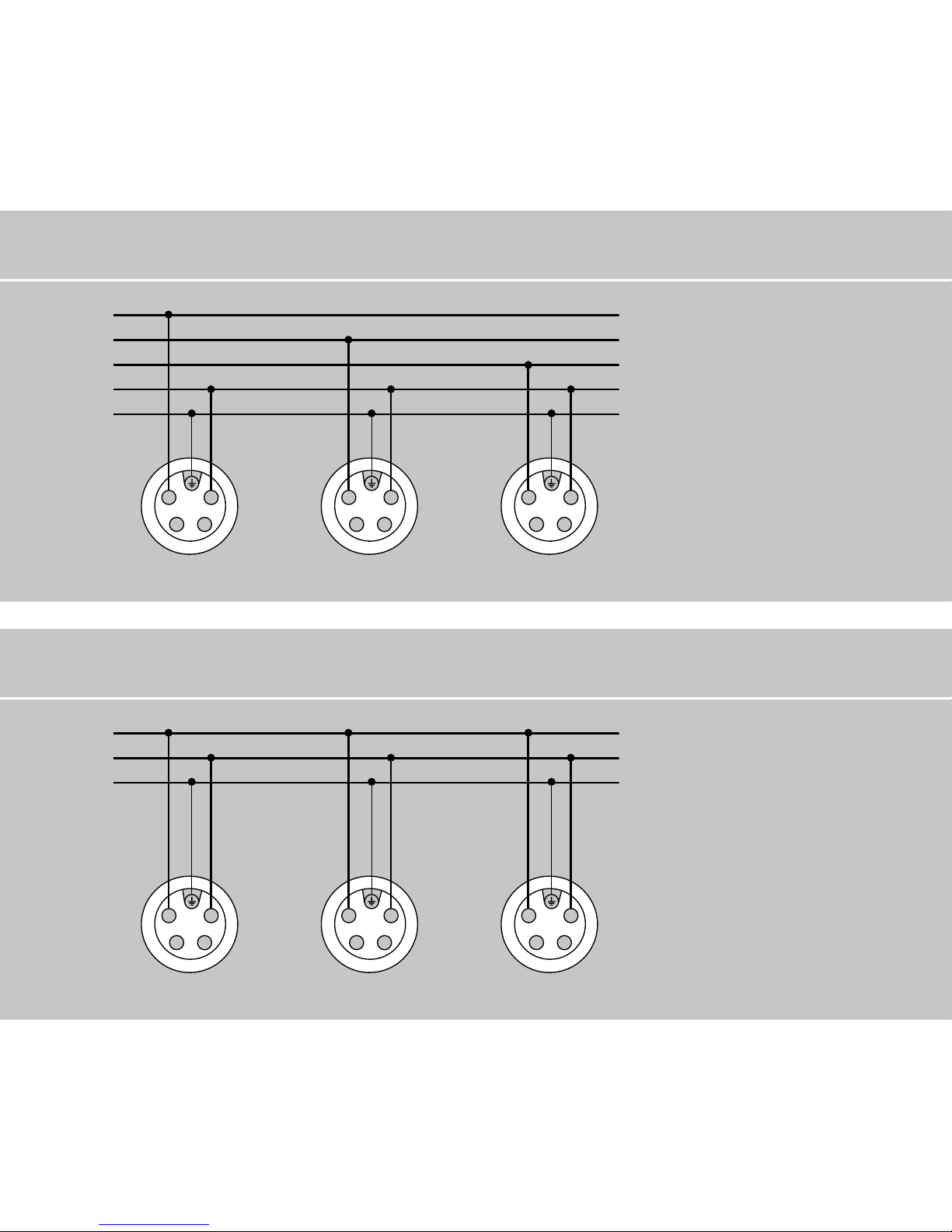
A basic distinction is made between two
different connection options of the solar
inverter to the public power grid:
· 3-phase AC grid
(e.g. Germany)
· 1-phase AC grid (e.g. Italy, Spain)
!
CAUTION
Observe the regional regulations for the
grid connection.
In Germany the grid connection must
always be 3-phase!
The solar inverter always only feeds via
AC terminal 2. If several solar inverters
are operated in parallel in a 3-phase grid,
AC terminal 2 of the unit must be distrib
uted uniformly among the grid phases
L1, L2 and L3 to avoid unequal loading.
Page 36
36
3-phase grid connection (3-phase AC connection)
PE
N
L3
L2
L1
1
2
4
3
1
2
4
3
1
2
4
3
1-phase grid connection (AC connection)
PE
N
L1
1
2
4
3
1
2
4
3
1
2
4
3
Inverter 1 Inverter 2 Inverter 3
Inverter 1 Inverter 2 Inverter 3
Page 37
37
AC bayonet connector
The AC bayonet connector is permissible
for cable sheath diameters from 13 mm
to 20 mm.
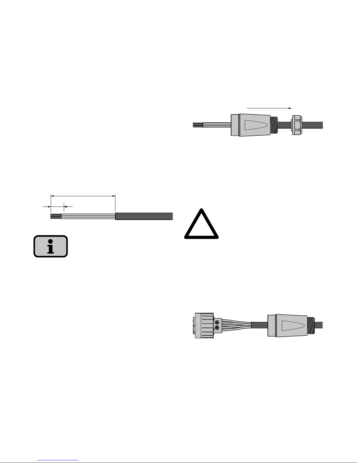
The following sequence must be ob
-
served during assembly:
1. Strip the voltage-free line and the
cable ends.
10
52,5 (PE 55)
For lines with a cable sheath diameter
from 16 to 20 mm, the cable gland must
be adapted accordingly. To do this, cut
out the inner section of the blue sealing
ring.
2. Slid the cable gland and the plug
housing onto the line.
3. Connect the cable ends to the plug
terminals in accordance with the pin
assignment.
Tightening torque: 0.7 Nm.
!
CAUTION
Observe the pin assignment of the AC
bayonet connector. An incorrect assign
-
ment can result in the unit being de
-
stroyed.
Page 38
38
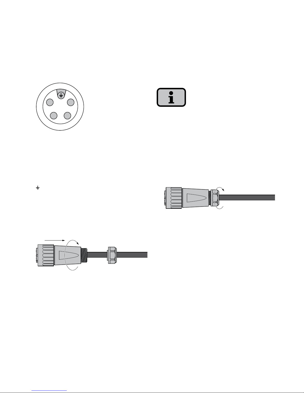
Pin assignment
1
2
4
3
1 = N
2 = L1 (feed-in phase)
3 = L2 (monitoring phase)
4 = L3 (monitoring phase)
= PE (protective earth conductor)
4. Screw plug housing to plug. To do
this, press the outer ring of the plug
toward the plug housing.
Tightening torque: 1-2 Nm.
5. Tighten the cable gland.
Make sure the line is provided with a
strain relief device. When using cables
with a diameter < 16 mm, the line must
be relieved just behind the connector.
Tightening torque for cable sheath
diameters from
13 to 20 mm = 6 to 8 Nm
Page 39
39
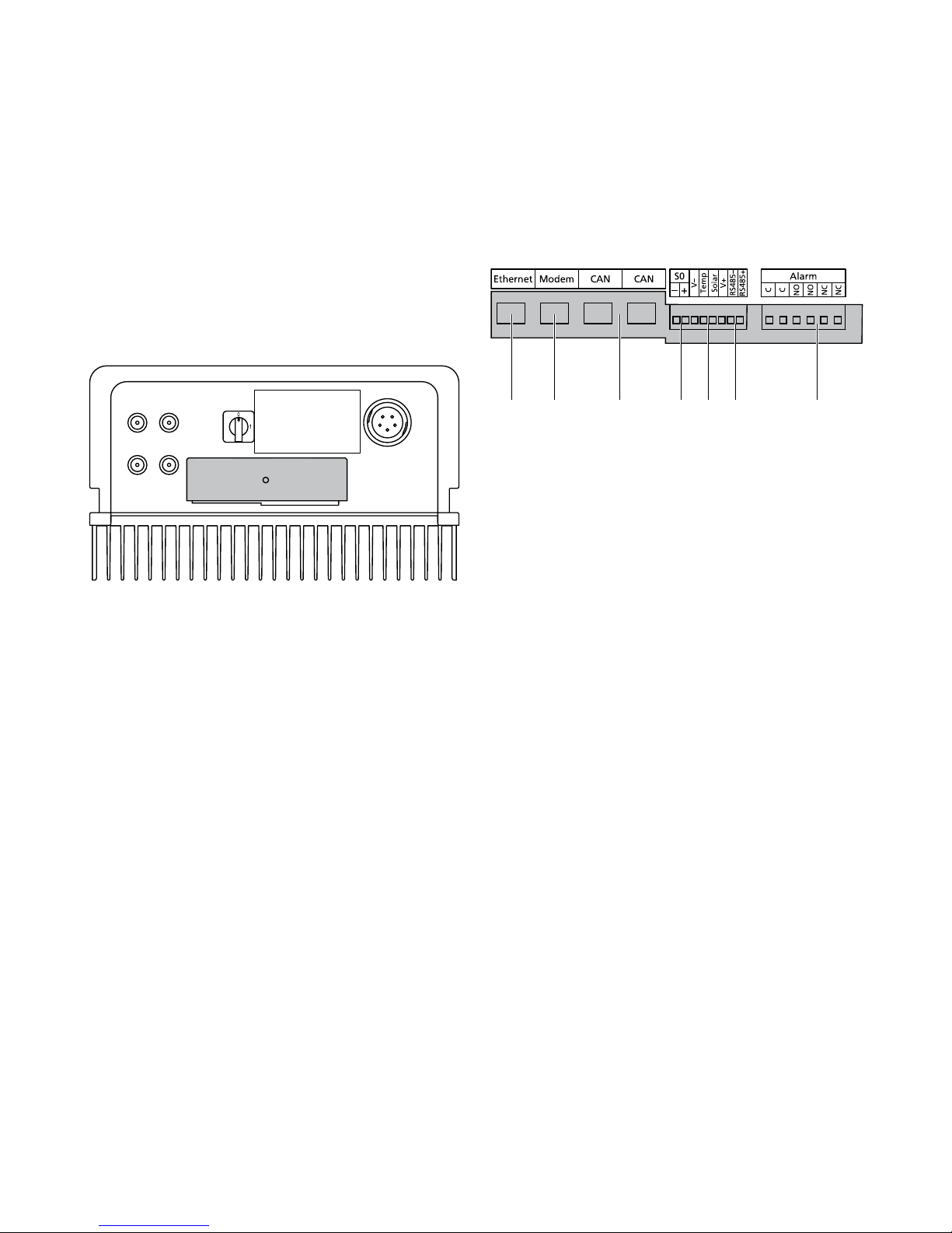
Interface overview
2
1 3 7654
1 Ethernet connection
2 Modem connection
3 CAN bus
4 S0 interface (pulse output, e.g. for
large display)
5 Connection for temperature and ir
-
radiation sensor
6 RS485 interface
7 Connection for alarm relay
3.3 Installing communication
The interfaces are located behind the
weatherproof connection box on the
underside of the solar inverter.
+–
+–
1
2
To open the connection box, loose the
centre screw. Then carefully pull way the
box toward the front.
After you have installed the connection
cable, close the box again by guiding the
locking hooks into the notches in the
housing and then pressing the box onto
the housing.
Retighten the mounting screw.
Page 40
40
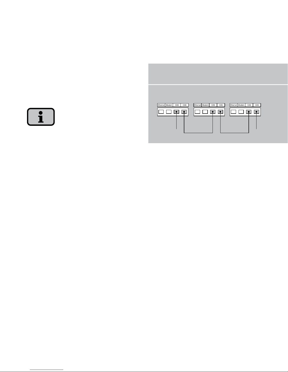
Networking solar inverters via CAN bus
The solar inverters can be networked
with each other via the CAN bus inter
-
face.
Use the included Ethernet cable to network the solar inverters with each other.
One terminating resistor (1) must be on
the first and last solar inverter in the se
ries. The pluggable terminating resistors
are contained in the delivery scope.
The total length of the CAN bus network
may not exceed 100 m!
Networking via CAN bus
1 1
Main unit Secondary units
Page 41
41
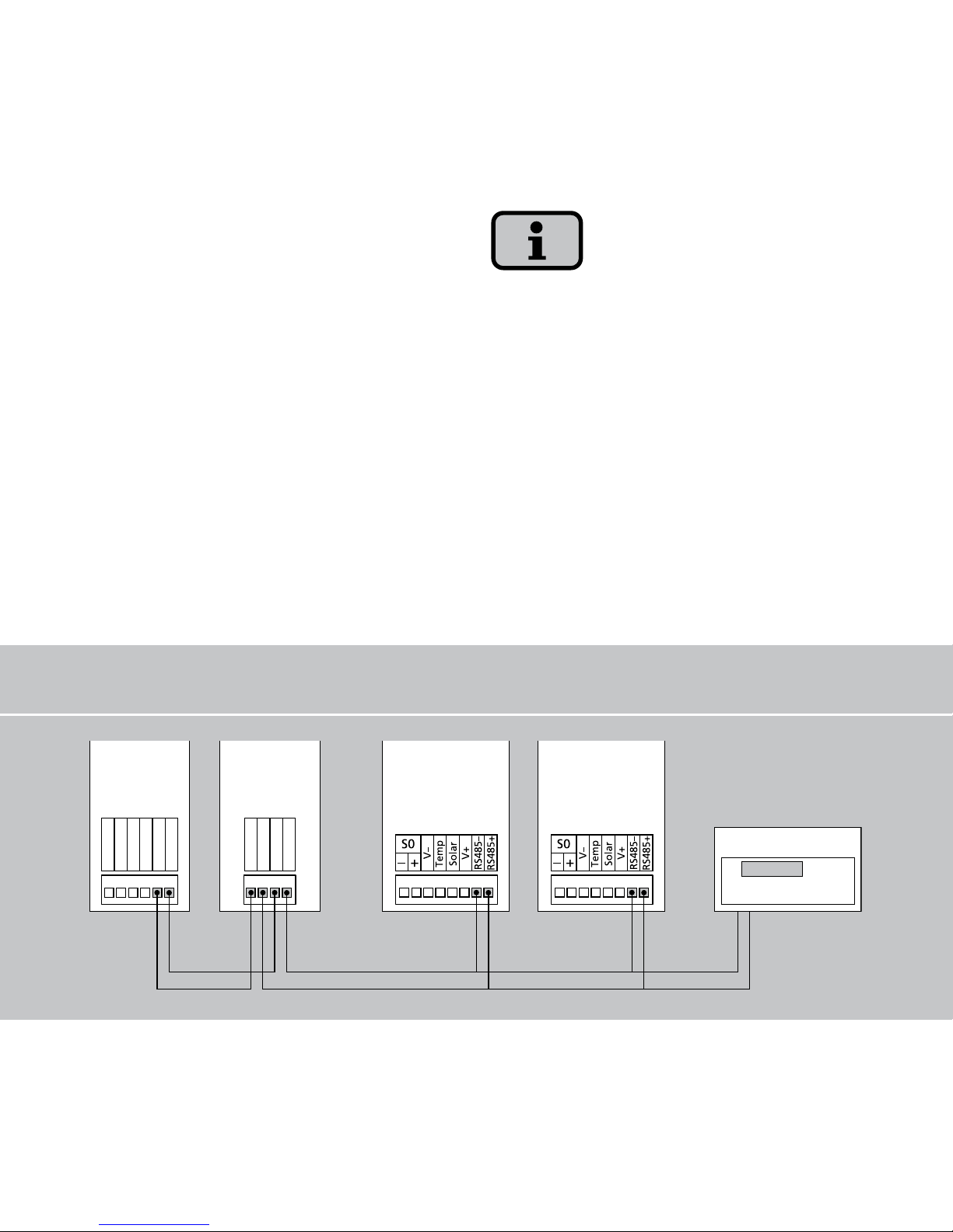
Networking via RS485 interface
RS485GND
RS485+
RS485–
RS485GND
RS485+
RS485–
RS485+
RS485–
RS485+
RS485–
Networking solar inverters via
RS485 interface
If you want to monitor a solar system
with Sunways Solar Inverters both the NT
series and the AT series together, then
you can use the RS485 interface integrat
ed in the solar inverters for this purpose.
This function is supported from AT Com
munication Software Version 2.0002. If
necessary, carry out a software update
(see the chapter Software Update). The
system networked with the RS485 inter
face can be monitored with the Sunways
Communicator.
Use a twisted two-wire cable to network
the solar inverters with each other.
Mount the terminating resistor on the
last solar inverter.
NT 10000:
RS485MATCH jumper,
NT 2600...NT 6000:
JP400 jumper
NT 10000 NT 2600...
NT 6000
AT Serie AT Serie
Sunways
Communicator
Page 42
42
S0 interface
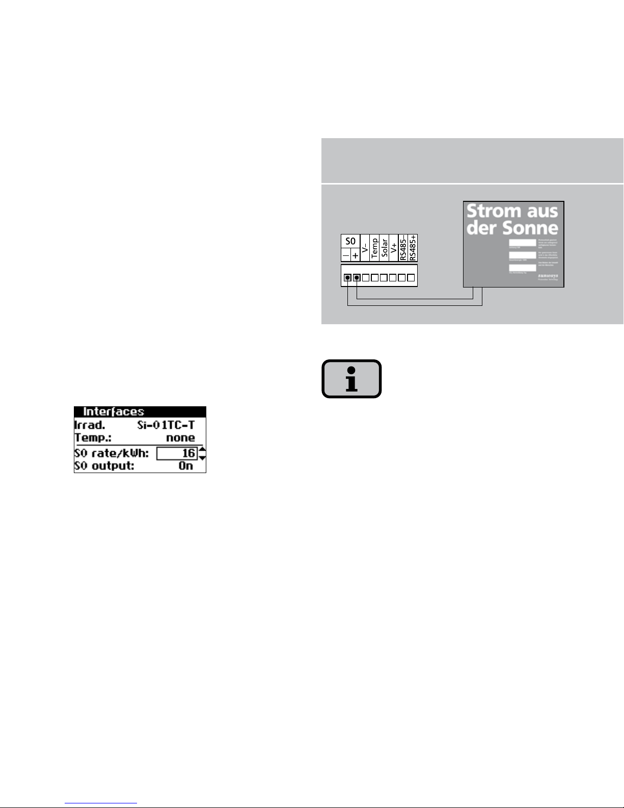
The S0 pulse output enables, for exam
ple, the connection of a large display
(Sunways Display) for displaying the
momentary output, the energy yields and
the CO
2
reduction.
You can use the S0 interface on the main
unit if you want to transmit the entire
line yields as a sum to a large display.
The S0 interface is adjusted via the
display on the inverter. Go to the menu
«Settings – Network – Interfaces».
Please note that the maximum pulse rate
may not be greater than 15 pulses/sec.
Calculate the pulse rate depending on
the size of the solar system using the fol
-
lowing formula:
Pulse rate [pulses/kWh] =
50,000/system size [kWp]
The pulse rate must be set on your solar
inverter and on the large display.
S0 interface with large display
Page 43
43
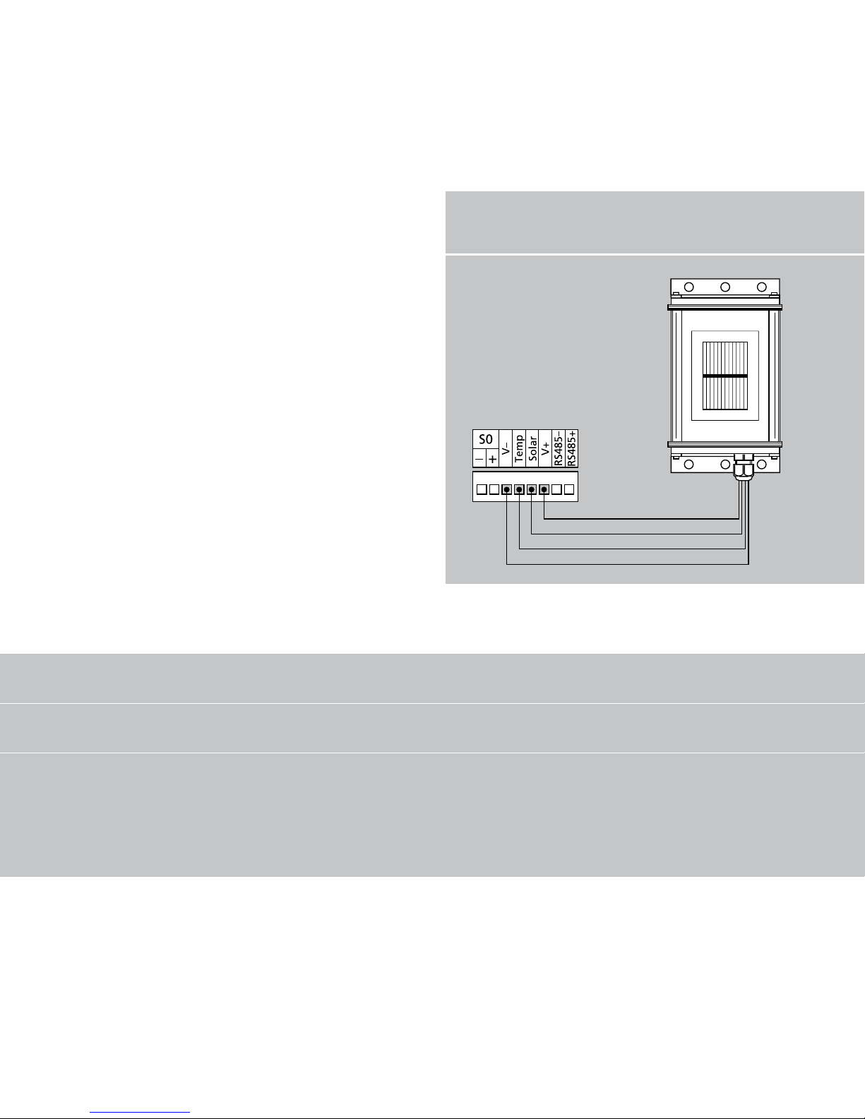
Connection of temperature and
irradiation sensor
The optional addition of an irradiation
sensor (model Si-01TC-K from Ingenieur
büro Mencke & Tegtmeyer) with an
integrated PT-100 temperature sensor for
temperature measurement enables the
acquisition of irradiation data and the
corresponding module temperature and
storage in the internal data memory as
a 5-minute mean value. This additional
measuring unit helps analyse the system
output. Based on the values, any errors
on the PV generator, e.g. shading or fail
-
ure of solar cells, can be detected.
Temperature/irradiation sensor
Assignment of sensor connection
Pin assignment
of plug sensor
Connection designation
of sensor
Connection designation
of solar inverter
Pin 1 Positive-signal irradiation strength
Solar
Pin 2 Positive-signal temperature
Temp
Pin 3 Reference earth
V-
Pin 4 Positive connection supply +5V
V+
Page 44
44
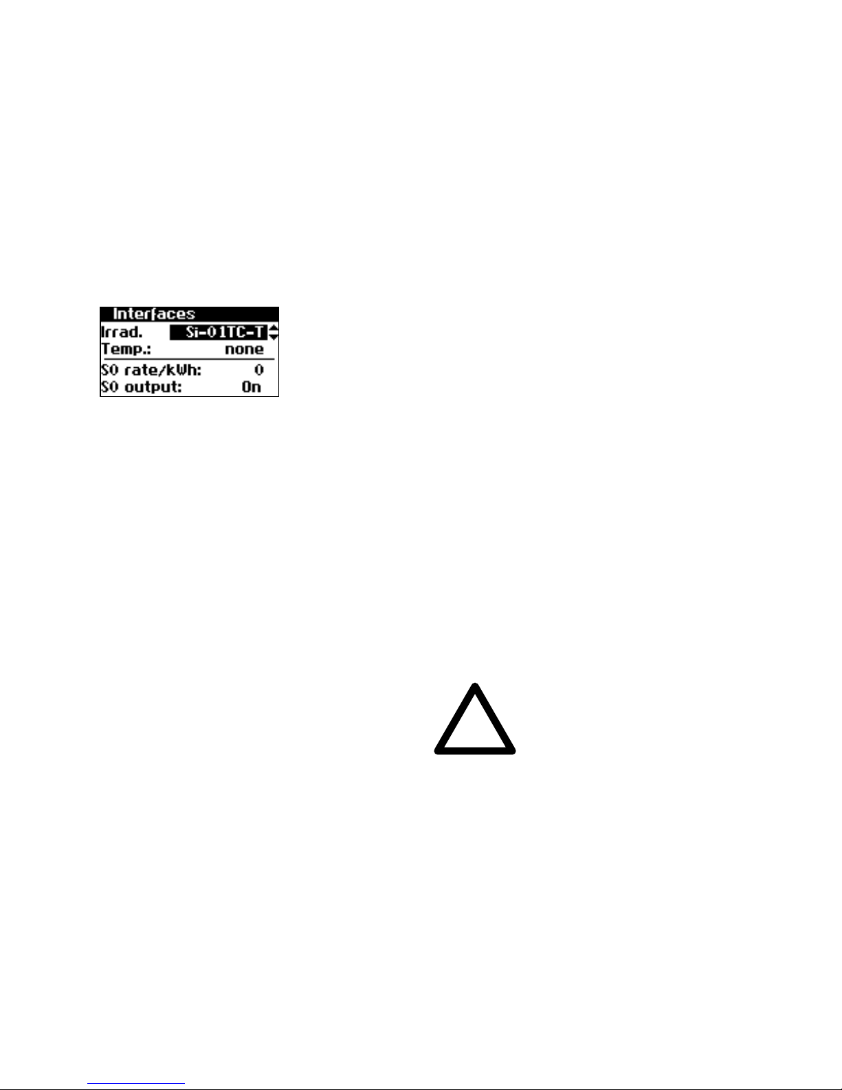
The sensor is activated via the display. In
the menu „Settings - Network - Interfac
es“ you can select the sensor type in the
«Irrad.» and «Temp.» field.
Connecting alarm relay
The solar inverters are equipped with a
potential-free alarm relay as standard.
The relay can be designed as a makecontact element or as a break-contact
element and is actuated for all malfunc
tions signalled by the device. This ensures
a faster, more reliable indication of a
possible fault in the PV system on site.
For PV systems with several solar invert
ers, the individual relays can be switched
in parallel and connected via a common
indicator lamp.
The main unit also signals faults from
other units in the CAN network via the
alarm relay. It is therefore sufficient for
simple alerting to connect the alarm
relay of the main unit.
!
CAUTION
The connected signalling unit must be
fused separately! The terminals are in
-
tended for a cable cross-section of
0.2 mm
2
to 1.5 mm2.
Page 45
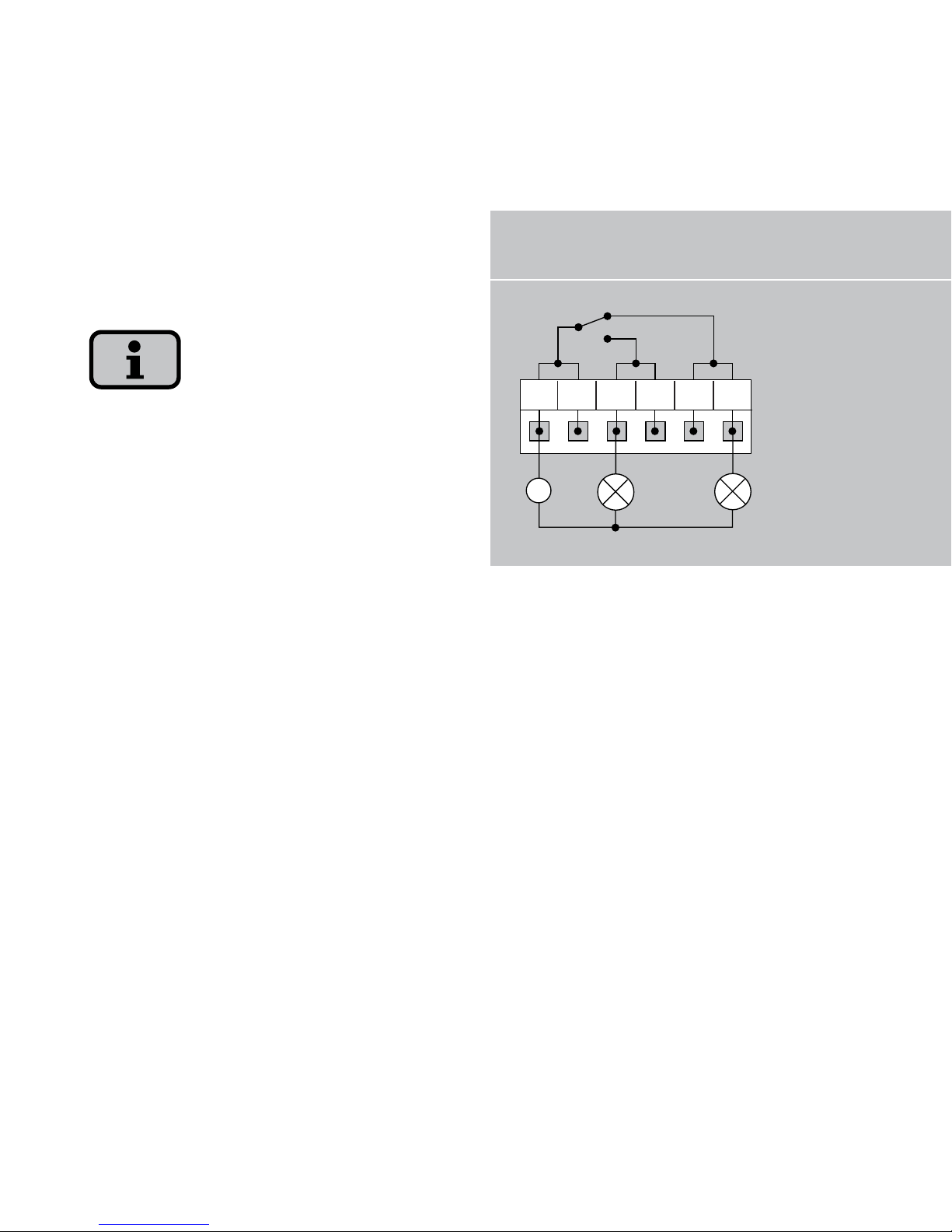
45
Wiring diagram of alarm relay - single unit
~
1 2
NO
NO
NC
NC
C
C
1 Indicator lamp, red
2 Indicator lamp, green
When dimensioning the cross-section,
also take the current consumption of the
connected signalling unit into account!
The solar inverter is supplied by the feedin phase from the AC grid. If the feed-in
phase fails, then the alarm relay cannot
switch, although a fault has occurred.
Page 46

46
4.0 Commissioning
Page 47
47
4.1 Connecting and disconnecting solar
inverter
!
CAUTION
Ensure proper mechanical and electrical
installation before commissioning the
solar inverter.
Check the proper condition of the
electrical lines.
Always separate the solar generator
side first by quickly opening the DC load
break switch and then the grid connec
tion by switching off the corresponding
mains fuse.
The Tyco Solarlok connectors of the solar
generator connection may not be discon
nected while under load. The DC load
break switch must be quickly switched to
the switching position 0.
The solar inverter is supplied from the
grid. The solar inverter switches on au
-
tomatically when sufficient solar genera
tor output is available. Corresponding
switch-on and switch-off thresholds have
been defined for this purpose.
Connecting
1. Switch on the grid connection with the
external circuit breakers.
2. Switch on the solar generator voltage
by quickly closing the DC load break
switch (switching position 1). The solar
inverter takes up operation when suf
-
ficient input voltage is available.
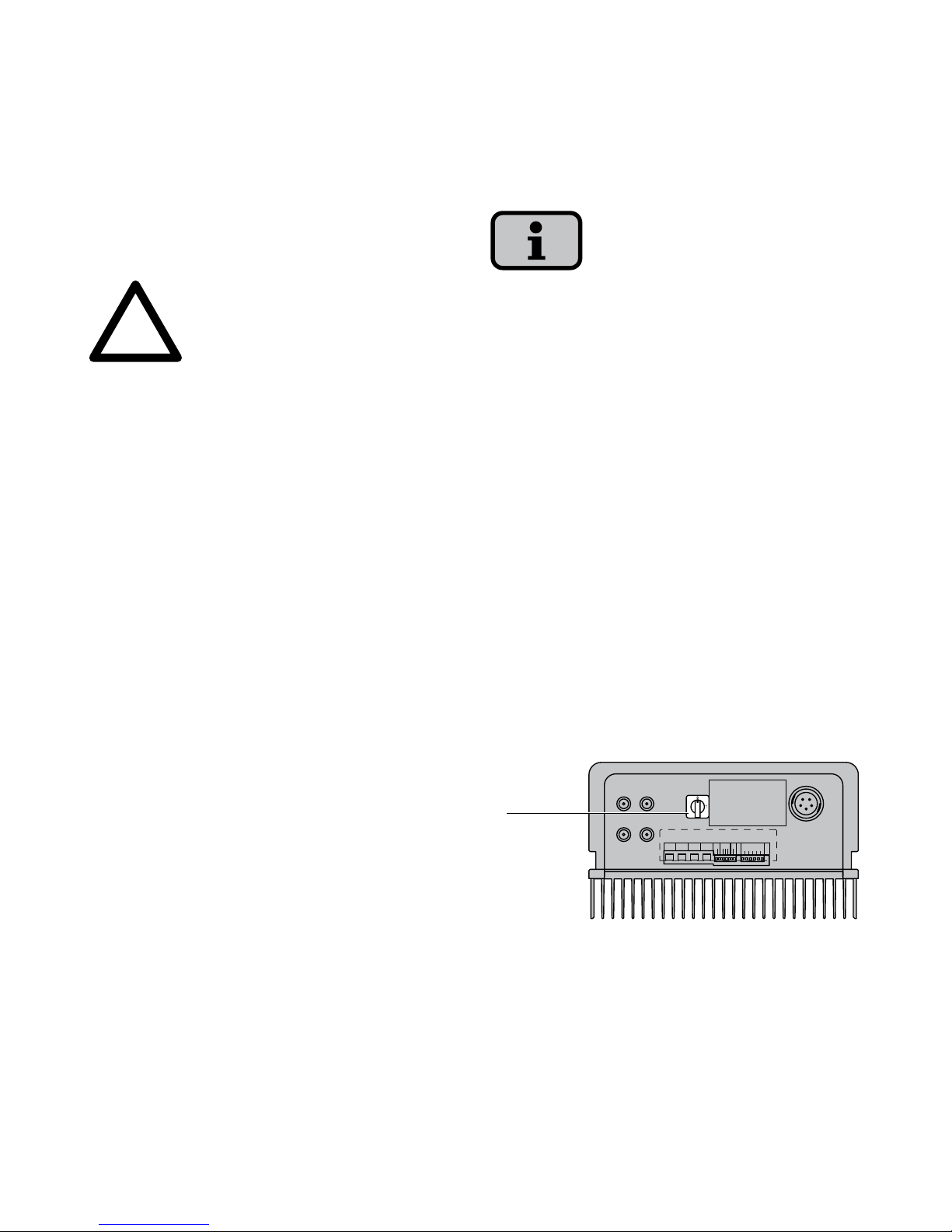
+–
+–
1
ALARM
S0
SENSOR
-+-
+
LAN MODEM CAN CAN
TEMP
SOLAR
RS485–
RS485+
COMCOM NO NO NC NC
1 DC load break switch
Page 48

48
The operating LED lights up in accordance with the operating state.
The commissioning menu opens when
the solar inverter is connected for the
first time.
Switching off
1. Disconnect the solar generator side
by quickly opening the DC load break
switch (switching position 0)
2. Open the grid connection by switching
off the circuit breaker.
Page 49
49
4.2 Commissioning
The commissioning menu is automatically
opened the first time the solar inverter is
connected. It helps you make the stand
-
ard settings.
For a better understanding of keyboard
operation, please also see the chapter
Operation.
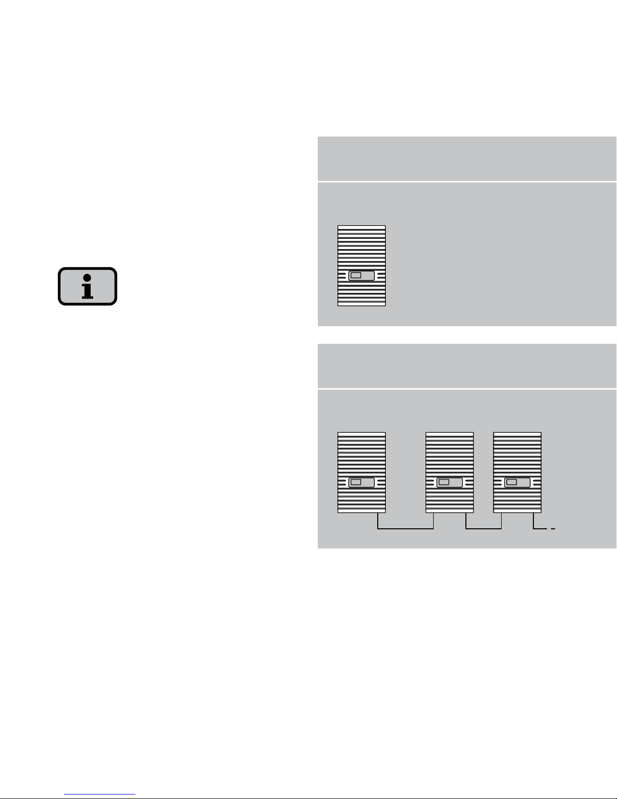
The commissioning of the solar inverter
as
· a single unit
· a main unit and secondary units with
several networked units
is described in detail in the following.
System with one solar inverter
System with several solar inverters
Single unit
Main unit Secondary units
Page 50
50
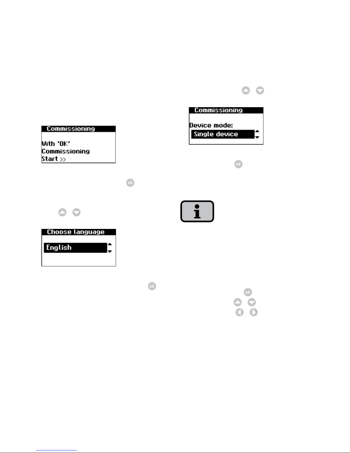
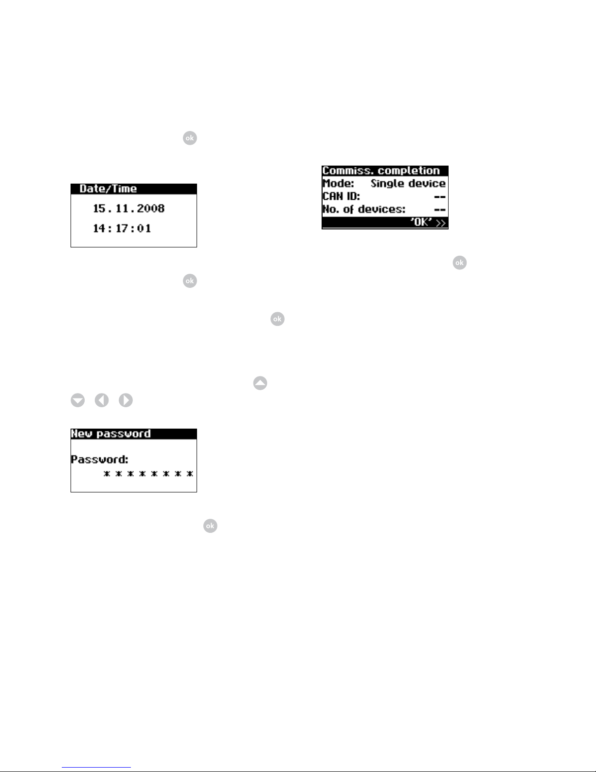
3. Select entry «Single device» in selection menu with
/
.
Confirm with
.
4. Set date and time.
Please note that time settings should only
be made with caution, as they directly af
fect data logging. For example, if you set
the time back by 1 hour, then the existing
data will be overwritten.
Select time with
. Change selected
number with
/ and jump to next
number with
/
.
Commissioning single unit
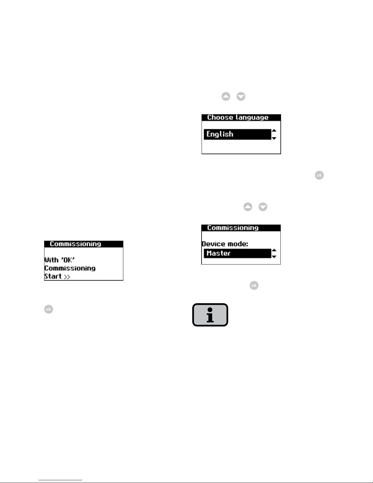
1. During initial start-up the following
appears on the display:
Start commissioning with .
2. Select language in selection menu
with
/
.
Confirm selected language with .
Page 51
51
6. Completion of commissioning
Confirm overview with .
Apply set time with
and set date in
same way as time.
Apply set date with .
5. Set password. Select password with
.
Default password is:
* * * * * * * *
A new password can be set with
/
/
/
as an option.
Confirm password with .
Page 52
52
2. Select language in selection menu
with
/
.
Confirm selected language with .
3. Select entry «Master» in selection
menu with
/
.
Confirm with
.
The other units in the CAN network are
automatically configured as slaves.
Commissioning several networked units
Before commissioning, all units must be
interconnected via the CAN bus interface.
See the chapter Networking solar invert
-
ers via CAN bus.
Switch on all units following installation.
Commissioning begins with the main unit
you have selected.
Commissioning main unit
1. During initial start-up the following
appears on the display:
Start commissioning of main unit with
.
Page 53
53
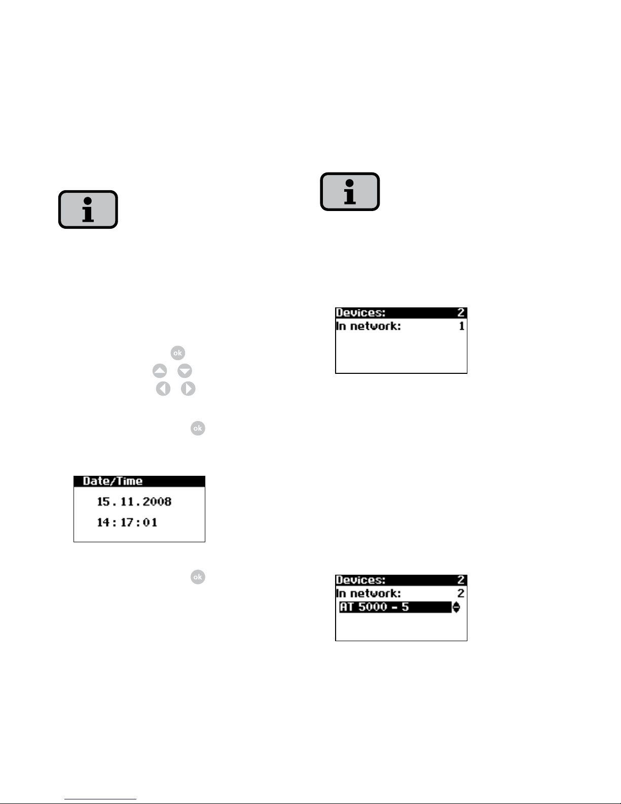
5. CAN network list is set up
Depending on the side of the network, it
may take a moment until the main unit
has found all secondary units and added
them to the list.
Units = total number of devices found
in CAN network
In network = number of configured
units
After the main unit has found all con
nected secondary unit, these must be
configured before commissioning of
the main unit is continued.
4. Set data and time centrally for all
connected units.
Please note that time settings should only
be made with caution, as they directly af
fect data logging. For example, if you set
the time back by 1 hour, then the existing
data will be overwritten.
Select time with
. Change selected
number with
/ and jump to next
number with
/
.
Apply set time with
and set date in
same way as time.
Apply set date with .
Page 54
54
Commissioning secondary units
After a main unit has been defined, the
display for requesting the CAN-ID is au
tomatically shown on the display on each
secondary unit.
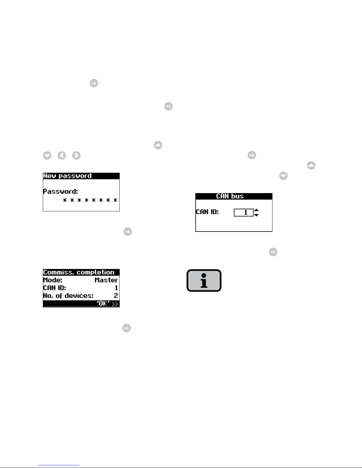
1. Request CAN ID. Change to the editing
mode with the
. Request next high-
est free ID from main unit with
or
next lowest free ID with
.
Confirm CAN-ID with .
With these IDs, the data of the individual
secondary units can be assigned in the
web interface and in the menu of the
main unit.
Confirm with
.
6. Set password. Select password with
.
Default password is:
* * * * * * * *
A new password can be set with
/
/
/
as an option.
Confirm password with .
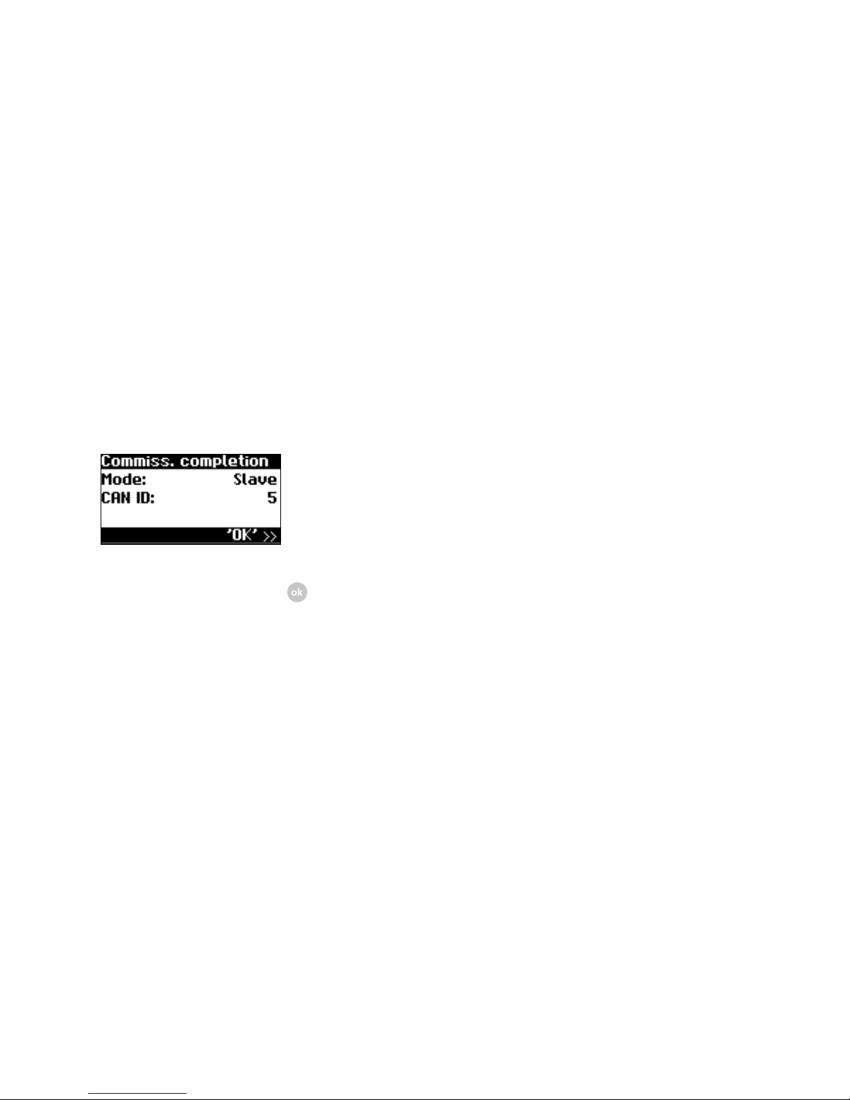
7. Completion of commissioning
Confirm overview with .
Page 55
55
The CAN-ID 1 is automatically assigned to
the master. This means the slave can be
assigned the IDs from
2 to 99.
Commissioning cannot be continued until
an ID has been requested from the main
unit.
2. Completion of commissioning
Confirm overview with .
3. Carry out commissioning for all other
slaves as described above.
Later commissioning
If you add new unit or replace existing
ones in your solar system, then you can
display the unit list in the display on the
main unit under «Settings – Network
– CAN bus». The new unit can them be
put into operation in accordance with
the description for commissioning sec
-
ondary units.
Page 56

56
5.0 Operation
Page 57
57
5.1 Operating elements
Operating field
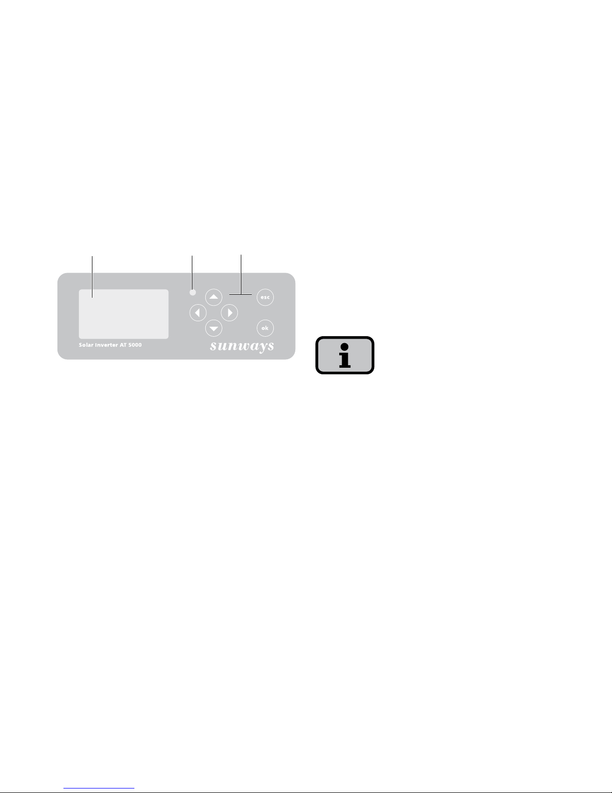
The solar inverter is operated via the
operating field on the front.
1 2 3
1 LCD display (lighted)
2 Operating LED
3 Keyboard
LCD display
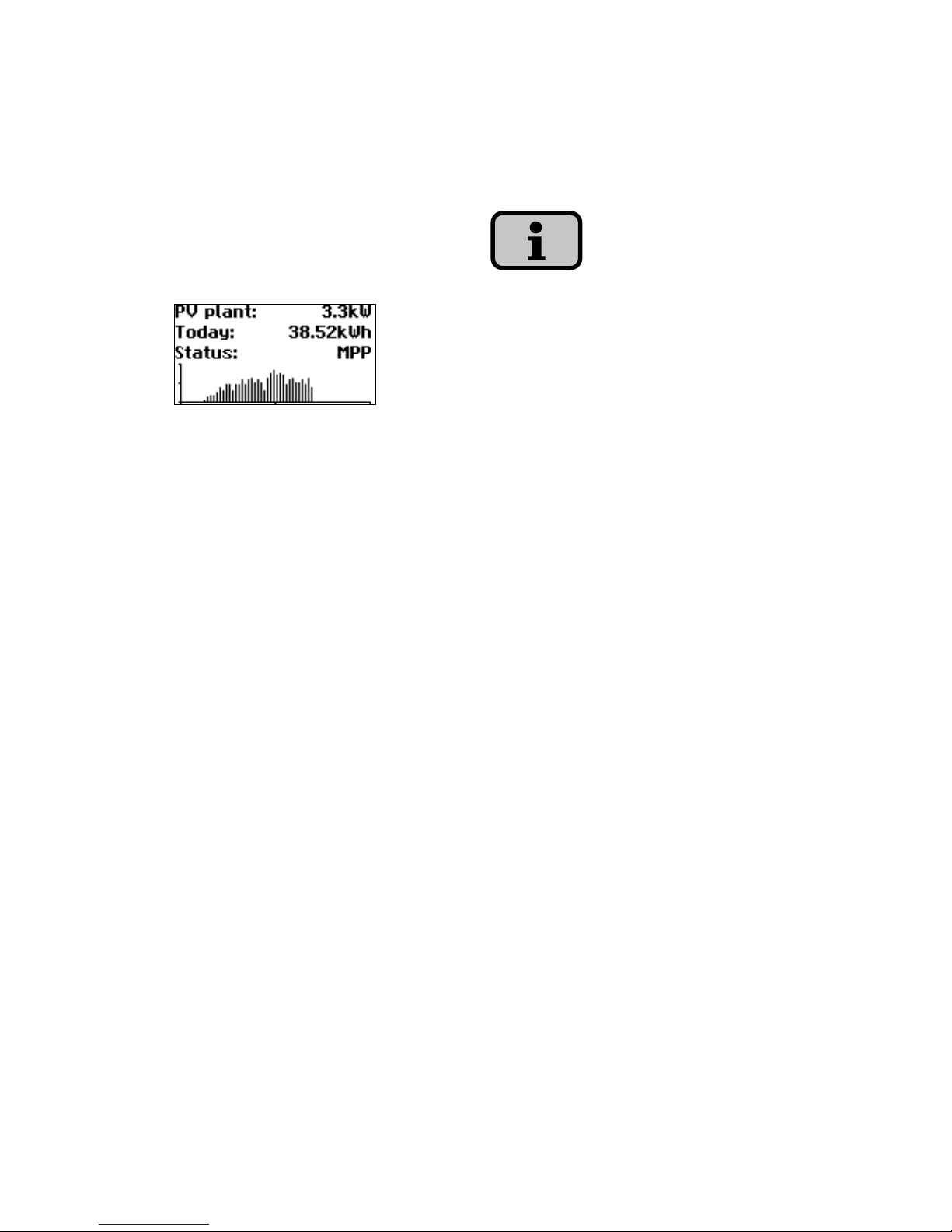
A graphics-capable, monochrome dot
matrix display is integrated in the operating field. In standard operation the
momentary output, daily yield and status
are displayed. The bar graph shows the
energy feed-in of the current day.
Press any key to activate the display light
ing. If no key is pressed for approx.
1 minute, the display lighting goes out.
Important!
The LCD display is not a calibrated
measuring device. It is characterised by a
slight, system-dependent difference of a
few percent.
Exact accounting of the data with the
power supply company requires a cali
-
brated meter.
Page 58
58
Keyboard
The keyboard can be used to navigate in
the menu, edit text fields, select entries
from lists and enter numbers consecu
tively and digit by digit. User entries can
only be made if the value to be changed
is selected. The cursor changes visibly in
the editing mode and indicates the digit
to be changed.
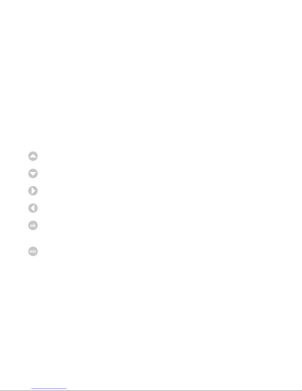
key Scroll up.
key Scroll down.
key Select menu item.
key Back one menu level.
key Select menu item and
confirm your entries.
key Cancel.
Operating LED
The combined red/green LED indicates
the unit status of the solar inverter:
· LED off
Solar inverter is not active (night
mode)
· LED green, continuously lit
Solar inverter is active and feeds into
power grid (MPP mode)
· LED green, flashing
Solar inverter is active and feeds into
power grid, however with current,
output or temperature limitation.
· LED red, continuously lit
an error has occurred (malfunction)
· LED red, flashing
a warning has been issued
Page 59
59
Standard screen (single unit)
The standard screen is always shown
when no keyboard entry is made for
more than 1 minute. It can also be shown
manually with the menu item «Solar
Inverter – Instantaneous Values».
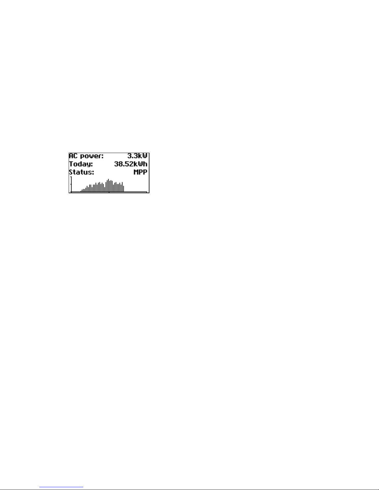
The standard screen shows the most im
portant data at a glance. In the first line
you see the momentary feed-in power. In
the second line the fed-in energy for the
day is shown.
The status signals the unit status with the
following messages:
MPP Feeding in MPP mode
AC cur.lim. Feeding with AC current
limitation
DC cur.lim. Feeding with DC current
limitation
Temp.lim. Feeding with temperature
limitation
Output lim. Feeding with output
limitation
Feed. Feeding
Warning A warning has been output
Error An error has occurred
Night Night mode
Start Initialisation phase of
unit
COM-Upd The communication soft-
ware is being updated
DSP-Upd The control software is
being updated
The graphic in the lower section of the
screen shows the energy fed in for the
day as a bar graph. The current period
is shown as a flashing bar, as it is still
increasing.
Page 60
60
Standard screen (system)
You can view the system data for a CANnetworked system with this screen.
Next to the total current system output,
you also see the energy yield of your so
lar system and any status messages of all
connected units. These are provided with
the inverter number. An „M“ means that
the error has occurred on the main unit.
The various functions are accessed via the
menu. The main menu is opened from
the standard screen by pressing the ESC
key twice.
You can always return to the standard
screen by pressing and holding the ESC
key.
If a status message is shown, then you
can open the error list directly with the
OK key.
You can access other instantaneous
values from the standard screen with the
Arrow down and Arrow up key.
Page 61
61
5.2 Access rights
Operation of the solar inverter is divided
into various areas protected with pass
words.
The password has 8 places.
If no entry is made with the keyboard af
ter entering the password, it is necessary
to reenter the password after approxi
-
mately 5 minutes.
The password can be entered in the
menu item «Settings – Login».
Customer area
The customer password must be entered
to access this area. All settings can be
made which are required for installation
and commissioning of the solar inverter.
The password for the customer area is:
* * * * * * * *
The password is preset and is directly
confirmed with
.
As an option you can assign a personal
password in the Commissioning menu.
Installer area
In this area the installer can make special
settings on the solar inverter which are
possible after consulting the technical
hotline.
A device-dependent password must be
requested from the technical hotline.
Technical Hotline +49-7531-99677577
Page 62
62
5.3 Menu structure
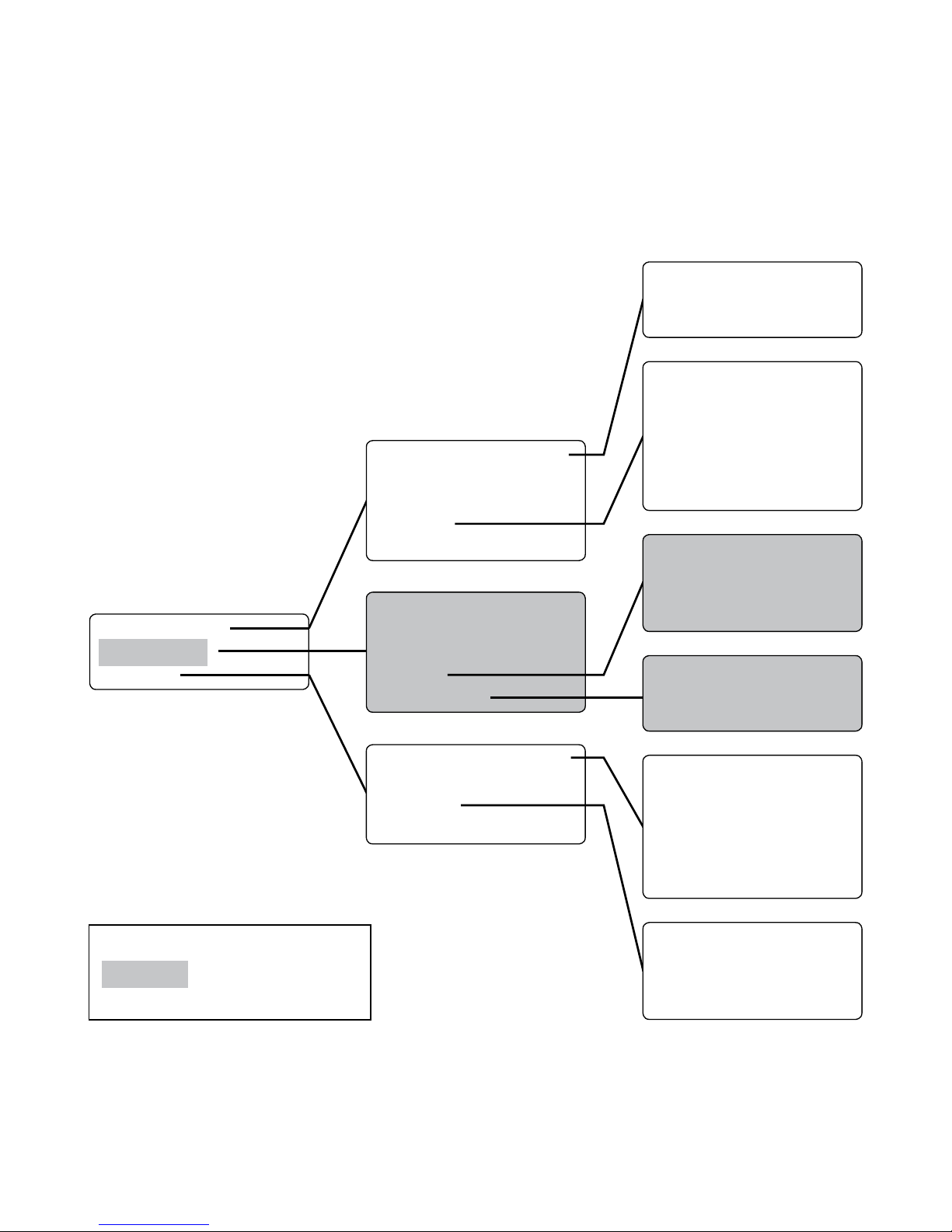
You can access all screens on the solar
inverter with the menu. The menu is
opened by pressing the left arrow key
from the standard screen.
Secondary units
Main unit
Customer area
62
Solar inverter
Solar system
Settings
Instantaneous values
Energy yield
Events
History
Information
Instantaneous values
Energy yield
Events
History
System info
General information
Login
Network
Commissioning
Yield for week
Yield for 15 days
Yield for month
Total output
DC values
AC values
Standard screen
Instantaneous values 1
Instantaneous values 2
Language
LCD contrast
Date/Time
Receiving time
Firmware
Password
Yield for week
Yield for 15 days
Yield for month
Total output
Interfaces
Ethernet
CAN bus
RS485 bus
Firmware
Memory
Mode
Page 63
63
5.4 Overview of screen displays
63
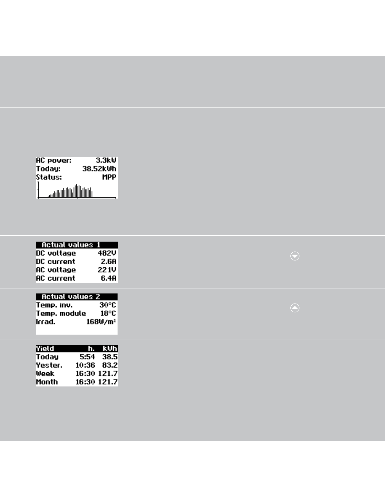
Display Description Calling Menu
Instantaneous Values – Unit
Current feed-in power, daily
energy yield and unit status
MPP Feeding in MPP mode
The screen appears auto
matically when you have
not made any entries with
the keyboard for several
minutes.
Solar inverter – Instantane
-
ous values
Display of voltages and currents from solar generator
and grid
Solar inverter – Instantane
-
ous values –
Interior temperature of unit
(Temp.Inv.) and temperature
and irradiation values (if
sensor is connected)
Solar inverter – Instantane
-
ous values –
AC yields and operating
hours from today, yesterday,
week and month
Solar inverter – Energy yield
Page 64
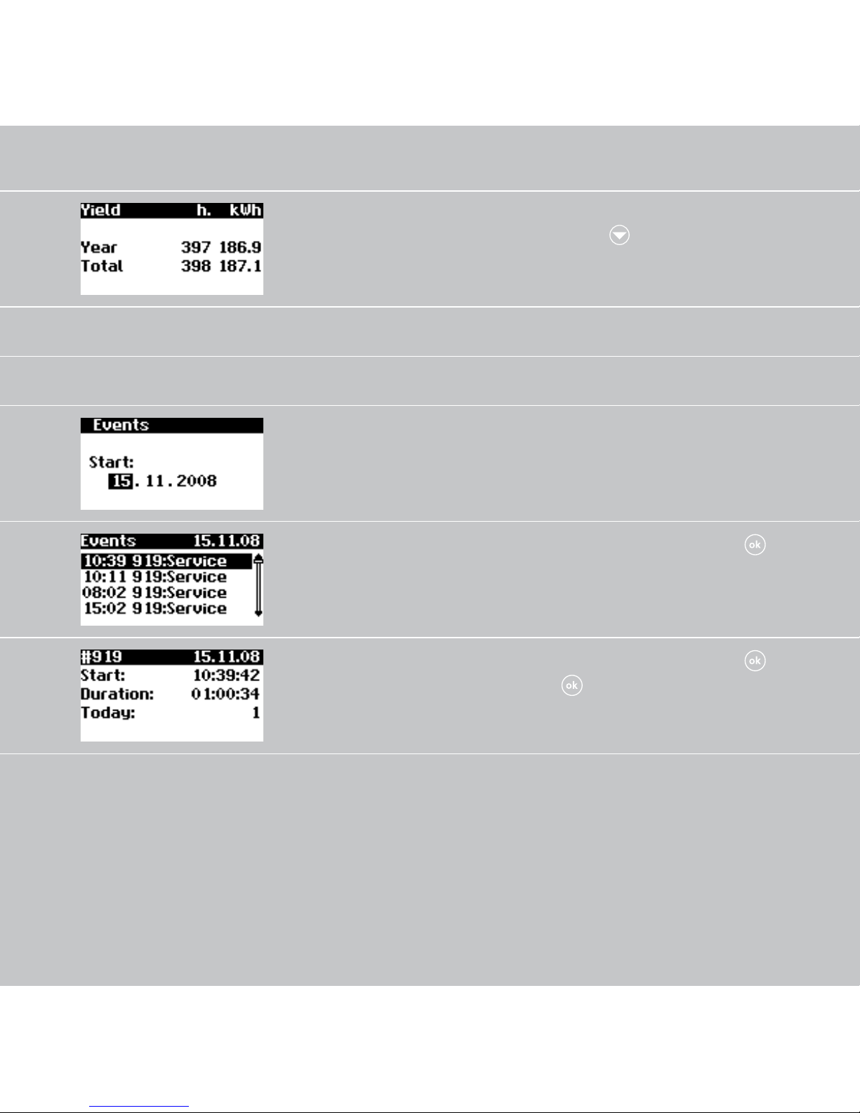
6464
AC yields and operating
hours from year and total
value
Solar inverter – Energy
yield –
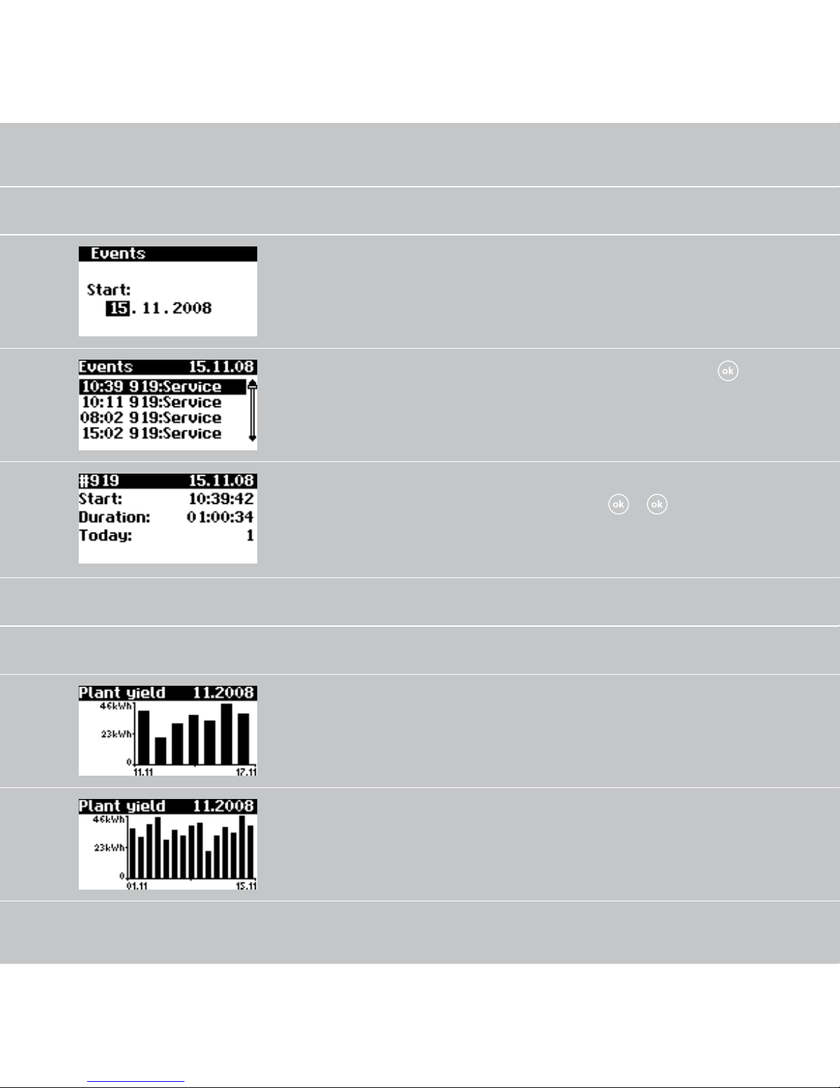
Events – Unit
Select starting data for
event display
Solar inverter – Events
Display event list Solar inverter – Events –
Display event details (error
number, data, starting time,
duration and number of oc
-
currences per day)
Solar inverter – Events –
–
Page 65
65
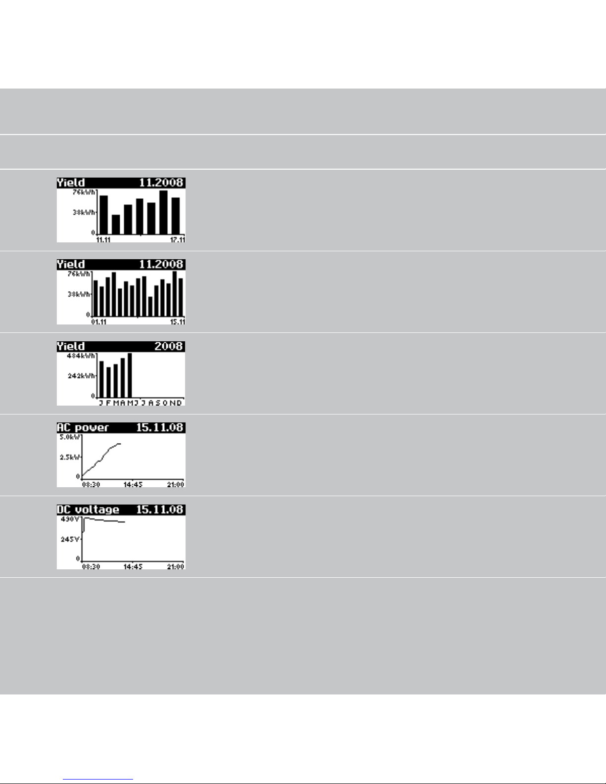
History – Unit
Daily yield for 1 week Solar inverter – History
– Yield for week
Daily yields for 15 days Solar inverter – History
– Yield for 15 days
Monthly yields Solar inverter – History
– Yield for month
AC output
(5-min. values)
Solar inverter – History – AC
output
DC voltage
(5-min. values)
Solar inverter – History – DC
output
65
Page 66
66
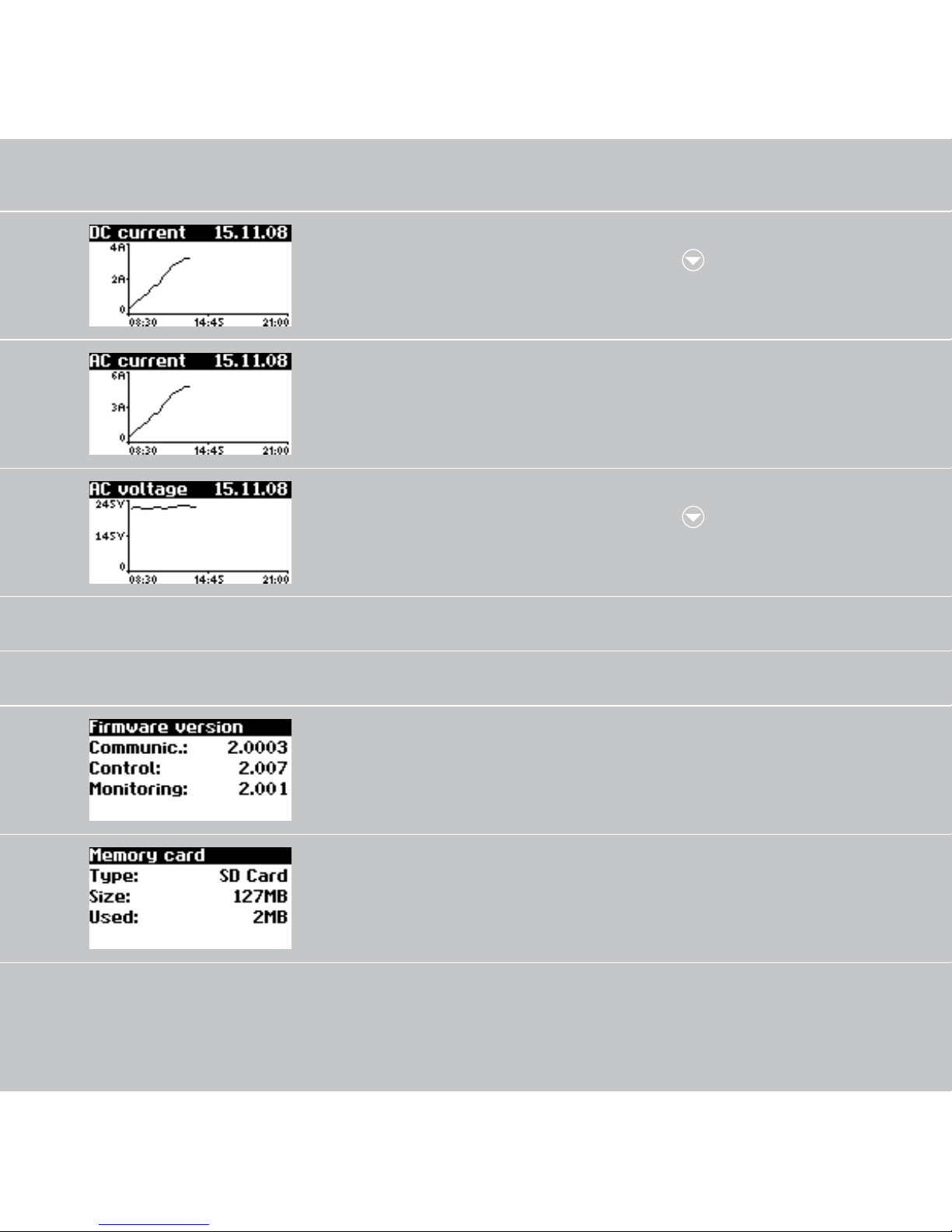
DC current
(5-min. values)
Solar inverter – History – DC
values –
AC current
(5-min. values)
Solar inverter – History – AC
values
AC voltage
(5-min. values)
Solar inverter – History – AC
values –
Information – Unit
Firmware Solar inverter – Informa-
tion – Firmware
Memory card Solar inverter – Informa-
tion – Memory
66
Page 67
67
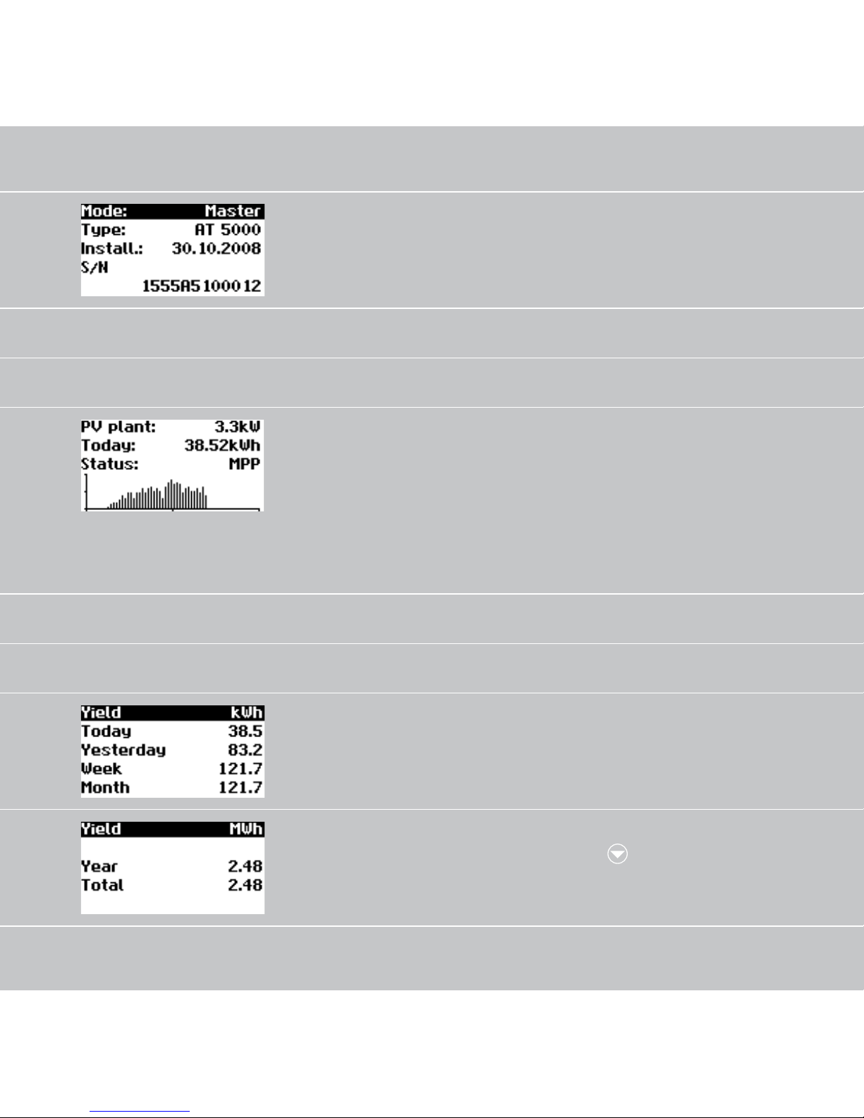
Device mode Solar inverter – Informa-
tion – Mode
Instantaneous values – Solar system (only on main unit)
Current system feed-in
power, daily energy
yield and system status
The screen appears on the
main unit automatically
when you do not make any
entries with the keyboard
for several minutes.
Solar system – Instantaneous
values
Yields – Solar system (only on main unit)
AC system yields and operating hours from today, yes
-
terday, week and month
Solar system – Energy yield
AC system yields and operating hours from year and
total value
Solar system – Energy
yield –
67
Page 68
6868
Events – Solar system (only on main unit)
Select starting data for system event display
Solar system – Events
Display event list for entire
system
Solar system – Events –
Display event details (error
number, data, starting time,
duration and number of oc
-
currences per day)
Solar system – Events – Enter
– Enter –
–
History – Solar system (only on main unit)
Solar system daily yield for
1 week
Solar system – History
– Yield for week
Solar system daily yield for
15 days
Solar system – History
– Yield for 15 days
Page 69
6969
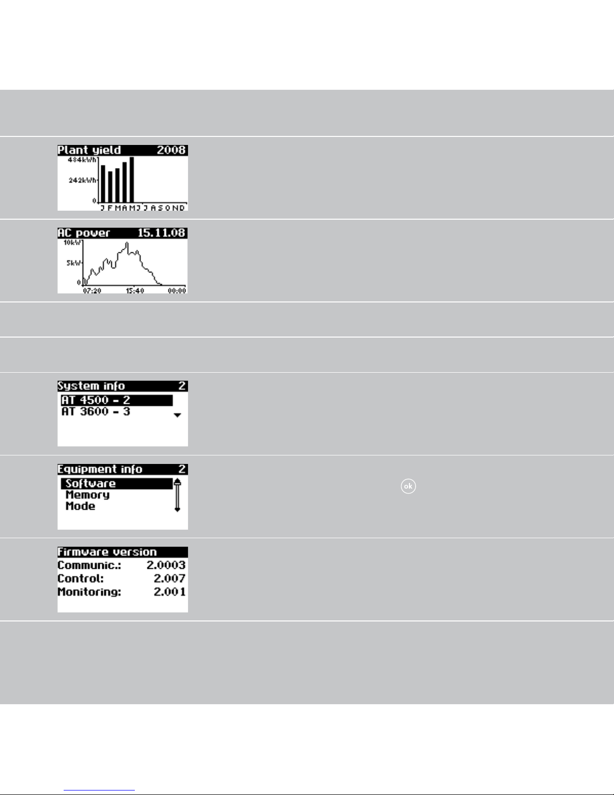
Solar system monthly yields Solar system – History
– Yield for month
Solar system AC output
(5-min. values)
Solar system – History
– AC output
System info – Solar system (only on main unit)
Unit list for selecting a unit Solar system – System info
Selection of information Solar system – System info
–
Firmware Solar system – System info
– Firmware
Page 70
7070
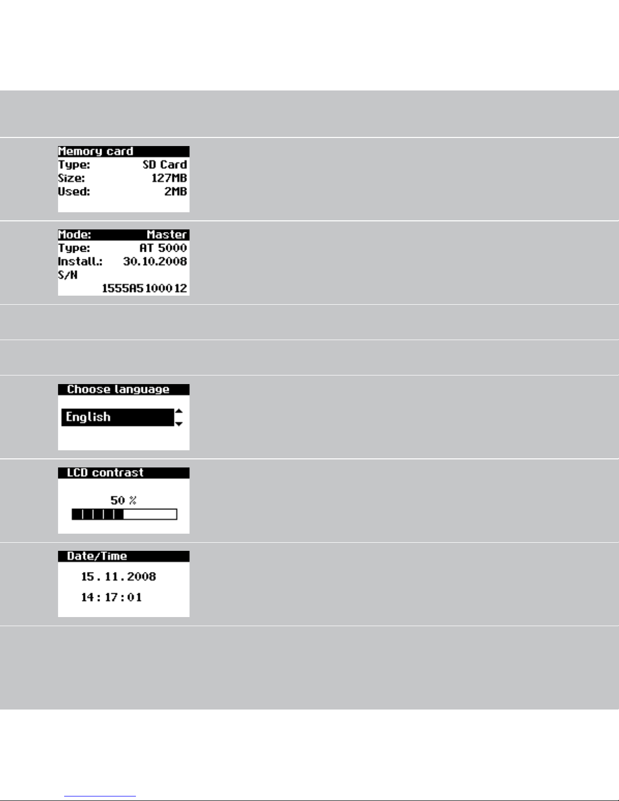
Memory card Solar system – System info
– Memory
Device mode Solar system – System info
– Mode
Settings – General
Display language Settings – General
– Language
LCD contrast Settings – General – LCD
contrast
Set date/time
(only possible with customer
password)
Settings – General
– Date/Time
Page 71
7171
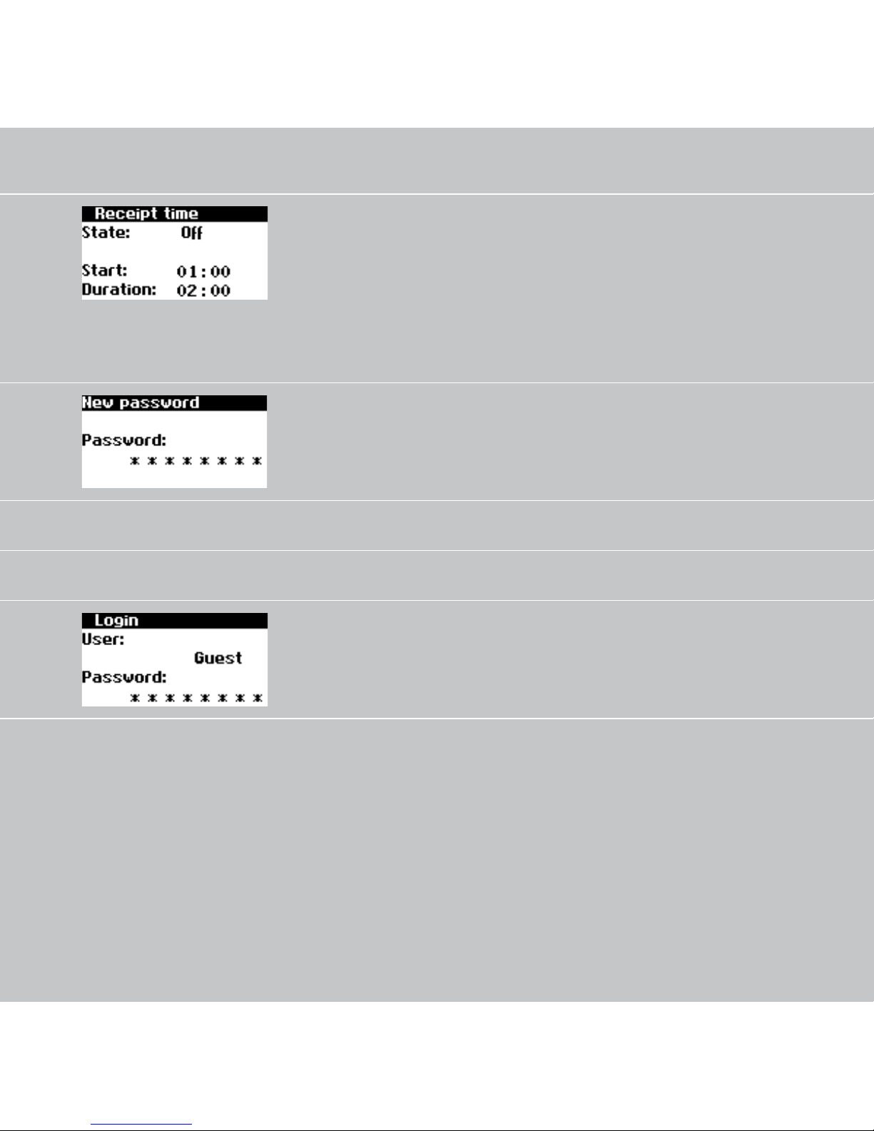
Set receiving time (starting
time and duration in which
the unit can also be ad
dressed in the night mode
via the network).
(only possible with customer
password)
Settings – General
– Receiving time
Changing the customer
password
(only possible with customer
password)
Settings – General
– Password
Settings – Login
Password entry to access
advanced settings (necessary
for commissioning)
Settings – Login
Page 72
7272
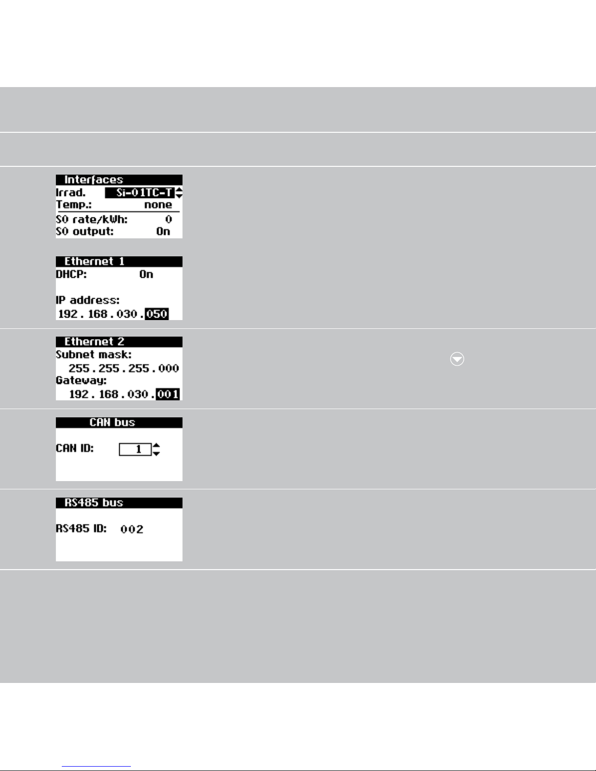
Settings – Network (only possible with customer password)
Setting of the irradiation
and temperature sensor
and configuration of the S0
pulse output
Settings – Network
– Interfaces
Network settings (Screen 1):
Activate DHCP for the auto
matic IP address setting or
enter IP address manually
Settings – Network
– Ethernet
Network settings (Screen 2): Settings – Network
– Ethernet –
Have CAN bus ID assigned
by the main unit
Settings – Network
– CAN bus
Assign RS485 address to the
unit (only necessary if NT
units are connected in the
network)
Settings – Network
– RS485 bus
Page 73

73
5.4 Malfunction displays
The solar inverter indicates malfunctions
in the LCD display and saves these in the
internal error memory.
The malfunction display consists of a
number and a short designation. Based
on the first number you can quickly recognise which area the error has occurred
in:
1: Error in the area of the solar generator
2: Error in the area of the AC network
3: Error in the area of the inverter
4: Error in the area of the interfaces/com
-
munication
9: Service error
If an error is shown in the standard
display, then you can look up the exact
error message in the menu under «Solar
inverter – Events».
You can look up the malfunction causes
yourself using the following list. First se
lect the malfunction which has occurred
and then read under Remedies what you
can do to eliminate the malfunction.
Page 74

7474
Malfunction Description Remedies
101:U-DC max Your AT solar inverter is ap-
proved for a maximum opencircuit voltage of the solar
generator of 680 V. All com
ponents of the DC input are
sufficiently dimensioned with
a safety factor. If the threshold
is exceeded, the solar inverter
stops feeding.
The maximum DC voltage
was exceeded.
➡ Check the dimensioning of
your PV generator.
Too many modules are con
nected in series.
➡ Reduce the number of mo-
dules and carry out commis
-
sioning again.
102:Insulation Before each connection, your
solar inverter checks the PV sys
tem for a possible earth fault
or insulation faults. Should this
kind of error be detected, no
feeding takes place. The mode
of operation is conformant
with DIN VDE 0126-1-1.
The solar inverter has discovered an insulation fault in the
PV system during start-up.
➡ Check your PV system for
possible insulation faults
(pinched-off DC lines etc).
The measured insulation
resistance must be at least
680 kohms.
Page 75

75
75
Malfunction Description Remedies
103:AFI>30mA Your solar inverter is equipped
with a universally sensitive AFI
according to DIN VDE 01261-1. This monitoring unit has
detected a relative residual
current jump of >30 mA.
A residual current jump has oc
curred during operation of the
solar inverter.
➡ Check your PV system for
possible insulation faults.
104:AFI>0.3A Your solar inverter is equipped
with a universally sensitive AFI
according to DIN VDE 01261-1. This monitoring unit has
detected an absolute residual
current of >300 mA.
A residual current greater than
300 mA has occurred during
operation of the solar inverter.
➡ Check your PV system for
possible insulation faults.
201:Surgef. Your solar inverter continually
monitors the quality of the AC
grid. During high voltage peaks
on the phase feeding in, the
solar inverter stops feeding and
attempts a restart.
The solar inverter has detected
a high voltage peak on the
phase feeding in.
➡ After malfunction elimina-
tion the solar inverter re
starts automatically. Should
the error occur frequently,
please contact your power
supply company.
A monitoring phase and a di
rectly earthed conductor were
exchanged when connecting
the AC side.
Page 76

76
Malfunction Description Remedies
202:UAC1>10% If the voltage of the phase
feeding in was greater than
253 V for a period of ten minutes, the solar inverter stops
feeding and attempts to switch
on again when the grid voltage is within the permissible
range. The mode of operation
is conformant with DIN VDE
0126-1-1.
The cable cross-section in the
AC supply line to the solar
inverter is too small.
Your inverter feeds into a spur
line, which is insufficiently
dimensioned.
➡ Check the design of your
grid connection (energy
meter) or the grid feed point
to your Electric Utility.
➡ Ask your Electric Utility
about grid stability and de
-
sign.
76
Page 77

77
77
Malfunction Description Remedies
203:UCA1>15% Your solar inverter continually
monitors the voltage level of
the phase feeding in. When
the maximum permissible limit
is exceeded, the solar inverter
stops feeding and does not
start up again until the voltage
value drops below the maxi
-
mum permissible limit.
The cable cross-section in the
AC supply line to the solar
inverter is too small.
Your inverter feeds into a spur
line, which is insufficiently
dimensioned.
➡ Check the design of your
grid connection (energy
meter) or the grid feed point
to your Electric Utility.
➡ Ask your Electric Utility
about grid stability and de
-
sign.
Page 78

78
Malfunction Description Remedies
204:UAC1<Min Your solar inverter continually
monitors the voltage level of
the phase feeding in. When
the minimum permissible limit
is dropped below, the solar
inverter stops feeding and
does not start up again until
the voltage value exceeds the
minimum permissible limit. If
the voltage drops below 160
V, the solar inverter cannot be
supplied.
➡ Ask your Electric Utility
about grid stability and de
-
sign.
205:UAC2>Max Your solar inverter is equipped
with a three-phase voltage
monitoring function according
to DIN VDE 0126-1-1. It con
stantly monitors the voltage
level of the individual phases
(here: L2). When the maximum
permissible limit is exceeded,
the solar inverter stops feed
ing and does not start up again
until the voltage value drops
below the maximum permis
-
sible limit.
➡ Ask your Electric Utility
about grid stability and de
-
sign.
78
Page 79

79
79
Malfunction Description Remedies
206:UAC2<Min Your solar inverter is equipped
with a three-phase voltage
monitoring function according
to DIN VDE 0126-1-1. It con
stantly monitors the voltage
level of the individual phases
(here: L2). When the minimum
permissible limit is dropped
below, the solar inverter stops
feeding and does not start up
again until the voltage value
exceeds the minimum permis
-
sible limit.
➡ Ask your Electric Utility
about grid stability and de
-
sign.
207:UAC3>Max Your solar inverter is equipped
with a three-phase voltage
monitoring function according
to DIN VDE 0126-1-1. It con
stantly monitors the voltage
level of the individual phases
(here: L3). When the maximum
permissible limit is exceeded,
the solar inverter stops feed
ing and does not start up again
until the voltage value drops
below the maximum permis
-
sible limit.
➡ Ask your Electric Utility
about grid stability and de
-
sign.
Page 80

80
Malfunction Description Remedies
208:UAC3<Min Your solar inverter is equipped
with a three-phase voltage
monitoring function according
to DIN VDE 0126-1-1. It con
stantly monitors the voltage
level of the individual phases
(here: L3). When the minimum
permissible limit is dropped
below, the solar inverter stops
feeding and does not start up
again until the voltage value
exceeds the minimum permis
-
sible limit.
➡ Ask your Electric Utility
about grid stability and de
-
sign.
209:Isol.op. You solar inverter is equipped
with a high-quality redundant
grid monitoring function ac
cording to DIN VDE 0126-1-1
and constantly monitors the
grid. If one of the phases fails,
or if the phase position be
-
tween the individual conduc
tors changes, the solar inverter
stops feeding and does not
start up again until the error is
eliminated.
➡ Check the phases L2 and L3.
➡ Ask your Electric Utility
about grid stability and de
-
sign.
80
Page 81
81
81
Malfunction Description Remedies
210:Frq1>Max The solar inverter continually
monitors the grid frequency of
the phase feeding in. If this lies
above the permissible value,
the solar inverter stops feeding
and does not start up again un
-
til the value is below the limit.
➡ Ask your Electric Utility
about grid stability and de
-
sign.
211:Frq1<Min The solar inverter continually
monitors the grid frequency of
the phase feeding in. If this lies
below the permissible value,
the solar inverter stops feeding
and does not start up again un
-
til the value is above the limit.
➡ Ask your Electric Utility
about grid stability and de
-
sign.
Page 82
8282
Malfunction Description Remedies
212:DC share Your solar inverter continually
monitors the quality of current
fed in. If an increased DC share
is found in the current fed in,
the solar inverter stops feed
ing. The solar inverter does not
attempt to feed in again until
after a reset (the next day).
➡ Restart the solar inverter.
If the error still occurs, please
contact the technical hotline.
The phone number is provided
on the back of the manual.
213:UAC1>10%
(Warning)
The voltage of the phase
feeding in is higher than 10%
above the nominal value. If
this is the case for longer than
ten minutes, the inverter stops
feeding and does not switch on
again until the voltage drops
below this limit again.
The cable cross-section in the
AC supply line to the solar
inverter is too small.
Your PV system feeds into a
spur line, which is insufficiently
dimensioned.
➡ Ask your power supply
company (PSC) about grid
stability and design.
➡ Check the design of your
grid connection (energy
meter) or the grid feed point
to your Electric Utility.
Page 83

83
83
Malfunction Description Remedies
301:AFI-Over The integrated sensor for
measuring the residual current
has been operated outside its
measuring range.
A residual current was detected
during start-up.
➡ Restart the solar inverter.
If the error still occurs, please
contact the technical hotline.
The phone number is provided
on the back of the manual.
302:Monit. The AT solar inverter is
equipped with a redundant
monitoring unit which con
stantly checks the measured
values of the controller for
plausibility. If a deviation or an
error is detected in the process,
this message appears. In addi
-
tion, this message can also ap
-
pear in case of a power failure.
➡ Restart the solar inverter.
If the error still occurs, please
contact the technical hotline.
The phone number is provided
on the back of the manual.
Page 84
84
Malfunction Description Remedies
303:Overtmp. Your solar inverter is designed
for an ambient temperature of
up to +40°C. When a specified
temperature threshold of the
heat sink is reached, the output
power is reduced linearly.
Should the heat sink tempera
ture nevertheless continue to
increase, feeding is stopped.
After the heat sink tempera
ture drops, the solar inverter
starts up again automatically.
The maximum permissible
ambient temperature has been
exceeded.
➡ The installation location
is not suitable. Please find
another installation location.
The necessary air circulation
was not taken into account
during installation.
➡ Clean the solar inverter, if
dirt prevents cooling.
➡ Observe the installation
distances specified in the
manual.
Objects were laid on the heat
sink and unimpaired convec
tion was prevented.
➡ Remove the objects.
84
Page 85

85
Malfunction Description Remedies
304:Mains rel. The AT solar inverter checks the
operation of the mains relay
prior to every switch-on. An
error was detected during this
check.
➡ Restart the solar inverter.
If the error still occurs, please
contact the technical hotline.
The phone number is provided
on the back of the manual.
305:AFI Test The AT solar inverter checks the
operation of its residual-cur
rent monitoring unit prior to
every switch-on. An error was
detected during this check.
➡ Restart the solar inverter.
If the error still occurs, please
contact the technical hotline.
The phone number is provided
on the back of the manual.
85
Page 86

8686
Malfunction Description Remedies
306:Temp mea. The AT solar inverter is
equipped with a temperature
sensor that monitors the heat
sink temperature. This message
appears if the sensor reports a
value outside its value range or
in case of a sensor cable break.
The ambient temperature of
the solar inverter is outside the
permissible range (< -25°C).
➡ Wait until the temperature
reaches the permissible
operating range.
A cable break has occurred in
the sensor which monitors the
heat sink temperature.
➡ Please contact the technical
hotline. The phone number
is provided on the back of
the manual.
Page 87
87
Malfunction Description Remedies
307:Overtmp.
(Warning)
Your solar inverter is designed
for an ambient temperature of
up to +40°C. When a specified
temperature threshold of the
heat sink is reached, the output
power is reduced linearly.
Should the heat sink tempera
ture nevertheless continue to
increase, feeding is stopped.
This warning appears when the
current heat sink temperature
is just below the switch-off
threshold.
The maximum permissible
ambient temperature has been
exceeded.
➡ The installation location
is not suitable. Please find
another installation location.
The necessary air circulation
was not taken into account
during installation.
➡ Clean the solar inverter, if
dirt prevents cooling.
➡ Observe the installation
distances specified in the
manual.
Objects were laid on the heat
sink and unimpaired convec
tion was prevented.
➡ Remove the objects.
87
Page 88

88
Malfunction Description Remedies
401:SD Card The solar inverter cannot find
an SD card.
➡ Restart the solar inverter.
If the error still occurs, please
contact the technical hotline.
The phone number is provided
on the back of the manual.
402:SD Card The SD card is write-protected ➡ Restart the solar inverter.
If the error still occurs, please
contact the technical hotline.
The phone number is provided
on the back of the manual.
403:CAN User Communication error with CAN
user.
➡ Check whether an error
has occurred in the CAN
secondary unit. Restart secondary unit and main unit
if necessary.
88
Page 89

89
89
Malfunction Description Remedies
404:CAN Bus CAN bus not in operation. No communication is possible
via the CAN bus.
➡ Check the bus lines and
the terminating resistors.
➡ Check whether the maxi-
mum permissible line
lengths have been complied
with.
➡ Check whether the bus lines
have been routed parallel to
power cables. Separate bus
lines and power cable from
each other spatially if neces
-
sary.
405:CAN User CAN user does not respond. ➡ Check whether an error
has occurred in the CAN
secondary unit. Restart
secondary unit if necessary.
Page 90

90
Malfunction Description Remedies
406:Solar
(Warning)
No sensor found on sensor
channel 1 (solar).
If you have connected a sensor:
➡ Check the connection to
your sensor.
If you have not connected a
sensor:
➡ Check the configuration
with the Sunways Browser.
407:Temp.
(Warning)
No sensor found on sensor
channel 2 (temperature).
If you have connected a sensor:
➡ Check the connection to
your sensor.
If you have not connected a
sensor:
➡ Check the configuration
with the Sunways Browser.
90
Page 91
91
Malfunction Description Remedies
408:CAN Comm
(Warning)
Communication malfunctions
occur repeatedly on the CAN
bus.
A malfunction occurs in the
data transmission on the CAN
bus.
However, a data exchange con
tinues to be possible.
➡ Check whether all connec-
tors of the bus lines and the
terminating resistors are
properly mounted.
➡ Check whether the bus lines
have been routed parallel to
power cables. Separate bus
lines and power cable from
each other spatially if neces
-
sary.
409:CAN Conf.
(Warning)
CAN bus is in the configuration
mode. No measured values are
transferred.
At least one unit is in the menu
item «Settings – Network
– CAN bus».
➡ Close this menu for all units.
91
Page 92
Malfunction Description Remedies
410:SMTP Co. SMTP server cannot be reached Check the Email settings with
the Sunways Browser.
➡ Is a valid URL or IP address
set for the SMTP server?
411:SMTP Soc SMTP no socket available Internal error or problem when
addressing the server:
no remedy available
412:SMTP Co. SMTP faulty communication
with server
Check the Email settings with
the Sunways Browser.
➡ Is a valid recipient Email ad-
dress set?
➡ Is the portal Email address
set to sunways@mail1.
meteocontrol.de in the
configuration of the system
monitoring?
92
Page 93
Malfunction Description Remedies
413:DNS Fail. DNS has failed Check whether a valid gate-
way and a valid DNS server
IP address are entered in the
network configuration.
➡ Can the inverter access the
Internet?
414:HTTP Con. HTTP client connection has
failed
Check the settings of the portal
address (www.meteocontrol.
de) and the mailbox file
(extern/sunways/pobox.php) in
the configuration of the system
monitoring
415:HTTP Aut. HTTP client authorisation has
failed
Internal error or problem when
addressing the server:
no remedy available
416:HTTP Tim. HTTP client timeout Internal error or problem when
addressing the server:
no remedy available
417:HTTP Soc. HTTP client no socket available Internal error or problem when
addressing the server:
no remedy available
93
Page 94
94
Malfunction Description Remedies
418:HTTP Soc. HTTP client error with socket Internal error or problem when
addressing the server:
no remedy available
419:HTTP Met. HTTP client incorrect method Internal error or problem when
addressing the server:
no remedy available
420:HTTP Pro. HTTP client error with protocol Internal error or problem when
addressing the server:
no remedy available
421:HTTP Wri. HTTP client write error Internal error or problem when
addressing the server:
no remedy available
422:HTTP Rea. HTTP client read error Internal error or problem when
addressing the server:
no remedy available
94
Page 95
95
Malfunction Description Remedies
9xx: Service A service error has occurred. ➡ Disconnect the solar inverter
from the grid and from the
solar generator and recon
-
nect it.
If the error occurs again, please
contact the technical hotline.
The phone number is provided
on the back of the manual.
Page 96

96
6.0 System monitoring
Page 97

97
6.1 General information
The basis for the system monitoring is the
data logger integrated in the AT solar
inverter. The solar inverters of the AT se
ries are equipped with a broad range of
monitoring options for your solar system:
· The Sunways Browser offers the dis
play of instantaneous values, stored
operating data and settings
· With active alerting the main unit can
send errors which have occurred in the
solar system to a selected recipient by
Email.
· With the Sunways Portal connection
the AT solar inverter can send the
operating data of your solar system to
the Sunways Portal daily without ad
ditional hardware. This enables you to
track your yields via the Internet.
One of the four possible connections
between a PC and the solar inverter is
possible for this purpose:
· Direct connection via an Ethernet
cable
· Connection via an existing Ethernet
network
· Connection via the Internet, e.g. con
nection of the solar inverter to a DSL
connection
· Connection via the Sunways Modem
Page 98
98
Operating Data (5-Min. Mean Values)
Qty. Value
2000 DC current
2000 DC voltage
2000 AC current
2000 AC voltage
2000 AC output
2000 Unit temperature
2000 Module irradiation (opt.)
2000 Module temperature (opt.)
Energy Yields
Qty. Value
2000 5-minute yield
800 Daily yield
800 Weekly yield
250 Monthly yield
20 Annual yield
Status Messages
Qty. Value
200 Status changes
6.2 Integrated data logger
The integrated data logger of the AT
solar inverter stores the operating data
of your solar system. In addition to 5minute mean values, energy yields are
also stored as 5-minute, daily, weekly,
monthly and annual values. Up to 200
status changes (warnings and errors with
start and end) are also stored. Each data
record contains the data and time. The
data logger is designed as a circulating
memory, i.e. the respective oldest data
are overwritten with new data.
Page 99
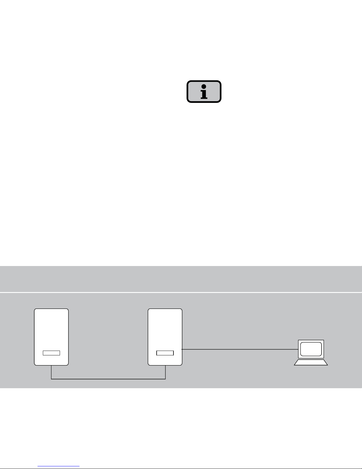
99
Direct Ethernet connection
PC
Main unitSecondary unit
Max. Ethernet
connection: 100 m
Max. total CAN bus
length: 100 m
INVERTER
INVERTER
6.3 Direct Ethernet connection
The solar inverters are equipped with an
Ethernet interface as standard for system
monitoring and configuration with a PC.
Connect your PC and the solar inverter
with a crossed or 1:1 Ethernet connec
tion cable of the type CAT5 with RJ45
sockets (automatic detection) or with the
included Ethernet cable.
The PC is connected to the main unit as
standard.
To always find the suitable configuration
for installation and commissioning on the
PC, we recommend the use of a second
network card (e.g. PCBus, PCMCIA),
which you can configure to match the de
-
fault setting of the solar inverter.
The PC and the solar inverter must have
suitable IP addresses and net masks. The
network settings can be adjusted wither
directly on the solar inverter via the LCD
display or on your PC.
Page 100
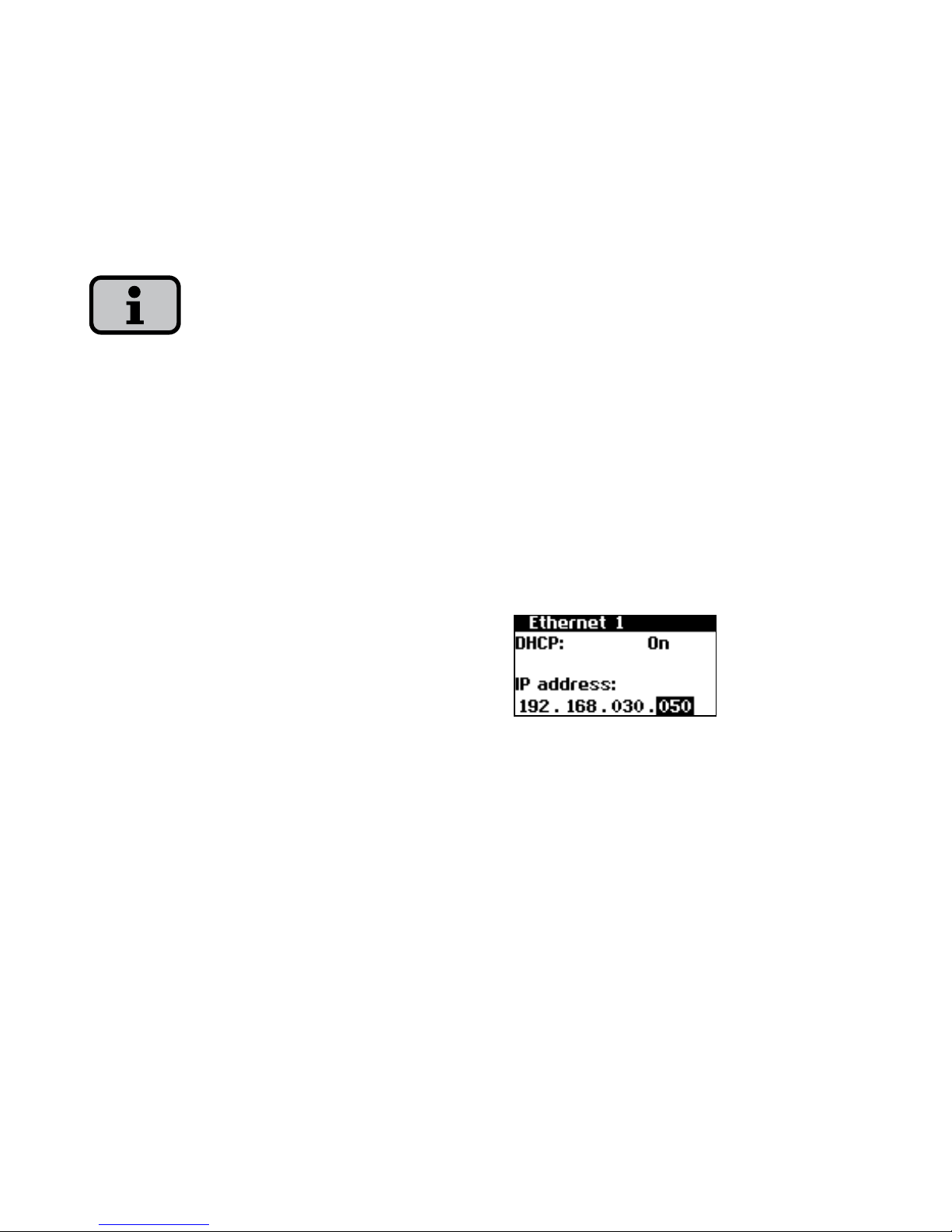
100
6.4 Network settings on solar inverter
The solar inverter is supplied with the fol
-
lowing, preset IP address:
192.168.30.50
On request you can assign your own IP
address to the solar inverter via the menu
«Settings».
In the default setting the solar inverter
does not support a DHCP (Dynamic Host
Configuration Protocol). Therefore, no
automatic assignment of the IP address
takes place. It is possible to activate the
DHCP protocol via the menu
«Settings».
IP addresses may not be assigned twice
within the network!
1. Open the menu «Settings
– Login».
2. Enter the default password (********)
or the password you have assigned
here.
3. Open the menu «Settings – Network
– Ethernet».
4. Enter an IP address suitable for use
with your PC. This means the first
three number blocks must be identical,
and the last number block different.
Example:
If your PC has the IP address
192.168.1.1, then you assign the solar
inverter the IP address 192.168.1.2
 Loading...