

Sunwave SBT - 30S, SBT - 80S, SBT-100S, SBT - 40S, SBT - 60S Instruction Manual
DIGITAL ACTIVE INFRARED SENSOR
SBT - 40S
SBT - 60S
SBT - 80S
SBT-100S
SBT - 30S
38m m
φ
~
50m m
φ
INSTRUCTION MANUAL
SUGGEST IONS FOR IN STALLATION 1
2
1
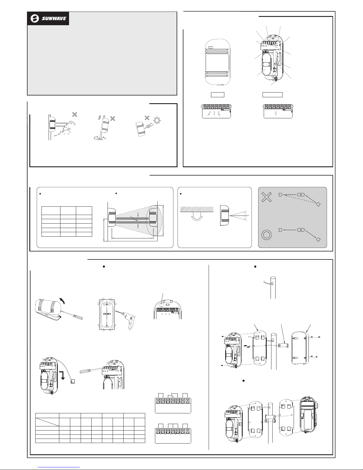
PART S DESCRIPTION
Con necti on
Termi nal
① LED
Vert ical
Adj ustme nt
Scr ew
③ Obs curat ion Time
Adju stmen t
(On ly for Re ceive r)
② Mon itor Ja ck
(On ly for Re ceive r)
Tampe r
Vie wfind er
Hor izont al Angle
Adj ustme nt Dial
Cov er Lock
Scr ew
LEN S
MAI N BODY
COV ER
Wir e Hole
REC EIVER
GOOD
LEVEL ALARM
TRA NSMIT TER
POWER
SUGGEST IONS FOR IN STALLATION 2
3
0.7
~
1.0 m
14m m
33m m
33m m
Spr ead of
Bea m
Mod el
SBT- 30S
SBT- 100S
SBT- 80S
30m
80m
100 m 3.0 m
2.4 m
0.9 m
SBT- 60S
60m
1.8 m
SBT- 40S
40m
1.2 m
Pro tecti on
Dis tance
Not e that he re the pr otect ion dis tance s
ref ers to th e sheet b elow.
Pro tecti on Dist ance
Spr ead of Be am
Hei ght of in stall ation a nd
pro tecti on dist ance
4
INSTAL LATION
1. Lo osen sc rew hol ding co ver and
rem ove the c over.
3. Br eak kno ck-ou t and pul l wire
thr ough.
4. Att ach the u nit to th e wall.
5. Co nnect w ires to t he term inal.
Wirin g dis tance
WAL L MOU NT
TER MINAL CO NFIGU RATION
1 2 3 4 5 6 7
POW ER
ALA RM
REC EIVER
TAMP ER
1 2 3 4 5 6 7
TRA NSMIT TER
POW ER
FRE E TAMP ER
kno ck-ou t
SBT- 30S
SBT- 40S SBT- 60S SBT- 80/10 0S
24V 12V 24V 1 2V 24V 12V 24 V
240 0m
440 0m
700 0m
100 00m
280 m
1120m
780 m
500 m
2
φ
2
φ
2
φ
2
φ
12V
0.3 mm ( 0.6)
f
0.5 mm ( 0.8)
f
0.7 5mm ( 1.0 )
f
1.2 5mm ( 1.2 )
f
230 0m
420 0m
670 0m
957 0m107 4m
747 m
477 m
210 0m
380 0m
610 0m
870 0m
250 m
980 m
680 m
430 m
270 m 160 0m
300 0m
490 0m
700 0m
190 m
784 m
546 m
350 m
Mod el
Volt age
Wir e
dia meter
Eac h brack et to be re verse ly atta ched.
1. Pu ll the wi re thro ugh the
wir e hole of t he pole .
2. Att ach the b racke t to the po le with t he pole h older.
Bra cket Pol e holde r Pol e cover
POLE MO UNT
Pole mo unt b ack-to-b ack
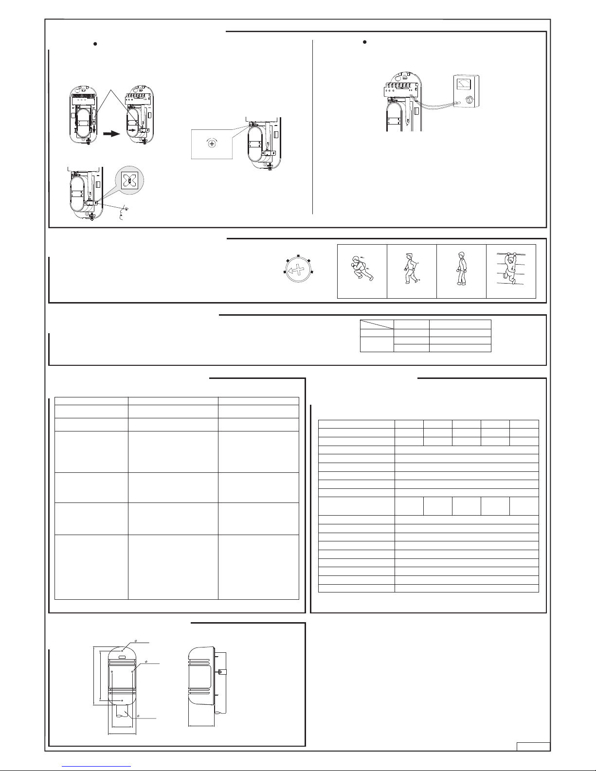
Att ach the m ounti ng patt ern
gui de hole s.
2.
Mak e the opt imum op tical a djust ment
6.
① LED
●GOO D ( Green ) ●POW ER ( Gree n )
On wh en opti cally a ligne d
●LEV EL ( Red )
●ALA RM
Int ensit y varie s with si gnal
Ala rm indi catio n lamp
Off w hen opt icall y not ali gned
② Mon itor ja ck: Sho uld be us ed for ma king th e optim um opti cal axi s adjus tment
③ Obs curat ion tim e adjus tment : To be us ed for se tting t he obsc urati on time
( Ref er to ' how t o use the m onito r jack' )
( Ref er to ' adj ustme nt of obs curat ion tim e ' )
Ens ure the s ensor s line of s ight is
fre e from any false alar m sour ces
suc h as bu shes, trees , etc. ( Pay
att entio n to the se a s th ey ma y
cha nge sea sonal ly.)
Ens ure the s ensor s are
fir m fixin g.
mou nted on a s table a nd
Ens ure str ong sun light or car
rec ommen ded.)
hea dligh ts do not s hine di rectl y
fro m th e op tical ax is is not
on to t he rece iver. (W ithin ±2°
Dir ectio n of inst allat ion
Hor izont ally 18 0°
Vert icall y 20°
Bec ause an gle of re flect ion mir ror is ad justa ble
±
uni t can be in stall ed in var ious di recti ons.
in 90°ho rizon tally an d 10°v ertic ally, the
±
pap er to th e wall, mark t he
ins talla tion ho les, an d make
ope ratio n befor e repla cing co vers.
as p er sec tion 5 and co nfirm syste m
Tran smitt er
Rece iver
Tran smitt er
Rece iver
Rece iver
Tran smitt er
In case of ju mp phe nomen on, a s sho wn ×
of tran smitt er an d re ceive r to the foll owing
sec tion in t he abov e, chan ge the di sposi tion
man ner sho wn sect ion.◎
Rece iver
Tran smitt er
10
cm
2. Lo ok thro ugh the v iewfi nder as s hown be low.
Vie wfind er
NOT E: After c omple tion of o ptica l adjus tment , ensur e
Mon itor Ja ck
1. In sert th e meter p ins int o the mon itor ja ck.
(Pa y atten tion to t he pola rity be cause o f DC volt age)
Verti cal adj ustme nt
to rai se
(loo sen)
to low er
(tig hten)
1
5
4
3
2
ADJUSTM ENT OF OBSC URATIO N
Obs curat ion tim e contr ol
CONFIRM ATION OF O PERATI ON
Aft er comp letio n of the in stall ation , confi rm corr ect ope ratio n by suit able wa lk test . Refer t o the fol lowin g LED
ind icati ons dur ing the w alk tes t. Conf irm tam per ope ratio n prior t o repla cing co vers. C onfir m syste m opera tion
wit h cover s repla ced.
Tran smitt er
Rec eiver
Con ditio ns
Tran smitt ing
Watc hing
Ala rm
Ind icati on
Gre en LED is o n
Ala rm indi cator i s off
Ala rm indi cator i s on
NOT E: Cond uct a Wal k Tes t at lea st on ce a yea r
OUTLINE D IMENSION
9
TROUBLE S HOOTING G UIDE SPECIFI CATION
Mod el
SBT- 30S SBT- 40S S BT-60S SB T-80S SBT- 100S
Pro tecti on rang e(out door)
Dis tance a llowa nce
5-3 0m
30- 40m
40- 60m 60- 80m
80- 100m
350 m 4 50m
650 m
900 m 1100m
Inf rared b eam
Det ectio n syste m
Lig ht sour ce
Res ponse t ime
Alar m outpu t
Pow er requ ired
Pow er cons umpti on
Tempe ratur e range
Tampe r outpu t
Opt ical ax is hori zonta l adjus t
Opt ical ax is vert ical ad just
Col limat or
Mea sure fo r moist ure/f rost
Oth er addi tiona l funct ion
Pla ce for in stall ation
Wei ght
2 bea ms
2 bea ms simu ltane ous cut -off de tecti on
Inf rared L ED
50- 700 mse c
Rel ay co ntac t, fo rm ' C' co ntact rat ing 3 0V AC , DC 0.5A Max.
DC 10 .5-28 V
40m A max
DC1 2-28V
45m A max
DC1 2-28V
55m A max
DC1 2-28V
65m A max
DC1 2-28V
65m A max
DC1 2-28V
-25℃ ~+55℃
Nor mally c losed v oltag e free co ntact s 30V DC, 0 .5 A Max .
±90°
±10°
Fin der ( pee p windo w )
Sli t type co ver, hea ter opt ion
Sen sitiv ity mon itori ng outp ut term inal. O k monit oring
Ind oor or Ou tdoor
600 g ( Transm itter a nd Rece iver )
82
60
146
171
2- 4.0mm
2- 5.0mm
38~50mm
Pol e
77
Cau tion: O bscur atio n time se tting s exce eding 70mse c (exce eding a sett ing of 1 ) do
Set the o bscur ation time of th e rec eiver by ad justi ng the obsc urati on ti me con trol
con ditio ns wher e there a re a lot of b irds or w ind blo wn mate rial.
5
ADJUSTME NT OF OPTIC AL AXI S
It is i mport ant to en sure co rrect o ptica l alig nmen t bet ween t he
tra nsmit ter and r eceiv er for pr oper op erati on.
HOW TO USE THE MONITO R JAC K
The b est adj ustme nt of opt ical ax is can b e done b y rea ding t he
out put vol tage of t he moni tor jac k.
7
10
W.97 .0067
6
8
Turn o n the pow er supp ly afte r unins talla tion.
1.
Adj ust t he an gle of t he le ns vi a th e Hor izont al an gle
3.
Pos sible c ause
A Reme dy
Ind icati on lamp o f Transm itter
doe s not lig ht.
Imp roper v oltag e of powe r suppl y C heck po wer sup ply and w iring
Pow er suppl y indic ation L amp
of Rec eive r d oes not li ght.
Imp roper v oltag e of powe r suppl y C heck po wer sup ply and w iring
Ala rm ind icat ion la mp do es not
lig ht eve n whe n the beams are
int ercep ted.
②
Rem ove t he r eflec ting obje ct or
Che ck two be ams to in terce pt
at th e same ti me.
Adj ust obsc urati on time set ting
to be sho rter.
Alt hough a larm LE D light s
①
Mel ted bri dge on th e s ignal
Che ck the wi ring.
It ne eds to be r epair ed.
Ala rm LED on t he Rece iver
doe s not tur n off.
Ina dequa te opti cal axi s.
Sha ding obje cts betw een t he
of the T ransm itter and /or R eceiv er.
Rea djust t he opti cal axi s.
Rem ove the s hadin g objec ts.
Cle an opti cs with s oft clo th.
Bad w iring c onnec tion.
Cha nge of su pply vo ltage .
Sha ding ob jects mov ing by w ind
Uns table i nstal latio n of the se nsor
uni t.
Inc omple te op tica l axi s ad justm ent.
Bir ds an d ot her l arge flyi ng o bject s
int ercep t the bea m.
Che ck the wi ring co nnect ion.
Che ck the vo ltage ( for sta biliz ed
sup ply vol tage. )
Rem ove t he s hadin g ob jects or
Fix s teadi ly.
Rea djust t he opti cal axi s.
Rea djust t he obsc urati on time
to be l onger o r repos ition .
①
Inf rared be am from Tran smitt er is
sen t into th e Recei ver.
Sho rter o bscu ratio n tim e tha n tha t
③
Q Sym ptom
Int ermit tent al arm.
Pla ce th e v iewfi nder on eit her r ight or le ft
han d side of t he len s whic hever make s
eas ier vie wing.
the se nsor can be se en in the cent er of the View finde r.
adj ustme nt an d the Ve rtica l adj ustme nt sc rew s o tha t
and Re ceive r. Conf irm af ter ad justm ent th at the gr een
Thi s adjus tment is c arrie d out on bo th the Tr ansmi tter
GOO D LE D is on, oth erwi se al ignme nt s hould be
rea djust ed. Th e red LE VEL LE D lamp w ill be b right er
dep enden t on high er sign al leve ls.
tha t bot h fil ters on t he re ceive r are r eplac ed
to th eir ori ginal p ositi on behi nd the mi rrors .
NOT E: If t he se nsors a re to o clo se to gethe r the n the s ignal l evel sat urate s and
2. a) Ad just th e horiz ontal a djust ment un til the o utput i s at a maxi mum.
b) Adj ust the v ertic al adju stmen t screw t o obtai n best si gnal.
(Do n ot inte rrupt b eam by ha nds dur ing the a djust ment)
3. Th e follo wing mi nimum v oltag es shou ld be obt ained t o ensur e best pe rform ance.
2.3 V f or a ll of the SBT-XX S s eries . I f th is is not obta ined then th e t ransm itter and
rec eiver s hould b e re-al igned .
the IR b eam ma y be sh ut-do wn. Thi s is no rmal an d will on ly be ac hieve d
dur ing b ench t estin g. Si gnal lev els a re r estor ed un der n ormal op erati on
dis tance s.
Sca le 1
fas t runni ng at ful l
Sca le 2 Sca le 3 Scal e 4
wal king wi th quic k nor mal wal king
slo w actio n
spe ed(6. 9m/s) ste ps(1. 2m/s) (0. 7m/s)
(0. 3~0.5m/ s)
to th e requi red set ting ac cordi ng to the s ketch b eside . The obs curat ion tim e shoul d
be se t lower t o detec t faste r movin g targe ts, how ever ca re shou ld be tak en to not e
the e nviro nment al cond ition s a s the obs curat ion tim e s hould b e set hig her to ign ore
not c omply w ith the r equir ement s in UL63 9, Inst rusio n Detec tion Un its.
int ercep ted, ala rm do es
whe n t he beams ar e
not r ing.
ref lecte d o n a nothe r o bject an d
Two beam s ar e no t in terce pted at
set o n the obs curat ion con trol.
the s ame tim e.
Bro ken wire s or sho rt o n the
(Wr ong c urren t on the sign al wi res)
con necti on
②
sig nal wir es.
Tran smitt er and th e Recei ver.
Dir ty cove r or dirt y refle ction m irror
②
③
bet ween the Tr ansit ter a nd th e
Rec eiver.
①
②
③
④
⑤
⑥
①
②
①
①
③
②
②
③
①
②
③
④
⑤
⑥
①
cha nge th e plac e for i nstal latio n
and t he opti cal axi s direc tion.
cha nge the p lace fo r insta llati on.
SHENZHEN SUNWAVE ELECTRONICS CO., LTD.
http: //w ww.sun wav e.cc
CHINA
TEL: +8 6-755-89 98-3101 FAX : +86-755- 8998-310 2
No.21 P lant, Da Wei Indu strial Zon e, Huang Ge
Heng Ga ng Town , Shenzhen
Keng,
 Loading...