

SunWare FOX-MD1 Installation Manual
Installation
FOX-MD1
Digital Multi Display
Digitales Multi Display
Multi-afficheur numérique
Multi Pantalla Digital
Digital Multi Displayen
Digital Multi Display
Multidisplay digitale
Ψηφιακη οθονη πολλαπλων
Digitale Multi Display
| DE | GB | FR | IT | ES | GR | SE | NL |
Packungsinhalt: 1 x FOX-MD1
1 x Aufbaurahmen
2 x Schrauben für Einbauversion (kurz)
2 x Schrauben für Aufbauversion (lang)
1 x Anschlusskabel, Länge 5 m
1 x Bedienungsanleitung
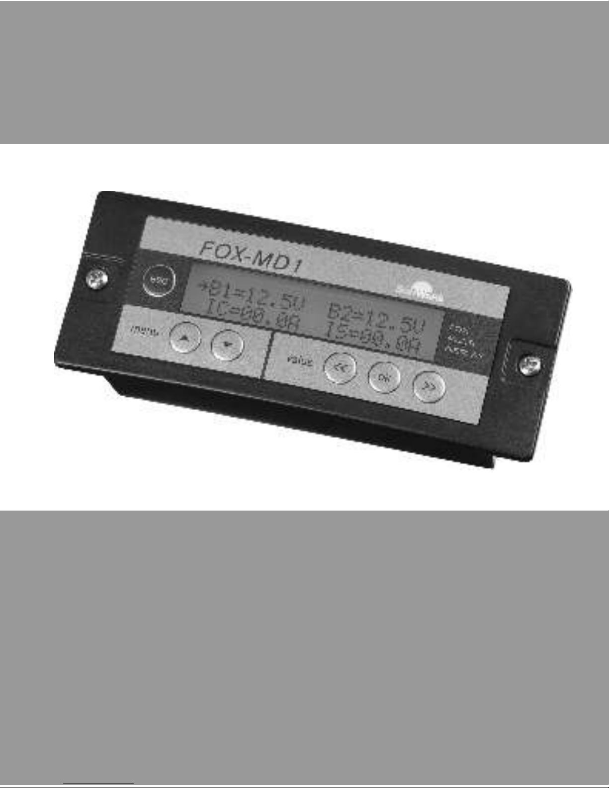
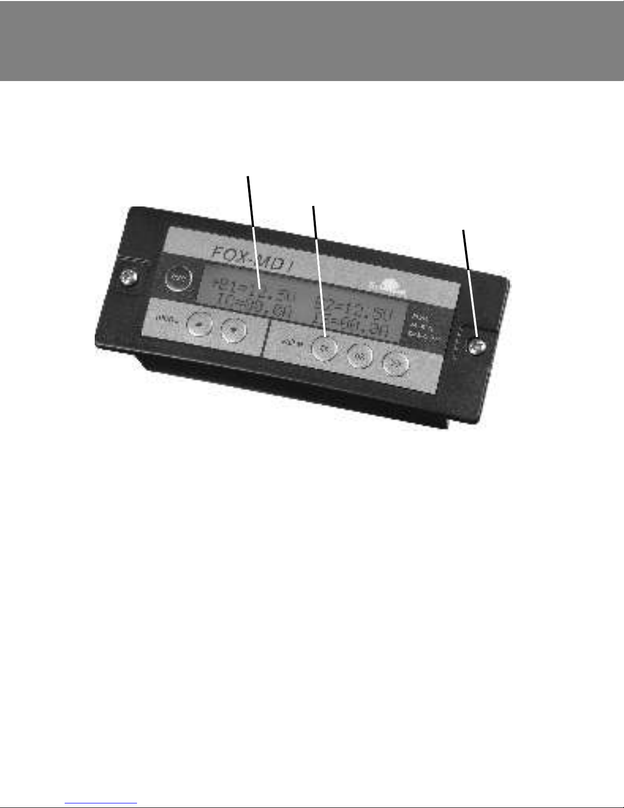
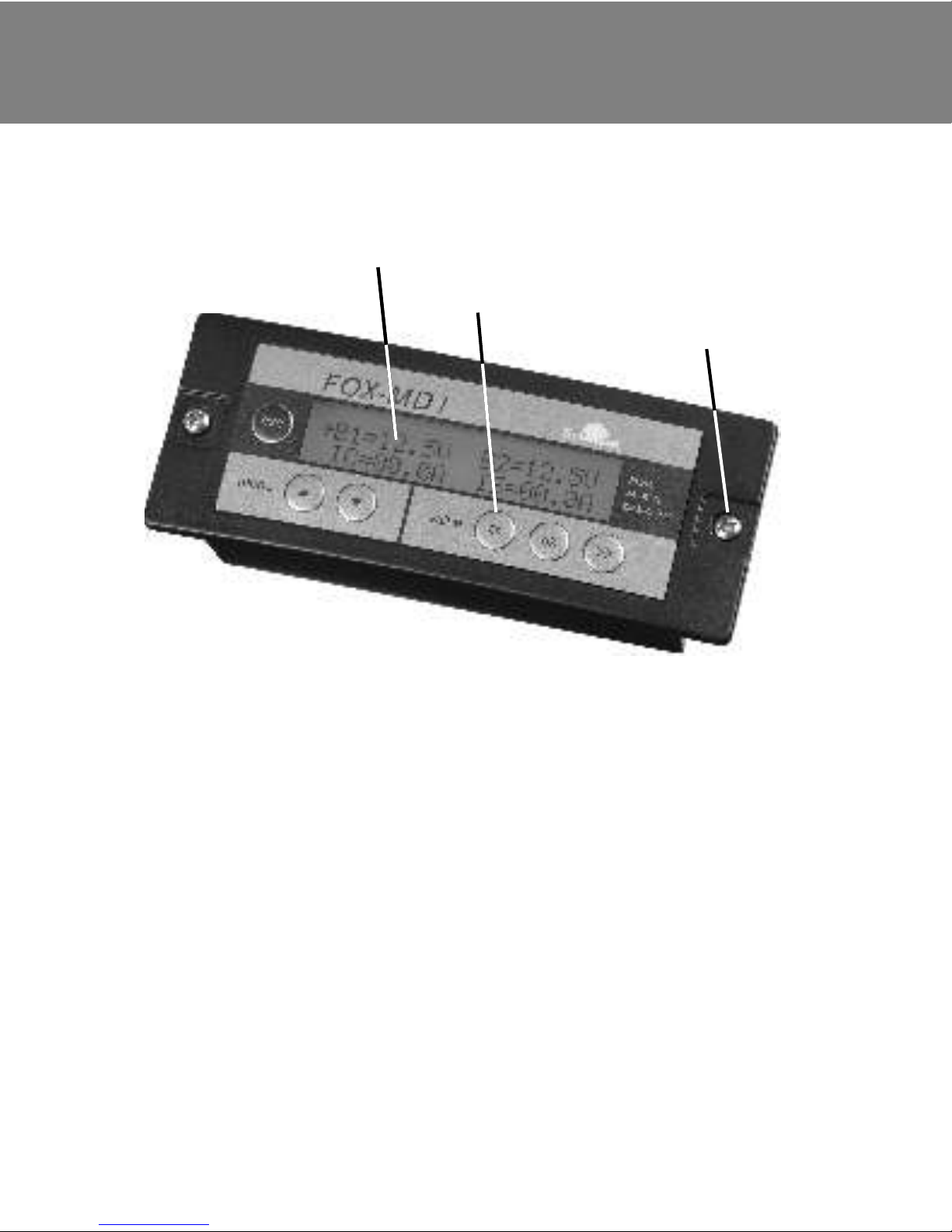
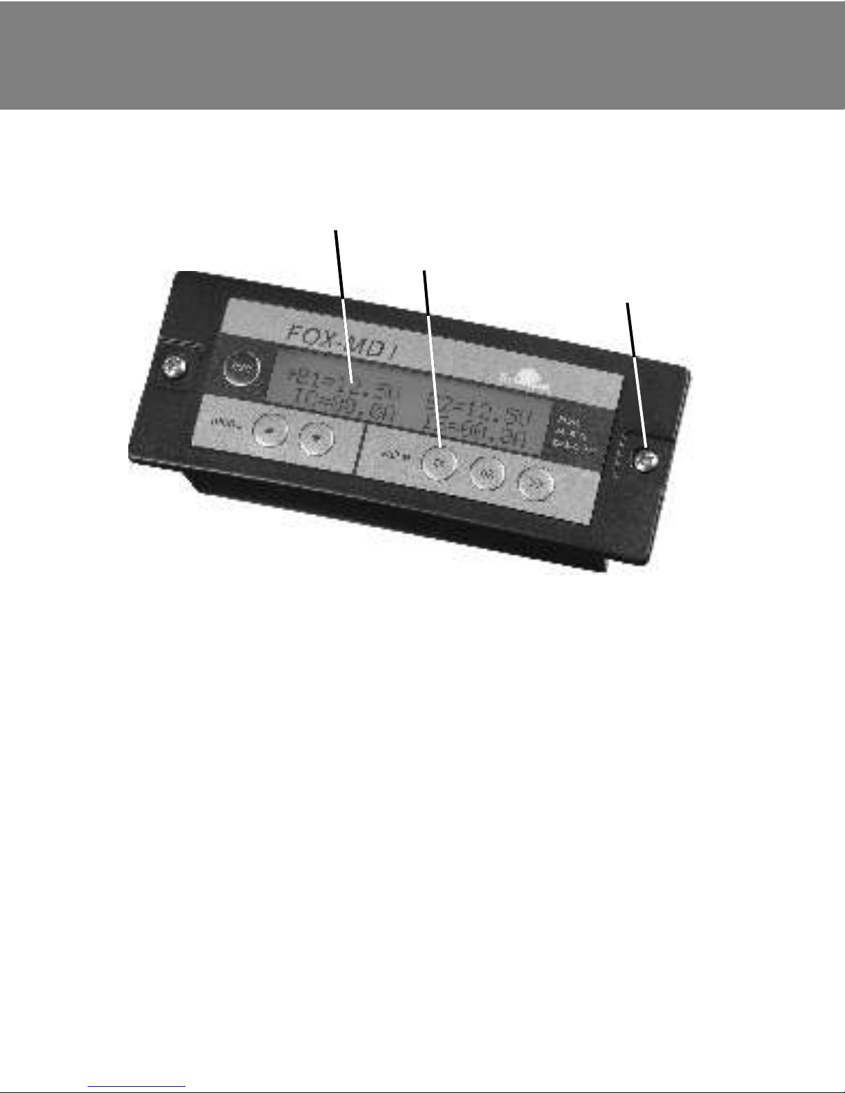
Tastatur
LCD-Display
Befestigungsschrauben
Übersicht
0 |
FOX-MD1
1

Allgemeine Hinweise
1 |
DE | GB | FR | IT | ES | GR | SE | NL
2
Bitte lesen Sie vor Inbetriebnahme des FOX-MD1 diese
Bedienungsanleitung sorgfältig durch!
· Es dürfen nur Solarmodule als Spannungsquelle angeschlossen
werden - keine Windgeneratoren oder andere Ladegeräte.
· Schließen Sie die Anschlussleitung niemals an Ihren Computer,
Netzwerkgeräte oder andere Geräte mit RJ45-Buchse an. Diese
Geräte können dadurch zerstört werden.
· Alle Vorsichtsmaßnahmen für Arbeiten mit Batterien und
Leistungselektronik müssen eingehalten werden.
· Das Display darf nicht mit Wasser oder kondensierender
Feuchtigkeit in Kontakt kommen.
· Das Display darf nur in geschlossen Räumen verwendet werden.
· Vor direkter Sonneneinstrahlung schützen.
Wichtige Hinweise:
[ ! ]

FOX-MD1
Wir freuen uns, dass Sie sich für den FOX-MD1 entschieden haben.
Schon bald nach der einfachen Installation werden Sie das große,
beleuchtete Display mit all seinen Informationen über Ihre Solaranlage
nicht mehr missen wollen.
Der FOX-MD1 ist eine Fernanzeige für diverse FOX-Geräte.
Die Fernanzeige wird einfach mit dem fertig konfektionierten Kabel mit
dem FOX Gerät verbunden.
Durch das große Display mit Hintergrundbeleuchtung können selbst in
dunklen Umgebungen die Daten leicht abgelesen werden. Erfolgt
10 sec. kein Tastendruck, schaltet sich die Hindergrundbeleuchtung
automatisch wieder aus.
Der FOX-MD1 zeigt je nach angeschlossenem Gerät unterschiedliche
Daten an. Ebenso lassen sich in Abhängigkeit vom angeschlossenen
Gerät Parameterwerte und Funktionseinstellungen verändern.
Der FOX-MD1 kann als Einbau- oder auch als Aufbaugerät verwendet
werden. Hierzu liegt jedem FOX-MD1 ein Aufbaurahmen bei.
Der FOX-MD1 darf nur an speziell dafür entwickelte und unten
aufgeführte FOX-Geräte angeschlossen werden:
· Laderegler FOX-220 Version 1.0 bis 4.5
· Laderegler FOX-320 Version 1.0 bis 4.5
Liegt die Versionsnummer des angeschlossenen FOX-Geräts höher als
die des FOX-MD1, werden unter Umständen nicht alle Funktionen
des Geräts unterstützt.
Funktionsbeschreibung
2 |
3

Montage und Inbetriebnahme
3 |
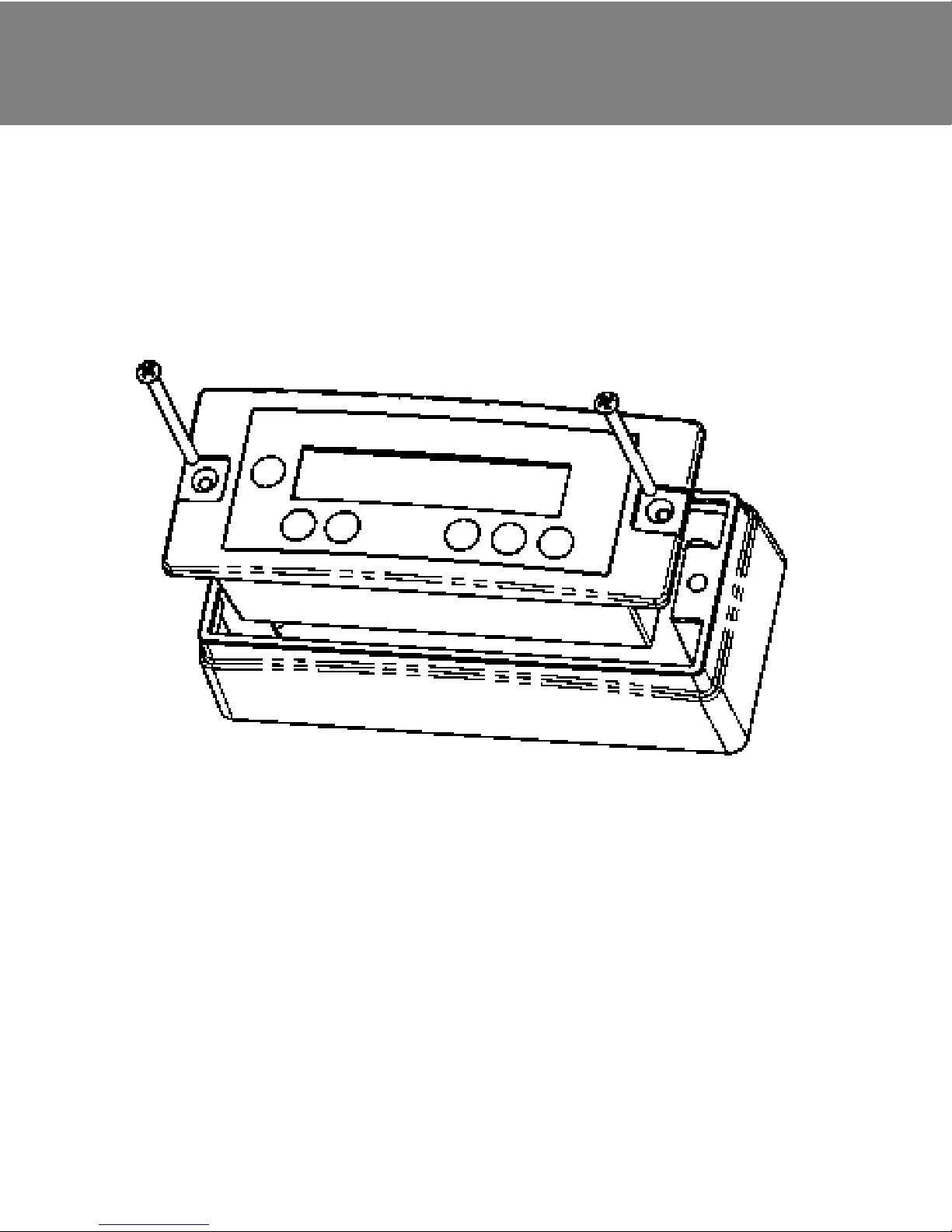
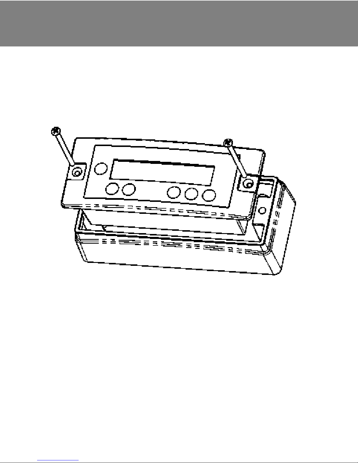
Verwendung als Aufbaugerät:
Bei jedem FOX-MD1 ist zusätzlich zum Einbaugehäuse auch ein
Rahmen für die Aufbaumontage enthalten. Die folgende
Explosionszeichnung verdeutlicht die Montageweise.
Verwendung als Einbaugerät:
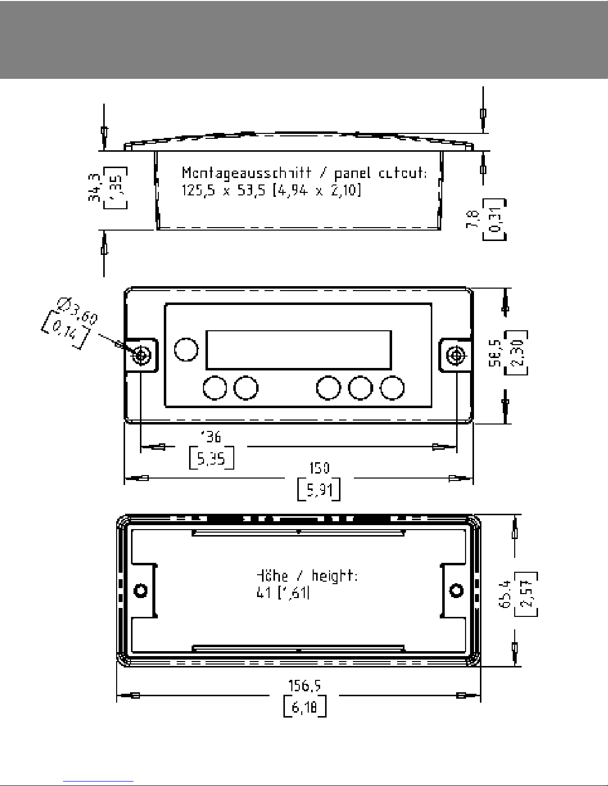
Bei Verwendung als Einbaugerät muss eine Aussparung in der Größe
von 125,5 x 53,5 mm geschaffen werden. Die minimal benötigte
Einbautiefe beträgt dann 40 mm.
Ablauf der Montage:
1. Anschlusskabel in FOX-MD1 einstecken.
2. Gerät in Aussparung oder in Aufbaugehäuse setzen
und mit 2 Schrauben fixieren.
3. Abdeckung des Stecksockels am FOX-Gerät vorsichtig
entfernen.
ACHTUNG: Nicht die dahinter liegende Buchse beschädigen!
4. Anschlusskabel in das FOX-Gerät einstecken.
4
DE | GB | FR | IT | ES | GR | SE | NL

Montage und Inbetriebnahme
3 |
Der FOX-MD1 beginnt zu arbeiten, wenn der Stecker am FOX-MD1
und am zweiten FOX-Gerät eingesteckt ist.
Startsequenz:
· Selbsttest
· Anzeige des Typs und der Versionsnr. des FOX-MD1
· Anzeige des Typs und der Versionsnr. des angeschlossenen
FOX-Geräts
Danach wird die Standardanzeige ausgegeben.
Jetzt können mit der Tastatur die gewünschte Anzeige ausgewählt und
in den Menüs Parameter verändert werden. Je nach angeschlossenem
Gerät zeigt das Menü mehr oder weniger Einträge und Parameter.
Mit Ihrem FOX-Solar-Laderegler haben Sie eine ausführliche
Beschreibung erhalten, in der die Menüs, Anzeigen und Bedienung im
Detail beschrieben werden.
Sollte Ihnen diese Anleitung nicht mehr vorliegen, können Sie diese
jederzeit von der WebSite www.sunware.de herunterladen oder bei
Ihrem Händler anfordern.
5
Technische Daten
4 |
Technische Daten:
Eigenstrombedarf: 3,0 mA
mit Hintergrundbeleuchtung 50 mA, 10 sec.
Stecksockel: RJ45
Kabeltyp: Ethernet CAT5
max. Kabellänge: 10m
Sockel-Pinbelegung: Pin 1 +5V
Pin 2 Ground
Pin 3 TX
Pin 4 RX
Gewicht: 120g
Gewicht inkl. Verpackung 500g
Der FOX-MD1 enthält keine Bauteile, die eingestellt oder
repariert werden können. Durch Öffnen des Gehäuses erlischt
die Gewährleistung.
Merkmal Wert/Einheit
Umgebungsbedingungen -25°C ... +50°C, nicht tauend
Lagerbedingungen -25°C ... +80°C
[ ! ]
6
DE | GB | FR | IT | ES | GR | SE | NL

Hinweise zu Garantieleistungen
Für das an Sie gelieferte Gerät gemäß Rechnung gewährt der
Hersteller ab Kaufdatum eine 24-monatige Garantie. Als Nachweis der
Garantie gilt nur der Kaufbeleg. Alle innerhalb der Garantie
auftretenden Funktionsfehler, die nachweisbar trotz sachgemäßem
Gebrauch entstanden sind, beheben wir bis 24 Monate nach
Kaufdatum kostenlos. Zur Durchführung der Garantiearbeiten muss
das defekte Gerät für den Hersteller kostenlos an das Werk geschickt
werden. Es bleibt unserer Wahl überlassen, ob wir die defekten Teile
reparieren oder austauschen. Ausgetauschte Teile gehen in unser
Eigentum über. Die Kosten für den Rückversand werden vom Kunden
getragen. Durch die Erbringung von Garantieleistungen tritt keine
Verlängerung der ab Kaufdatum eingeräumten Garantiezeit ein. Die
Garantiezeit für Teile, die im Rahmen der Garantie ausgetauscht
werden, läuft mit Ende der Garantiezeit ab.
Von der Garantie ausgenommen sind:
- Schäden, die auf Nichteinhaltung der Hinweise der
Bedienungsanleitung zurückzuführen sind
- Schäden durch Verpolung, Überstrom, Überspannung und
Blitzschlag
- Geräte, die von Kundenseite geöffnet wurden
Durch die Herstellergarantie wird die gesetzliche Gewährleistungspflicht nicht eingeschränkt.
Das Produkt entspricht den Bestimmungen der EMV-Richtline
89/336/EWG. Die vollständige Konformitätserklärung ist einsehbar
unter: wwwsunware.de
Hersteller:
SunWare GmbH & Co KG
Düsseldorfer Str. 80
D-47239 Duisburg www.sunware.de
Gewährleistung
5 |
Irrtümer und Änderungen vorbehalten.
7
6|
Abmessungen
8
DE | GB | FR | IT | ES | GR | SE | NL
Package contents: 1 x FOX-MD1
1 x mounting frame
2 x screws for built-in version (short)
2 x screws for surface-mounted version (long)
1 x connecting cable, length 5 m
1 x operating instructions
Keyboard
LCD-Display
Mounting screws
Overview
0 |
FOX-MD1
9

Important note
1 |
10
[ ! ]
Please carefully read these operating instructions prior
to the first operation of the FOX-MD1!
Important notes:
· Only connect solar modules as voltage source – do not
connect any wind generators or other charging devices.
· Never connect the connecting cable to your computer,
network units or other devices with RJ45 jack.
· All precautions regarding work with batteries and power
electronics must be observed.
· The display must not get into contact with water or
condensing humidity.
· Only use the display in closed rooms.
· Protect against direct sunlight.
DE | | FR | IT | ES | GR | SE | NLGB

FOX-MD1
Thank you for purchasing the FOX-MD1. Soon after the easy
installation you will not want to be without the large illuminated display
showing all the information about your solar installation.
The FOX-MD1 is a remote display for various FOX units.
The remote display is easily connected to the FOX unit using the
assembled cable.
Due to the large backlit display data can be easily read even in dark
environments. If no key is pressed for 10 sec., the backlight switches
off automatically.
Depending on the unit connected, the FOX-MD1 will display different
data. Parameter values and functional settings can also be changed
for the specific device connected.
The FOX-MD1 can be used as built-in or surface mounted unit.
Therefore, a mounting frame is included with every FOX-MD1.
Only connect the FOX-MD1 to specially developed FOX units which are
specified below:
· Charge controller FOX-220 version 1.0 to 4.5
· Charge controller FOX-320 version 1.0 to 4.5
If the version number of the connected FOX unit is higher than the one
of the FOX-MD1, it is possible that not all the functions of the unit are
supported.
Description
2 |
11
Mounting and operation
3 |
Use as surface-mounted unit:
In addition to the housing for integration, every FOX-MD1 is
additionally supplied with a frame for surface-mounted installation.
The following exploded drawing illustrates the installation steps.
Use as built-in unit:
When using the unit as built-in version, a cut-out of 125.5 x 53.5 mm is
required. Then, the minimum installation depth required is 40 mm.
Installation sequence:
1. Insert connecting cable into the FOX-MD1.
2. Place unit in the cut-out or the surface-mounted housing
and secure with 2 screws.
3. Carefully remove the cover of the receptacle at the
FOX unit.
ATTENTION: Do not damage the socket behind it!
4. Insert connecting cable in the FOX unit.
12
DE | | FR | IT | ES | GR | SE | NLGB

Mounting and operation
3 |
The FOX-MD1 starts operating when the plug is inserted into the
FOX-MD1 and the second FOX unit.
Starting sequence:
· Self-test
· Display of the FOX-MD1 type and version number
· Display of the type and version number of the connected
FOX unit
After this, the standard display will be shown.
Now, you can select the desired display using the keyboard and
change the parameters in the menus. Depending on the connected
unit the menu displays more or fewer entries and parameters.
Together with your FOX solar charging controller, you received an
extensive description with detailed specifications of the menus,
displays and operation.
Should these instructions be no longer available to you, you can
download them from our website www.sunware.de or contact your
dealer who will send them to you.
13

Technical data
4 |
Technical data:
F
Power required by the unit: 3.0 mA
with backlighting 50 mA, 10 sec.
Ambient conditions -25°C ... +50°C, non-thawing
Storage conditions -25°C ... +80°C
Receptacle: RJ45
Type of cable: Ethernet CAT5
max. cable length 10m
Socket pin assignment: Pin 1 +5V
Pin 2 Ground
Pin 3 TX
Pin 4 RX
Weight: 120g
Weight incl. packaging 500g
The FOX-MD1 does not contain any components which can be
adjusted or repaired. Opening the housing will void the warranty.
eature Value/Unit
[ ! ]
14
DE | | FR | IT | ES | GR | SE | NLGB

Notes regarding warranty
For the unit supplied to you according to the invoice, the manufacturer
will assume a warranty of 24 months starting at the purchase date.
The purchase receipt shall be the only proof of warranty. All functional
faults occurring during the warranty period in spite of the proper use
will be remedied free of charge up to 24 months after the purchase
date. The faulty unit must be sent to the manufacturer's work free of
charge for the warranty work to be carried out. It shall be left to our
discretion either to repair or to replace the faulty parts. Replaced parts
will become our property. The customer shall bear the costs for return
delivery. The warranty services rendered shall not extend the warranty
period granted starting from the date of purchase. The warranty period
for parts being replaced under the warranty shall end with the original
warranty period.
The following is excluded from the warranty:
- Damages resulting from nonobservance of the notes in the operating
instructions
- Damages caused by reverse polarity, overcurrent, overvoltage and
lightning
- Units which were opened by the customer
The statutory warranty shall not be limited by the manufacturer's
warranty.
This product complies with the EMC Directive 89/336/EEC. The
complete Declaration of Conformity can be viewed at:
www.sunware.de
Manufacturer:
SunWare GmbH & Co KG
Düsseldorfer Str. 80
D-47239 Duisburg www.sunware.de
Warranty
5 |
Subject to alterations and errors excepted.
15
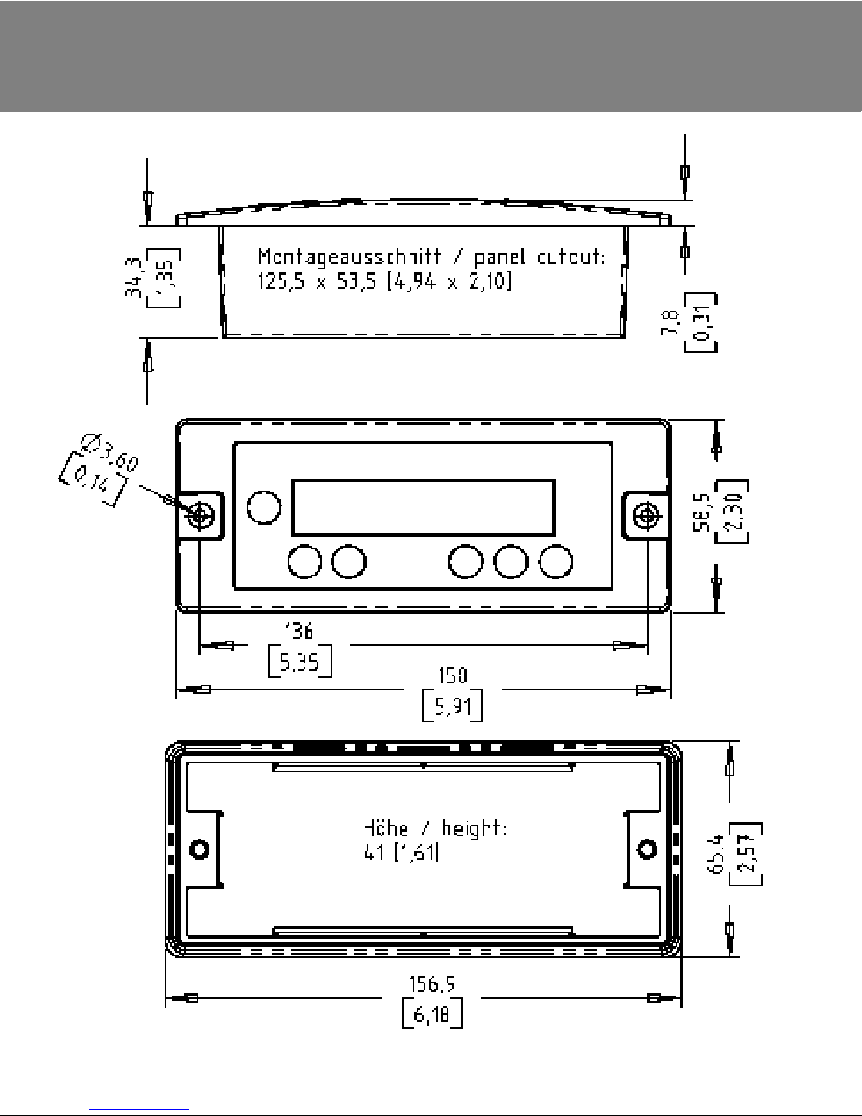
Dimensions
6 |
16
DE | | FR | IT | ES | GR | SE | NLGB
Contenu du paquet : 1 x FOX-MD1
1 x châssis
2 x vis pour la version encastrable (courtes)
2 x vis pour la version apparente (longues)
1 x câble de raccordement, longueur 5 m
1 x guide de l’utilisateur
Clavier
Multi-afficheur numérique
Vis de fixation
Aperçu
0 |
FOX-MD1
17

Consignes d’ordre général
1 |
DE | GB | | IT | ES | GR | SE | NLFR
18
[ ! ]
Avant la mise en service du FOX-MD1, veuillez lire attentivement le
présent guide de l’utilisateur!
Consignes importantes:
· En tant que source de tension, seul le raccordement de panneaux
solaires est permis – jamais des moteurs éoliens, ni d’autres
appareils de charge.
· Ne jamais raccorder le câble de raccordement à votre ordinateur,
ni à des périphériques du réseau et ni à d’autres appareils au
moyen du connecteur Rj45. Une telle action risquerait de détériorer
ces appareils.
· Il est impératif de respecter toutes les mesures de vigilance lors
de travaux sur les accumulateurs et sur l’électronique de
puissance.
· Eviter absolument tout contact de l’afficheur avec l’eau ou
l’humidité de condensation.
· L’afficheur est exclusivement réservé à un usage en intérieur (dans
des locaux fermés).
· Le protéger contre l’ensoleillement direct.

FOX-MD1
Nous sommes heureux que votre choix se soit porté sur le FOX-MD1.
Dès que l’installation simple de l’écran aura été effectuée, vous ne
pourrez plus vous passer de ce grand afficheur éclairé qui visualise
toutes les informations relatives à votre installation solaire.
Le FOX-MD1 est un système de télélecture pour divers appareils FOX.
Le système de télélecture se laisse connecter à l’appareil FOX
simplement au moyen du câble confectionné tout prêt.
Ce grand afficheur rétro-éclairé permet la lecture aisée des données
même dans l’obscurité. Le rétro-éclairage s’éteint automatiquement
après 10 secondes de non-activation d’une touche quelconque.
Les données affichées par le FOX-MD1 diffèrent en fonction de
l’appareil raccordé. Il en est de même pour les valeurs paramétriques
et les réglages de fonctionnement qui se laissent modifier en fonction
de l’appareil raccordé.
Le FOX-MD1 peut être utilisé soit en tant qu’appareil encastrable, soit
en tant qu’appareil apparent. Un châssis est joint, à cet effet, à chaque
FOX-MD1.
Ne raccorder le FOX-MD1 qu’à des appareils FOX spécialement
développés à cet effet et mentionnés ci-après:
· Régulateur de charge FOX-220 version de 1.0 à 4.5
· Régulateur de charge FOX-320 version de 1.0 à 4.5
Si le numéro de la version de l’appareil FOX raccordé est supérieur à
celui du FOX-MD1, les fonctions de l’appareil ne seront
éventuellement pas toutes gérées.
Descriptif
2 |
19
Montage et mise en service
3 |
Utilisation en tant qu’appareil apparent :
En plus du boîtier encastrable, un châssis est aussi fourni avec chaque
FOX-MD1, pour le montage apparent. La vue éclatée représentée cidessous précise la méthode de montage.
Utilisation en tant qu’appareil encastrable :
Une découpe aux dimensions de 125,5 x 53,5 mm est à exécuter pour
l’utilisation en tant qu’appareil encastrable. La profondeur minimale
requise est alors de 40 mm.
Déroulement du montage :
1. Enficher le câble de raccordement dans le FOX-MD1.
2. Placer l’appareil dans la découpe ou dans le boîtier pour
montage apparent et le fixer à l’aide des 2 vis.
3. Enlever avec précaution le couvercle du socle
sur l’appareil FOX.
ATTENTION: Ne pas endommager la prise qui se trouve
derrière !
4. Enficher le câble de raccordement dans l’appareil FOX.
20
DE | GB | | IT | ES | GR | SE | NLFR
 Loading...