

SUNWARD SWL3210, SWL Series Service Manual

Service Manual
Product for the world
SKID-STEER LOADER
HUNAN SUNWARD INTELLIGENT MACHINERY CO., LTD.

SWL3210 Service Manual
1
INDEX
1 INTRODUCTION ....................................................................................................................................... 4
1.1 MODELS AVAILABLE...................................................................................................................... 4
1.2 ABOUT
THIS MANUAL .................................................................................................................... 4
1.3 TREATMENT
OF THIS MANUAL.................................................................................................... 4
1.4 UNITS.................................................................................................................................................. 4
1.5 DEFINITION
OF “LEFT” SIDE AND “RIGHT” SIDE ...................................................................... 4
1.6 PRECONDITION
TO USE THE MACHINE ...................................................................................... 5
1.7 S
IGNALS................................................................................................................................................ 5
2 SECURITY.................................................................................................................................................. 7
2.1 MEANING OF THE SAFETY SIGNS ................................................................................................ 7
2.1.1 GENERAL SIGNS ....................................................................................................................... 7
2.1.2 ACOUSTIC SIGNS.................................................................................................................... 10
2.2 LOCATION
OF THE SAFETY LABELS .........................................................................................11
2.3 GENERAL
PREVENTION ............................................................................................................... 11
2.3.1 GENERAL SAFETY RULES.................................................................................................... 11
2.3.2 CLOTHING AND PERSONAL PROTECTION....................................................................... 12
2.3.3 ENTER AND LEAVE THE MACHINE ................................................................................... 12
2.3.4 PREVENTION OF FIRE TO FUEL AND OIL ......................................................................... 13
2.3.5 PREVENTION OF BURNS....................................................................................................... 14
2.3.6 PREVENTION OF DAMAGE OF WORKING EQUIPMENT ................................................ 14
2.3.7 PREVENTION OF ELECTRIC SHOCK................................................................................... 14
2.3.8 LIMITS OF THE MACHINE .................................................................................................... 15
2.4 MAINTENANCE
PREVENTION..................................................................................................... 15
2.4.1 GENERAL RULES.................................................................................................................... 15
2.4.2 RUNNING THE ENGINE DURING THE MAINTENANCE.................................................. 16
2.4.3 WORKING UNDER THE WORKING EQUIPMENT AND MACHINE ................................ 16
2.4.4 SAFETY RULES FOR HIGH-PRESSURE OIL AND HOSE .................................................. 17
2.4.5 PREVENTION ON THE STARTER AND ALTERNATOR.................................................... 17
2.4.6 PREVENTION OF BATTERY HAZARD ................................................................................ 17
2.4.7 PRECAUTION DURING INFLATING THE TIRES ............................................................... 18
3 GENERAL DESCRIPTION OF THE MACHINE ................................................................................... 19
3.1 DESCRIPTION
OF THE MACHINE ................................................................................................ 19
3.1.1 FRONT VIEW............................................................................................................................ 19
3.1.2 REAR VIEW .............................................................................................................................. 19
3.1.3 MACHINE DISTRIBUTION..................................................................................................... 20
3.2 SPECIFICATION ..............................................................................................................................21
3.2.1 GENERAL DATA ..................................................................................................................... 21
3.2.2 OVERALL DIMENSION .......................................................................................................... 21
3.2.3 ENGINE .....................................................................................................................................22
3.2.4 ELECTRIC SYSTEM ................................................................................................................ 22
3.2.5 PNEUMATIC............................................................................................................................. 23
3.2.6 OILS AND COOLANT.............................................................................................................. 23
3.2.7 CAPACITIES ............................................................................................................................. 23
3.2.8 TORQUE FOR SCREWS ..........................................................................................................24
3.2.9 LUBRICATION POINTS .......................................................................................................... 25
4 HYDRAULIC SYSTEM ........................................................................................................................... 26
4.1 MAIN
TRAVEL PUMP..................................................................................................................... 26
4.1.1 ILLUSTRATION OF MAIN TRAVEL PUMP COMPONENTS ............................................. 26
4.1.2 PIPELINE CONNECTION (FOR TESTING) OF MAIN TRAVEL PUMP............................. 30
4.1.3 SET PRESSURE DATA FOR MAIN TRAVEL PUMP ........................................................... 31
4.2 TRAVEL
MOTOR............................................................................................................................. 33
4.2.1 ILLUSTRATION OF TRAVEL MOTOR MAIN COMPONENTS......................................... 33
4.2.2 PICTURE OF BRAKE OIL PIPES’ CONNECTION................................................................ 35
4.2.3 ROTATION DIRECTION OF TRAVEL MOTOR. .................................................................35
4.2.4 PRESSURE FOR ARRESTING GEAR’S START ................................................................... 35
4.3 WORKING
REAR PUMP ................................................................................................................. 36

SWL3210 Service Manual
2
4.3.1 OUTSIDE VIEW OF GEAR PUMP.......................................................................................... 36
4.3.2 BREAKDOWN DRAWING OF GEAR PUMP ........................................................................37
4.3.3 MANIFOLD VALVE................................................................................................................. 37
4.3.4 OUTSIDE VIEW AND ILLUSTRATION OF MANIFOLD VALVE...................................... 37
4.3.5 SET THE DATA ........................................................................................................................ 38
4.4 BUCKET-LIFT
VALVE.................................................................................................................... 39
4.4.1 THE OUTLINE AND ILLUSTRATION OF BUCKET-LIFT VALVE.................................... 39
4.5
LARGE FLOW CONTROL BLOCK (ONLY FOR LARGE FLOW SYSTEM)................................................. 41
4.5.1 OUTSIDE VIEW AND ILLUSTRATION OF LARGE FLOW CONTROL BLOCK.............. 41
4.5.2 SET THE DATA ........................................................................................................................ 42
4.5.3 OPERATING HANDLE ............................................................................................................ 42
4.5.4 OUTSIDE VIEW AND DATA OF HAND LEVER.................................................................. 42
4.6 PEDAL
OPERATION VALVE .........................................................................................................48
4.7 HYDRAULIC
DIAGRAM ................................................................................................................ 49
5 ELECTRICAL SYSTEM ..........................................................................................................................50
5.1 INSTALLATION SITE 1.......................................................................................................................... 50
5.2
INSTALLATION SITE 2.......................................................................................................................... 51
5.3 D
IAGRAM............................................................................................................................................ 52
5.4 C
IRCUIT DIAGRAM ..............................................................................................................................54
5.4.1 POWER AND ENGINE CIRCUIT............................................................................................ 54
5.4.2 Safety and protection of circuit................................................................................................... 60
5.4.3 MONITOR CIRCUIT................................................................................................................. 63
5.4.4 LAMP AND FLOAT CONTROL CIRCUIT ............................................................................. 65
5.4.5 OPTION CIRCUIT..................................................................................................................... 67
6 TRAVEL SYSTEM................................................................................................................................... 68
6.1 TRAVEL
SYSTEM COMPONENT....................................................................................................... 68
6.1.1 WHEEL SHAFT......................................................................................................................... 69
6.2 P
OWER TRAIN MAINTENANCE .............................................................................................................71
6.2.1 REMOVAL OF THE FRONT WHEEL SHAFT AND REAR WHEEL SHAFT ..................... 71
6.2.2 CLEANING AND INSPECTION .............................................................................................. 75
6.2.3 REPAIR OR REPLACEMENT ................................................................................................. 75
6.2.4 INSTALLATION ....................................................................................................................... 75
7 MAINTENANCE ...................................................................................................................................... 77
7.1 REQUIREMENT
SERVICE.............................................................................................................. 77
7.2 ADVICE
FOR THE MAINTENANCE.............................................................................................. 77
7.3 DESCRIPTION
FOR MACHINE MAINTENANCE ........................................................................ 78
7.3.1 ENGINE DESCRIPTION .......................................................................................................... 78
7.3.2 SAFETY BELT .......................................................................................................................... 78
7.4 MAINTENANCE
PLAN ...................................................................................................................79
7.4.1 BEFORE STARTING ................................................................................................................ 82
7.4.1.1 CHECKING ENGINE OIL LEVEL............................................................................................................... 82
7.4.1.2 CHECKING ENGINE COOLANT LEVEL...................................................................................................82
7.4.1.3 CHECKING ENGINE FUEL LEVEL..................................................................................................................82
7.4.1.3 CHECKING THE HYDRAULIC OIL LEVEL..............................................................................................82
7.4.1.4 CHECKING THE ELECTRIC CABLES....................................................................................................... 82
7.4.1.5 CHECKING THE TIRES ............................................................................................................................... 83
7.4.1.6 CHECKING THE SAFETY BELT ................................................................................................................83
7.4.1.7 CHECKING THE LEAKING OF OIL ........................................................................................................... 83
7.4.1.8 CHECKING THE QUICK COUPLER...........................................................................................................83
7.4.1.10 ECKING THE WATER AND SEDIMENTS SEPARATOR............................................................................. 83
7.4.2 EVERY 50 HOURS OF OPERATION...................................................................................... 83
7.4.2.1 CHECKING THE COOLER PIPES.....................................................................................................................83
7.4.2.2 CHECKING THE COOLANT LEVEL..........................................................................................................84
7.4.2.3 CHECKING THE TIRE PRESSURE............................................................................................................. 84
7.4.2.4 GREASING THE PINS OF BOOM AND CYLINDERS ..............................................................................84
7.4.2.5 CHECKING THE WHEEL NUT DRIVING TORQUE................................................................................. 84
7.4.3 EVERY 100 HOURS OF OPERATION .......................................................................................... 84
7.4.3.1 CLEANING THE TERMINALS OF THE BATTERY........................................................................................84
7.4.3.2 CLEANING THE OIL TANK’S BREATHER ....................................................................................................84
7.4.3.3 CHECKING THE CYLINDER RODS ................................................................................................................ 84
7.4.3.4 GREASING ALL OF PINS..................................................................................................................................85

SWL3210 Service Manual
3
7.4.4 VERY 250 HOURS OF OPERATION ............................................................................................ 85
7.4.4.1 CHECKING THE GEARING CHAIN TENSION............................................................................................... 85
7.4.4.2 ADJUSTING THE CHAIN IF NECESSARY...................................................................................................... 85
7.4.4.3 CHECKING THE FAN BELT.............................................................................................................................85
7.4.4.4 CLEANING THE RADIATOR............................................................................................................................85
7.4.4.5 CHECKING THE OIL LEVEL IN THE GEAR CHAIN..................................................................................... 85
7.4.4.6 CHANGING THE ENGINE OIL.........................................................................................................................86
7.4.4.7 CHANGING THE ENGINE OIL FILTER........................................................................................................... 86
7.4.4.8 CHANGING THE FUEL FILTER.......................................................................................................................86
7.4.4.9 CHECKING THE NUT TORQUE OF THE HYDARULIC MOTOR AND THE HUB HOLDING TO THE
CHASSIS..........................................................................................................................................................................87
7.4.5 EVERY 500 HOURS OF OPERATION .......................................................................................... 88
7.4.5.1 CLAEN THE FUEL-WATER SEPARATOR......................................................................................................88
7.4.5.2 CHECK THE TIGHTENESS OF PUMP FIXING SCREWS..............................................................................88
7.4.5.3 CHECKING THE FLUID LEVEL OF THE BATTERY.....................................................................................88
7.4.5.4 CHANGING THE HYDRAULIC OIL FILTER .................................................................................................. 89
7.4.6 EVERY 1000 HOURS OF OPERATION.................................................................................. 89
7.4.6.1 CHANGING THE OIL IN THE GEAR CHAIN BOX................................................................................... 89
7.4.6.2 CHANGING THE HYDARULIC OIL AND CLEAN THE SUCTION ........................................................89
7.4.6.3 CHANGING THE AIR FILTER ....................................................................................................................90
7.4.6.4 CHECKING THE PUMP’S PRESSURE AND THE VALVE.......................................................................91
7.4.6.5 CHANGING THE HYDRAULIC OIL TANK BREATHER.........................................................................91
7.4.6.6 CHECKING THE TIGHTNESS OF THE CYLINDER HEAD SCREW.......................................................91
7.4.6.7 CHECKING THE LOOSENESS OF THE VALVE....................................................................................... 91
7.4.7 EVERY 2000 HOURS OF OPERATION.................................................................................. 92
7.4.7.1 CHANGING THE COOLANT....................................................................................................................... 92
7.4.7.2 CHECKING THE STARTER AND ALTERNATOR.................................................................................... 92
7.4.8 WHEN REQUIRED ......................................................................................................................... 92
7.4.8.1 DRAINING THE FUEL TANK........................................................................................................................... 92
7.4.9 TROUBLE SHOOTING................................................................................................................... 93
8 INFORMATION OF MANUFACTURER ................................................................................................... 97
SWL3210 Service Manual
4
1 INTRODUCTION
1.1 MODELS AVAILABLE
This manual is special for the SWL series skid-steer loader. A series of skid-steer loaders
“SWL” are developed by HUNAN SUNWARD INTELLIGENT MACHINERY CO., HUNAN
SUNWARD INTELLIGENT MACHINERY CO., LTD own all intelligence property related to
this machine.
1.2 ABOUT THIS MANUAL
This manual contents all the information about the SWL machine. The safety regulations,
description, service and maintenance instructions are included in this manual. HUNAN
SUNWARD INTELLIGENT MACHINERY CO., LTD supply this manual together with the
spare parts book. He provide the user all information
related to the SWL skid-steer loader and all safety
regulations.
For more information, please contact your SWL dealer.
The dealer knows how to get the best performance of
the machine and how to use the machine correctly in
any case.
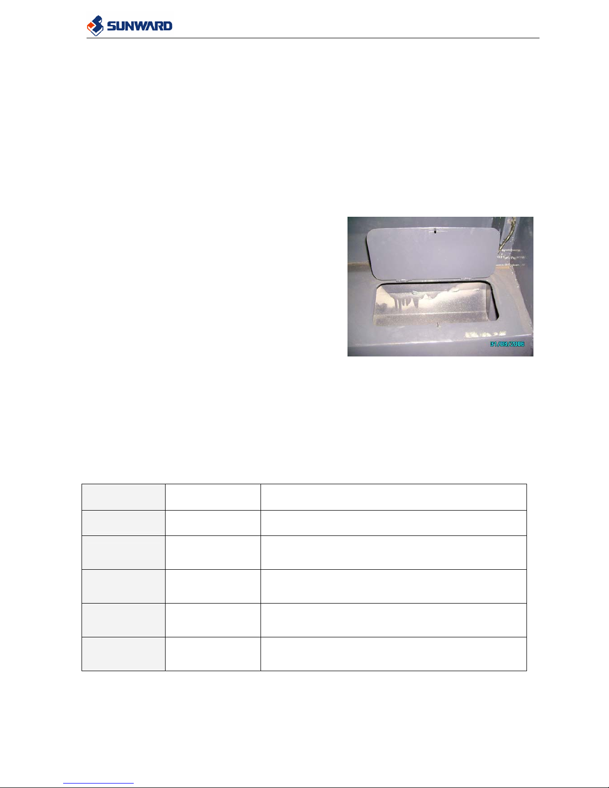
1.3 TREATMENT OF THIS MANUAL
This operation and maintenance manual must be
handled with great care and always kept in the machine,
so that the operator can consult it at any moment. There is a compartment special for operation
manual and spare parts inside cabin. It locates on the behind of the seat. See the right picture.
The operation manual must be always kept in this case.
In case of damage or lose this manual, request to HUNAN SUNWARD INTELLIGENT
MACHINERY CO., LTD or the SWL dealers for a new one.
1.4 UNITS
In this manual we have taken the international unit system. We are using millimeter for distance,
liter for volume, degree for angle, etc.
ITEM UNIT SYMBOL
Distance
Millimeter mm
Volume
Liter L
Angle
Degree
°
Temperature
Celsius degree
°C
Sound
Decibel dB
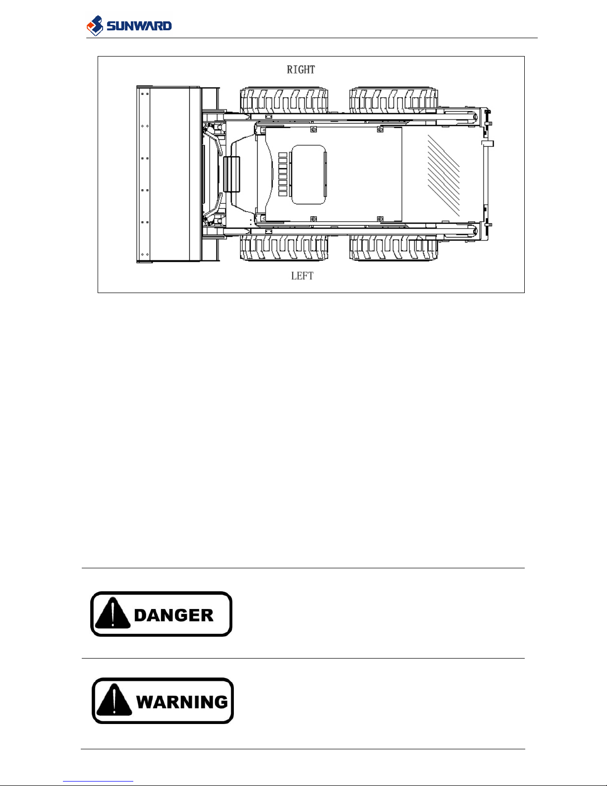
1.5 DEFINITION OF “LEFT” SIDE AND “RIGHT” SIDE
In this manual, “left” and “right” imply your left hand side and right hand side when you are
seated properly in the machine. It is also showed in the picture below.
SWL3210 Service Manual
5
1.6 PRECONDITION TO USE THE MACHINE
z To maintain this skid-steer loader properly and safely, operator must know well about this
machine and have basic experience on using this kind of machine.
z The operator must take special attention on the security recommendation in order to
preserve his security and the security of persons around him.
z Do not work with the machine until you are sure that you can control it properly. Do not
begin a work until you are sure there is no danger for you and for people around you.
z If you have any doubt regarding the safety regulations, please contact your SWL dealer.
1.7 SIGNALS
To help you to maintain machine safely, we have described many safety precautions in this
manual. Also many precaution labels are put on the machine. Many different signal words are
used in the manual and on the labels.
The following signal words are used to inform you that there is a potential hazardous situation
that may lead to personal injury and damage. In this manual and on the precaution labels on the
machine, the following signal words are used to express the level of the potential hazardous.
If not avoided, it has great possibility to lead to serious
injuries or death to the operator (or other persons). It is used
to express the most extreme dangerous situation.
If not avoided, this situation could cause serious injuries
even death.
SWL3210 Service Manual
6
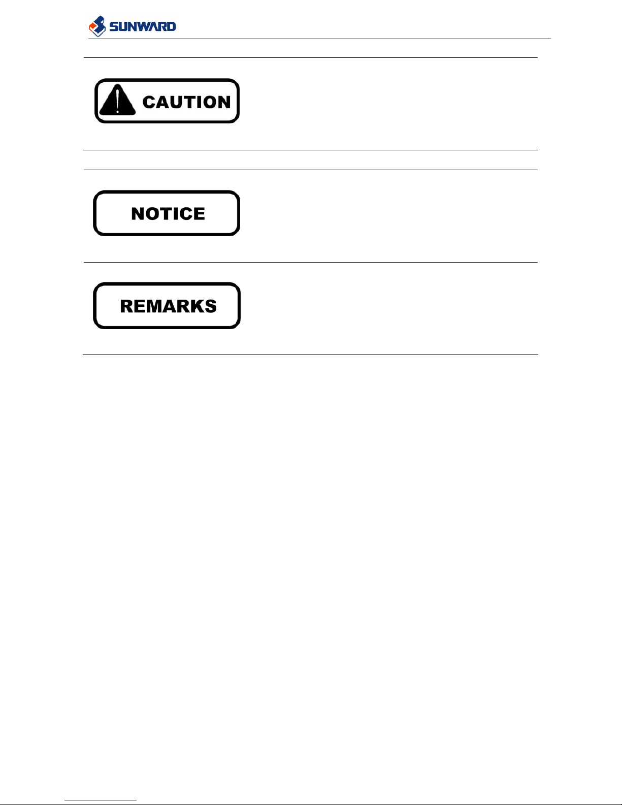
If not avoided, this situation may cause minor or moderate
injury to operator (or other persons) or damage to the
machine.
There are other signal words showed under to indicate precautions that are useful for operator.
It is used for precautions that must be taken to avoid actions
what could shorten the life of the machine.
It is used for information that is extremely useful to know.
The safety message may not include all the possible safety precautions. It is impossible to
describe all the potential hazard may appear during the operation or maintenance. For any
question regarding the safety regulation please contact your dealer.
SWL3210 Service Manual
7
2 SECURITY
This section describes the possible hazards that may appear during the operation and
maintenance of the machine. Authorized additional equipments have their manual given
together with the equipments.
2.1 MEANING OF THE SAFETY SIGNS
Safety precaution labels are fixed to the machine to warn about possible hazards that may cause
personal injuries or even death. They are placed where the possible danger is. Before using the
machine make sure you understand all the security labels. Keep all the labels clean and readable.
Change all the damaged labels.
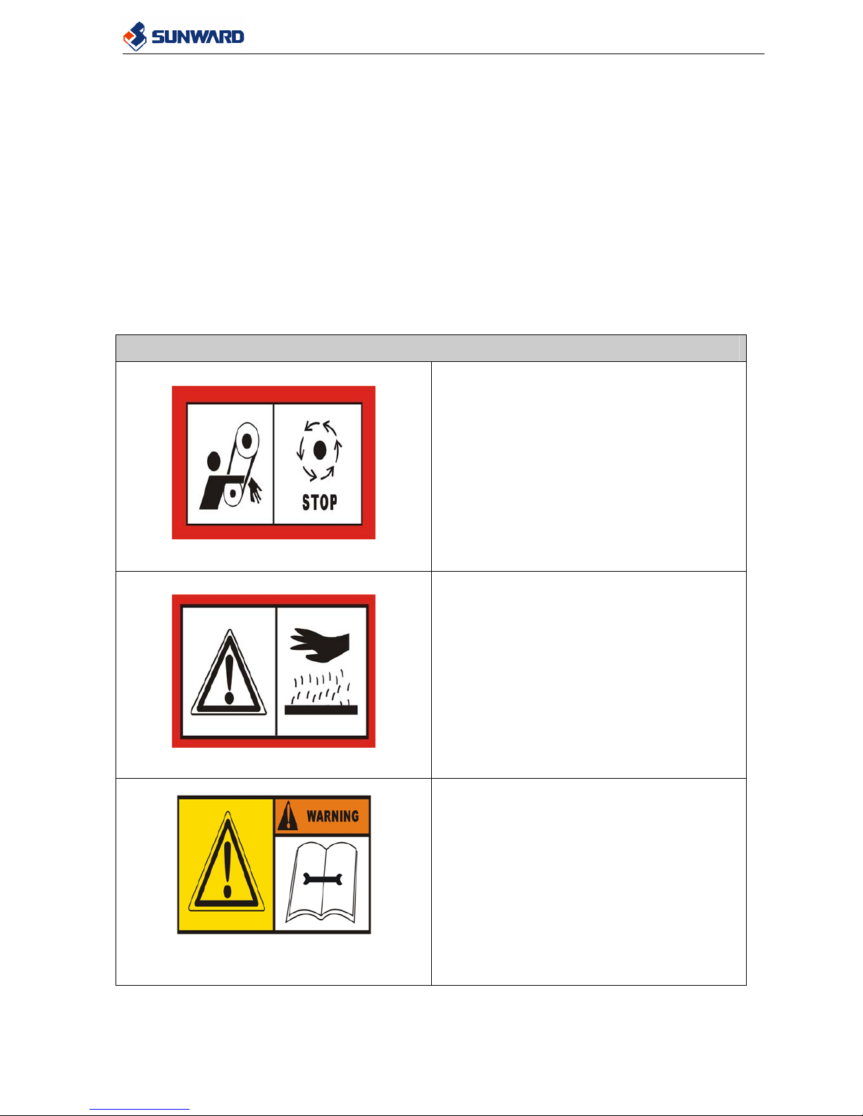
2.1.1 GENERAL SIGNS
The following table shows the different labels fixed on the machine and the respective meanings.
GENERAL LABELS
Moving crawlers, when Entanglements in can
cause serious injury
High temperature
See manual book
SWL3210 Service Manual
8
Note
Float
Tail warning
Oil level
Diesel Oil
SWL3210 Service Manual
9
Oil filter
Drag position
Lifting points
Operation direction
Operation direction
Safety pin for boom
SWL3210 Service Manual
10
Security button
Emergency exit
Engine hood
2.1.2 ACOUSTIC SIGNS
The following table shows the different acoustic labels fixed on the machine and the respective
meaning.
ACOUSTIC LABELS
The max noisy level out of cabin.
The max noisy level in cabin.

SWL3210 Service Manual
11
2.2 LOCATION OF THE SAFETY LABELS
The safety labels were located in striking position.
2.3 GENERAL PREVENTION
2.3.1 GENERAL SAFETY RULES
The following items are extremely important. Operators must read with great care and follow
them while operating and performing maintenance.
z Only authorized and experienced personnel can use or maintain the machine.
z The using and maintenance must be taken follow with the safety rules describe in this
manual.
z Use the machine only when the machine is in good operating condition.
z Don’t use the machine for the tasks exceed its capacity.
z Operate the machine only when the operator is seated correctly in the driving position.
z Before do any maintenance, position the machine on a firm and level surface, lower
working equipments to the ground, engage the safety lock of working equipment, stop the
engine.
z It is forbidden to modify the connections and safety settings of the hydraulic system. Before
do any modification, please consult your dealer. Any unauthorized modification may lead to
serious injury to operator or damage to the machine. HUNAN SUNWARD
INTELLIGENT MACHINERY CO., LTD will not take the responsibility to the result
caused by this kind of unauthorized modification.
z Install only authorized auxiliary equipments. Any additional equipment more than the
authorized auxiliary equipments list in this manual may not perform well even cause
damage to the machine and injury to persons. See the list of authorized auxiliary
equipments.
z Before travel on the road, make sure the lights, signaling and safety device are in good
condition and engage relative safety devices.
z Do not use the machine before read and understand this manual. Any inappropriate use of
this machine could be very dangerous for the operator and the person around the machine.
Many of the accident are caused by insufficient knowledge of the safety regulations
described in this manual.
z It is extremely dangerous operate the machine under the effect of alcohol or drugs. Do not
take alcohol, medicine what makes you sleepy or drugs before or during use the machine.
SWL3210 Service Manual
12
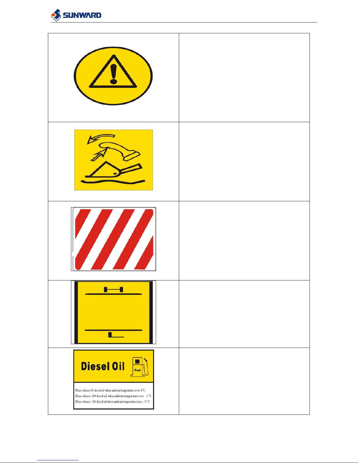
2.3.2 CLOTHING AND PERSONAL PROTECTION
z Inappropriate clothing may lead to injury to the
operator. Please wear in the protective clothing while
operating or performing maintenance such as hardhat,
goggles glasses, mask gloves, safety shoes and
headphones.
z If you have long hair, tie up them before approach the
machine since they can get entangled in the moving
part of the machine and cause serious injuries and
damage.
z When working for 8 hours with a noise exceeding 90
dB, it is necessary to use headphones.
z When working in a special dangerous area, additional
protections could be required according to the
conditions.
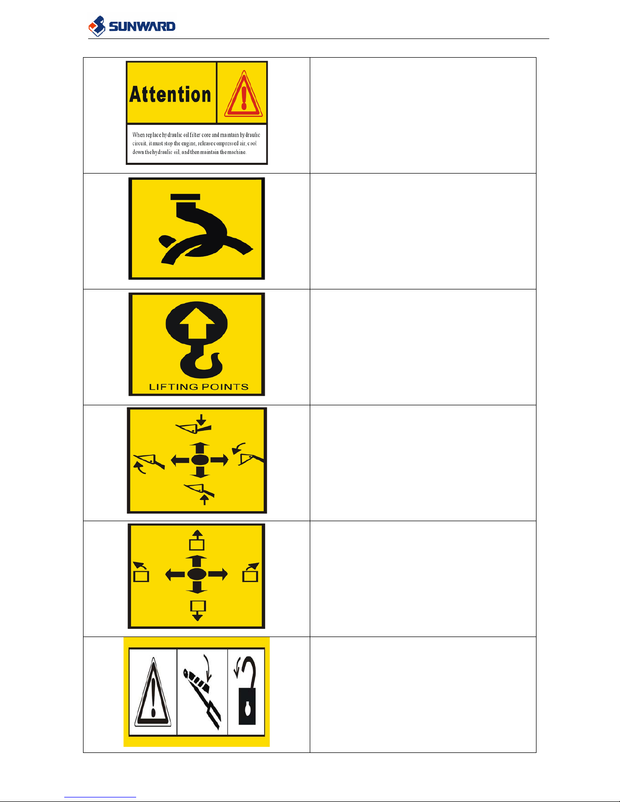
2.3.3 ENTER AND LEAVE THE MACHINE
Use the appropriate footplates and handles showed in the following picture while entering and
leaving the machine.。
z Enter and leave the machine only when the machine is not moving unless it is in
emergency.
z Never hold on the joysticks.
z Use always the appropriate handles while entering and leaving the machine.
z Always be carefully while entering and leaving the machine. Keep your body balance
during the whole processes of entering and leaving the machine.
SWL3210 Service Manual
13
z Before enter and leave the machine, make sure the footplate and handles are not covered
with oil, grease, ice or other slippery matter. In case it happens, clean the slippery matter
carefully immediately.
z Take great care in case the machine is wet. It could be very slippery.
Before leave machine, carry out the following procedures in the sequence.
1) Park the machine in a safe position.
2) Lower the working equipment to the ground.
3) Engage the parking brake.
4) Engage the auxiliary equipment control pedal retainer.
5) Raise the restrain bar to upward.
6) Stop the engine.
2.3.4 PREVENTION OF FIRE TO FUEL AND OIL
z Fuel and oil are easily to cause fire if they meet flame.
z Keep always flame away from the fuel and oil.
z Stop the engine and never smoke during refueling.
z Only do the refilling fuel and oil in the well ventilated areas.
z Close well the safety cap after charge or fuel.
z Do not fill the tanks in order to leave room for the fuel expansion.
z If some fuel or oil is spilled wipe it up immediately.
SWL3210 Service Manual
14
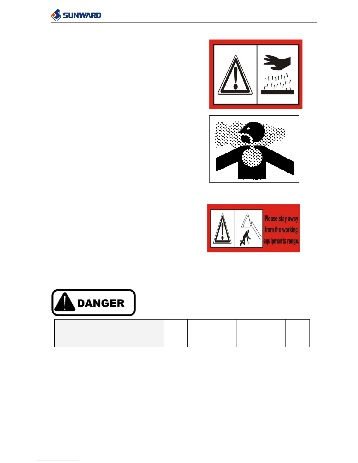
2.3.5 PREVENTION OF BURNS
z After operating for a period, the engine, coolant,
hydraulic oil, engine oil, radiator and pumps are
hot. Do not touch them until they cool down.
z In case of entailing working with hot oil, hot
coolant or hot hydraulic oil, wear gloves, heavy
clothing and safety goggles before do any check
or maintenance.
z Loosen the coolant safety cap slowly when the
coolant is hot to release the residual pressure
inside the tank before open it. If it is hot it may
spurt out and cause serious burns.
z Before checking the coolant level, the hydraulic
oil level and the engine oil level, stop the engine
and wait till they cool down.
2.3.6 PREVENTION OF DAMAGE OF WORKING
EQUIPMENT
z Do not stand in the area that the working
equipment can reach when the machine is operating. It may cause serious injury or even
death.
z Before perform working equipments, the
operator must make sure that nobody is in the
dangerous area that working equipment can
reach.
z Try to lower the working equipment to the
ground every time when you park the machine.
z During maintenance, make sure the equipment is locked correctly before go into the
area under lifted working equipment.
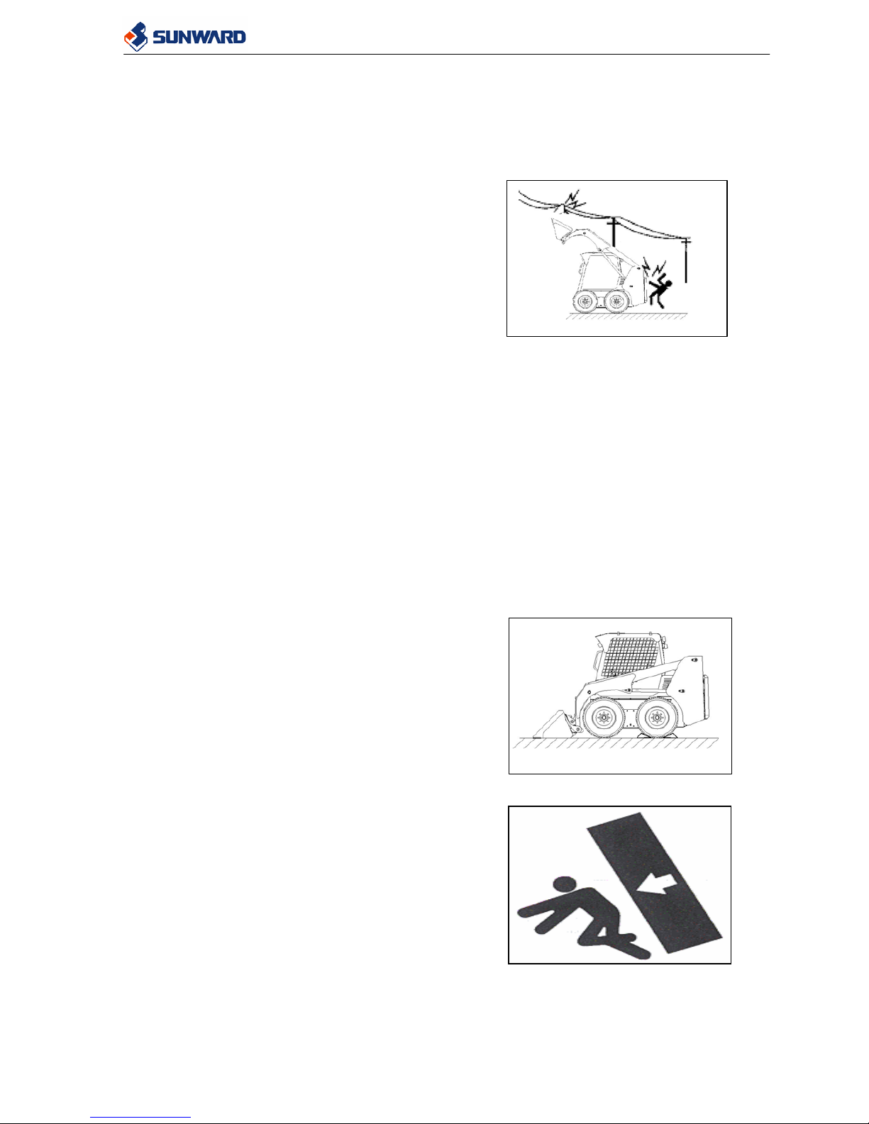
2.3.7 PREVENTION OF ELECTRIC SHOCK
Voltage of Cables (kV)
1.0 6.6 33 66 154 275
Distance must be kept (m)
5.0 5.2 5.5 6.0 8.0 10.0
SWL3210 Service Manual
15
z Do not travel or operate the machine near the electrical cables. On the working sites
where the machine may go close to electrical cables, follow the procedures below.
Otherwise it is possible to get an electric shock, which may cause serious injury even
death.
z Before starting working near the electrical cables,
consult the power company what is the voltage
with the cables and inform the power company
of your coming work. If necessary, ask them to
take actions.
z To prepare for any possible emergencies, wear
rubber shoes and gloves. Prepare all things you
need to call the power company immediately in
case of accident.
z Even going close to the high-voltage cables can cause electric shock. Always maintain a
safe distance (see the table up) from the cables.
z Use a signalman to give warning if the machine approached too close to the electrical
cables.
z If the machine come too close to or entangled with the electrical cables, do not leave the
cabin and let any person approach the machine until the electricity has been shut off.
2.3.8 LIMITS OF THE MACHINE
z This machine has been designed for one operator. More than one passenger on the
machine can be extremely dangerous. Never transport more than one passenger with this
machine.
z Overload could cause serious injuries or even death. Never overload the machine. For
the detail capacity of machine, please refer the section of specification in this manual.
Do not try to get a better efficiency of the
machine by doing any unauthorized change.
2.4 MAINTENANCE PREVENTION
2.4.1 GENERAL RULES
z To do any maintenance position the machine on a
firm and flat surface, rest the equipments on the
ground, engage the security locks, apply the
parking brake and stop the engine. If necessary,
put wedges under wheels to fix the machine.
Before doing the maintenance, place the warning tag
“DO NOT OPERATE” to the joysticks and ignition
switch. Make sure nobody other who is not doing
maintenance together with you operate the machine while
you doing maintenance.
z Only authorized and duly trained personnel can
do the service and repair. Only do the
maintenance that you are certain. If you have any
question, please consult the dealers.
SWL3210 Service Manual
16
z Keep the machine and the ambient clean. Keep the parts and tools in proper place.
z To prevent pollution, never deposit the fuel, oil and grease directly onto the ground. Use
containers to keep the fuel, oil and grease and drain them according to the local
regulations.
2.4.2 RUNNING THE ENGINE DURING THE MAINTENANCE
z If the maintenance must be carried out with
engine running, two workers are necessary. One
worker must always seat in the operator’s seat
and be ready to stop the engine at any time.
z Keep the safety lock in function during the
maintenance operations.
z When the engine is running, don’t touch the
rotating parts. The rotating parts like fan and fan
belt are extremely dangerous because they can
make you get caught. Be careful not to come
close to them.
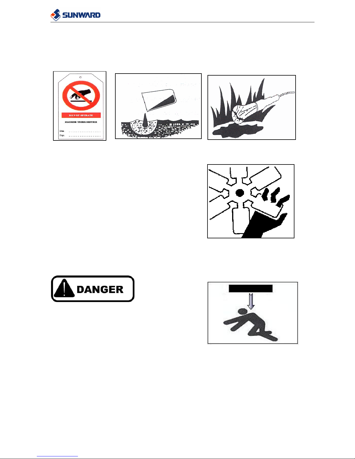
2.4.3 WORKING UNDER THE WORKING EQUIPMENT AND MACHINE
z If it is necessary to carry out service and
maintenance under the working equipment or the
machine, support the equipment and machine
with block and stands strong enough to support
the weight of the working equipment and
machine.
z Lower the working equipment to the ground or the lowest position before working
under the machine.
WRONG
SWL3210 Service Manual
17
2.4.4 SAFETY RULES FOR HIGH-PRESSURE OIL AND HOSE
z The hydraulic system is always under internal pressure. Before do any inspecting or
replacing hoses, always lower the working equipment and make sure that the pressure in
the hydraulic circuit has been released.
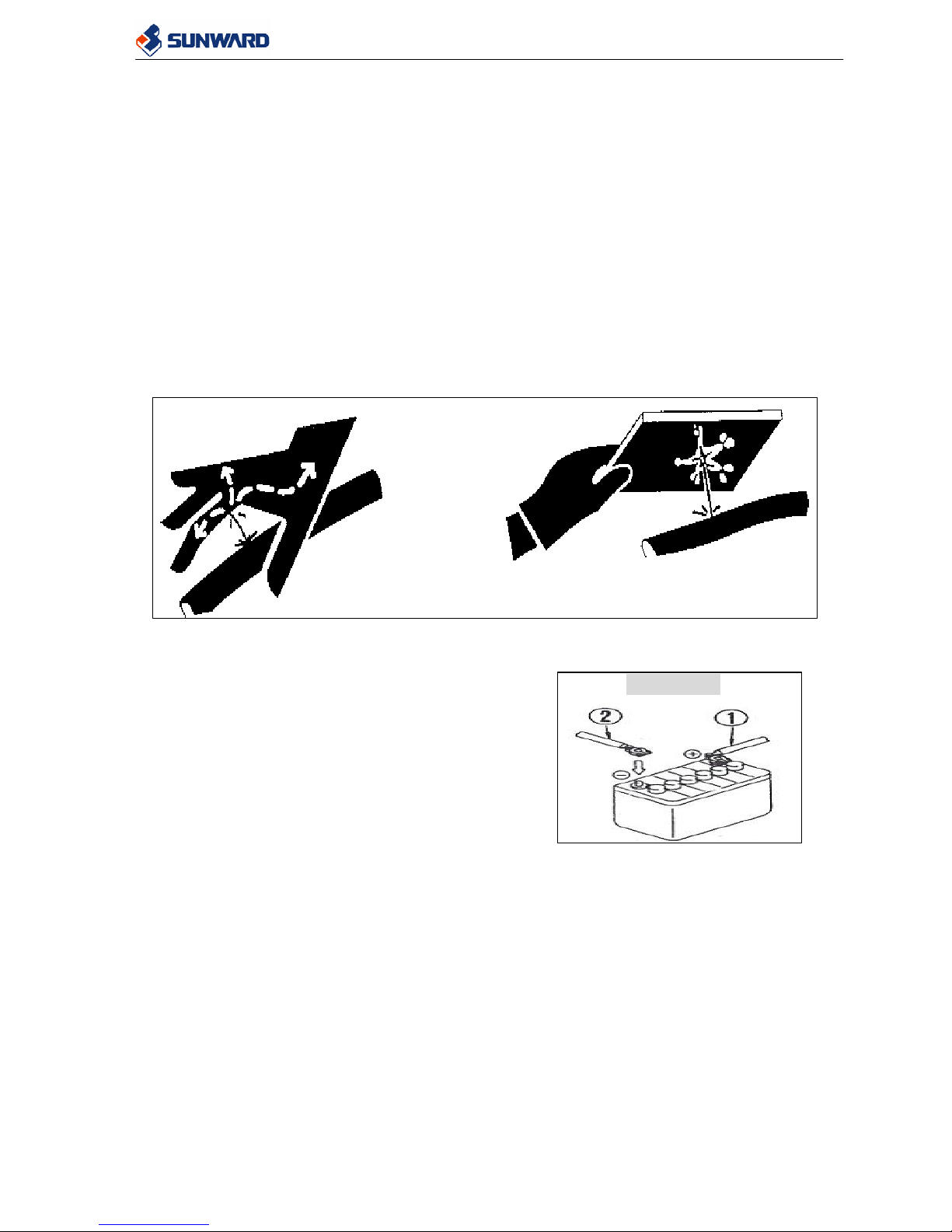
z The high-pressure oil leakage from small holes can penetrate your skin or injury your
eyes. Extreme care must be taken when you are inspecting high-pressure oil leakage.
Wear goggles and thick gloves. Use a piece of cardboard to check oil leakage instead of
your hands.
z Damaged hoses could be extremely dangerous and could cause serious injuries. Change
the damaged hoses and connections as soon as possible.
z If you are hit by a jet of high-pressure oil and suffer injury to your skin and eyes, wash
your skin and eyes with clean water and consult a doctor immediately.
2.4.5 PREVENTION ON THE STARTER AND
ALTERNATOR
z Before doing any check on the electric circuit,
disconnect the battery in order to cut off the
current.
z If some electrical welding has to be done on the
machine, it is necessary to disconnect the battery
and also the alternator.
z Never try to start the engine by manipulating the
connexions of the starter. It will cause sudden machine move. It is very dangerous for
the operators.
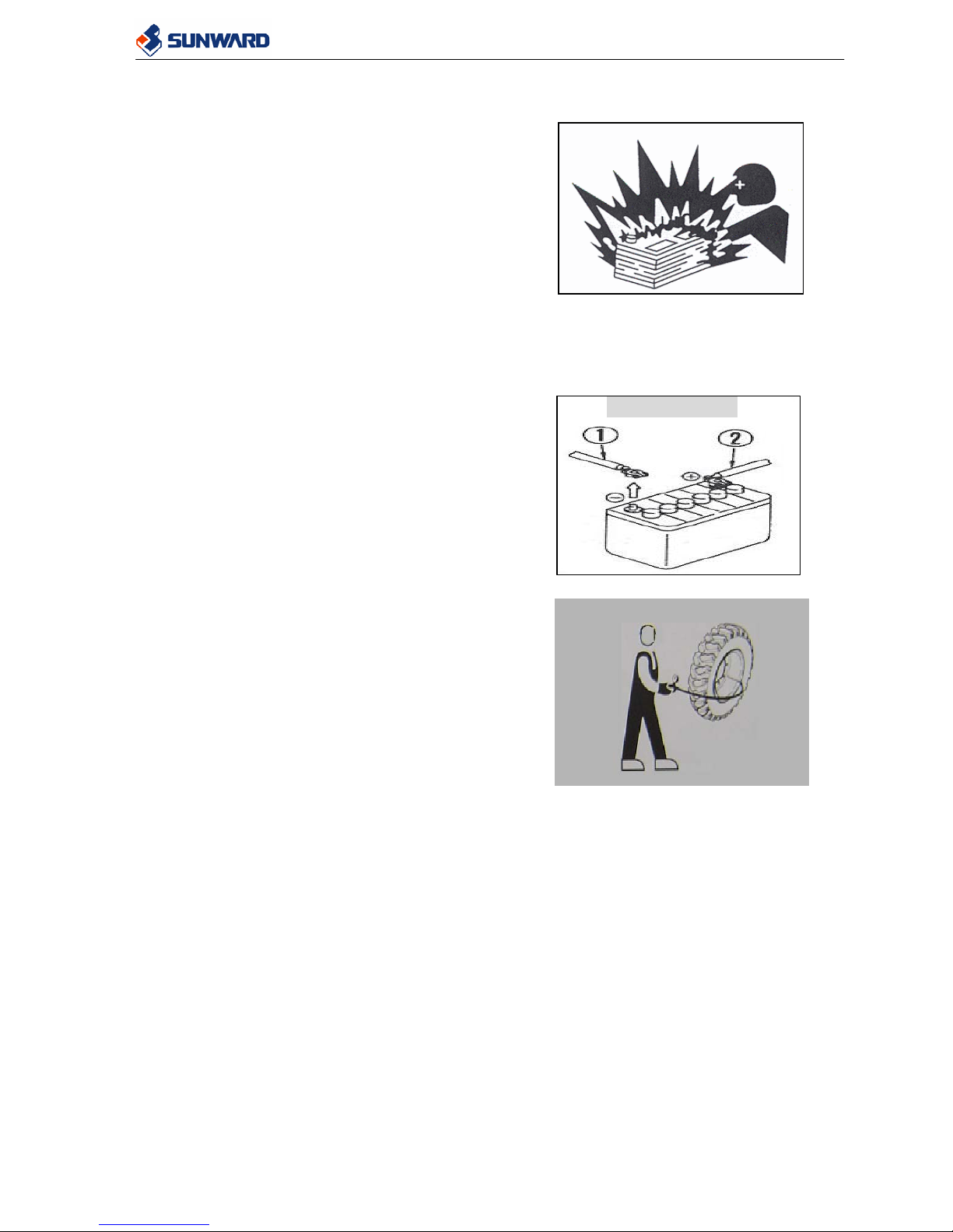
2.4.6 PREVENTION OF BATTERY HAZARD
Battery electrolyte contains sulphuric acid and generates flammable hydrogen gas. The
sulphuric acid is extremely harmful to your body.
Solutions for the accidents:
1) If the electrolyte contact your eyes flush them immediately with plenty water and
contact a doctor immediately. Acid could cause blindness.
2) If some electrolyte contact with your skin, wash immediately with plenty water.
3) If accidentally you ingest some acid, drink a large quantity of milk, eaten eggs or
vegetable oil and call immediately a doctor.
Please always follow with the following precautions:
WRONG
RIGHT
CONNECT
SWL3210 Service Manual
18
z Always wear goggles and gloves when you are working with the battery.
z Stop the engine and remove the key before
working on the battery.
z Never smoke and use any flame near the battery.
z Always tighten the terminals and caps securely.
Loosen terminals or caps may cause fire and
explosion.
z Do not let tools other metal objects make any
contact between battery terminal.
z Disconnect first the negative earth cable (-) and then the other positive cable (+).When
connecting, connect fist the positive cable (+) and then the negative earth cable (-).
z If there is a welding operating on the machine, please disconnect the battery cables
before it.
2.4.7 PRECAUTION DURING INFLATING THE
TIRES
• Take into consideration that tires can burst while
being inflating. Inflate the tires bit by bit.
• For inflating the tires use an air-compressing gun
with extension and a gauge for control the
pressure in the tire.
• Do the maintenance of the tires like described in
the relating item of this manual.
• Do not stand very close to the tire during inflating
the tire and make sure that nobody stands close.
• Follow the recommendation for the pressure
given in the related item of this manual. Make
sure that the tire pressure is the same on both
sides of the machine.
DISCONNECT
SWL3210 Service Manual
19
3 GENERAL DESCRIPTION OF THE MACHINE
3.1 DESCRIPTION OF THE MACHINE
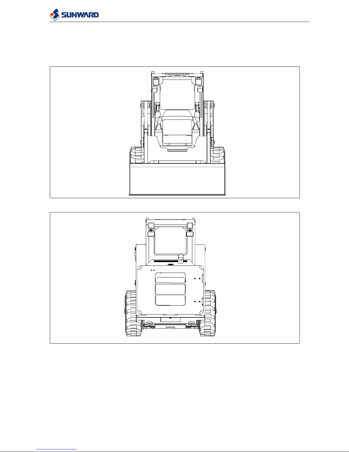
3.1.1 FRONT VIEW
3.1.2 REAR VIEW
SWL3210 Service Manual
20
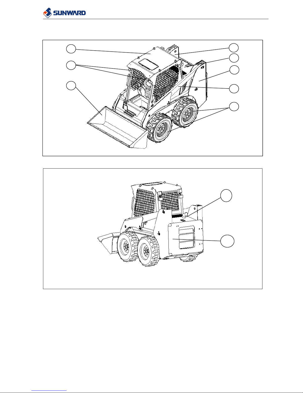
3.1.3 MACHINE DISTRIBUTION
1. Bucket 2.Working lamp
3. Cabin 4.Hydraulic oil tank
5. Engine hood 6. Fuel tank
7. Arm 8. Wheel
9. Exhaust pipe 10. Rear cover
9
10
1
7
2
3
4
5
6
8
SWL3210 Service Manual
21
3.2 SPECIFICATION
3.2.1 GENERAL DATA
ITEM SWL 3210
Operating weight 3250kg
Nominal load 950kg
Tipping Load 1900kg
Bucket volume 0.53m3
Breakout force (lifting cylinder) 2420Kgf
Breakout force (tilting cylinder) 2470Kgf
Max traveling speed 12.6Km/h
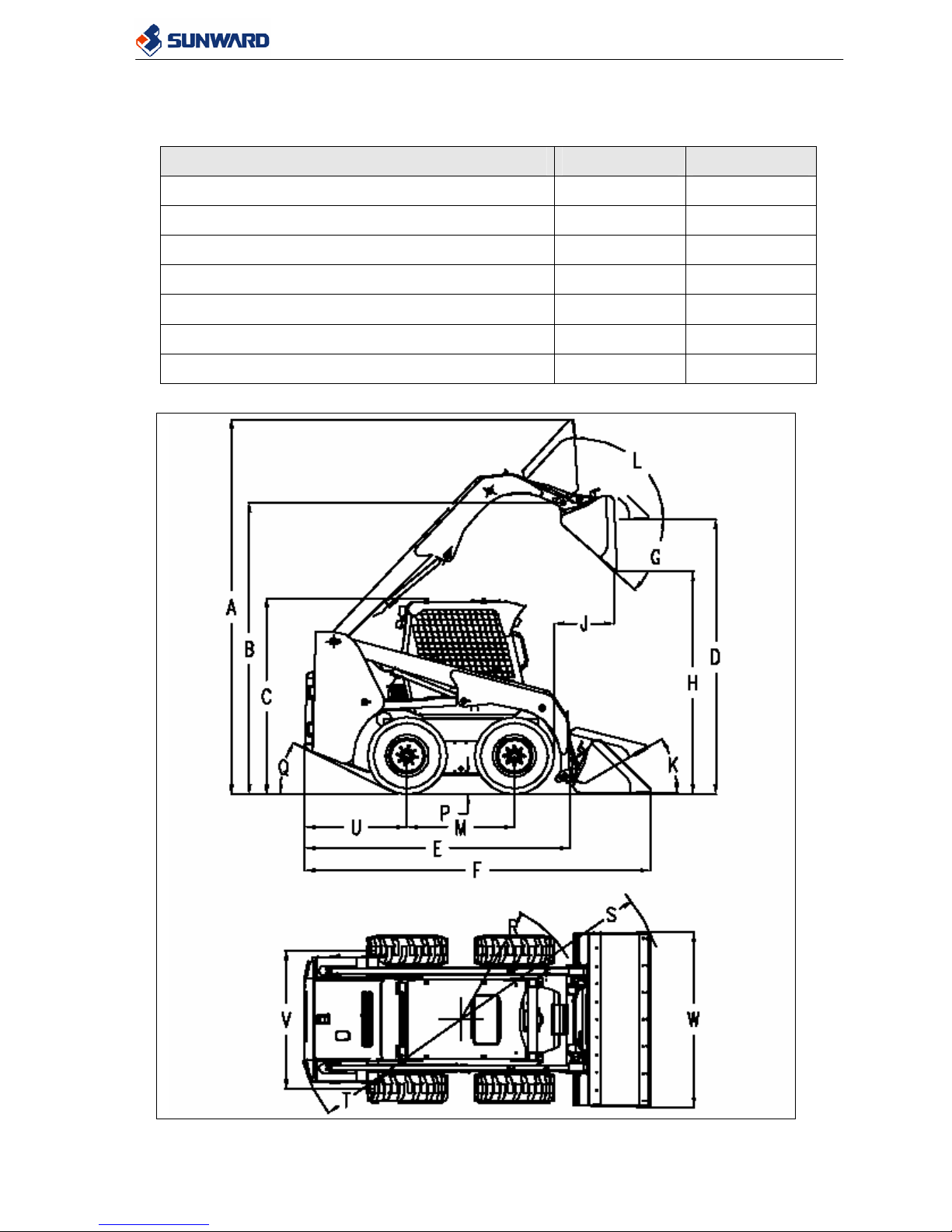
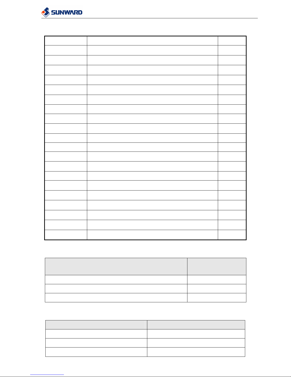
3.2.2 OVERALL DIMENSION
SWL3210 Service Manual
22
Item Specification SWL3210
A Overall operating height
4020 ㎜
B Height to bucket hinge pin
3123 ㎜
C Height to top of cab
2100 ㎜
D Height to bottom of level bucket
2950 ㎜
E Overall length without attachment
2750 ㎜
F Overall length with standard bucket
3590 ㎜
G Dump angle at maximum height 43°
H Dump height
2395 ㎜
J Reach at maximum height
625 ㎜
K Rollback of bucket on ground 30°
L Rollback of bucket at full height 93°
M Wheelbase
1116 ㎜
P Bottom of belly pan
205 ㎜
Q Angle of departure 27°
R Clearance circle front without bucket
1300 ㎜
S Clearance circle front
2180 ㎜
T Clearance circle rear
1700 ㎜
U Rear axle to bumper
1062 ㎜
V Tread width, centerline to centerline
1475 ㎜
W Width with excavating bucket
1880 ㎜
3.2.3 ENGINE
ITEM KUBOTA V3300DI
POWER OUTPUT 54.9Kw
MAX TORQUE 244N-m
ROTATION 2600rpm
3.2.4 ELECTRIC SYSTEM
ITEM SWL 3210
Battery 80Ah or 100Ah
Alternator 12V-45A
Starter motor 12V-3.0A

SWL3210 Service Manual
23
System voltage 12V
Current total 25A
3.2.5 PNEUMATIC
ITEM Pressure
10X16.5 PR10 CHAOYANG 60PSI
12X16.5 PR10 CHAOYANG 60PSI
10X16.5 PR10 MECHILIN 65PSI
12X16.5 PR10 MECHILIN 65PSI
10X16.5 PR10 SOLIDEAL 65PSI
12X16.5 PR10 SOLIDEAL 65PSI
3.2.6 OILS AND COOLANT
z Use only oil and coolant recommended in this manual.
z Use different oils could reduce the efficiency of the machine or even damage the
machine.
OILS, COOLANT AND FUELS SPECIFICATION
Hydraulic Oil
TOTAL AZOLLA ZS46,
MOBIL AW46
Engine Oil
MOBIL DELVAC1330,
ESSO LUBE D-3 10W 30
Engine Coolant
TOTAL MULTIS EP2,
ESSO BEACON EP2
Travelling Mechanism Oil
TOTAL AZOLLA ZS46,
MOBIL AW46
Fuel Diesel Fuel 0#
z Do not mix different kind of oils. If you have oil different from the current oil,
remove all the oil inside the machine.
3.2.7 CAPACITIES
ITEMS CAPACITY (Litre)
Model SWL3210
Hydraulic oil tank 65
Hydraulic system
(Pipes+Tank+Cylinders)
100
Engine coolant 3.5
Engine oil 13.2
Fuel tank 85
Travelling Mechanism 2X15
SWL3210 Service Manual
24
3.2.8 TORQUE FOR SCREWS
Unless other specification, tighten the nuts and bolts according to the torques shown in the
below table. Tighten the goods by the wrenches with gauge.
Thread Diameter (mm) Quality 8.8 Torque (Nm) Quality 10.9 Torque (Nm)
M 6 9~12 13~16
M 8 22~30 30~36
M 10 45~59 65~78
M 12 78~104 110~130
M 14 124~165 180~210
M 16 193~257 280~330
M 18 264~354 380~450
M 20 376~502 540~650
M 22 512~683 740~880
M 24 651~868 940~1120
M 27 952~1269 1400~1650
M 30 1293~1723 1700~2000
When tighten parts of the machine made by steel be careful to not tighten it too strong,
since you could damage this parts.
SWL3210 Service Manual
25
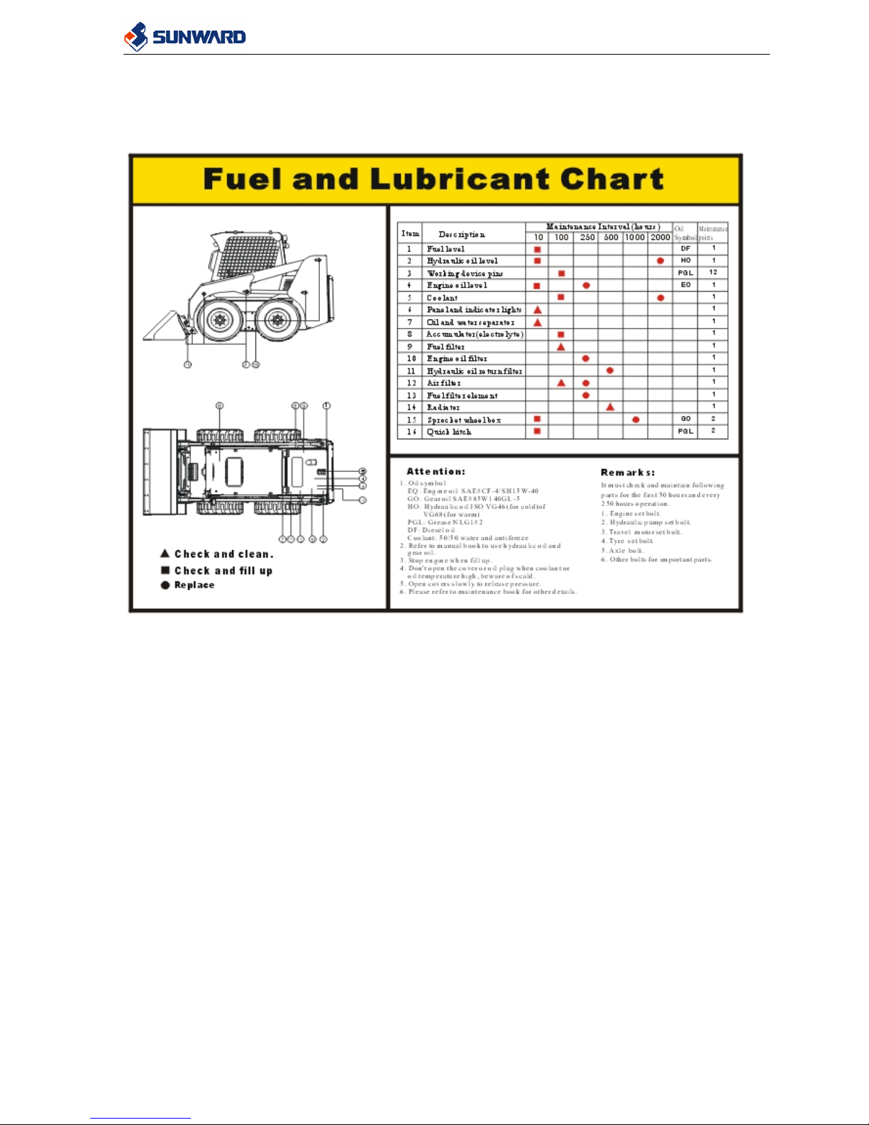
3.2.9 LUBRICATION POINTS
The following drawing shows the main lubrication points.
SWL3210 Service Manual
26
4 HYDRAULIC SYSTEM
4.1 MAIN TRAVEL PUMP
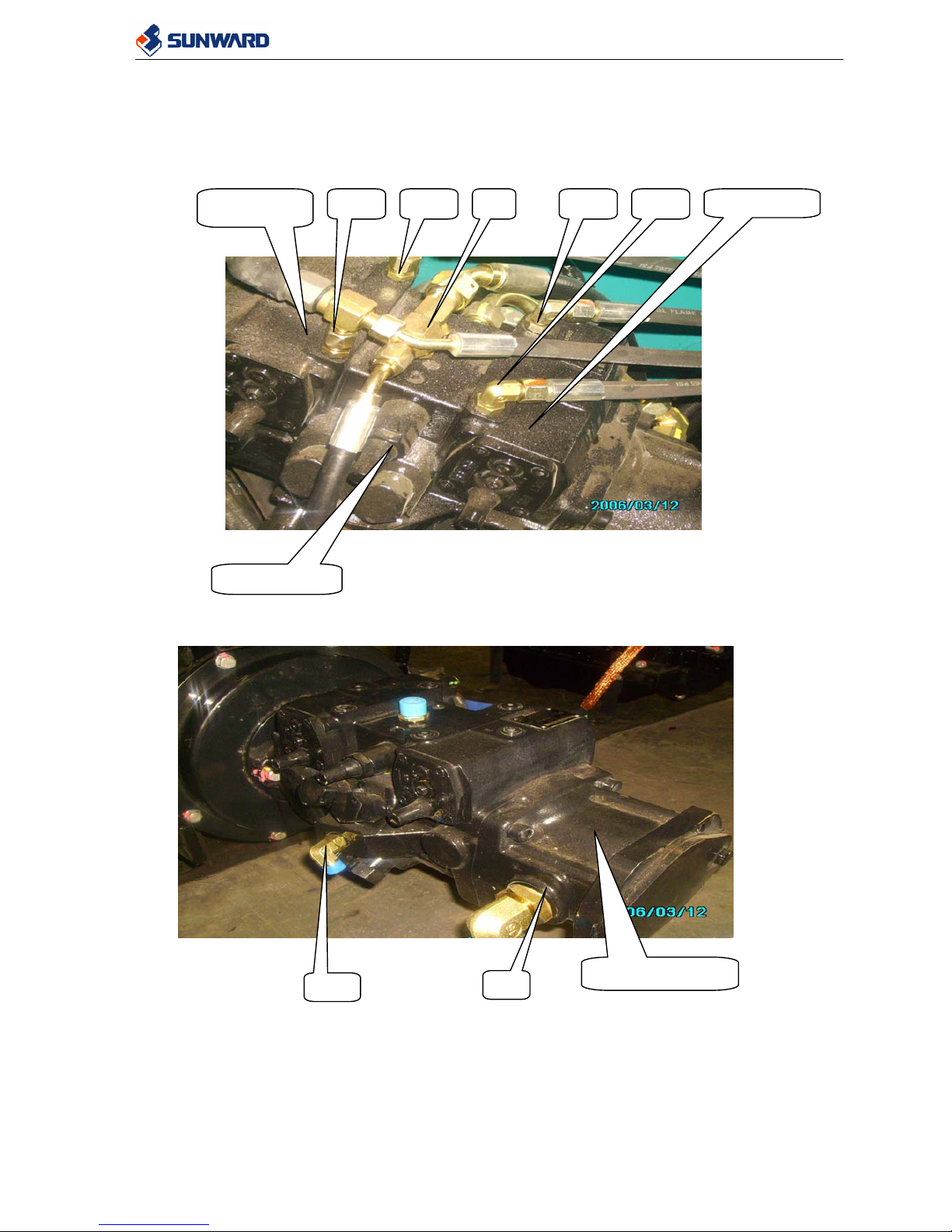
4.1.1 ILLUSTRATION OF MAIN TRAVEL PUMP COMPONENTS
Front pump
Rear pum
p
S
G1
Charge pump
SWL3210 Service Manual
27
Port A of
rear pump
Port A of front
pump
Port B of front
pump
Port B of
rear pump
Port G2 of
charge pump
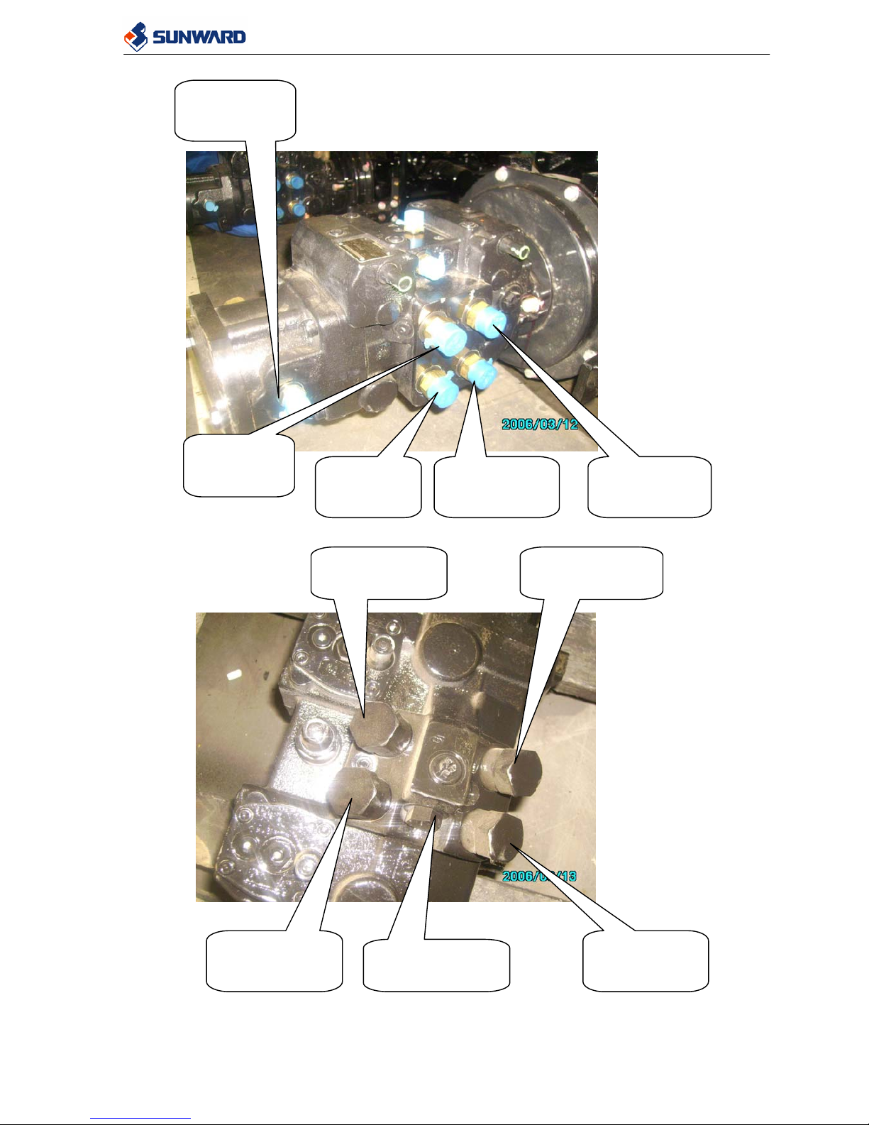
Relief valve of
rear pump port B
Relief valve of
front pump port
B
Relief valve of
front pump
p
ort A
Relief valve of
rear pump port A
Relief valve of
charge pump
SWL3210 Service Manual
28
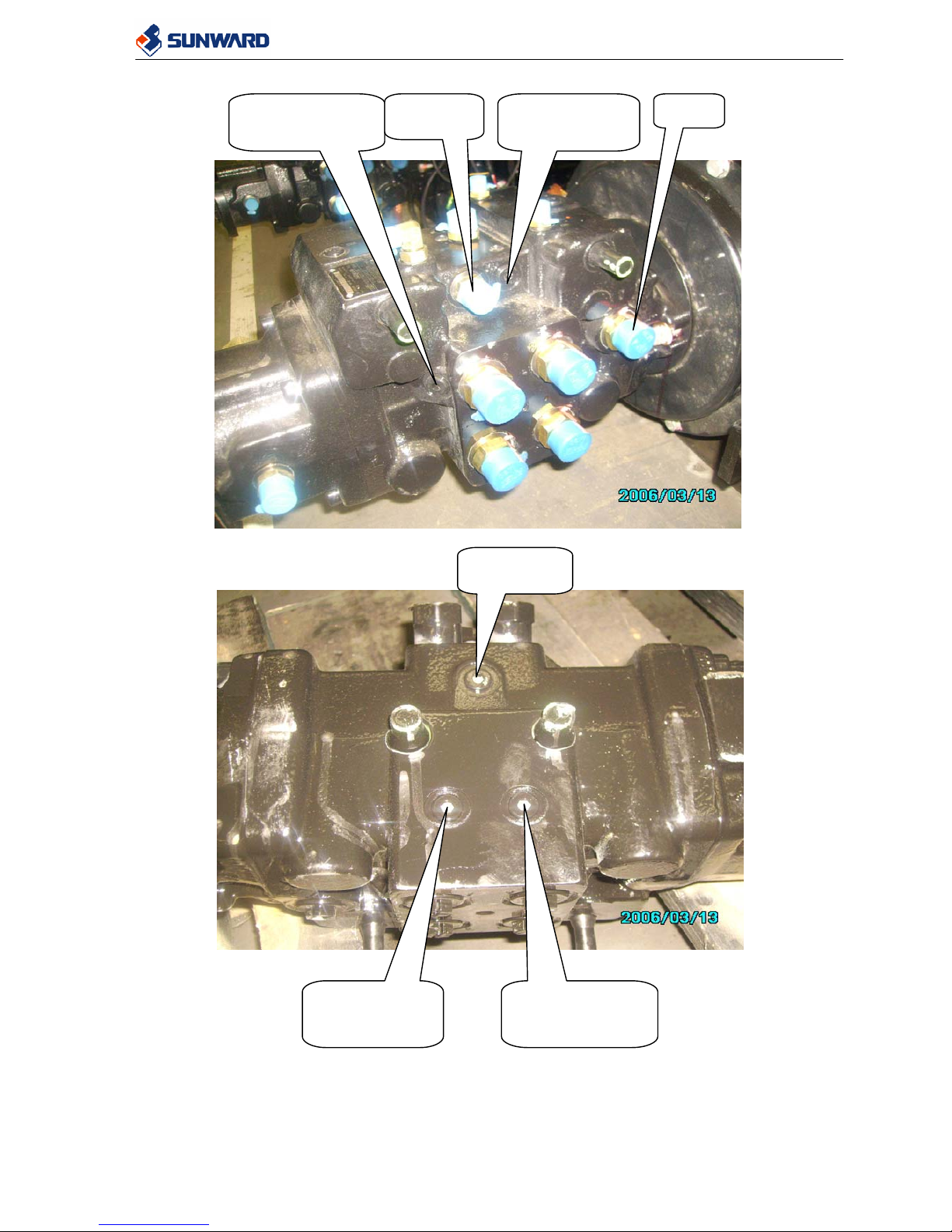
Test port MB of
rear pump B
Test port MB of
front pump B
Port T
Port G
T
est port G
Test port MA
of front pump
A
Test port MA of
rear pump A
SWL3210 Service Manual
29
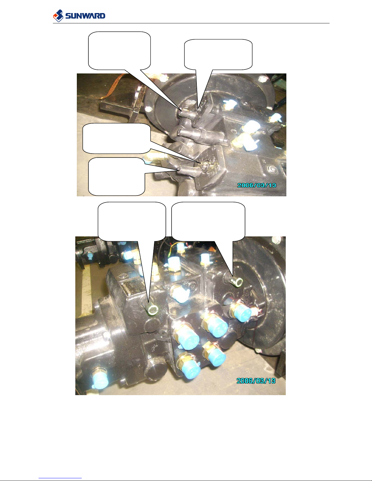
Bolt of max
displacement of
front pump, A
output
Zero displacement
point adjustment
of front pump
Bolt of max
displacement
of rear pump,
A port output
Zero displacement
point adjustment
of rear pump
Bolt of max
displacement of
rear pump, B port
output
Bolt of max
displacement of
front pump, B port
output
 Loading...