

Suntrap Sol-250NG26-32, Sol-315ME-32, Sol-250LPG26-32, Sol-315NG26-32, Sol-315LPG26-32 Installation Instructions And Operating Manual
...Page 1
Copyright © 2012 Suntrap Pty Ltd All rights reserved ABN 87 117 052 856
Solar Hot Water
Installation Instructions
and Owners Manual
AS 2712 Lic 21687
SAI Global
WMKA Lic 21688
SAI Global
This Manual Covers 8 system models:
Electric Boost Models:
Sol-250ME-32: Sol-315ME-32: Sol-250ME-48: Sol-315ME-48
Solarius Range
(modelled to comply with version 12 specifications of ORER requirements)
Gas Boost Models:
Sol-250NG26-32 / Sol-250LPG26-32: Sol-315NG26-32 / Sol-315LPG26-32:
Sol-250NG26-48 / Sol-250LPG26-48: Sol-315NG26-48 / Sol-315LPG26-48
October 2012 issue 5.5
Suntrap Pty Ltd
PO Box 3164
Dural
NSW 2158
Tel: 02 9651 2866
Fax: 02 9652 0481
Plumbers/Installers – Please read this Manual
before attempting the installation of the Suntrap
Solar Hot Water System
All Stainless
Steel Tank
with
10 year
Warranty
All Stainless
Steel Tank
with
10 year
Warranty
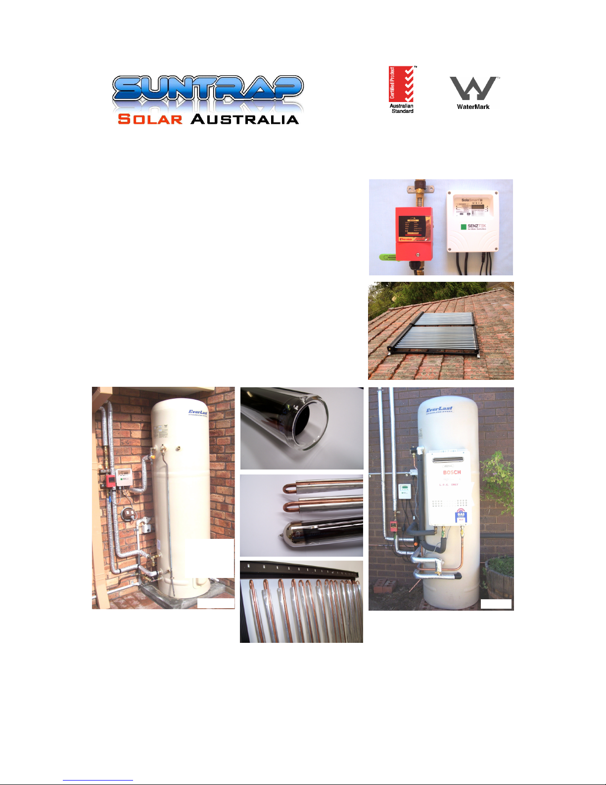
All Systems are available with either
Electric Boost or Gas Boost
Electric Boost
Gas Boost
Page 2
1
Copyright © 2012 Suntrap Pty Ltd All rights reserved ABN 87 117 052 856
Contents
1 Suntrap Solar Hot Water systems – Small-scale Technology Certificates
2 About your Suntrap Solar Hot Water System
3 Suntrap Solar Hot Water Kit – Parts supplied
4 Schematic Diagram of the Suntrap Solar Hot Water System
5 Completed installation views of assembled parts
6 The Suntrap Solar Control Kit
7 Connections to the Suntrap Solar Collectors
8 Connections to the top of the Solar Hot Water Tank
9 Connections to the middle and bottom of the Solar Hot Water Tank
10 The completed Solar Hot Water Tank assembly
11 Check list immediately prior to commissioning System
12 Instructions for assembling and fitting the solar collectors
13 Completing the installation
14 Priming and filling the system
15 Specifications of the Suntrap Evacuated U Tube Solar Collector SLU-1500/16
16 Warranty and Refund Policy
Page 3
2
Copyright © 2012 Suntrap Pty Ltd All rights reserved ABN 87 117 052 856
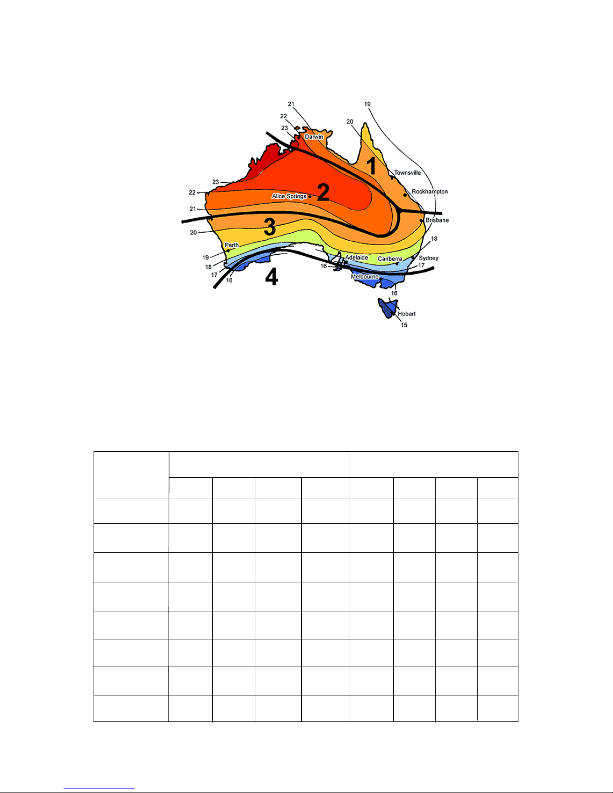
AS/NZS 4234:2007 Climatic Zones
Used in determining the Small-scale Technology Certificates across Australia
1. Small-scale Technology Certificates
Calculated STCs for Suntrap Solarius Solar Hot water Products
The following table presents the calculated STCs and annual energy saving for the different
Suntrap Solarius solar configurations using SLU-1500/16 type evacuated tube collectors
Configuration
Annual Energy Saving (%)
10 Year Small-scale Technology
Certificate Allocation
Zone 1
Zone 2
Zone 3
Zone 4
Zone 1
Zone 2
Zone 3
Zone 4
Sol-250NG26-32 &
Sol-250LPG26-32
Sol-250NG26-48 &
Sol-250LPG26-48
Sol-315NG26-32 &
Sol-315LPG26-32
Sol-315NG26-48 &
Sol-315LPG26-48
Sol-250ME-32
Sol-315ME-32
Sol-250ME-48
Sol-315ME-48
88.4
92.4
72.8
59.3
30
32
29
26
89.8
93.5
89.7
79.8
69.6
42
44
42
37
26
70.4
57.5
38
33
38
41
22
41
30
30
32
38
26
28
68.0
22
39
70.9
74.0
43
60.4
45
43
26
28
26
33
39
80.2
56.9
80.4
56.7
26
88.3
80.1
85.8
68.1
89.2
85.0
71.1
58.1
94.5
91.4
85.4
84.1
93.0
Small-scale Technology Certificates (v.12)
Page 4

3
Copyright © 2012 Suntrap Pty Ltd All rights reserved ABN 87 117 052 856
2. About your Suntrap Solarius Solar Hot Water System
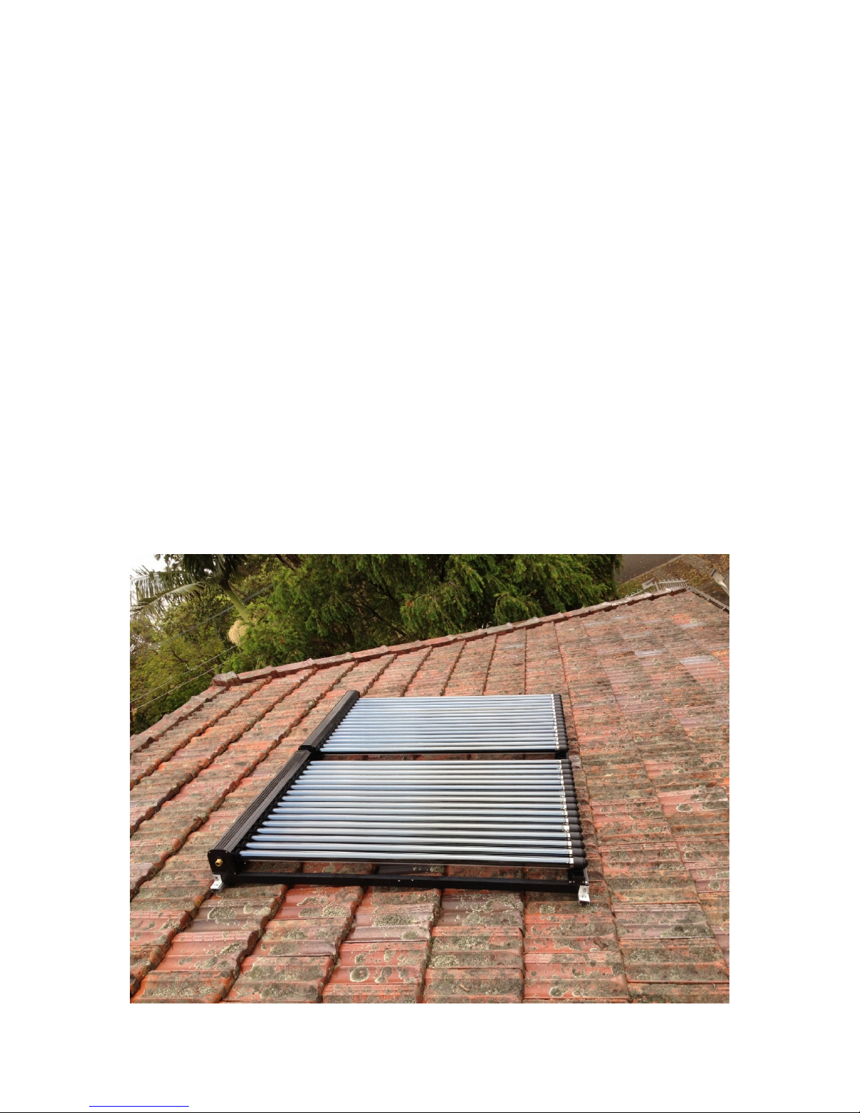
Congratulations for choosing a Suntrap Solar Hot Water System. All the systems are designed to have the Solar Collectors
mounted on the roof, and the Solar tank installed at ground level. Two sizes of Everlast Stainless steel solar hot water tanks are
used and have either an electric or gas boost as supplementary heating sources. Tanks have capacities of 250 litres or 315
litres with either a 3.6 KW heater, or a Bosch 26e gas heater.
The Solar Tanks are suitable for installations either inside or outdoors. Tanks installed inside need to sit in a ‘Safe Tray’. If the area
in which the system is to be installed is subject to freezing conditions, then the hot and cold solar copper pipes must be fully
insulated with closed cell polymer insulation to offer protection against freeze damage.
All electrically boosted Suntrap Solar Hot Water systems are certified to be connected to a dedicated continuous electrical supply.
Risk of scalding
Be aware that the solar hot water temperature can cause scalding. Check the temperature before use. A temperature limiting device
(Tempering Valve) is provided with all Suntrap Solar Hot Water kits and must be fitted to avoid very hot water from the hot taps
(bathrooms, showers etc.)
Temperature adjustment
On electrically boosted systems, the solar tank thermostat maintains the tank temperature during boosting and may be adjusted by a
licensed tradesperson if required. The Solar hot water tank thermostat temperature has been factory set and should not require
adjustment. The Solar hot water tank is also supplied with a Pressure and Temperature Relief valve (PTR 850 Valve) which
must not be tampered with.
The Tempering Valve is required to prevent scalding as solar hot water can be much hotter than just electrically heated water.
The Solar Control Unit will switch the solar pump on to circulate the water when there is a water temperature difference of 8 degrees
centigrade or more between the tank water temperature and the solar collector outlet water temperature (on the roof) and will
switch the pump off when the water temperature difference is 5 degrees centigrade. In the event of cold weather, the pump will
also run to ensure that a minimum water temperature of 4 degrees centigrade is maintained within the solar collectors (to
prevent the water within the solar collectors from freezing).
Safety
The tank is supplied with a Pressure and Temperature Relief valve, a Pressure Limiting Valve, and a thermostat. These devices
must be kept in working order at all times. High temperatures can exist in the solar pipes and precautions must be taken to
avoid young children touching them.
If any power cords or plugs are damaged, then these must be replaced by a licensed electrician.
To turn off the hot water
The water heater boost should remain on unless you plan to be away from home for length of time.
If you need to switch the system off (system close down), switch off the electrical water heater isolating switch (electric element
boost heating), switch off the power to the Solar Control Unit (solar heating), Shut off the cold water-in to the DuoValve (point C)
and close the Shut-off ball valve (point D) on the Solar control kit.
To turn on the water heater
Open the DuoValve (point C),- this allows cold water to enter the solar tank, switch on the Solar Control Unit and open the Shutoff ball valve (point D) on the Solar Control kit, If the solar collectors have been drained then follow the instructions in section 14
of this document (14. Priming and filling the system).
Heater Boost control
Under ideal conditions, your solar hot water will be kept up to temperature by the solar collectors. However on cloudy and
overcast days and during the winter months, the boost heating element inside the solar water tank (electric boost systems) may
be activated to maintain your water temperature. The heating element (immersion heater), must have its own dedicated electrical
supply and must remain connected to the electrical supply at all times.
Water pressure
The water pressure used with this Solar Hot Water system must be a minimum of 200kpa.
Tank Sizes
250 litre 1.62m(h) x 620mm dia. 315 litre 1.98m(h) x 620mm dia.
Solar collector roof space required
2 collectors 2.4m(w) x 1.8m(h) 3 collectors 3.6m(w) x 1.8m(h)
Installers:
All installations must be carried out by licensed plumbers or other authorised persons in accordance with the National
Plumbing and Drainage Code AS3500, and in addition, with any specific requirements of local water authorities.
Please familiarise yourself with all the diagrams and pictures before starting to connect the system together.
Installation instructions begin at section 10.
Some diagrams/pictures are representative only and some pictures are shown before pipe insulation has been fitted for
clarity. To comply with AS2712 certification, the plumbing between the solar hot water tank and the solar collectors
must be installed using 12mm internal pipe diameter with insulation thickness of 19mm on the inlet pipe and 12mm
internal pipe diameter with insulation thickness of 19mm on the outlet pipe, both pipes using insulation material to
ISOpipe insulation standards. For Gas Boosted systems the pipe between the Solar preheat tank and Gas Booster
must use Armaflex 19mm thickness insulation.
Page 5

4
Copyright © 2012 Suntrap Pty Ltd All rights reserved ABN 87 117 052 856
Caring for your system
At the top of the Solar hot water tank there is an 850kpa Pressure and Temperature Relief valve, and it is possible from time to time
that a small amount of water will escape from this valve when the water inside the tank expands during heating periods. This is quite
normal. Every 6 months this valve should be manually operated to ensure that it is in working order. If at any time you believe that
your Suntrap Solar Hot Water system is not functioning correctly, then please give us a call.
Regular Care: Pressure and Temperature Relief (PTR) Valve: This valve is next to the top pipe of the solar tank at point J. The valve
should be checked at regular intervals and replaced every 5 years. To check that the valve is working properly, gently lift the lever
until water flows, then gently let the lever return to its original position. (See Loosing water from the Expansion Control Valve below)
Collector Glass: To assure that maximum efficiency is gained from the Hot water solar system, ensure that the solar collector glass
is kept free of dirt. Hose down the collectors with water and use a soft brush from time to time to keep clean.
Water not hot enough:
This may be caused by the following:
Insufficient sunlight – due to cloudy weather, or cool temperatures during winter – check that the booster heater is working in these
circumstances.
Booster heating not working – check that it is switched on at the electrical distribution panel.
Solar water not hot enough when conditions are good – Check that the solar pump indicator is illuminated on the Solar Control Unit:
Check that the pump is plugged into the Solar Control Unit: Check that the Solar Control Unit is plugged into the electrical supply,
and switched on. Also check that the collectors have unrestricted access to the sun. 2 x solar collectors for a 315 litre tank, with a 3.6
KW boost heater (or a gas booster) is an ideal combination and will provide the solar water temperatures required, under normal
working conditions, if the system is working correctly.
Air in system – Proper circulation of water is not being maintained – Ensure that the air vent is open (point K), then remove (purge)
any air from the system as described in sections 9 and 14. (9. Connections to the middle and bottom of the Solar Tank and (14.
Priming and filling the system)
Excessive use of water – The different Suntrap Solar Hot water System models are designed to cover the requirements of a small to
large number of users, each having their own demand on hot water. A greater demand will cause the water to cool, and longer use of
the booster will be required.
Loosing water from the Pressure and Temperature Relief Valve (Point J) – If thermostat in tank is set too high especially in Summer,
this can result in excessive use of electrical boost heating, leaving the solar heating little to do. This can lead to extremely high
temperatures and water expansion in the solar collectors and can result in excessive water exit from the PTR Valve. Secondary
electric boosting ensures that minimal water temperature is maintained and maximises the benefits and efficiency of solar heating
obtained from the sun. Suntrap systems are certified to use continuous electrical boosting.
Thermostat setting (Electric Boost) – A high tank temperature setting (active during boost times) should be avoided but may be
obtained by the adjustment of the tank thermostat (by a qualified electrician/tradesperson). Please also note that all hot water will
be tempered through the Tempering Valve to prevent scalding from the solar hot water.
Holidays – When away for a period of time, close the system down. Switch off and unplug the solar controller and move the Shut
off ball-valve at point D to the off position, turn off the ‘mains water in’ at the DuoValve at point C, switch off the booster supply. If
freezing conditions are expected while away, leave the solar controller switched on and the Shut off ball-valve (point D) switched
on, so the Solar Hot water system will automatically defrost the Solar collectors as required, otherwise drain the solar collectors
and close the system down as above.
Installation Notes
In the Sydney area the ideal orientation and angle to mount the solar collectors for the winter sun (best for all round
performance) is for the solar collectors to face True North (approx 11 degrees West of Magnetic North) at an angle of 33
degrees. Suntrap U Tube collectors will also work horizontally at an efficiency of 84%, Standard roofs of 26 degrees will provide
an efficiency of approx 97%.
The system is designed to operate with the solar collectors installed on a roof at a height greater than the top of the solar hot
water tank, with the solar hot water tank installed at ground level. Insulated copper pipes to and from the solar collectors must be
direct, and each direction (flow and return) must always run in a continuous rise and fall situation.
The solar collector should be mounted so the Manifold is at the top (higher) level than the bottom of the solar collector.
The tank must be located onto a firm base and sufficient space must be provided around the solar hot water tank for servicing.
Tanks installed inside a property need to sit in suitably drained ‘Safe Tray’.
The Solar Hot Water system uses a different number of solar collectors depending on the system model being installed and the
maximum pipe lengths to and from the solar collectors should not exceed 40 meters. Keep the number of 90 degree bends in the
pipe work to the minimum. The system must be installed with all copper piping (with insulation thickness of 19mm all the way to
the solar collectors and back to the solar hot water tank, and for Gas Boosted systems use insulation thickness of 19mm on the
pipe between the Solar Preheat Tank and Gas Booster).
Warning - Roof assembly and installation of the solar collectors should be undertaken in cool conditions (early
morning) as the fittings can get too hot to handle and could cause injury if touched.
Warning – When purging the system using the purge valve at point G, extreme caution must be taken as water expelled
at this point can be extremely hot. This is best carried out when the solar collectors are cool.
The installation must comply with the requirements of AS/NZS 3000 and AS/NZS 3500.4.
If the tank is to be installed inside a property, then it must be installed in a ‘safe tray’, so that in the event of a leak, the property
will not be damaged by water (AS/NZS 3500.4). Draining of the ‘safe tray’ must also comply with AS/NZS 3500.4.
Page 6
5
Copyright © 2012 Suntrap Pty Ltd All rights reserved ABN 87 117 052 856
For 2 x solar collectors (Sol-250ME-32: Sol-315ME-32: Sol-250NG26-32 / Sol-250LPG26-32: Sol-315NG26-32 / Sol-315LPG26-35)
Part/n – SET232 2 x complete Suntrap evacuated tube Solar Collectors, each with 16 x evacuated glass tubes
Part/n – SSF002 2 x sections of galvanised steel for Roof Frame (top, bottom and 4 x stainless steel straps)
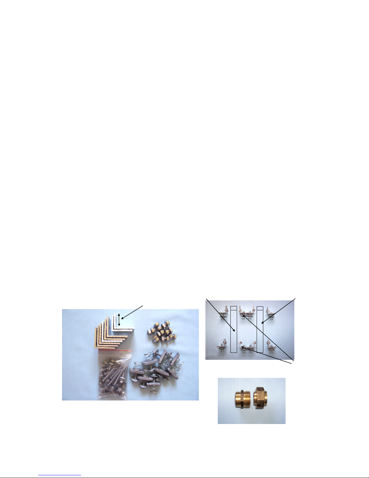
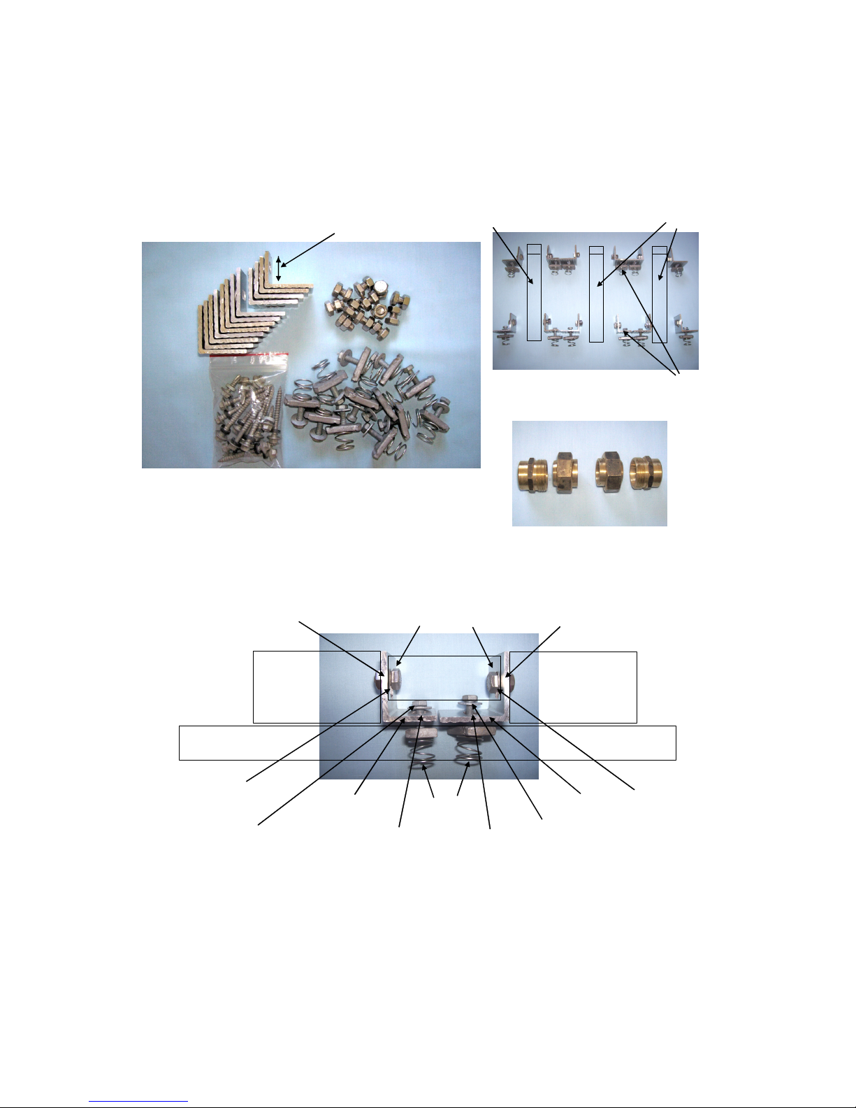
Part/n – MOU002 8 x brackets. 8 x spring clamps, bolts and washers to connect the brackets to the Roof Frame, 8 x nuts
and bolts to connect the brackets to the solar collectors. 4 x screws for attaching the stainless steel straps
to the Roof Frame. 8 x long roof screws for attaching stainless steel straps to the roof rafters.
Part/n – FCS002 1x coupling used to connect the solar collectors together (point N).
FCS002 – Coupling components used
to connect 2 x Solar Collectors together
MOU002 – Bracket arrangement
Solar Collector
Solar Collector
Cut
down
brackets
2 x Cut down brackets
Note: The Cut down brackets are only used between the collectors (one at the top and
one at the bottom to minimise the distance between the collectors for coupling FCS002)
Mains water supply:
The system is fitted with a water pressure limiting valve (connected to the DuoValve at point C). This ensures that the tank is never
under excess pressure. The valve is rated at 500 kpa and must never be changed for a higher rating.
Installation of the Solar Hot Water Tank and Solar Collectors:
The Solar Hot water tank and the Solar Collectors are provided as part of the Suntrap Solar Hot water kit, and all components must
be installed, maintained and operated as per instructions otherwise all warranties are null and void.
3. Suntrap Solarius Solar Hot Water Kits - Parts Supplied
The Suntrap Solarius Solar Hot Water Kits:
All kit components must be used as per supplied. The kit of parts include sub-assemblies which must be fitted complete as supplied.
Suntrap Pty Ltd reserves the right to vary the kit contents and components at its discretion at any time.
There are 8 Suntrap Solarius Kits as follows:
(Please note that there are 16 glass evacuated tubes per solar collector.)
Roof space required for Solar collectors:
2 x solar collectors 2.4 meters wide x 1.8 meters high
3 x solar collectors 3.6 meters wide x 1.8 meters high
Electric Boost Models (All tanks with middle element identified as ME):
Sol-250ME-32: 250 litre solar hot water tank with 2 solar collectors and electric boost-
1620mm (h) x 620mm (dia)
Sol-315ME-32: 315 litre solar hot water tank with 2 solar collectors and electric boost-
1980mm (h) x 620mm (dia)
Sol-250ME-48: 250 litre solar hot water tank with 3 solar collectors and electric boost-
1620mm (h) x 620mm (dia)
Sol-315ME-48: 315 litre solar hot water tank with 3 solar collectors and electric boost-
1980mm (h) x 620mm (dia)
Gas Boost Models:
Sol-250NG26-32 / ST-250LPG26-32: 250 litre solar hot water tank with 2 solar collectors and gas boost-
1620mm (h) x 620mm (dia)
Sol-315NG26-32 / ST-315LPG26-32: 315 litre solar hot water tank with 2 solar collectors and gas boost-
1980mm (h) x 620mm (dia)
Sol-250NG26-48 / ST-250LPG26-48: 250 litre solar hot water tank with 3 solar collectors and gas boost-
1620mm (h) x 620mm (dia)
Sol-315NG26-48 / ST-315LPG26-48: 315 litre solar hot water tank with 3 solar collectors and gas boost-
1980mm (h) x 620mm (dia)
Page 7
6
Copyright © 2012 Suntrap Pty Ltd All rights reserved ABN 87 117 052 856
Left blank for Installer’s Notes:
Collector bracket to Rail fitting – Between Solar Collectors (detail)
Collector
Collecto
r
Mounting Rail
(Part of Frame)
Space for coupling
Cut down collector bracket
Full size collector bracket
Spring Clamps
Collector mounting nuts and bolts
Thin edge to outside
Thin edge to outside
Vertical slot
Vertical slot
Horizontal slot
Horizontal slot
Spring Clamp Bolt and washer
Spring Clamp Bolt and washer
For 3 x solar collectors (Sol-250ME-48: Sol-315ME-48: Sol-250NG26-48 / Sol-250LPG26-48: Sol-315NG26-48 / Sol-315LPG26-48)
Part/n – SET348 3 x complete Suntrap evacuated tube Solar Collectors, each with 16 x evacuated glass tubes
Part/n – SSF003 2 x sections of galvanised steel for Roof Frame (top, bottom and 4 x stainless steel straps)
Part/n – MOU003 12 x brackets. 12 x spring clamps, bolts and washers to connect the brackets to the Roof Frame. 12 x nuts
and bolts to connect the brackets to the solar collectors. 4 x screws for attaching the stainless steel straps
to the Roof Frame. 8 x long roof screws for attaching stainless steel straps to the roof rafters.
Part/n – FCS003 2 x couplings used to connect the solar collectors together (points M and N).
FCS003 – Coupling components used to
Connect the 3 x Solar Collectors together
MOU003 – Bracket arrangement
Solar Collector
Solar Collector
Cut
down
brackets
4 x Cut down brackets
Note: The Cut down brackets are only used between the collectors (one at the top and
one at the bottom to minimise the distance between the collectors for couplings FCS003)
Page 8

7
Copyright © 2012 Suntrap Pty Ltd All rights reserved ABN 87 117 052 856
Part/n – FCV001 1 x Flow Control Valve, 2 x 15mm brass nut and tail connectors, 1 x Check Valve,
Part/n – SHW00E 1 x Solar Tank hot water out assembly (point F), 1 x insulation Boot - Electric Tank
Part/n – SHW00G 1 x Solar Tank hot water out and Gas Booster connection kit
Part/n – SEC002 1 x solar collector sensor cable (to roof) and cable ties
Part/n – SRC00A 1 x Solar recycle outlet assembly, 1 x insulation boot (point P).
Part/n – TEMP01 1 x Solar Rated Tempering Valve, 1 x insulation Boot.
Part/n – BGB26E 1 x Bosch Highflow Gas Boost Heater 26E - (model YE2670RAH - incorporates a Solar Transfer Valve)
BGB26E – Bosch Gas Boost Heater 26E
For Gas Boost Heater Systems
(Gas or LPG)
Gas Boost
Water in
Gas Boosted
Hot Water out
Gas in
X
Y
Z
For Details
of Gas Boost Heater
connections Please see
Gas Schematic
Diagram Section 4
3. Suntrap Solarius Solar Hot Water Kits - Parts Supplied (Cont.)
Part/n – E250ME 1 x 250 litre Everlast stainless steel solar hot water tank with middle element 3.6 KW heating element
or
Part/n – E315ME 1 x 315 litre Everlast stainless steel solar hot water tank with middle element 3.6 KW heating element
or
Part/n – GST250 1 x 250 litre Everlast stainless steel solar hot water tank for Bosch 26e gas boost
or
Part/n – GST315 1 x 315 litre Everlast stainless steel solar hot water tank for Bosch 26e gas boost
Part/n – SCU20A Solar Control Kit, comprising 1 x Solar Control unit, 1 x Solar Pump, 2 x Solar Tank Sensor cables
1 x Ball Valve and Fixings
Part/n – SWI00A Solar water Inlet assembly to collectors
Part/n – CWI20A 1 x Cold water inlet assembly (point H), 1 x insulation Boot
Part/n – SWR00A 1 x Solar Collector Outlet assembly (point k), comprising an Air vent, and a solar collector
temperature receptacle, 1 x insulation Boot
Part/n – DUO00A 1 x DuoValve assembly, 1 x insulation Boot
Part/n – PLV00A 1 x Pressure Limiting Valve 500 kpa assembly, 1 x insulation Boot
Part/n – NRV00A 1 x Solar Return Inlet check valve and a Purge valve (point G)
Part/n – BSR00A 2 x Temperature Sensor Receptacles for the Solar Hot Water Tank
Part/n – PTR850 1 x 850kpa Pressure Temperature Relief valve (Point J)
Page 9

8
Copyright © 2012 Suntrap Pty Ltd All rights reserved ABN 87 117 052 856
SSF002 - Galvanised Steel Frame
and Stainless Steel Roof
straps
SRC00A – Solar Recycle Outlet Connector
(Solar Flow - Point P)
PTR850 – Pressure and
Temperature Relief Valve
(actual model may vary)
Note: This item (PTR850) is
packed behind the electrical
heater access panel in the
Everlast Electric boosted
Solar Tanks
FCV001 – Flow Control Valve and
Check Valve assemblies
Detail of Flow control Valve –
Part of FCV001
SSF003 - Galvanised Steel Frame
and Stainless Steel Roof
straps
SET348 - 3 x Solar Collectors
E315ME - Everlast stainless steel
315 litre Solar tank
SET232 - 2 x Solar Collectors
SHW00E – Solar Tank Hot Water out
connector (connects to Tempering valve)
SHW00G – Gas Boost - Solar Tank Hot Water
out connector and Gas Booster connection kit
BSR00A – Tank Temperature Sensor
Receptacles
SEC002 – Solar Collector Sensor
Cable (to roof) and Cable Ties
Check Valve – Part of FCV001
Page 10

9
Copyright © 2012 Suntrap Pty Ltd All rights reserved ABN 87 117 052 856
3. Suntrap Solar Hot Water Kit - Parts supplied (cont)
SCU20A - Solar Control Kit
CWI20A – Cold Water Inlet assembly, and Insulation boot
SWR00A- Solar Collector outlet assembly with
Temperature Sensor Receptacle
SWI00A Solar Collector inlet assembly
NRV00A – Solar Return Inlet Non-Return Valve with Purge
Valve assembly (Solar hot water in to Solar Tank
)
DUO00A - DuoValve and Insulation
Boot
PLV00A – Mains water inlet Pressure Limiting Valve
Assembly and Insulation Boot
TEMP01 – Solar Rated Tempering Valve
and Insulation Boot
Page 11

10
Copyright © 2012 Suntrap Pty Ltd All rights reserved ABN 87 117 052 856
Schematic Diagram of the Suntrap Solarius Solar Hot Water System (Gas)
Suntrap Pty Ltd
4. Schematic Diagram of the Suntrap Solarius Solar Hot Water System (Electric)
Suntrap Pty Ltd
Solar
Pump
Solar
Control
Unit
Solar
Collector
Solar
Collector
Hot Water Out
to taps
Tank temperature sensors
Pump
Control
Connection
Solar Hot Water Out
Non Return Valve
and Purge Valve
(G)
FEJ
U
H
Solar
temperature
sensor cable
850 kpa Pressure and
Temperature Relief Valve
Solar Tank 500 kpa Pressure Limiting Valve
Air Vent
K LM
Cold Water in
Solar
recycle
Electrical
supply for
heating element
O
Solar Collector outlet connection (Blue or Red dot on Solar Collector)
Solar Collector inlet connection (Blue or Red dot on Solar Collector)
Solar
Collector
N
Either two or three Solar Collectors,
depending on system
Tempering
Valve
D
Domestic electrical supply
DuoValve (on/off and one way)
Lower
temperature
receptacle
Shut-off
Ball Valve
S
T
C
G
Cold Water in
V
Upper temperature
receptacle
Solar Collector temp receptacle
P
Solar Hot
water tank
Flow Control and
Check Valves
R
W
Note: The Blue and Red Dots on the Solar Collectors,
have no significance apart from a means of identification
Solar Hot
Water tank
Solar
Pump
Solar
Control
Unit
Solar
Collector
Solar
Collector
Hot Water Out
to taps
Tank temperature sensors
Pump
Control
Connection
Solar Hot
Water Out
Non Return Valve
and Purge Valve
(G)
F
E
J
G
H
Solar
temperature
sensor cable
850 kpa Pressure and
Temperature Relief Valve
Solar Tank 500 kpa Pressure Limiting Valve
Air Vent
K LM
Cold Water in
Electrical
supply
Cold
Water in
Solar
heating
recycle
Solar
Collector
N
Either two or three Solar Collectors,
depending on system
Lower temperature
receptacle
Bosch Gas Boost Heater (26E)
The Solar Transfer
Valve (STV) is now
incorporated within
the Gas Boost Heater
Tempering Valve
50
70
Bolt Gas Boost Heater r to
Tank if possible
P
D
Solar recycle
DuoValve (on/off and one way)
Shut-off
Ball Valve
C
T
S
U
V
Solar Collector temp receptacle
R
Flow Control and
Check Valves
W
Gas Boost
Water In
Gas Boosted
Hot Water Out
Note: Gas Boost Heater temperature
to be set to 70 degrees centigrade
Upper temperature receptacle
Solar Collector outlet connection (Blue or Red dot on Solar Collector)
Solar Collector inlet connection (Blue or Red dot on Solar Collector)
STV
Y
X
Z
Gas In
Note: The Blue and Red Dots on the Solar Collectors,
have no significance apart from a means of identification
Page 12

11
Copyright © 2012 Suntrap Pty Ltd All rights reserved ABN 87 117 052 856
The Suntrap Solar Control Kit (Gas)
• The Gas Boost Solar Control Kit contains the
following items:
• 1. The Solar Pump
• 2. The Solar Controller Unit
• 3. Ball Valve (Inlet to Solar pump) (Point D)
See Section A above:
• There are two water pipe connections made to the
Solar Recirculation Pump – Flow Control valve and
Check Valve (Point W to Point L) and the Solar
Recycle Tank connection (Point P to Point D) .
• Cold water enters the Solar Hot water tank (Point H)
from the mains water supply through the DuoValve
and the Pressure Limiting Valve (Point C).
• Point D is the inlet to the Solar Recirculation Pump
Ball Valve from the Solar Re-cycle Tank connection
(Point P).
• Point E is the pumped outlet from the Solar Pump.
• Point W is the pumped outlet to the Solar Collector
inlet assembly.
• Point K is the Solar Outlet (return) from the Solar
Collectors.
E
Bottom connections to Gas Tank
Top connections to Gas Tank
P
P
J
F
F
J
H
H
G
G
To Solar Collectors
(via pump)
Cold Water in
From solar Collectors
850 kpa PTR Valve
connection
Solar Hot Water out
Cold Water in
Solar
Hot
Water
Out to
PTR Valve
C
Solar
Transfer
Valve,
Gas boost
Heater and
Tempering
Valve to
Hot Water
taps
U
Tank temp
receptacle
Tank temp
receptacle
U
Flow Control Valve
and Check Valve
assembly
W
Flow
Marked
D
L
K
5. The Suntrap Solar Control Kit (Electric)
• The Solar Control Kit contains the following
items:
• 1. The Solar Pump
• 2. The Solar Controller Unit
• 3. Ball Valve (inlet to solar pump)
• A water pipe connection is made from the bottom
of the Ball Valve (Point D), to the Tank Recycle
connection (Point P).
• The Flow Control Valve and Check Valve are
screwed together and are fitted to the top of the
solar pump, and a water pipe connection is made
from the the top of the Check Valve (Point W) to
the Solar Collector inlet (Point L).
• Point E is the connection point to the Flow Control
Valve.
• Point W is the pumped outlet to the solar
collector.
• Cold water enters the bottom of the Solar hot
water tank at (Point H), via the DuoValve and
Pressure limiting Valve (Point C).
Section A:
• There are 2 electrical connections associated
with the Suntrap Solar Control Kit: The solar
pump is plugged into the socket on the cable
which comes from underneath the Solar Control
Unit. The complete Solar Control Kit is plugged
into a standard 10 amp domestic power socket.
• There is one Solar Collector Sensor (roof) Cable
• There are 2 temperature sensor cables. These
cables are the Solar Tank sensor cables which
must be inserted into the Upper and Lower
Sensor receptacles on the Solar Tank as marked
(at Points U and V).
E
1
E
W
Please set flow as follows:
1.20 ltr/min
Flow Control Valve
and Check Valve
assembly FCV001
Detail of Flow Control Valve
(Part of FCV001)
Check
Valve
Flow
Marked
Flow
Marked
D
Page 13

12
Copyright © 2012 Suntrap Pty Ltd All rights reserved ABN 87 117 052 856
850kpa Pressure and Temperature Relief valve (point J)
Solar return inlet - non-return valve with the purge
valve assembly (point G)
Showing both the Pressure and Temperature Relief valve
(Point J) and solar hot water out connections (Point F) and
(Point S - tempered). (Point T is cold water in to Tempering Valve)
Coupling between the solar collectors (Points M and N)
(Note: actual model may vary)Part/n FCS002, FCS003
Part/n PTR850
Part/n NRV00A
Part/n SHW00E (Point F),TEMP01, PTR850 (Point J) and
2
nd
sensor receptacle used as Blanking Plug (Point V)
J
J
F
T
V
G
R
S
P
To Point T on
Tempering
Valve
H
From
Solar
Collector
Outlet (K)
(Solar Outlet
Return)
To
Solar
Collector
inlet (L)
via Solar
Pump
(Solar
Recycle)
M and N
6. Completed installation views of assembled parts
Solar Control Kit – Solar pump and Solar Control Unit
Also shows Shut-Off Ball Valve fitted
Cold Water Inlet (Point H) and Tank temperature sensor
receptacle (Point U). Also shows connection to
Tempering Valve (attached to Point H).
Solar collector outlet assembly consisting of the Air Vent
Assembly and solar collector temperature sensor receptacle
Note: The temperature sensor must be installed on the outlet
side of the Solar Collector (Point K)
Solar collector inlet assembly
Part/n SCU20A and SOV00A
Part/n CWI20A (H) and BSR00A (U)
Part/n SWR00A
Part/n SWI00A
U
H
To cold
water in on
Tempering
Valve (T)
P
G
Water Flow
K
Water Flow
Page 14

13
Copyright © 2012 Suntrap Pty Ltd All rights reserved ABN 87 117 052 856
7. Connections to the Suntrap Solar Collectors
• Using 19mm thickness insulation, connect a
15mm copper pipe from the middle pipe
connection on the Solar Tank (point G) and
connect to the solar collector outlet (Point K)
• The Air Vent and Solar Temperature ‘collector’
sensor assembly is connected into the solar
collector outlet (Point K)
Important Note:
The Air Vent and Solar Temperature sensor
assembly must be installed on the outlet side of
the Solar Collector (Point K)
• Using 19mm thickness insulation, connect a
15mm copper pipe from the Solar Control Kit
(point E) to the inlet side of the solar
collectors (point L)
Water Flow
Water Flow
L
K
Roof Solar Collector Sensor leads and Cable TiesSolar Control Unit indicator panel
Solar Control Unit showing power plug, socket for pump, and
Solar Tank sensor leads (for Upper and Lower tank positions)
Underside of Solar Control Unit showing temperature
sensor leads and solar collector (roof) sensor plug position
6. Completed views of assembled parts (cont)
Access to optional connections to clean relay contacts
for timed 11pm to 6am boost element control.
(See Note in Section 13, page 19)
Page 15

14
Copyright © 2012 Suntrap Pty Ltd All rights reserved ABN 87 117 052 856
8. Connections to the top of the Solar Hot Water Tank
• The top picture shows the top pipe
connection on the solar tank (Point F) which
is the Hot water outlet to the Tempering
Valve.
• The Tempering Valve (Point S) – Tempered
Hot water out to hot taps.
• The cold water input to the Tempering Valve
enters at (Point T) from Point H on the solar
hot water tank.
• The 850kpa Pressure and Temperature
Relief valve (fitted at Point J) – is supplied
as part of the kit from Suntrap.
• Fit the 2ndtemperature sensor receptacle to
point V (part of P/N BSR00A) – used as a
blanking plug as this port is not used.
• The bottom picture shows the Solar Hot
water out connector and the Gas Booster
connection kit.
Connections to the top of the Electric boost tank
SHW00G – Solar hot water out connector and
Gas Booster connection kit
F
T
J
F
V
S
R
7. Connections to the Suntrap Solar Collectors (cont)
The top picture shows the Solar Collector
inlet connection from the solar pump to the
solar collectors using the connectors
supplied (Point L).
(Part/n SWI00A)
Part/n SWI00A
Part/n FCS002, FCS003
The lower picture shows the connection
between the solar panels (in ‘series’) using
the supplied Conetite connector (between
Points M and N).
• Use grease on the Conetite connector
seating to aid alignment when tightening
M and N
Water Flow
L
Page 16

15
Copyright © 2012 Suntrap Pty Ltd All rights reserved ABN 87 117 052 856
9. Connections to the middle and bottom of the Solar Tank
G
U
H
P
U
• The middle Solar tank connection (Point G)
Solar hot water in - has a non-return valve fitted.
• Please note the purge valve which must be
used to remove all the air from the solar
collectors and the system during the initial fill
with water. Failure to bleed air from this point
will prevent the solar return water from operating
the non return valve. All air must be expelled at
this point and only water be present, otherwise
the solar water will not circulate between the
solar collectors and the tank. WARNING –
water expelled from this point can be
extremely hot and precautions must be
taken.
• The Solar tank temperature receptacle (Point U)
is where the sensor cable from the Solar Control
unit (front ‘TANK’ socket marked with a blue
label) is placed. Push the sensor head in as far
as it will go. This is the point where the tank
temperature is measured.
• The mains cold water in at the bottom of the
Solar tank connection (H) is made by screwing
the complete assembly into the tank.
• The solar recycle connection (solar flow) is
connected from Point P on the tank to the inlet
to the Solar Pump Shut off Ball Valve (Point D).
H
P
G
10. The completed Solar Hot Water Tank assembly
• The Tank and Solar control kit must be
positioned close together
• The Solar tank must sit on firm and level ground
• If the solar tank is to be installed inside a
building, then the solar tank must sit within a
‘Safe Tray’ which meets the drainage
requirements of AS/NZS 3500.4
Electric Boost:
Solar hot water is piped directly to the domestic
hot water taps (via a Tempering valve). An
electrical connection must be made from the
Solar Hot Water tank to a dedicated electrical
heater supply to provide a ‘boost’ at times when
necessary. (switch off dedicated electrical supply
and then connect to Point O for this purpose).
Electrical cable entry is via an entry provided
to the side of the access cover
Gas Boost:
A separate Gas Boost heater must be installed
on the hot water outlet from the solar tank. For
maximum operational efficiency the Gas Boost
heater (incorporating the Solar Transfer Valve
(STV)) should be mounted as close as possible
to the solar tank to minimise the effect of ‘dead
leg’ water (water that goes cold in the pipes
between the Tank and Gas Boost heater) and to
prevent unnecessary activation of the Gas Boost
heater.
A Tempering valve is also required to be fitted,
prior to the hot water going to the domestic hot
water taps.
Set the Gas Boost heater temperature to 70
degrees centigrade.
Electrical connection for Boost (Point O)
Cable
Entry
point
Part/n E315ME
O
Page 17

16
Copyright © 2012 Suntrap Pty Ltd All rights reserved ABN 87 117 052 856
12. Instructions for assembling and fitting the Solar collectors
• Your solar collectors will arrive with the evacuated glass tubes installed. These evacuated glass tubes must be
handled very carefully – Please note that these glass tubes never come into contact with the solar hot water, so if
they ever got broken during the operational life of the solar hot water system, no solar hot water will ever get lost.
They are easy to replace in-situ and do not require the system to be drained. This is because the Suntrap Solar
Hot water system uses U-Tube solar collector technology which fully contains all the solar water within high
pressure copper pipes which run inside the evacuated glass tubes.
As can be seen from the following pictures, the evacuated glass tubes slide into the
collector manifold and are retained by plastic shrouds at the opposite end.
16 U-tubes make up each Solar collector
2 x Solar collectors are shown below
Part/n SET232
3 x Solar collectors are shown below
Part/n SET348
Pre-check list before starting to commission system:
Do not attempt Solar collector installation on a hot day – the Solar collectors and fittings
will be too hot to touch
• Turn off mains water supply valve
• Make sure all connections are tightened
• Make sure all fittings are securely tightened
• Ensure Air vent valve has been opened at least 1 turn (and leave open)
• Understand the importance of correctly purging the system – use of the purge valve at
point G (and the Test plug in the Solar Controller Unit) – if air is left in the system, this
valve will not open and recirculation will not take place: the Solar collectors and pipe
work will pressurise, the pump will be put under strain and damage could result.
WARNING – the water expelled from point G can be extremely hot and
precautions must be taken.
• Ensure that the temperature sensors are correctly placed and secure – again, if these
are not sensing the correct temperatures, the Solar controller will not operate correctly,
which could result in the PTR valve on the tank operating prematurely, and wasting
water. (incorrect temperature detected and solar tank water gets too warm)
• Turn on mains water supply valve. Turn on the cold water in DuoValve
• Turn on Ball Valve at point D (handle in-line with pipe)
• Check diagram below – connections and components to be installed in the order shown
• OK to start commissioning system
Cold water in
DuoValve (on/off and one way)
500kpa Pressure Limiting Valve
Tank cold water in
(point H)
Mains water supply valve
11. Check List immediately prior to commissioning System
Page 18

17
Removing the evacuated glass tubes from the Collector frame
Note the groove on the
front face which is
located into the frame
Push the rear of the evacuated glass
tube retainer upwards
Gently pull the retainer
off the evacuated glass tube
Place the evacuated glass tube retainer to one side
and gently pull the evacuated glass tube out of the
Manifold and over the copper U-Tube.
The evacuated glass tube will slide out of the manifold with the rubber
grommet, When sliding the evacuated glass tube from the manifold
and over the copper U-tube, ensure it is kept in-line with the aluminium
U-Tube copper pipe retainers, so nothing is damaged.
Copyright © 2012 Suntrap Pty Ltd All rights reserved ABN 87 117 052 856
12. Instructions for assembling and fitting the Solar Collectors (cont)
• The top rail is hung the same way with 1575mm from the top edge of the top rail to the top edge of the bottom rail (See C above).
• With all the evacuated glass tubes removed from the collectors, take the collectors to the roof.
•The collector’s must then be mounted to the frame using the spring clamps, bolts, nuts and washers. Push spring into slot and twist (F)
• Note there are left-hand and right-hand brackets supplied. Thinnest edge is always to the outside of the frame
• Position the first collector bracket 20mm from the edge of the bottom rail. Clamp bracket into bottom rail. Bolt collector to bracket.
• Position 2ndcollector next to the 1stcollector and use the coupling to join the tops of the two collectors together. Tighten coupling.
Square and line up both collectors. (Use a full size bracket and a reduced size bracket between each collector as in E below).
Clamp and tighten all brackets to secure 1stand 2ndcollector. A third collector (if supplied) is mounted the same way as the 2
nd
collector (but next to the 2ndcollector)
•Take the evacuated glass tubes to the roof and insert all evacuated glass tubes into the solar collector frames (D)
• The solar collectors are mounted on a Roof Frame which must be installed using the 2 x lengths of galvanised steel (The Frame),
4 x stainless steel straps and screws supplied.
• 4 x ‘L’ shaped brackets attach each collector to the Roof Frame (2 galvanised steel bars)
• The bottom rail of the Roof Frame is then taken to the roof and placed in its lower position. (Hang as A and B below).
The stainless steel straps must be positioned along the frame (two at the top and two at the bottom to line up with the roof rafters
under the roof tiles on which to secure the Frame (assuming a tiled roof). On each stainless steel strap, screw one screw into the
galvanised steel frame and the other 2 x screws into a roof rafter. Repeat for each stainless steel strap (see over page for details)
B
A
C
D
Thin edge
to outside
Collector
Top Rail
F
Cut down bracket
E
1575mm
Page 19

18
Copyright © 2012 Suntrap Pty Ltd All rights reserved ABN 87 117 052 856
12. Instructions for assembling and fitting the Solar Collectors (cont).
Refitting the Evacuated Glass Tubes
Slide the evacuated glass tubes over the U-Tube copper pipes and aluminium retainers and into the manifold.
Gently ease the grommet into position for a flush seal
The galvanised steel Roof Frame and the stainless steel straps are taken to the roof with no bends in them. When the position of
the Roof Frame has been established, slide a tile up and locate a rafter. Using 2 x of the long roof screws, screw the strap into
position on the rafter so that there will be a sufficient length exposed beyond the normal position of the tile to attach to the roof
frame. Slide the tile back into its normal position. Re-position the Roof Frame, then bend the strap around the Roof Frame to
secure. Repeat this for the other 3 x stainless steel straps.
When the stainless steel straps have been bent around the Roof Frame and the Roof Frame is in its final position, drill through
both the strap and the frame with a 3 mm drill, and screw together. Repeat this for the other 3 x stainless steel straps.
Slide the spring clamps into position, fit collectors and couple them up, and tighten as detailed previously in this Section 12.
To refit the evacuated glass tubes into the
Collectors - Reverse the instructions for
removing the evacuated glass tubes from
the collector frame (see previous page).
Collector
Thin edge of bracket to outside
Top rail
13. Completing the Installation
• Please refer to Schematic Diagram (Section 4) for all reference points:
• Please note that the blue and red dots on each end on the collector have no significance – flow and return can be in
either direction.
• For the Solar Tank Installation - Please refer to the Everlast Owners Manual and Installation Guide.
• Pipe insulation - Use 19mm thickness ISOpipe insulation material on the solar inlet and solar outlet pipes all the way from the
solar hot water tank to the solar collectors and back to the solar hot water tank. For Gas Boosted systems, use Armaflex
material 19mm thickness insulation between the Solar Preheat Tank and the Gas Booster.
• Position the Solar Hot Water tank on firm and level ground near an electrical supply.
• Screw the Shut-off valve to the inlet of the solar pump (Point D) and fit the Flow Control Valve (E) and Check Valve (W)
vertically. Ensure that the arrows point upwards towards collectors on the Flow Control Valve and the Check Valve.
• Position the Solar Control Kit on a wall adjacent to the Solar Hot Water Tank approx 120cm from the ground and within the
‘Tank’ sensor cable length.
• Remove all evacuated glass tubes from the collector frame(s) and put them to one side (see section 12).
• Identify the final position of the solar collectors on the roof.
• Take the Roof Frame (two galvanised steel rails) to the roof (see section 12).
• Attach the Roof Frame to the roof using the 4 x stainless steel straps (see section 12).
If installing the Roof Frame on colorbond (Metal) material, use rubber insulating strip between the Roof Frame and the Roof
• Take the solar collectors to the roof (support the U tubes and aluminium fins
• when moving the bare collector frames. Keep all the U tubes in-line and at
90 degrees to the manifold at all times) see picture – use a piece of wood
and some tape as shown - and attach these collectors to the Roof Frame
using the brackets, spring clamps, and nuts and bolts supplied (see section 12).
• Take the evacuated glass tubes to the roof.
• Re-fit all the glass evacuated glass tubes to the collector frame(s) – (see section 12).
• Fit the Air Vent assembly with the Temperature Sensor Receptacle to the solar collector outlet connection on the Solar
Collector using thread tape (Point K). Use two spanners to prevent twisting the manifold. Ensure that the air bleed valve
is unscrewed - open (see section 7).
• Screw the Air Vent into the Air Vent Assembly using thread tape.
• Fit the 850 kpa Pressure and Temperature Relief valve assembly on the Solar Hot Water tank, using thread tape (Point J)
(see section 8).
• Fit the DuoValve and the 500 kpa Pressure limiting valve assembly on the cold water feed to the Solar Hot Water tank, using
thread tape (Point H) (see section 9).
• Fit the non-return valve assembly and the purge valve on the solar input on the Solar Hot Water Tank, using thread tape
(Point G) (see section 9).
Page 20

19
Copyright © 2012 Suntrap Pty Ltd All rights reserved ABN 87 117 052 856
•
Fit the Solar hot water outlet connector to the Solar Tank, using thread tape, (Point H).
• Connect the DuoValve (P/N DUO00A) and the water Pressure Limiting Valve (P/N PLV00A) together,
ensuring that the arrows on the valves are towards tank (point C), using thread tape. Run a length of
15mm pipe from the Pressure Limiting Valve to the tank. Connect a 15mm pipe from the cold water in (point G) to the
Tempering Valve (Point T), Connect the Solar recycle (point P) on the tank to the solar pump inlet Shut off Ball Valve (Point D).
Run a length of 15mm pipe from the DuoValve (Point C) and connect back to the ‘mains cold water in’ connection.
• Connect the Solar Collectors together using the connectors supplied. Use thread tape on the solar collector threaded connections
and grease on the Conetite mating surfaces (Points M and or N). Use two spanners to prevent twisting the manifold.
• Run a length of 15mm pipe and connect from the Check Valve (Solar Pump outlet connection – point W)
to the Solar Collector inlet connector (Point L). (use two spanners to prevent twisting the manifold when tightening the
20mm-15mm adapter to the collector).
• Run a length of 15mm pipe and connect from the Solar Collector outlet assembly (Point K) to the Solar input on the Solar Hot
• Water tank (Point G).
• Electric Boost – Connect the tank solar hot water fitting (SHW001 – Point F) to the Tempering Valve (Point R).
• Gas Boost - Connect the solar hot water fitting (SHW001 - Point F) to the tank and run a 20mm pipe to the Water Inlet connection
on the Gas Booster.
• Gas Boost - Connect from the Hot Water outlet on the Gas Booster with 15mm pipe to the Tempering Valve (Point R)
• Fit the Lower tank temperature sensor receptacle (part of P/N BSR00A) into Point U).
• Fit the Upper tank temperature sensor receptacle (part of P/N BSR00A) into (Point V).
• Connect a cold water feed (from point G) to the Tempering Valve (Point T).
• From the ‘outlet’ connection – (tempered water) of the Tempering Valve (Point S) run a 15mm copper pipe to the Hot water taps.
• Place the 2 tank sensor probes into their respective temperature sensor receptacles (Points U and V on the tank)
• Fit the Solar collector probe into (Point K on the Solar Collector) and run the sensor cable back to the Solar controller and plug in.
• Silicone seal around the sensor cables, only at the entry point to the temperature receptacles.
• (Note that there is an optional facility to utilise an internal relay within the solar controller to limit the boost element
times to between 11pm and 6am. The boost element must be wired in series through these normally open contacts to
interrupt the Active/Phase wire that powers the element. Please see HWC1 in the Solar Controller Documentation,
available as a download from the Suntrap Website).
• Secure any loose cables with cable ties.
• For all Gas Boosted Heater system installations – Please see diagram in Section 4, and notes in Section 10
Gas connection must be carried by a qualified tradesperson – refer to the Gas Boost heater manufacturers instructions.
• Set the Gas Boost temperature to 70 degrees centigrade.
• Check all fittings and tighten as necessary.
13. Completing the Installation (cont)
• Ensure that the DuoValve (Point C) is closed (on the mains water-in pipe)
• Turn on the main water supply.
• Check for water leaks along this mains ‘cold water in’ pipe.
• Turn on the nearest hot water tap fed from the Solar tank (this assists with the removal of air from the system
during initial fill.
• Open the DuoValve (Point C) on the Mains water-in pipe to allow water to enter the Solar tank.
• Open the purge valve on the Solar Return Inlet connection to the tank (point G) (very important to
prevent an air lock on initial fill). Warning – the water expelled from point G can be very hot and
precautions must be taken. This is best carried out when the Solar Collectors are cool.
• While filling the Solar Tank with water - hold open the 850kpa Pressure and Temperature valve
(Point J) – this also assists with the removal of air during initial fill.
• Also while filling the Solar Tank with water - watch for water to be expelled at the purge valve on the Solar
Return Inlet connection to the Tank point (point G) (water will have now partially filled the on-roof solar
collectors and pipes) –air will ‘hiss’ until water is expelled). When only water flows, close the purge valve.
• When water is expelled from the P and T Relief valve (Point J), let the valve close.
• Allow water to continue to enter the Solar Tank. Water will begin to come out of the hot water tap
previously left open. When there is a steady flow of water, turn off all hot taps. Check for any water leaks.
• Plug the solar pump into the ‘Pump’ socket on the cable which comes from the underside of the Solar Control Unit.
• Plug the Solar Control Unit into a suitable electricity supply, and switch on the Solar Control Unit. The power
light should illuminate. Open the purge valve (Point G). Press and hold the PUMP button on the Solar Controller until
the PUMP light flashes and the pump should start. Run the pump for 10 minutes to ensure that all the air is excluded
from the solar collectors. Close the purge valve. Remove the purge valve key (or the removable handle) to a safe place.
• Press the PUMP button on the Solar controller to turn the pump off.
• Set the Flow Control Valve (Point W) to 1.2 ltr/min.
• Ensure that Silicone seal is around the tank sensor cables but only at the entry point to the temperature receptacle
(for easy sensor removal if necessary).
• When the Solar Collector water temperature sensor (on the roof) detects that the water temperature is 8 degrees
centigrade or more above the tank water temperature, the solar pump will run until the water temperature difference is
5 degrees centigrade. The pump will also run to ensure that a minimum water temperature of 4 degrees centigrade is
maintained within the solar collectors to prevent freezing. The ‘PUMP’ light will illuminate when the pump is running.
• Check for any leaks and take corrective action.
• On electric boost systems switch on the boost electrical supply.
• Look forward to a very efficient and cost effective hot water delivery system, powered by the sun.
14. Priming and filling the system
Page 21

20
Copyright © 2012 Suntrap Pty Ltd All rights reserved ABN 87 117 052 856
The selective coating on the outside of the inner
glass tubes ensures high energy absorption and low
heat loss, which converts solar energy into heat and
transfers this heat to the copper U tubes by the
aluminium fins.
220 0CStagnation temp. (with reflector)
¾”Inlet/outlet conne ctions
1000 KPAMax. Pressure
45 KGNet weight
1.357w(m
2 K)
Heat loss
0.695Intercept efficiency
1.33 m
2
Aperture area
1 mmThickness
8 mmDiameter
CopperMaterial
U Tube
16Tube (pi ece)
SL-I-1500Collector tubes
U-1500/16MODEL Suntrap Evacuated U Tube Solar Collector
Features
Simple structure and stable operation;
Utilization all year round even in cold climates;
Can operate with water pressure up to 600Kpa;
Can still operate in the event of occasional tube
breakages;
Modular system means easy handling, installation
and can be extended to cover larger areas;
Easy to install on roofs, balconies or facades;
Can be combined with existing energy source;
Quasi-tracking all day.
15. Specifications of the Suntrap Evacuated Tube Solar Collector SLU-1500/16
19
Suntrap Evacuated U Tube Solar Collector SLU 1500/16
Sunshine in Australia (Zone 3) is rated at 1 Kilowatt per
square meter.
To calculate peak watts per Suntrap U Tube Solar collector,
Multiply the Aperture area x the Intercept efficiency (as above):
1.33 x .695 = 0.924 Kilowatts per hour.
1 x Suntrap U Tube Solar Collector = 924 peak watts per hour
2 x Suntrap U Tube Solar Collectors = 1.84 peak Kilowatts per hour
3 x Suntrap U Tube Solar Collectors = 2.77 peak Kilowatts per hour
Page 22

21
Copyright © 2012 Suntrap Pty Ltd All rights reserved ABN 87 117 052 856
Terms and Conditions of Warranty and Refund Policy
THE SUNTRAP SOLAR HOT WATER PRODUCTS THAT YOU HAVE PURCHASED COME WITH A
COMPREHENSIVE WARRANTY.
THE TERMS AND CONDITIONS OF THE WARRANTY ARE SET OUT BELOW.
This warranty is for normal use of the solar hot water system installed in accordance with the Suntrap
Solar Hot Water Installation Instructions and Owners Manual. This warranty is limited to parts only as
originally supplied in the Suntrap Solar Hot water kit and the suspect part(s) must be returned to the
Suntrap factory for inspection and to confirm that the part is faulty. Repair or replacement of returned parts
will be at the discretion of Suntrap. Under this warranty, suspect part failures will need to be confirmed in
writing by the installer before any part will be replaced. The cost of inspection, removing/re-installing the
parts is not covered by this warranty.
This ‘parts only’ warranty commences on completion of the installation date as confirmed as installed by
the installer (or 1 month from the delivery date, whichever is the earlier).
This warranty only applies to parts defects in the Suntrap Solar Hot water systems which have arisen due
to faulty materials.
Please call Suntrap Solar Australia for all Warranty claims.
Suntrap Pty Ltd
ABN: 87 117 052 856
PO Box 3164
Dural NSW 2158
Tel: 02 9651 2866
Warranty Coverage
Part
Part Warranty
Labour Warranty
Solar Collector
(not including glass evacuated tubes)
10 years Suntrap warranty
Stainless Steel Hot water tank
10 years manufacturers warranty
Faulty tank removed and replaced
(including labour) by Everlast
Solar Recirculating Pump
1 year manufacturers warranty
Not covered
Not covered
Gas Boost Heater
3 years manufacturers warranty
Not covered
Valves and fittings
(as supplied by Suntrap)
1 year warranty
Not covered
Tank Thermostat and Element
1 year manufacturers warranty Not covered
Solar Controller
1 year manufacturers warranty
Not covered
Please note that Suntrap Solar Australia only supply Solar Hot water kits, to be installed by qualified
plumber/installers. The ‘parts only’ warranty is limited to parts as originally supplied in the Suntrap Solar
Hot water kit, and all costs associated with determining whether a part is faulty, returning the part and the
refitting of that part is not covered by this warranty (unless identified as above). All returned parts must be
confirmed as faulty by the installer in writing to Suntrap, and prior agreement reached to return the part
prior to being sent back to Suntrap.
Page 23

Copyright © 2012 Suntrap Pty Ltd All rights reserved ABN 87 117 052 856
22
Scope of Warranty
1. Suntrap Solar Hot water products must be installed and operated in accordance with the Suntrap
Installation Instructions and Owners manual as supplied at the time of the sale.
2. This warranty does not cover any parts supplied by the installer, electrician or any other persons.
3. This warranty is limited to the periods as stated, and replaced parts will only be warranted for the
balance of the remaining warranty period.
4. Parts supplied will be subject to design changes, and parts substitution. Suntrap warrant that any
changes or parts substitution will be consistent with the original terms of the warranty.
5. Suntrap Solar Australia is excluded, to the intent allowed by law, from any consequential losses,
damage, injury or legal claims, caused by failure of any component part of the system (parts as
supplied by Suntrap).
6. If the system is repaired by unauthorised persons and parts are replaced not to the original
specification, then this would invalidate this warranty.
7. Suntrap Solar Australia is not responsible for any direct or consequential damage caused by breakage,
leakage or injury caused by failure of any component part of the system.
8. Glass breakage of the evacuated tubes is not covered by this warranty.
9. Servicing or repair of the system, for whatever reason, is not covered by this ‘parts only’ warranty.
10. Subsequent relocation of the whole or of any part of the system will void the warranty.
11. Suntrap Solar Australia shall not be liable for any expenses or consequential damages resulting from
any breach of this warranty (subject to statutory provisions to the contrary).
Refund Policy
1. Suntrap products (such as solar collectors, water tanks, pumps, valves etc.) –
In any situation where a product fails to perform as specified, you are entitled to an
exchange or refund upon return of the product(s) to Suntrap within 30 days of purchase.
2. Labour charges and shipping charges will not be refunded.
3. If you change your mind, Suntrap will not refund any monies after the system has been installed.
12. This warranty does not apply to any defects or damage not due to faulty factory parts, including but
not limited to defects or damage caused by or resulting from:-
a) Accidental damage, bird damage, abuse, misuse, maltreatment, abnormal stress or strain,
harsh or adverse water conditions, contamination or corrosion from particles in the water supply.
b) Alteration or repair of the Suntrap Solar Hot water system other than by an approved Suntrap
licensed installer, the installer with written authorisation from Suntrap, or a Technician from a Gas or
Electricity utility with approval from Suntrap Solar Australia.
13. This warranty does not cover the effects of the connection of the Suntrap Solar Hot water system to
bore waters and highly mineralised waters where the water used exceeds the following levels:
Total dissolved solids 600 mg/litre or p.p.m: Electrical conductivity 850 uS/cm:
Total hardness 200 mg/litre or p.p.m: Chloride 250 mg/litre or p.p.m: Magnesium 10 mg/litre or p.p.m:
Sodium 150 mg/litre or p.p.m: pH Min 6.5 and Max 8.5.
14. This warranty does not cover the effects of sludge/sediment as a result of connection to a water supply
from unfiltered or mineral content sources i.e. spring, dam, bore, river or other
.
15. Where a Suntrap Solar Hot water part is replaced by Suntrap, the balance of any original warranty will
remain effective. The replacement part does not carry any additional warranty.
16. Suntrap's obligations under this warranty are limited to repair or replacing the Suntrap Solar Hot water
parts. To the extent permitted by law, Suntrap will not be liable for any loss or damage to roof,
furniture, carpets, walls, foundations or any other consequential loss of any kind caused by a defect
in the Suntrap Solar Hot water system or any component.
 Loading...