

suntouch TapeMat D12, TapeMat D12 Series Installation Manual
TapeMat
Series D12
™
Installation Manual
Please be aware local codes may require this
product and/or the thermostatic control to be
installed or connected by an electrician.
Please leave this manual with the end user.
2
SunTouch TapeMat Installation Manual
Welcome to SunTouch®!
SunTouch floor heating mats are a simple way to heat any indoor space. This instruction manual is provided as a guide
to installing SunTouch TapeMats, including design considerations, installation steps, limitations, precautions, and floor
covering guidelines.
Specifications for TapeMat:
SunTouch TapeMat is a complete heating mat consisting of
a series heating wire and a power lead for connection to the
electric power supply. The heating wire length cannot be
cut to fit.
Controls: SunTouch TapeMats must be controlled by a
SunStat® floor sensing thermostat.
Voltage: 120 VAC, 240 VAC, 1-phase (see Table 2)
Watts: 12 W/sqft (41 Btu/h/sqft)
Maximum circuit load: 15 A
Maximum circuit overload protection: 20 A breaker
GFCI: (Ground Fault Circuit Interrupter) required for
each circuit (included in the SunStat control)
Listing: UL Listed for U.S. and Canada under UL 1693
and CAN/CSA C22.2 No. 130-03, File No. E185866
Application: Type (X) (See UL Name Plate Label on product) For indoor floor heating application only. Only embedded in
polymer modified cement based mortar . UL Listed to U.S. Standards only for installation into a shower area. (See 4.10 for
details).
Minimum bend radius: 1 inch
Maximum exposure temperature: (Continuous and storage) 194ºF (90ºC)
Minimum installation temperature: 50ºF (10ºC)
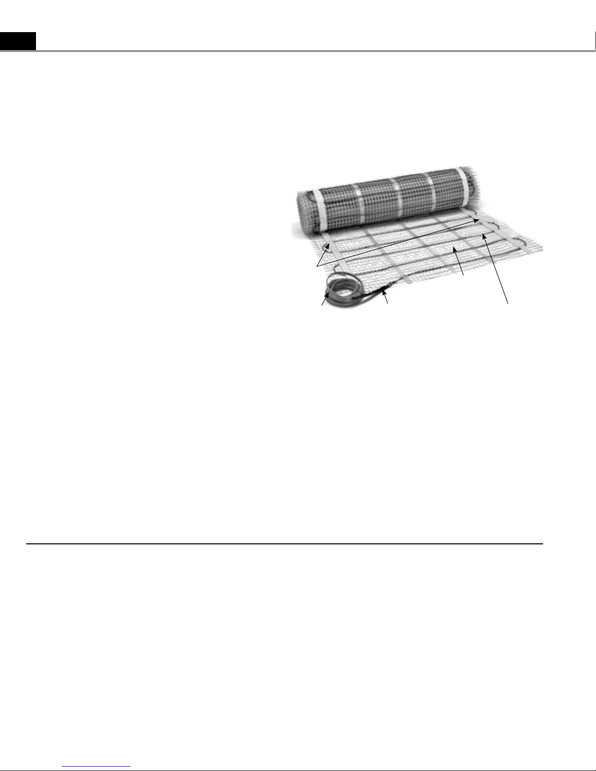
Doublesided Tape
Power lead
Factory Splice
Mat Mesh
Heating Wire
Skill Level
Installation must be performed by qualified persons, in accordance with local codes, ANSI/NFPA 70 (NEC Article 424) and CEC
Part 1 Section 62 where applicable.
Intermediate skills in electrical wiring required. The heating product may be secured in place by qualified installers, however,
consider hiring an electrician to rough in the power supply wiring. Please be aware local codes may require this
product and/or the SunStat control to be installed or connected by an electrician.
Expected floor temperature
Heating performance is never guaranteed. SunTouch TapeMat is designed to deliver 12 W/sq.ft. The floor temperature
attainable is dependent on how well the floor is insulated, the temperature of the floor before start up, and the overall thermal
drain of the floor mass. Insulation is required for best performance. Refer to Phase 5 for important design considerations.
Table of Contents
Phase 1 Designing the System . . . . . . . . . . . . . . . . . . . . . . . . . . . . . . . . . .pg 4
Phase 2 Preparations . . . . . . . . . . . . . . . . . . . . . . . . . . . . . . . . . . . . . . . . . . .pg 5
Phase 3 Electrical Rough-in . . . . . . . . . . . . . . . . . . . . . . . . . . . . . . . . . . . . .pg 8
Phase 4 TapeMat Installation . . . . . . . . . . . . . . . . . . . . . . . . . . . . . . . . . . . pg 9
Phase 5 Floor Coverings . . . . . . . . . . . . . . . . . . . . . . . . . . . . . . . . . . . . . . . .pg 13
Phase 6 Control Installation . . . . . . . . . . . . . . . . . . . . . . . . . . . . . . . . . . . . . pg 15
Appendices . . . . . . . . . . . . . . . . . . . . . . . . . . . . . . . . . . . . . . . . . . . . . . . . . . . . . . . . pg 16
Control Wiring . . . . . . . . . . . . . . . . . . . . . . . . . . . . . . . . . . . . . . . . . . . . . . . . . . . . . .pg 19
Connections . . . . . . . . . . . . . . . . . . . . . . . . . . . . . . . . . . . . . . . . . . . . . . . . . . . . . . . .pg 21
Troubleshooting . . . . . . . . . . . . . . . . . . . . . . . . . . . . . . . . . . . . . . . . . . . . . . . . . . . .pg 22
Warranty . . . . . . . . . . . . . . . . . . . . . . . . . . . . . . . . . . . . . . . . . . . . . . . . . . . . . . . . pg 23

Table 1
SunTouch TapeMat Installation Manual
CAUTIONS!
R eA d Be f O Re IN S T Al l I N g T Ap e M AT
3
As with any electrical product, care should be taken
to guard against the potential risk of fire, electric
shock, and injury to persons. The following cautions
must be observed:
NE VER install TapeMat under carpet, wood, vinyl, or
other non-masonry flooring without embedding it
in thin-set, thick-set, or self-leveling mortar.
NE VER install TapeMat in adhesives or glues
intended for vinyl tile or other laminate flooring. It
must be embedded in polymer-modified mortar.
NE VER cut the heating wire. Doing so will cause
dangerous overheating and will void the warranty.
The power lead may be cut shorter if necessary, but
never remove completely from the heating wire.
NE VER bang a trowel or other tool on the heating
wire. Be careful not to nick, cut, or pinch the wire
causing it to be damaged.
NE VER use nails, staples, or similar to fasten the
heating wire to the floor.
NE VER attempt to repair a damaged heating wire,
splice, or power lead using unauthorized parts. Use
only factory authorized repair parts and methods.
NE VER splice one mat heating wire to another mat
heating wire to make a longer mat. Multiple mat
power leads must be connected in parallel in a
junction box or to the thermostat.
NE VER install one mat on top of another or overlap
the heating wire on itself. This will cause
dangerous overheating.
NE VER forget to install the floor sensor included with
the thermostat.
NE VER extend the heating wire beyond the room or
area in which it originates.
NE VER allow a power lead or sensor wire to cross over
or under a heating cable. Damage could result.
AL WAYS completely embed the heating wire and
factory splices in the floor mortar.
AL WAYS maintain a minimum of 2" spacing between
heating wires.
AL WAYS pay close attention to voltage and amperage
requirements of the breaker, the thermostat, and
the TapeMat. For instance, do not supply 240 VAC
power to 120-VAC TapeMat as damage will result.
AL WAYS make sure all electrical work is done by
qualified persons in accordance with local building
and electrical codes, Section 62 of the Canadian
Electrical Code (CEC) Part I, and the National
Electrical Code (NEC), especially Article 424.
AL WAYS use copper only as supply conductors to the
thermostat. Do not use aluminum.
AL WAYS seek help if a problem arises. If ever in
doubt about the correct installation procedure to
follow, or if the product appears to be damaged,
the factory must be called before proceeding with
the installation.
NE VER install TapeMat in any walls, or over walls or
partitions that extend to the ceiling.
NE VER install mats under cabinets or other built-
ins having no floor clearance, or in small closets.
Excessive heat will build up in these confined
spaces, and the mat can be damaged by fasteners
(nails, screws, etc.) used to install built-ins.
NE VER remove the nameplate label from
the power leads. Make sure it is viewable for
inspection later.
Installation must be performed by qualified personnel,
in accordance with local codes and standards. A licensed
electrician is recommended. Read these important
warnings and all installation instructions prior to
installation. Failure to do so can result in fire, shock,
property damage, personal injury, and/or death.
4
SunTouch TapeMat Installation Manual
Phase 1: Designing the System
SunTouch TapeMat should be installed in all interior floor
areas intending to be warmed. It cannot be used for exterior
applications, snow melting, or in ceilings. In many applications
it can be used to heat the room but an accurate heat-loss
calculation must be made to determine if enough heat will be
provided to match the heat loss.
STEP 1.1
Make a sketch of the room and measure the overall room size.
Measurement should be made from wall-to-wall and include
size and location of cabinets, tub, toilets, etc. Determine
the total square footage of floor area to be warmed by
subtracting out the area associated with the built-ins. Keep in
mind the following:
• Heat will not radiate beyond about 1-1/2" on either
side of the heating wire, therefore consistent coverage
is important.
• Do install heating wire within about 1-1/2” to 2” from a
counter or vanity in the kick-space to ensure warmth in
this area.
• Do not install the heating wire underneath cabinets or
fixtures having no floor clearance or inside a wall. Excessive
heat will build up and cause damage.
• Do not run the heating wire into small closets or other
confined areas where excessive heat will build up.
• Do not install the heating wires closer than 6" from toilet
rings to avoid possible melting of wax rings.
• Do not directly cross expansion joints.
• Do not place the heating wire any closer than 4" from other
items such as forced air ducting or potable piping to avoid
overheating them.
• TapeMat must be laid in a manner to prevent surface
obstructions being placed directly over the mat location.
Failure to do so will result in capturing heat and may allow
potential damage from mounting brackets, bolts, or similar
penetrations associated with pedestals, support columns,
walls, or similar.
• Install the heating wires 4" to 6" away from the perimeter
walls of the room. It may be placed closer, but is
unnecessary since most people do not stand this close to
the wall. Make sure the heating wire will not be located
underneath finish trim.
• The heating wire and factory splices must be completely
embedded in the thin-set. Only the power lead may
exit the thin-set and enter the wall. Pull power leads
through UL Listed conduit to a UL Listed junction box or
the control box.
STEP 1.2
Multiply the heated area square footage calculated in Step 1.1
by 0.90 to allow 4" to 6" spacing around the edges of the floor
area. Use this resulting square footage to select the appropriate
mats from Table 2 on page 5.
Remember:
• Do not exceed 15 amps at 120 VAC (1800 watts) or
15 amps (3600 watts) at 240 VAC through a single SunStat or
SunStat Relay.
• Select either 120 VAC or 240 VAC depending on the power
available. DO NOT mix voltages on the same SunStat if more
than one mat is to be installed to cover an area.
• Load no more than 12 amps on a 15-amp circuit breaker, or
16 amps on a 20-amp circuit breaker.
• If the area requires more than 15 amps to be controlled by
one thermostat use SunStat Relays to take the additional amp
load.
• See the Wiring Diagrams in Appendix for further information.
If the exact size of product calculated is not found in the
selection Table 2 on page 5, it may be necessary to adjust the
warming area(s) or select the next smaller size. Remember, the
heating wire must never be cut shorter to fit, and must be
completely embedded in thin-set, thick-set, or self-leveling
concrete. Failure to do so may result in damage to the
product. Do not select a product larger than necessary.
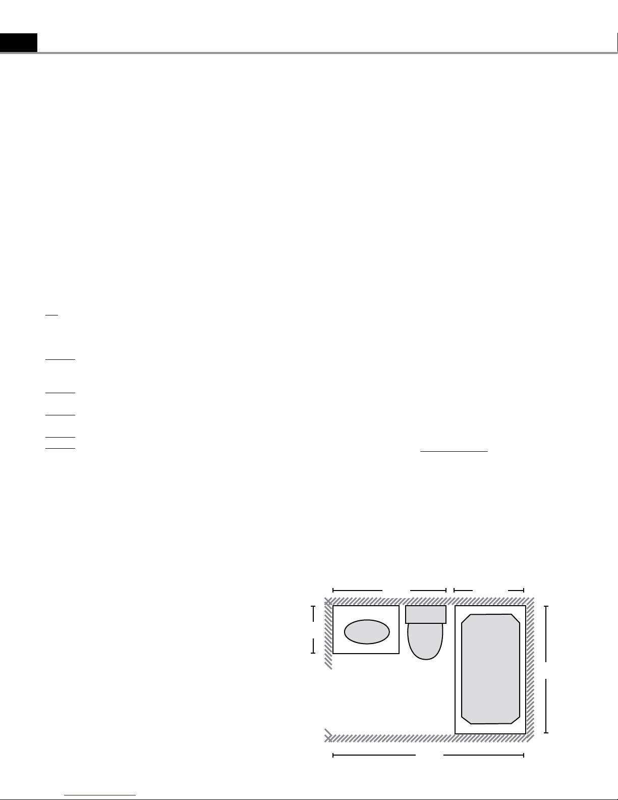
Small bath design
5 ft
2-1/2 ft
Gross Room Area: 8 x 5 = 40 sf
Built-in Areas
Sink and Toilet: 2 x 5 = 10 sf
Bath Tub: 2.5x 5 = 12.5 sf
Total Heated Area: 40 - (10 + 12.5) = 17.5 sf
TapeMat Coverage: 17.5 x 0.90 = 15.75 sf
Chosen TapeMat Size: 15 sf.
2 ft
Sink
Toilet
8 ft
Bath Tub
5 ft
SunTouch TapeMat Installation Manual
5
STEP 1.3
Make sure proper subfloor materials are selected in accordance
with the construction and floor covering requirements. Use of
an anti-fracture membrane, backerboard, or other materials are
recommended when installing tile or other stone floor covering.
STEP 1.4
Pay careful attention to the total amps when selecting
multiple mats to make sure the controls, circuit breaker
panel, and all wiring have the proper capacity. Design circuit
protection and wiring to handle 125% of total amp load.
Phase 2: Preparations
Before installing TapeMat, make sure to fully inspect the
products and carefully plan the site. The following steps may
not necessarily occur in the order shown, depending on
contractor and electrician scheduling and variations in site
preparation requirements.
Items Needed
Materials:
- SunStat thermostat control with floor sensor. The SunStat is
available from your SunTouch dealer. All other items can be
purchased locally. The SunStat is listed separately from the
TapeMat.
- 20-amp circuit breaker (single for 120-VAC and dual
for 240-VAC systems)
- UL Listed electrical box (extra deep) for the control;
single-gang (not a gangable type) for one or two mats or
4"-square deep box with a single-gang "mud ring" cover
- 4" junction box with a cover (if needed)
- Flexible or rigid UL Listed conduit (for new construction)
- 12-gauge or 14-gauge electrical wiring cable
(consult local code)
- Wire nuts if using an additional junction box
- Nail plate
Tools:
- Di gital multi-meter for ohms testing;
must read up to 20,000 ohms to measure sensor
- Drill with 1/2" & 3/4" bits
- Hammer and chisel
- Wire strippers
- Phillips screwdriver
- Fish tape
- Hole saw
- Floor covering installation tools
Note: Installer must be familiar with electrical wiring
techniques (licensed electrician recommended). If
applicable for the installation, installer must also be
familiar with floor covering techniques.
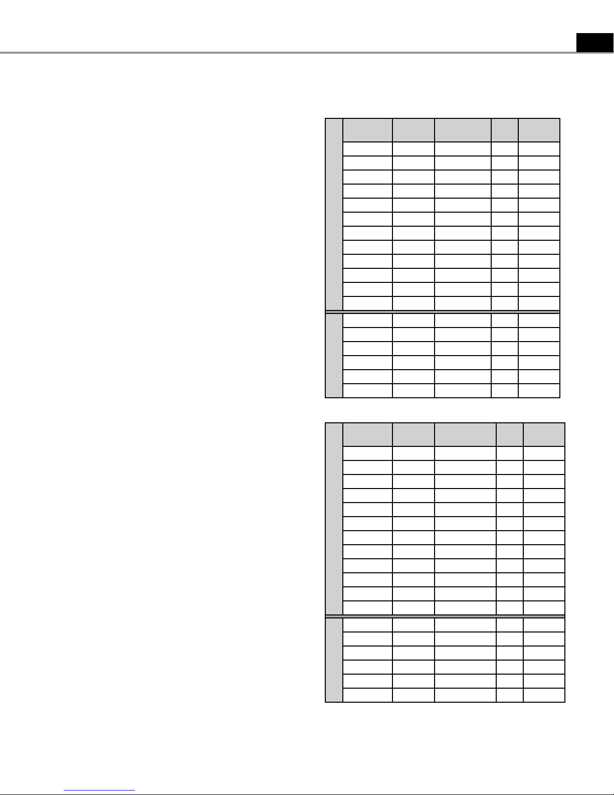
Table 2 (TapeMat sizes)
120 VAC
Mat Square
Footage
10 2' x 5' 12000524 1.0 102-125
15 2' x 7'-6" 12000724 1.5 71-87
20 2' x 10' 12001024 2.0 49-60
25 2' x 12'-6" 12001224 2.5 39-48
30 2' x 15' 12001524 3.0 30-37
35 2' x 17'-6" 12001724 3.5 25-31
2 ft Wide
40 2' x 20' 12002024 4.0 22-27
45 2' x 22'-6" 12002224 4.5 19-23
50 2' x 25' 12002524 5.0 17-21
60 2' x 30' 12003024 6.0 14-17
70 2' x 35' 12003524 7.0 12-14
80 2' x 40' 12004024 8.0 11-13
15 3' x 5' 12000536 1.5 71-87
20 3' x 6'-8" 12000636 2.0 49-59
25 3' x 8'-4" 12000836 2.5 39-48
30 3' x 10' 12001036 3.0 30-36
3 ft Wide
45 3' x 15' 12001536 4.5 19-23
60 3' x 20' 12002036 6.0 14-17
240 VAC
Mat Square
Footage
20 2' x 10' 24001024 1.0 206-252
30 2' x 15' 24001524 1.5 148-180
40 2' x 20' 24002024 2.0 98-120
50 2' x 25' 24002524 2.5 79-97
60 2' x 30' 24003024 3.0 60-64
70 2' x 35' 24003524 3.5 50-62
2 ft Wide
80 2' x 40' 24004024 4.0 43-53
90 2' x 45' 24004524 4.5 38-47
100 2' x 50' 24005024 5.0 34-42
120 2' x 60' 24006024 6.0 28-35
140 2' x 70' 24007024 7.0 24-29
160 2' x 80' 24008024 8.0 22-27
30 3' x 10' 24001036 1.5 144-176
40 3' x 13'-4" 24001336 2.0 97-118
50 3' x 16'-8" 24001636 2.5 78-95
60 3' x 20' 24002036 3.0 60-74
3 ft Wide
90 3' x 30' 24003036 4.5 38-47
120 3' x 40' 24004036 6.0 28-35
Mat Size
(W x L)
Mat Size
(W x L) Model Number
Model
Number
Amp
Draw Ohms
Amp
Draw Ohms
It is important to select the proper sized TapeMat for the given
area. TapeMat can not be cut shorter in order to fit a given area.
Doing so will damage the heating wire and will prevent the system
from working.
6
SunTouch TapeMat Installation Manual
Tips
Co ntrols: The SunStat controls will provide direct
floor-warming control or can be set to sense air
temperature with a floor temperature limit. Other controls
may not give the same desired level of control or overall
comfort and are not recommended.
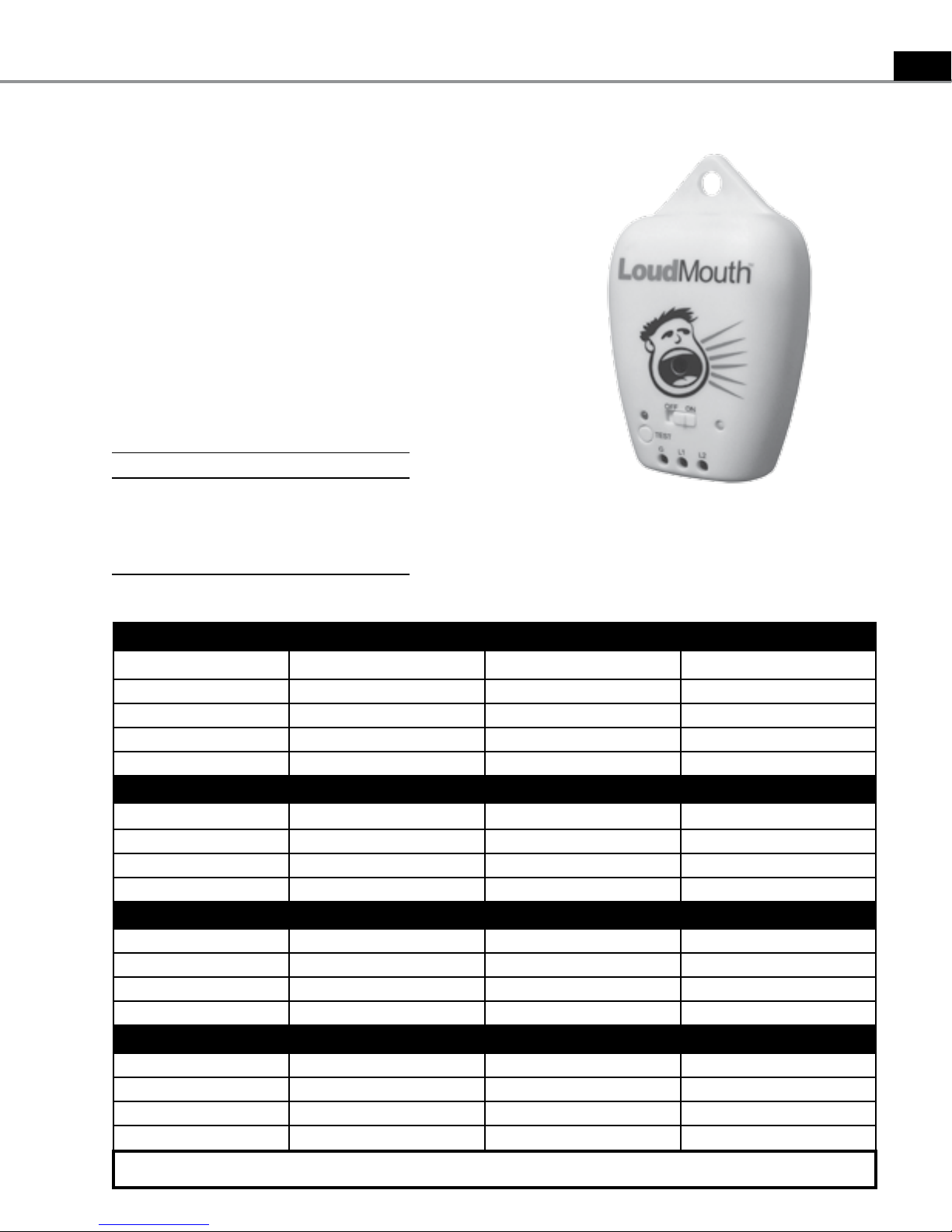
Lo udMouth™: The LoudMouth is a continuity monitor with an
integrated alarm. An alarm will sound if damage occurs to
the heating wire during installation. The LoudMouth stays
connected to the power leads throughout the TapeMat
installation. A small screwdriver for connecting the leads is
included with the LoudMouth monitor.
INSPECT CABLE, CONTROL, and SENSOR
CAUTION: Make sure power is not applied to the
product until it is fully installed and ready for final
testing. All work must be done with power turned
off to the circuit being worked on.
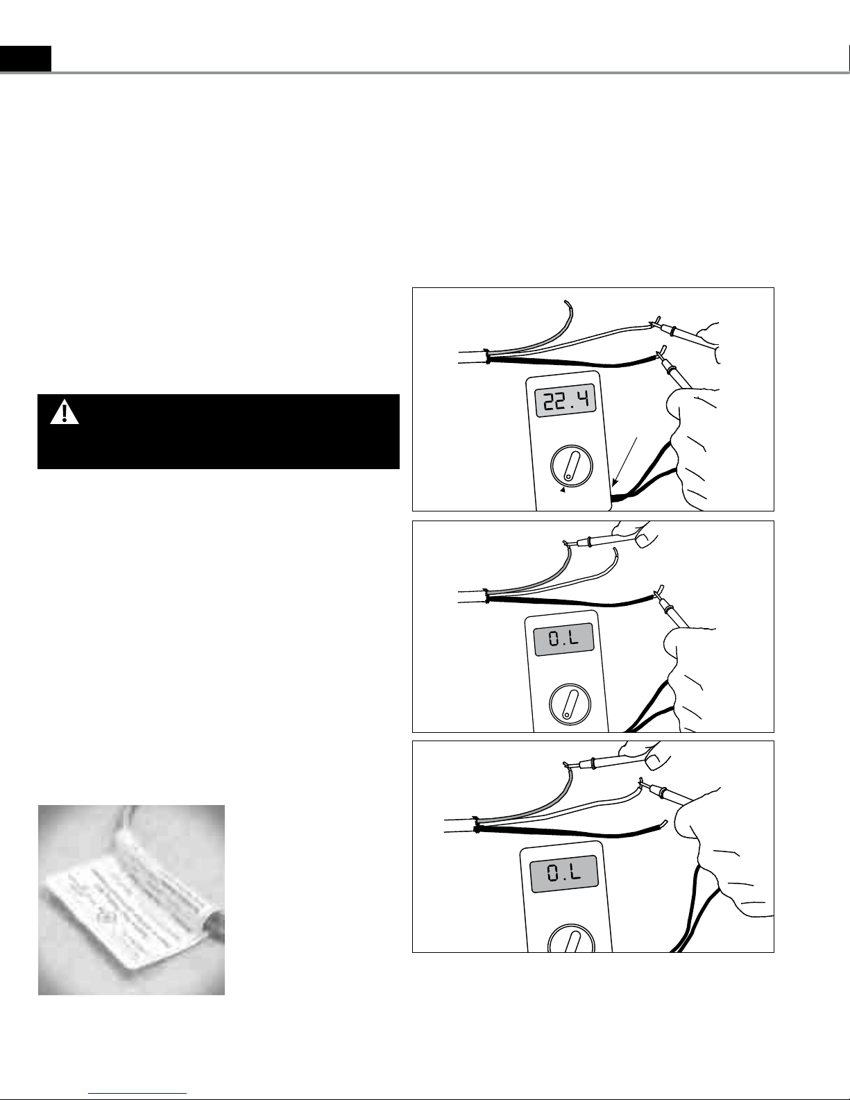
STEP 2.3
Use a digital multi-meter set to the 200Ω or 2000Ω (2kΩ)
range to measure the resistance between the conductors
of the mat power leads. Record these resistances in Table 4
under “Out of the box before installation”.
The resistance should measure within the resistance range
on the nameplate label. If it is a little low, it may be due
to low air temperatures or meter calibration. Consult the
factory if in doubt.
Ground Lead
200 ohm setting
White or Blue Lead
Black Lead
Black wire to COM
Red wire to Ω
STEP 2.1
Remove the TapeMat, control, and sensor from their
packages. Inspect them for any visible damage
and verify everything is the correct size and type
according to the plan and the order. Do not attempt to
install a damaged product.
STEP 2.2
Record the product information in Table 4. Give this
information to the homeowner to keep in a safe place.
The TapeMat model number, serial number, voltage, and
resistance range are shown on a nameplate label attached
to the power leads, as well as the marking "(x)-FOR INDOOR
FLOOR HEATING APPLICATIONS".
Do not remove this nameplate label. The electrical
inspector will need to see this.
Record the information from the
nameplate label into the Mat
and Sensor Resistance Log.
Leave the nameplate label
attached to the power leads for
later inspection.
Ground Lead
Ground Lead
White or Blue Lead
Black Lead
White or Blue Lead
Black Lead
Press the test lead tips to the Black and White (or Blue for 240 VAC) power lead wires.
This reading should correspond to the factory resistance range on the nameplate label
attached to the Power lead.
Readings between the White (or Blue for 240 VAC) and Ground or the Black and Ground
power lead wires should measure “open”, or “O.L”, or the same as displayed when the test
leads are not touching anything.
Measure the resistance between either of the white or
black leads and ground lead. This measurement should be
“open”, usually indicated by an “OL” or a “I”. This is the same as
displayed when the test leads are not touching anything.
If there is any change in the reading, record this information
and contact the factory before continuing. This could
indicate damage, test lead problems, or a number of other
issues. Try “pinning” the test leads to the cable lead wires
against a hard non-metal surface if the readings continue to
fluctuate.
Change the meter to the 20,000 ohms (20 kΩ) range.
Measure between the lead wires of the floor sensor. This
resistance varies according to the temperature sensed.
Table 3 provides approximate resistance-to-temperature
values for reference.
Table 3 (floor sensor resistance values)
Temperature Typical Values
55°F (13°C) 17,000 ohms
65°F (18°C) 13,000 ohms
75°F (24°C) 10,000 ohms
85°F (29°C) 8,000 ohms
SunTouch TapeMat Installation Manual
The LoudMouth monitor (sold separately) will constantly monitor
the heating wire during the entire installation process. If the wire is cut or damaged
during installation, the LoudMouth will sound an audible alarm.
7
Table 4 - TapeMat Resistance Log
Mat 1 Mat 2 Mat 3
Mat serial number
Mat model number
Mat voltage
Mat resistance range
Sensor
OUT OF THE BOX BEFORE INSTALLATION
Mat white to black
Mat white to ground
Mat black to ground
Sensor
AFTER MAT IS SECURED IN PLACE
Mat white to black
Mat white to ground
Mat black to ground
Sensor
AFTER SLAB IS POURED
Mat white to black
Mat white to ground
Mat black to ground
Sensor
Retain this log to retain the warranty! Do not discard!
8
SunTouch TapeMat Installation Manual
Phase 3: Electrical Rough-in
STEP 3.1:
Circuit Breaker (Overcurrent Protection)
SunTouch TapeMat(s) must be protected against overload
by a circuit breaker. GFCI type (ground fault circuit interrupter)
or AFCI type (arc-fault circuit interrupter) breakers may be
used if desired, but are not necessary.
The rating of the breaker (see Table 5) is determined by
the amp draw of the heating mats (see Table 2 or the
Nameplate Label). If multiple mats are to be controlled by one
SunStat, total their amp draws. If this total exceeds 15 amps,
an additional breaker will be required. The total amps on each
breaker can not exceed 15 amps. Do not use breakers rated
over 20 amps.
Table 5 - Circuit Breakers and Supply Wire
Mat(s) Supply Wire Breaker
VAC total amps (AWG)* qty type** rating
120 up to 12 amps 14 1 SP 15 or 20 A
120 up to 15 amps 12 1 SP 20 A
240 up to 12 amps 14 1 DP 15 or 20 A
240 up to 15 amps 12 1 DP 20 A
* Recommended only. Follow local codes for wire gauge size.
** SP= single-pole, DP=double-pole
STEP 3.2:
Install Electrical Boxes
SunStat Thermostat:
Install an extra-deep electrical box for the SunStat
thermostat. Follow the instructions included with the
SunStat for complete information on location and wiring.
SunStat Relay:
Install an extra-deep electrical box for any SunStat Relay(s).
The SunStat Relay is used when more than 15 amps must
be controlled by one SunStat thermostat. Follow the
instructions included with the SunStat Relay for complete
information on location and wiring.
Junction Boxes:
If a mat is to be located so its Power lead is not long enough
to reach the SunStat or SunStat Relay directly, a junction
box must be installed. Do not attempt to make a
connection to other wiring without a junction box. Use a
standard junction box with a cover, mounting it below the
subfloor, in the attic, in the wall, or in another location
easily accessible after all coverings are complete.
For construction with an existing wall or where the wall is
covered, cut the necessary openings to mount the electrical
boxes listed above. Wait to install the boxes until all wiring is
fed into these locations to make it easier to pull the wire.
Note: The SunStat sensor wire can be extended up to a
maximum of 50’. Follow the installation instructions
that are included with the SunStat for details.
It may be possible to tap into an existing breaker as long as
there is adequate capacity for the mat(s) and any additional
appliance, such as a hair dryer or vacuum cleaner. Avoid
circuits which have lighting, motors, exhaust fans, or hot tub
pumps due to possible interference.
!
CAUTION
Do not perform any electrical work unless qualified to do
so. Work should be done with great care and with power
turned off to the circuit being worked on. Follow all local
building and electrical codes.
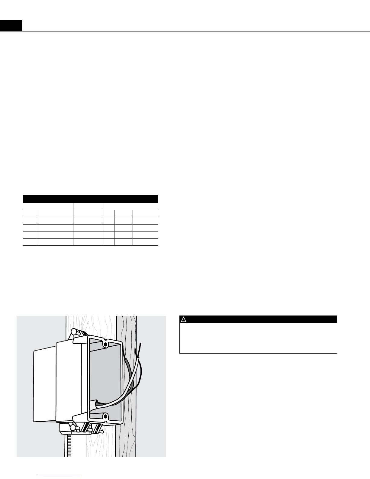
Install an extra-deep single-gang box if
connecting one or two cables to the control.
Use a 4"-square deep box with a singlegang mud ring cover if connecting three
cables, because the extra room is needed
for the wire, wire nuts, and control.
 Loading...