

SunTouch 500670, SunStat Pro Owner's Manual
SunStat Pro
Programmable Thermostat
Model 500670
Owner’s Manual
Your new SunStat Pro thermostat is designed to control the voltage to
either a 120VAC or 240VAC resistive oor warming system.
Please follow this manual for complete installation and operation instructions.
If you have any questions or comments, tr y calling Technical Support at
1-888-432-8932.
CAUTION: Make sure you are qualied and are familiar with house wiring.
This is a line voltage device that could cause serious injury or damage if
improperly installed.
1. Preparation
1. Unpack your thermostat and make sure every thing is in good condition:
•Thermostat
•Floor sensor
•Small screwdriver
•Mounting screws
•Wire nuts for wiring connections
If any parts are missing or damaged, contact the store where you purchased
this thermostat. Do not install a damaged par t.
2. Gather the following tools and supplies:
•Phillips screwdriver, hole saw
•Wire strippers, “sh tape”, other electrical tools
•Electrical box for thermostat:
a. If you are connecting to power leads from only 1 or 2 oor warming
systems, you may use a single-gang, 31⁄2 inch deep box.
b. If you are connecting to power leads from 3 oor warming systems,
use a 4x4x21⁄8 inch or deeper box (not a 2-gang box) when your wall studs
are still exposed. Install a single-gang “mud-ring” cover on the box before
installing drywall materials.
c. For more than 3 oor warming systems or other layouts, you may need
to install a junction box to connect the power leads together. Then use
house wire to connect between the junction box and the thermostat
electrical box. See the installation instructions for your oor warming
system for more information.
ALWAY S: Wire all circuits as Class 1, Electric Light and Power Circuits.
ALWAY S: Wire all circuits with insulation rated 600V minimum.
ALWAY S: Mount this control only to a grounded metallic box or a
nonmetallic box.
ALWAY S: Use power supply wires suitable for at least 90°C.
CAUTION: High voltage – disconnect power supply before servicing.
CAUTION: The GFCI in this control does not protect against shock if both
2. Installation
Remove the Thermostat Face
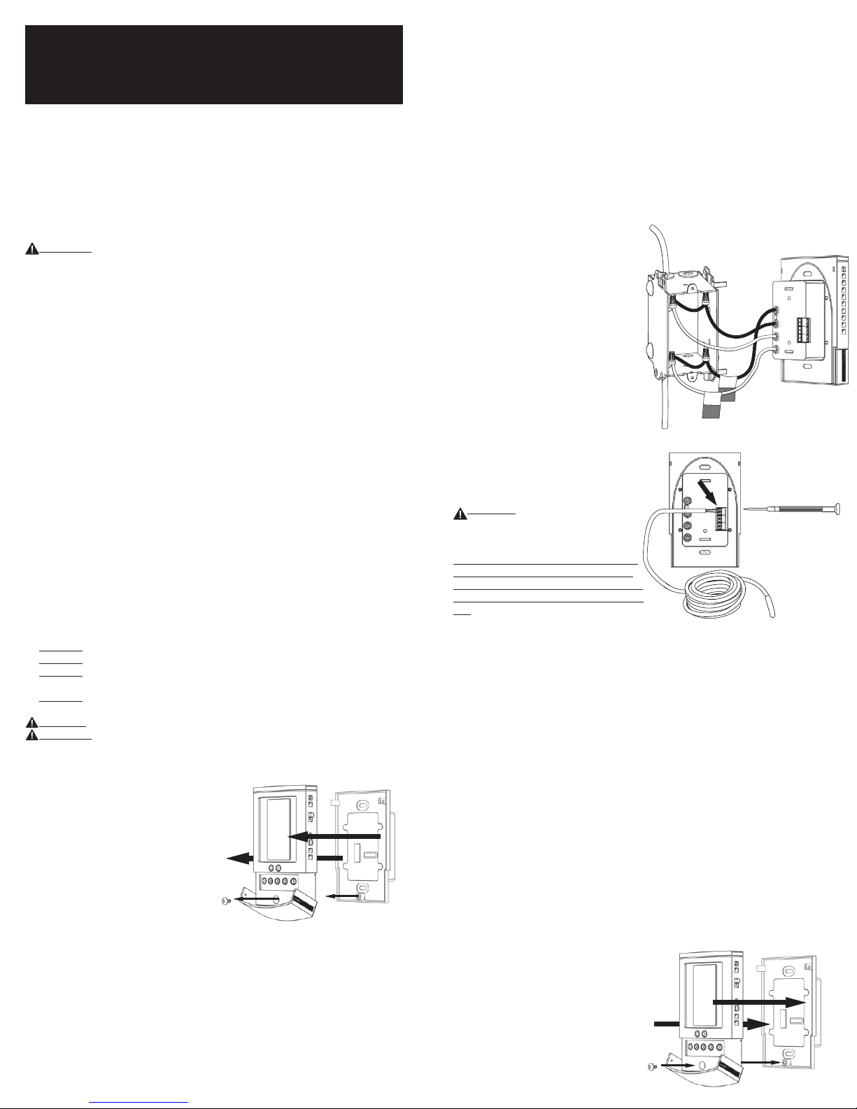
1. Remove the thermostat Front Module
from the Power Module by opening the door
and loosening the screw.
2. 2. Pull outward near the bottom on the
Front Module and lift off. Be careful not
to bend or damage the 14-pin electrical
connector on the back of the Front Module.
Prepare the Wiring
1. Find a location for your thermostat. It is suitable for indoor use only, on
insulated or uninsulated walls. Locate it about 41⁄2 feet to 5 feet above the
oor on an inside wall. Make sure it is well ventilated and not located in a
conned space such as a small closet or cabinet. Avoid placing it near other
heat sources such as hot-water piping, heat duct, wall-mount lighting, and
direct sunlight to help prevent adversely affecting the thermostat.
2. Turn off the power to the oor warming system at the main circuit panel
before doing any electrical work.
3. A qualied electrician should run a dedicated circuit from the main circuit
panel to the thermostat location.
4. If a dedicated circuit is not possible, you may tap from another circuit in the
room. Make sure there is enough load capacity (amps) to handle the addition
of your oor warming system, and that it is NOT wired in series with any other
bare conductors are touched at the same time.
front
module
power
module
device, including other GFCIs.
5. The circuit breaker in the main circuit panel should be 15 amps maximum
for a oor warming system totaling 12 amps or less. For larger systems up
to 15 amps, use a 20 amp maximum circuit breaker. Never exceed 15 amps
on this thermostat. You may consider using an arc-fault (AFCI) type circuit
breaker for additional protection.
6. Mount the electrical box.
7. Pull the power supply wiring into this box, leaving about 6 inches of wire.
8. Pull the oor sensor wire and the power lead wires from your oor warming
system up the wall, into this box. Refer to your oor warming system
installation instructions for placement of the oor sensor tip into the oor area.
Note: The sensor wires should not be run in the same conduit as line voltage
wires to avoid possible interference. If the sensor lead wires are not long
enough, they may be extended an additional 15 feet (4.5 m) using minimum
20-gauge 2-conductor wire or up to 50 feet (15 m) using shielded wire.
1-4
5
from
power
supply
to
oor
warming
system
sensor
Connect Wires
1. Match and connect the two wires
marked “LINE1” and “LINE2” to the
power supply wires using the wire nuts
provided.
2. Gently tug on the wires to make sure
they are secure, otherwise a wire could
loosen and cause failure.
3. Overwrap the wire nuts with electrical
tape to better secure them to the wires.
4. Match and connect the two wires
marked “LOAD1” and “LOAD2” to the
oor warming system lead wires and
secure these wires the same way.
5. Connect the house ground wire to the
green or bare lead wire(s) of your oor
warming system.
6. Insert the ends of the oor sensor
wire into the “SENSOR” terminals (1 and
2) and tighten the screws. There is no
polarity, so it does not matter which wire
end goes into which terminal.
CAUTION: Before continuing, make
sure your power supply voltage matches
the voltage rating of your oor warming
system.
Connecting 240V to a 120V oor warming system will cause overheating and
damage to the system and may damage
the control, other wiring, oor coverings,
etc.
Remote Control
1. If you want to connect your thermostat to a remote control device, such as
a home automation system, rst make sure that the remote device has a “dry
contact, normally open” output (an un-energized switch, such as the contacts on
a relay). Many home automation systems come with such an output that opens
or closes at specied times.
2. Pull 2-conductor wire, size 18- to 24-guage, through the wall from the remote
device, into this electrical box.
3. Connect the wire ends into the “SETBACK” terminals (5 and 6) and tighten
the screws (no polarity).
SunStat Relays
1. If you want to use your thermostat to drive a SunStat Relay(s) (ask your dealer
about this convenient way to control larger systems with one thermostat), rst
read and follow the instructions for the SunStat Relay thoroughly.
2. Pull 2-conductor wire, size 18- to 24-gauge, through the wall from the SunStat
Relay, into this electrical box. This wire may be up to 100 feet (30 m) in length
from the thermostat to the last SunStat Relay installed.
3. Connect the wire ends into the “RELOUT” terminals (3 and 4) and tighten the
screws(Observe polarity of the wires when connecting to the SunStat Relay).
Mount the Thermostat
1. Carefully fold and press the wires back into the electrical box. Do not use
the thermostat to push them in, as this may cause connections to loosen and
possible failure.
2. Secure the thermostat Power Module into the box with the mounting screws
provided.
3. Carefully align the Front Module with the
Power Module to avoid bending any of the
pins on the Front Module while snapping
them together.
4. Tighten the screw.
5. Switch on the power at the main circuit
panel.
NOTE to contractors: After installing the
thermostat, be sure to:
a. Do a Quick Setup (section 3),
b. Temporarily override the setpoint
MO
M
A
SET TEMP
LIMIT
FLOOR
°F
MO
SET TEMP
CYCLE
M
A
°F
HOLD
FLOOR
MO
CYCLE
M
A
°F
FLOOR
MO
M
A
SET TEMP
LIMIT
FLOOR
°F
MO
M
A
HEATING
MO
SET TEMP
CYCLE
M
A
°F
HOLD
USAGE
MO
CYCLE
M
A
°F
SET BACK
FLOOR
FLOOR
MO
CYCLE
M
A
°F
FLOOR
MO
CYCLE
M
A
°F
FLOOR
temperature to make sure it is
heating for a few minutes (section 5),
c. Test the GFCI (section 5).
3. Quick Setup
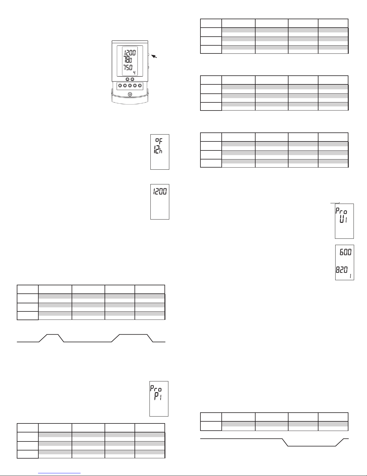
On/Off Switch
Your thermostat should be turned off when it
is rst installed. The display will show OFF and
the time and day.
1. Slide the on/off switch to the upper position,
turning the thermostat on. The display will
show the time and day, temperatures, and other
information.
2. To turn the thermostat off anytime, slide the
on/off switch to the lower position. No heating
will occur and all programming is retained.
Change Format Between °F / 12-hour and °C / 24-hour
Your thermostat is factor y set to operate in either °F / 12 hour format or °C /
24 hour (military time) format. If needed, you may change this at any time as
follows:
1. Press the OPTIONS button and hold for 1 second. An °F and
12h will show on the display.
2. Press the down or up button to toggle to °C and 24h.
3. Press the HOLD/RETURN button to return to the normal
operating mode.
Set the Current Time and Day
1. Press the DAY/TIME button and hold for 1 second. The hour should be
blinking.
2. Press the down or up button to adjust the hour, and AM/PM if
using the 12-hour clock format.
3. Press the DAY/TIME button briey. The minutes should be
blinking.
4. Press the down or up button to adjust the minutes.
5. Press the DAY/TIME button briey. The day should be blinking.
6. Press the down or up button to adjust the day.
7. Press the HOLD/RETURN button or wait 15 seconds and the thermostat will
return to the normal operating mode, saving your settings.
Use the Factory Programmed “User” Schedule
If you want to begin using your thermostat now without making any changes to
the factor y set programming schedule, you may skip to section “5 Operation” .
It will operate in the “User” Schedule (U1), pre-programmed as follows, and
can be customized later to your needs (see section “4 Additional Setups”):
U1 (User changeable)
Cycle 1 2 3 4
Mon-Fri
Saturday
Sunday
Note: Air Sensing mode default temperatures are 70F and 62F.
6:00 am 8:00 am 5:00 pm 10:00 pm
82 F 74 F 82 F 74 F
7:00 am 9:00 am 5:00 pm 11:00 pm
82 F 74 F 82 F 74 F
7:00 am 9:00 am 5:00 pm 11:00 pm
82 F 74 F 82 F 74 F
82 F 82 F
74 F 74 F
MO
A
M
SET TEMP
CYCLE
FLOOR
on/off
°F
4. Additional Setups
Lifestyle Program Schedules (Presets)
There are convenient schedules already set up to meet typical lifestyles. If you
see a schedule P1 through P4 you like, select one as follows:
1. Press the PROGRAM button and hold for 1 second. Pro and
U1, P1, P2, P3, or P4 will show on the display.
2. Press the down or up button briey to select P1, P2, P3, or P4.
These schedules are not able to be modied, and are as follows:
P1 (Early Riser)
Cycle 1 2 3 4
Mon-Fri
Saturday
Sunday
Note: Air Sensing mode default temperatures are 70F and 62F.
5:00 am 7:00 am 5:00 pm 10:00 pm
82 F 74 F 82 F 74 F
5:00 am 9:00 am 5:00 pm 10:00 pm
82 F 74 F 82 F 74 F
5:00 am 9:00 am 5:00 pm 10:00 pm
82 F 74 F 82 F 74 F
P2 (Longer Day)
Cycle 1 2 3 4
Mon-Fri
Saturday
Sunday
Note: Air Sensing mode default temperatures are 70F and 62F.
P3 (At home during the day)
5:00 am 8:00 am 6:00 pm 11:00 pm
82 F 74 F 82 F 74 F
6:00 am 9:00 am 5:00 pm 11:00 pm
82 F 74 F 82 F 74 F
6:00 am 9:00 am 5:00 pm 11:00 pm
82 F 74 F 82 F 74 F
Cycle 1 2 3 4
Mon-Fri
Saturday
Sunday
Note: Air Sensing mode default temperatures are 70F, 67F, and 62F.
P4 (Take the chill off)
6:00 am 8:00 am 6:00 pm 10:00 pm
82 F 79 F 82 F 75 F
6:00 am 9:00 am 6:00 pm 10:00 pm
82 F 79 F 82 F 75 F
6:00 am 9:00 am 6:00 pm 10:00 pm
82 F 79 F 82 F 75 F
Cycle 1 2 3 4
Mon-Fri
Saturday
Sunday
Note: Air Sensing mode default temperatures are 65F and 60F.
MO
A
M
3. Press the HOLD/RETURN button or wait 15 seconds and the thermostat will
return to the normal operating mode, saving your selection. The thermostat
will now display a P1, P2, P3, or P4 at the bottom right.
6:00 am 9:00 am 6:00 pm 10:00 pm
75 F 70 F 75 F 70 F
7:00 am 10:00 am 6:00 pm 10:00 pm
75 F 70 F 75 F 70 F
7:00 am 10:00 am 6:00 pm 10:00 pm
75 F 70 F 75 F 70 F
Customized Program Schedule (User)
To customize the program shedule to meet your needs, follow
these steps:
1. Press the PROGRAM button and hold for 1 second. Pro and
U1, P1, P2, P3, or P4 will show on the display.
2. Press the down or up button to select U1.
3. Press the PROGRAM button briey. CYCLE 1 and MO through
FR will show on the display. The hour should be blinking.
4. Press the down or up button to adjust the hour.
5. Press the PROGRAM button briey. The minutes should be
blinking.
6. Press the down or up button to adjust the minutes.
7. Press the PROGRAM button briey. The setpoint temperature
should be blinking.
8. Press the down or up button to adjust the setpoint temperature.
Note: A good rule of thumb is to adjust this about 5 to 8°F (3 to 5 °C)
lower during cycles when you are away to help reduce energ y use. If you
set the “away” cycles too low, it will take much longer to raise the
temperature again and may result in unsatisfying per formance.
Note: Some wood and laminate oor manufacturer s recommend a
maximum of 82 to 84°F (27° to 28°C). Check with manufacturer.
9. Press the PROGRAM button briey to move to the next cycle number.
10. Repeat Steps 3 through 7 to adjust the remaining cycle times and setpoint
temperatures MO through FR, and for the other days of the week.
Note: Cycle 4 must never be set to a point past 11:59 pm. If cycle 4 is set to
midnight or later, the thermostat may not cycle properly.
11. When you nish, or at any time during these adjustments, press the
HOLD/RETURN button or wait 30 seconds and the thermostat will return to the
normal operating mode. Your adjustments will be saved.
Note: The display in normal operating mode will not show a “U1” indicating
“User” schedule. Also, all schedule adjustments are saved in memory and
will not be lost during a brief power failure.
Note: If you only want to use two cycles during a day, clear the other cycles
by reducing their temperature below 40°F (4.5°C) to show (---). Cycle 4 must
always be used for the system to cycle properly.To use these cycles again,
adjust their time and temperature.
Example
Cycle 1 2 3 4
Mon-Fri
--:-- --:-- 7:30 am 6:00 pm
-- F -- F
72 F 80 F
80 F 80 F
72 F
MO
TUWE TH
FR
A
M
°F
CYCLE
 Loading...