

suntouch SunStat Command 108001, SunStat Command 108002, SunStat Command 108003, SunStat Command 108004, SunStat Command 108005 Installation And Operation Manual
Box Contents
• SunStat Command Thermostat
• Floor sensor
• Screwdriver
• Installation manual
• 2 machine screws
• 5 wire nuts
74
°F
74
°F
Floor
Smart Start
Setpoint
6:27Fri, May 01
AM
HEATING
TESTRESET
GFCI / TEST MONTHLY
Please be aware local code s may require this control to
be installed or conne cted by an electrician.
Read this manual BEFORE usin g this
equipment.
Failure to read and follow all safety a nd
use information can re sult in death, serious
personal injury, property damage, or damage
to the equipment.
Keep this manual for future re ference.
Important Safety Information
This pictorial aler ts you to electricity,
electrocution, and shock hazards.
This symbol identifies hazards which,
if not avoided, could result in d eath or
serious injury.
This symbol identifies hazards which,
if not avoided, could result in mino r or
moderate injury.
This symbol identifies practices, actions, or
failure to act, which could re sult in property
damage or damage to the equi pment.
This is a safety-aler t symbol. The safety-a lert
symbol is shown alone or use d with a signal word
(DANGER, WARNING, or CAUTION), a pictor ial
and/or a safety messag e to identify hazards.
When you see this symbol alon e or with a signal word on
your equipment or in this ma nual, be alert to the potent ial
for death or serious pe rsonal injury.
This device complies with Pa rt 15 of the FCC Rules and with
Industry Canada license-exempt RSS standard(s). Operation
is subject to the following two co nditions: (1) this device may
not cause harmful inter ference, and (2) this device must
accept any interference received, including interference
that may cause undesired operation.
Installation
Location
Items Needed
Installation must be performed by qualified persons, in
accordance with loca l codes, ANSI/NFPA 70 (NEC Arti cle
424) and CEC Part 1 Section 62 where a pplicable. Prior
to installation, please co nsult the local codes in o rder to
understand what is a cceptable. To the extent this information
is not consistent with loc al codes, the local co des should
be followed. Regardless, e lectrical wiring is required from a
circuit breaker or other el ectrical circuit to the control. It is
recommended that an electrician perform these installation
steps. Please be aware local c odes may require this product
to be installed by an elect rician.
NEVER forget to install the floor sensor included with the thermostat.
NEVER put the system into full operat ion until the tile or flooring
installer verifies a ll cement materials are fully cured (t ypically
two to four weeks after insta llation).
ALWAYS use copper sup ply conductors to the thermostat. Do
not use aluminum.
ALWAYS wire all circuits as C lass 1, electric light & power circuits.
ALWAYS wire all circuits wi th insulation rated 600V minimum.
ALWAYS mount this control to a g rounded electrical box.
ALWAY S use power supply wires suitab le for at least (194°F) 90°C.
ALWAYS seek help if a prob lem arises. If ever in doubt about
the correct install ation procedure to follow, or if the product
appears to be damage d, the factory must be called before
proceeding with the installation.
• Electric al box (must be UL Listed and proper size)
• Wire nuts (must be U L Listed and proper size)
• Flexible or rigi d conduit (if required, must be UL Listed and
proper si ze)
• 12-guage or 14-guage electr ical wiring cable (UL Listed)
• Nail plate
• Hot glue gun and ho t glue
• Thermostat is designed for indoor dry location only.
•
Do not install where there i s a draft, direct sun, hot-water piping,
ducting or other cause for inaccurate temperature readings.
•
Do not install where there i s electrical inter ference from
equipment, applianc es, or other sources.
•
Install away from all water source s such as sinks and at least
4' (1.2 m) away from showers and bathtubs.
• Consider e asy access for wiring, viewing, and adjusting.
•
Install at a suitable hei ght, normally about 4-1/2' to 5' (1.4 m
to 1.5 m) from the floor.
The following cautions must be observed:
Specifications:
Power supply 120/240 V (ac), 60 Hz, 3 watts
Maximum load 15 amps, resistive
Maximum power 1800 watts at 120 VAC
3600 watts at 24 0 VAC
GFCI
Class A (5 milliamp trip)
Approvals UL 943, UL 873, U L 991, FCC
Meets Class B: ICES -003 & FCC Part 15B
Ambient conditions 3 2 to 86°F (0 to 30°C), <90% RH non- condensing
Floor Sensor Thermistor, 10k NTC type, 300 V jacketed ca ble,
15' long
To prevent the risk of personal injur y and/or
death, make sure power is not applie d to the
product until it is fully ins talled and ready for
final testing. All work must b e done with power
turned off to the circuit b eing worked on.
To reduce the risk of electric shoc k, do not connect to a
circuit operating at mo re than 150 V to ground.
Power Supply
Pull power supply wiring to the contr ol location.
• Leave about 6 to 8" (15 to 20 cm) of wire for connection s.
•
This wiring should be size 12 or 14 AWG, in compliance with
local code requirements.
•
A qualified perso n should run a dedicated circuit fr om the main
circuit breaker panel to the c ontrol location. If a dedic ated
circuit is not possible, i t is acceptable to tap into an existing
circuit. However, there must be enough cap acity to handle
the load (amps) of the floor heating system being installed,
and any appliance likely to be us ed on the circuit such as a
hair dryer or vacuum cleaner.
• Avoid circuits that have ball asted lighting, motors, exhaust
fans, or hot tub pumps to reduc e the likelihood of interference.
•
The circuit breaker shoul d be rated 20 amps for total circuit
loads up to 15 amps. A 15-amp circuit breaker may be us ed
for total circuit loads up to 12 amps.
•
A GFCI (ground-fault circuit in terrupter) or AFCI (arc-fault
circuit interrupter) t ype circuit breaker may be used, but is
not necessary.
Thermostat Wiring
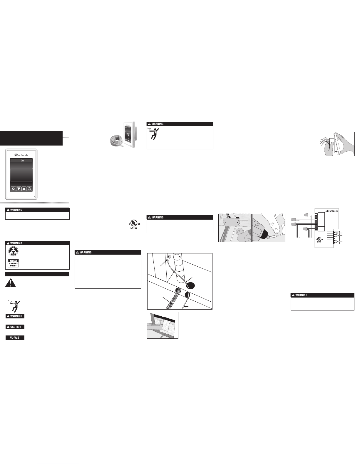
Before connecting the wires to the back of the thermostat,
detach the display front fro m the base.
Bottom Plate Work
•
Drill or chisel holes a t the bottom plate as indicate d. One
hole is for routing the power lead conduit and the other is
for the thermostat sensor. These holes should be directly
below the electrical box(es).
Make sure 120 VAC is supplied to 120 VAC cables and 240
VAC is supplied to 240 VAC cables. Otherwise, dang erous
overheating and a fire haz ard could result. Do not exceed
15-amps on this control.
SunStat Sensor Inst allation
•
The SunStat sensor c an be installed with or without elec trical
conduit depending on code requirements. Conduit is
recommended for add ed protection against nails and scr ews.
• Do not place the s ensor in the same condui t as the power
leads to avoid possible inter ference. Open a separate knoc kout in the bottom of the thermo stat box. Feed the sensor
(and conduit, if used) thr ough the knock-out, down through
the cut-out in the bottom plate, an d out into the floor where
the heating cable will be ins talled.
•
If the sensor wire needs to be s ecured to the wall stud,
wait until after the wire or ma t and sensor are compl etely
installed on the floor.
•
At the sensor location, me asure at least 1' into the heated
area. Mark the spot whe re the sensor will be att ached to
the floor. Be sure to place the sensor exac tly between two
of the heating wires. Ensure th e sensor wire does not cross
over any heating wires.
•
Do not locate the sensor out side the heating area or in a gap
between heating wire s that is wider than the rest of the floor.
Do not locate the sensor whe re direct sun, hot-water piping,
heat duct, or lighting below wil l cause inaccurate temperature
reading. Do not locate the sen sor where an insulating ite m
such as a rug is likely to be place d.
• To make sure the sensor tip does n ot create a high spot in
the floor, it may be necessar y to chisel a channel into the
floor and lay the sensor tip i nto the channel. Hot glue the
tip into place.
•
Do not cut the sensor wire o r remove the black cable protector.
Strip the wire ends to 1/8" long.
Floor Heating Mat or Cable Power Lead In stallation
•
The shielded power lead c an be installed with or w ithout
electrical conduit (recommended for added protection
against nails or screws), depending on code requirements.
•
Remove one of the knock-outs in the electrical box to
route the power lead. If electri cal conduit is not required by
code, install a wire colla r to secure the power leads wher e
they enter the box. If conduit is req uired by code, install
1/2" (minimum) conduit from the bottom plate up to th e
electrical box. For multip le power leads (multiple cable s),
install 3/4" conduit.
• Secure a stee l nail plate over the cutout in the bottom plate
to protect the wires against baseboard nails later.
SunStat Relay Rough-in Wiring
A SunStat Relay C3 is used whe n more than 15 amps must be
controlled by one SunStat th ermostat. The SunStat Command
is only compatible with the Su nStat Relay C3. Do not use
other models.
• Pull 18 AWG to 24 AWG 2-conductor shielded wire from the
relay location to this control l ocation. The wire may be up
to 100' (30 m) long.
• Strip the wire en ds to 1/8" long.
Refer to the instructions p rovided with the SunStat Relay C3
for additional details.
Home Automation System Rough-in Wiring
A short or 24 VAC applied between the Away an d Com terminal
will switch the thermostat b etween the 'Away' temperature
and regular operation.
• Pull 18 AWG to 24 AWG 2-conductor shielded wire from the
home automation control to this control location.
• Strip the wire en ds to 1/8" long.
Power lead
conduit
Wire
clip
Power
lead
Sensor wire
Sensor wire
For retrofit installa tions,
cut out drywall and chisel
out the bottom plate to
route wires to control.
Sensor, relay and home automation connections are made
to the terminal block by inser ting the wires into the square
openings and tightening th e screws on the side.
•
Connect the sensor wi res to the SENSOR terminals on the
thermostat. These connections are not polarity sensitive.
•
For a SunStat Relay C3, conne ct 2 wires from the relay to
the Com and Relay terminals on t he thermostat. Ensure the
Com wire at the relay is the same c onductor connected
to the Com terminal on the therm ostat.
• Connect th e Away and Com terminals to the appropriate
conductors from a home a utomation system. Refer to
the instructions for the h ome automation control befo re
making these connections.
Designed and
assembled in Canada
E365015
Temp. Ind. &
Reg. Equip.
L1
L
LOAD 1
1
2
3
4
5
6
SENSOR
SENSOR
RELAY(B)
COM (A)
AWAY
MAY 2015
1080-01
GFCI CLASS A
L2
N
LOAD 2
Floor Heating
Floor Heating
Power:
120/240 ±10% V (ac)
60 Hz, 3 W
Load:
120/240 V (ac), 15 A
1800/3600 W
SunStat Command
(240 V)
(120 V)
(240 V)
(120 V)
Home Auto.
Relay C3
Floor sensor
Mat or
Cable
power
lead
Power
supply
from
breaker
See over for operation details
Finish Thermostat Ins tallation
• Ensure all con nections are secure.
• Carefully pre ss the wires back into the electrical box. Do
not use the control to push them.
•
Use the included screws to at tach the thermostat base to
the electrical box. Do not over tighten.
• When re-a ttaching the display front, line up the top edge
with the base, then rotate the bot tom towards the base.
Ensure the pins are not bent w hen connecting.
Make sure the wire connecti ons are secure by gently tugging
on them. Otherwise, arcing could occur, causing dangerous
overheating and a possib le fire hazard. For added securit y,
overwrap each wire nut c onnection with electrical tape.
While holding the base
section in one hand,
pull the lower half of the
display front towards
you to pivot it away from
the base.
Using the wire nuts include d with the thermostat:
•
Connect the ground wire f rom the power supply to the
ground wire from the floo r heating power lead. If the
electrical box is meta l, use a short length of wire to connect
ground wires to the bonding sc rew.
•
Connect the white wire labe led LOAD 2 on the thermostat
to the white (or blue for 240 VAC) wire from the heating
mat or cable power lead.
•
Connect the black wire labeled LOAD 1 on the thermostat
to the black wire from the heating mat or cable power lead.
•
For 120 VAC connections, the L wire connects to the
black (L) hot conductor fro m the breaker panel. The N wire
connects to the white (N) neu tral conductor.
•
For 240 VAC connections, the L1 connects to one side
of the 240 VAC supply from the breaker panel and the
L2 to the other.
Features:
• Floor temperature
control with optional
air sensing mode
• Touchscreen display
with multiple color
themes
• Thin profile wi th
removable, paintable
beauty ring
• Easy to use programs
and scheduling
• Home automation
system tie-in
• Comprehensive help
screens
• Three-Year warranty
SunStat® Command
Installation and
Operation Manual
Model# 108001, 108002, 108003, 1080 04, 108005
Q108001_D - 09/15
Problem Possible Cause Solution
'Heating' is
displayed, but
floors do not feel
warm.
Set temperature is too low
to feel warm to the touch.
Increase the temperature setting in small increments.
Incorrect or fault y wiring.
Check the floor temper ature displayed on the screen. If this temperature
does not increase while 'H eating' is displayed, the sensor and power lead
wiring will need to be checke d by a certified electrician.
Increased the set
temperature but
'Heating' is not
displayed on the
screen.
Temperature may be limited
by another setting.
'Max' will display on the scree n when you try to adjust a temperature that
is limited. Adjust the Floor Ma x or Room Max settings if they are too low.
Temperature at the floor or
room sensor is alread y at
the setting.
'Heating' only displays when the se nsed temperature is lower than the set
temperature and heat is actively operating.
Display is not on.
Thermostat is in of f mode. Touch the screen center. Touch the button to turn the ther mostat on.
Power from the breaker
is off.
Check the breaker or fuse i n the electrical panel supplying power to the
SunStat.
Incorrect or fault y wiring. Have the power lead wiring checked by a certified ele ctrician.
Heat is on before
the scheduled
time.
The SmartStar t feature is
enabled.
'Smart Star t' will display on the screen. If preferred, turn of f the SmartStart
feature in the Schedule me nu.
Out of memory
error
The settings are not
readable by the thermostat.
Select 'Load Defaults' from th e Toolbox menu.
Floor sensor error Wiring or sensor are fau lty.
Have a certified ele ctrician check the wiring and sensor re sistance. Replace
the sensor if neces sary.
Room sensor
error
Internal sensor error in
thermostat
Reload factory defaults. If error still exists, replace the product according to
the warranty instructions.
Watts Radiant war rants this control (the produc t) to be free from defect in material and wor kmanship for a period of (3) years from th e date of original purchase from
authorized dealers. Du ring this period, Watts Radiant will re place the product or refund the original c ost of the product at Watts Radia nt’s option, without charge, if the
product is proven defect ive in normal use. Please return the c ontrol to your distributor to begin t he warranty process.
This limited warranty d oes not cover shipping costs. Nor does it cove r a product subjected to misuse or accidental da mage. This warranty does not cover the co st of
installation, diagnosi s, removal or reinstallation, or any mat erial costs or loss of use.
This limited warrant y is in lieu of all other warranties , obligations, or liabilities expres sed or implied by the company. In no event shall Wat ts Radiant be liable for conseq uential
or incidental damages resul ting from installation of thi s product. Some states or pr ovinces do not allow limitations on h ow long an implied warranty las ts, or the exclusion
or limitation of incident al or consequential damages, so the above exclusi ons or limitations may not apply to you. This war ranty gives you specific legal right s and you
may also have other rights tha t vary from state to stat e.
It is strongly recommended that a qualified, licensed electrician install the heating cables and related electrical components.
If problems with the system ar ise, please consult the troubleshooting gui de below.
Troubleshooting Guide
Limited 3 Year Warranty
Operation
Setup Menu
Schedule Menu
Display Menu
Toolbox Menu
Time Menu
Any electrical troub leshooting work should be perform ed with the power removed from the circuit, unless othe rwise noted.
©2015 Watts Water Technologies
By default, the thermost at includes one weekday program, a
Saturday program and a Su nday program.
• Press to switch between programs.
• To edit the time or temperature f or a wake, leave, return, or
sleep event, touch the displayed t ime or temperature. Choose
'Skip' to not use an event.
•
To divide the schedule by a different grou ping of days, select
'New Program'. You will be prompted to OK deleting the
current set of progra ms.
• Select days to gr oup together in the new programs.
•
Every day of the week requires s election on it's own or within
a group before exiting the prog ram settings.
SmartStart
•
SmartStar t anticipates the time required to provid e a scheduled
temperature by the star t of an event. When Smart Star t is set
to Off, additional time is requ ired to reach the set temperature.
Program
• Set to On to follow the sche dule. Set to Off to use the same
temperature all of the time.
Floor or Room Maximum
• Select fl oor and room maximum temperatures in the S etup
menu. These maxim um settings are used to to pr otect
temperature-sensitive flooring or prevent space overheating.
•
'Max' displays on the screen w hen the thermostat is limiting the
heat output in accorda nce with the Floor or Room Max set ting.
Control
•
The 'control' setting determines whether the thermostat
will operate to maintain a flo or temperature, or the roo m
temperature.
Away Setti ngs
•
In the Setup menu, the Floor Away or Room Away temperature
can be selected, or set to O ff (the default).
•
A home automation system can ena ble and disable the Away
temperature settings.
Power Up
• Switch on the circu it power supply at the breaker.
•
The SunStat Command will load stored settings into memory.
Heating Operation
By default, the SunStat Command controls the heating system
to maintain a selected f loor temperature. This can be switched
to room temperature control i n the Setup menu. Floor and Room
maximum setting s are also available to limit temperatures
.
GFCI Testing and GFCI Light Operation
• Press the Test button on t he GFCI monthly to verify that the
GFCI function is operatio nal. The GFCI light will flash red after
pressing the Test button. To resume normal op eration, press
the Reset button.
•
If pressing test does not d isplay a flashing red GFCI ligh t,
protection is lost and the u nit will need replacement.
• If the GFCI light conti nues to flash after pre ssing the reset
button, protection is lo st and the unit will need replacement.
•
If the GFCI trips during norma l operation, press the Re set
button to resume opera tion. If it trips again, the ele ctric
floor heating system shou ld be inspected and teste d by a
qualified technician.
•
If the GFCI light alternates bet ween hi and low brightness
during normal oper ation, the unit has reached end of life and
needs to be replaced.
Power Off
•
To turn the thermostat off, press the button and select
from the screen displaye d.
•
To restore operation, touch the screen a nd select the power
on button displayed.
Make sure the mortar ha s had time to fully cure before operating the system for more th an a brief test.
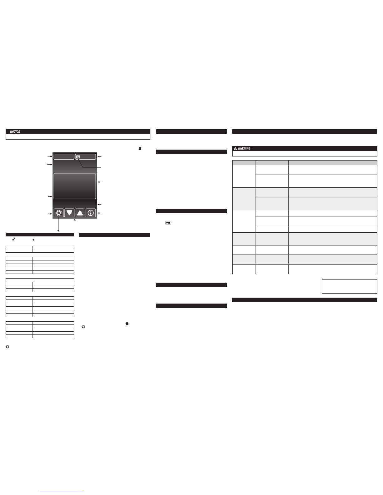
Touch the time, date or temperature to quickly a ccess settings. Advanced set tings are accessed by touching the S etting button.
Touch Screen Operation
74
°F
74
°F
Floor
Smart Start
Setpoint
6:27Fri, May 01
AM
HEATING
TESTRESET
Current date
Touch to change date and time
Schedule is enabled
Touch to change schedule
Operational status
Help screens
Use this button to read more about the setting
currently displayed. The active view will remain
after closing the help screen.
Adjust setting up or down
Menu Selection
Touch to view menu items
Smart Start
Displays if heating is on prior to a
schedule event time.
Current oor or room temp erature
The floor or room temperature 'Control' setting in
the 'Setup' menu determines which temperature
is displayed. 'Room Max' or 'Floor Max' appear
below if the target temperature is being limited
by another setting.
Current time
Touch to change date and time
Event status or setpoint
Touch to cycle between viewable items
Menus
TIME
Time & date Set the time and date
Options Time Format, Daylig ht Savings
SETUP
Floor Maximum 40 to 99 °F (4.5 to 37 °C)
Room Maximum 60 to 95 °F (15.5 to 35 °C)
Control Floor, Room
Set Floor Away OFF, 40 to 99 °F (4.5 to 37 °C)
Set Room Away OFF, 40 to 95 °F (15.5 to 35 °C)
SCHEDULE
Set Wake, Leave, Return, Sle ep event times and temperature s
New Program Create new program schedule
Smart Start Of f, On
Program Off, On
DIS PLAY
Temperature Units °F, °C
Brightness Wake/Return Off, 30 to 100%
Brightness Leave/Sleep Off, 30 to 100%
Display Theme L ight, Blue, Night, Latte, Espr esso
Languages English, Spanish, French
Clean Screen N o, Yes
TOOLBOX
Error Displays error me ssage if one exists
Heat Hours Displays operating hours
Room Offset -5 to +5 °
Software Versio n Displays type and soft ware version
Load Defaults Load factory defau lts into memory
IOM-ST-Command 1525
Power off SunStat. Touch disp lay for power on option.
HOME Exit menu system
Press
to accept. Press to return to the previous view.
The Display menu allows you to custo mize preferred display
units, brightness, c olor themes and language options. A Cl ean
Screen feature enables cleaning without affecting operation.
Set the time and date. Select 'O ptions' to access other settings.
Time format can be set to a 12- or 24-hr display. Automatic
daylight savings time can be se t to Off or On.
WARNING: This product contains chemicals known to the
State of California to cause cancer and birth defects or
other reproductive harm.
For more information: Watts.com/prop65
Error
• If there is curr ently an error, it will display as the first item.
Heat Hours
• Displays the he ating duration by day or month.
Room Offset
•
This feature can offs et operation to account for over or under
heating present at the sensor location.
Software Version
• Displays pro duct software version.
Load Defaults
• Select 'yes' to reload the factory default settings.
SunTouch Customer Support
USA Toll-free: (888) 432-8932
USA Fax: (417) 831-4067
Canada Toll-free: (888) 208-8927
Canada Fax: (905) 332-7068
Latin America Tel: (52) 81-1001-8600
Latin America Fa x: (52) 81-8000-7091
SunTouch.com
Watts Radi ant Customer Sup port
USA Toll-free: (800) 276-2419
USA Fax: (417) 864-8161
WattsRadiant.com
Canada Toll-free: (888) 208-8927
Canada Fax: (905) 332-7068
Watts.ca
 Loading...