

suntouch D12 series Installation Manual
D12 Series
There’s no easier way to heat a
floor than with SunTouch.
If you have any difficulties or
questions when installing our product,
just give us a call. We’re here to help!
88 88 88 -- 44 33 22 -- 88 99 33 22
ww ww ww .. ss uu nn tt oo uu cc hh .. nn ee tt
SSppaaccee WWaarrmmiinngg MMaannuuaall
36" width
24" width
12" width
Roll out the mat, make
your turns, fasten it
down, and set the tile!
SunTouch floor-warming mats have several great features
that make make any installation fast and easy.
• The S-pattern of SunTouch’s blue heating wire means
you can make both right and left turns easier and faster.
• SunTouch’s blue heating elements are tough and
resistant to jobsite abuse.
• SunTouch is the only electric floor-warming product
manufactured in America that registers no measurable
electromagnetic field (EMF)*.
• SunTouch comes with an armored “power lead” that
makes for a tougher and safer connection to the controls.
•With a slight change in the mat output, SunTouch
is now more efficient than ever.
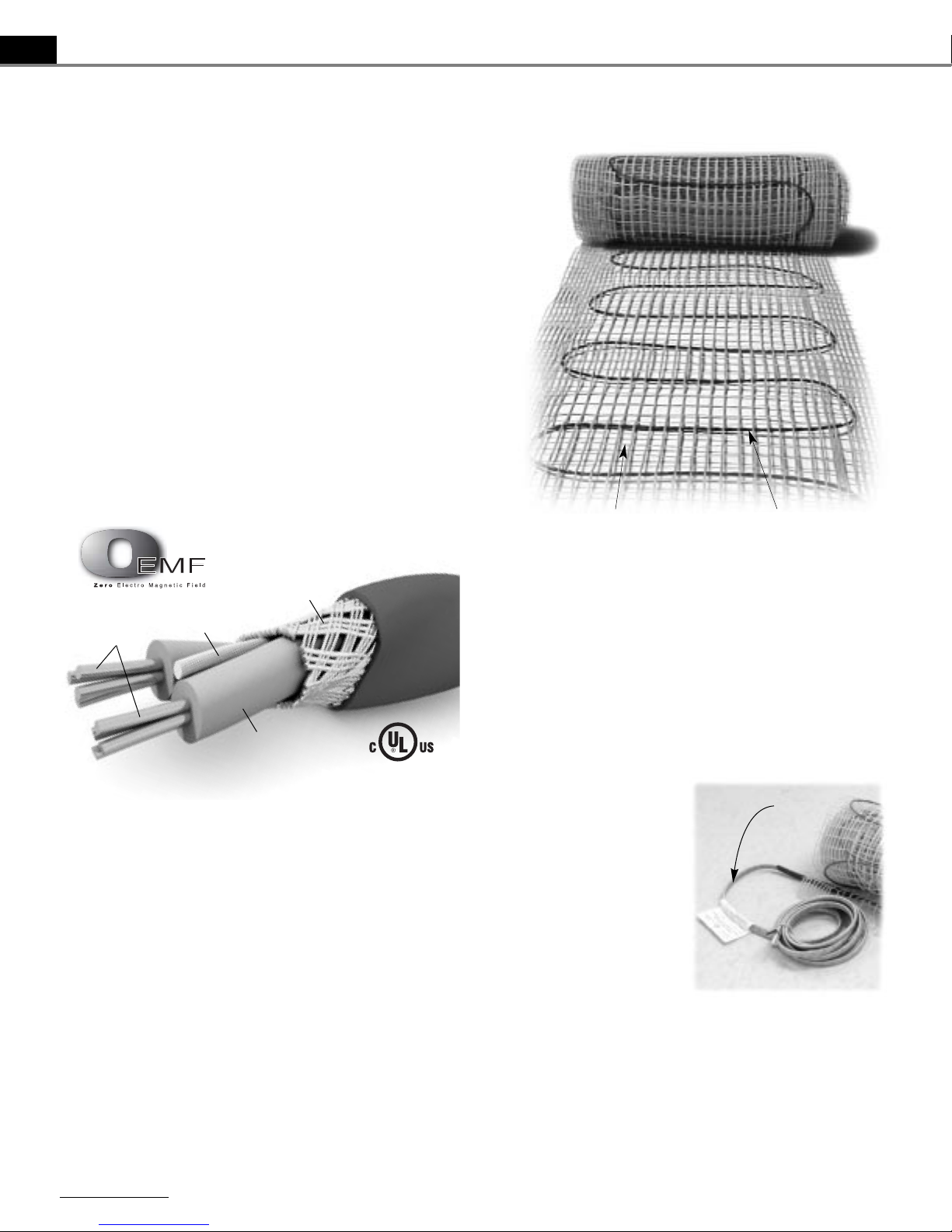
Orange woven mat
Blue heating wire
2 SunTouch Space Warming Manual
WWeellccoommee ttoo SSuunnTToouucchh!!
WWeellccoommee ttoo SSuunnTToouucchh!!
TThhee SSuunnTToouucchh MMaatt::
The blue heating wire is woven
into a special orange fiber to make rectangular mats. These
mats are manufactured for 120 VAC and 240 VAC, in 12",
24", and 36" widths. Mats range from 10 sq.ft. to 160 sq.ft.,
depending on width, length and voltage. Mats of different
dimensions must be wired together in parallel (not series) to
fill larger areas. However, they must be the same voltage. For
example, to warm an 80 sq.ft. area, many combinations are
possible: two 12" x 40' mats; or even a combination of one
24" x 20' and one 12" x 40'. Never combine 120 VAC mats
with 240 VAC mats.
SunTouch is a safe and efficient electric floor-warming
product for interior applications. It cannot be used for exterior
snowmelting applications. It is generally intended for installation below tile, stone, and other masonry flooring materials in
residential and moderate commercial installations. SunTouch
can be used to heat a room, as well as warm the floor, provided
the heat loss of the room falls below the mat’s capabilities.
Please refer to specific design information provided for heating applications, especially when installing non-masonry
flooring materials. The designer must determine if the output
of the SunTouch is enough heat to match the heat loss of
the structure.
SunTouch is designed to deliver 12 W/sq.ft. The floor temperature attainable is dependent on how well the floor is insulated, the temperature of the floor before start up, and in the
case of uninsulated slab applications, the thermal drain of the
underlying materials. Please refer to your designer if you have
further questions regarding the surface temperature you can
expect from SunTouch in your particular construction.
NNOOTTEE::
SunTouch has been tested to the American
Standard Test Method ASTM C627, a standard test method
for evaluating ceramic floor tile
installation systems using the
Robinson-Type Floor Tester.
This test was performed by
The Tile Council of America
for installation above a concrete
slab and above a framed floor.
This testing resulted in a rating
of “Moderate Commercial”
for normal (non-vehicular)
commercial and light institutional use. This would include
all (non-vehicular) residential use as well.
Never install SunTouch directly below vinyl, carpet,
or wood flooring. SunTouch must be embedded in mortar,
per UL requirements. Do not use glues or adhesives.
Non-masonry flooring materials such as carpet, vinyl, or
hardwood can be installed over SunTouch if the mat is
installed in a cement-based or gypsum-based material.
If you have any questions, please view our Installation
Video, visit our Web site at www.suntouch.net, or call us at
888-432-8932.
*When measured at 1/2" above floor surface with a field EMF meter. SunTouch Internal Test Labs results (not verified by UL).
Braided
Ground Shield
Heating
Elements
DuPont® Tefzel®
Core
DuPont® Tefzel®
Insulation
Hylar Cover
Enlarged, cutaway view of the blue heating wire.
AArrmmoorreedd
ppoowweerr lleeaadd

The primary components of the SunTouch system, depending
on the project requirements, are:
1. SunTouch mat*
2. Floor-sensing thermostat (programmable or
non-programmable)*
†
3. GFCI breaker (if not part of the thermostat)
4. External contactor (if required)
Other items needed:
• SunTouch Installation Kit* (shown below)
• Pneumatic stapler and hot glue gun
• 2-1/8" deep, 4" square electrical box for thermostat
• Single-gang “mud” (sheet rock) ring for 4" square box
• 12-gauge electrical wiring
• LoudMouth monitor*
•Digital ohm meter (multi-meter)
•Tile installation products (mortar, backer board, tile, etc.)
• 3/8" x 1/4" or greater trowel and other tile tools
•Various electrical and construction tools: (wire stripper,
screwdriver, chisel, scissors, etc.)
• Insulation (if required per design)
* Items available from SunTouch. All other items are not included and can
be purchased locally.
†
The FloorStat is approved for use in U.S. and Canada, separate from the
SunTouch Listed assembly.
NNEEVVEERR
install SunTouch under carpet, wood, vinyl, or
other non-masonry flooring without thin-set, thick-set,
or self-leveling mortar.
NNEEVVEERR
install SunTouch in any walls.
NNEEVVEERR
bang a trowel on the mat or blue wire to remove
excess mortar from it.
NNEEVVEERR
cut the blue heating wire.
NNEEVVEERR
cut the mats to make them shorter.
NNEEVVEERR
attempt to repair the blue heating wire if it is
damaged. Call the factory for further instruction.
NNEEVVEERR
install one mat on top of another or overlap the
mat on itself. This will cause dangerous over-heating.
NNEEVVEERR
install SunTouch in adhesives or glues intended
for vinyl tile or other laminate flooring. It must be
embedded in cement-based ceramic tile mortar.
NNEEVVEERR
forget to install the floor sensor (if using the
SunTouch FloorStat Control).
NNEEVVEERR
install mats under cabinets or other built-ins.
Excessive heat will build up under these items.
NNEEVVEERR
remove the nameplate label at the end of the mat.
AALLWWAAYYSS
enter mat resistance in the log before, during,
and after the installation process.
AALLWWAAYYSS
pay close attention to voltage and amp
requirements of the breaker, the thermostat, and the
SunTouch mat. For instance, do not supply 240 VAC
to 120 VAC SunTouch mats/thermostats.
AALLWWAAYYSS
make sure all electrical work is done by
qualified persons in accordance with local building
and electrical codes, Section 62 of the Canadian
Electrical Code (CEC) Part I, and the National
Electrical Code (NEC), especially Article 424, Part IX
of the NEC, ANSI/NFPA70.
AALLWWAAYYSS
use copper only as supply conductors.
AALLWWAAYYSS
affix the warning label (included with this
manual) to the control cover plate or other location
where it is easily noticed.
AALLWWAAYYSS
seek our help if you have a problem. If you are
ever in doubt about the correct installation procedure to
follow, or if the product appears to be damaged, you
must call us before proceeding with the installation, or
proposed repair.
If you have any questions, please view our Installation
Video, visit our Web site at
wwwwww..ssuunnttoouucchh..nneett
, or call us
at
888888--443322--88993322
.
CAUTIONS!
READ BEFORE INSTALLING SUNTOUCH
SunTouch Installation Kit
SunTouch Space Warming Manual 3
HHeerree’’ss WWhhaatt YYoouu’’llll NNeeeedd::
IInnssttaallllaattiioonn VViiddeeoo
IInnssttaallllaattiioonn MMaannuuaall
DDoouubbllee--ssiiddeedd
TTaappee
3300 CClliippss
1100
NNaaiillTTiitteess
Mat Serial Number
Mat Size
Mat Voltage
Factory Mat Resistance Range
OOUU TT OOFF TTHHEE BBOOXX BBEEFFOO RREE IINNSSTTAALLLLAATTIIOONN ((oohhmmss))
Mat black to white
Mat black to green
Mat white to green
AAFFTTEERR MMAATT IISS FFAASSTTEENNEEDD TTOO FFLLOOOORR (( oohhmmss))
Mat black to white
Mat black to green
Mat white to green
AAFFTTEERR TTIILLEE//SSTTOONNEE IISS IINNSSTTAALLLLEEDD OOVVEERR TTHHEE MMAATT ((oohhmmss))
Mat black to white
Mat black to green
Mat white to green
RReettaaiinn tthhiiss lloogg ffoorr wwaarrrraannttyy!! DDOO NNOOTT DDIISSCCAARRDD!!
CChheecckk oouutt tthhaatt wwiirree!!
Throughout the installation process
it is very important to take resistance
readings of the mat to make sure it is
not damaged. Use a quality digital
ohmmeter or multimeter to make these
measurements. Analog meters (with
the moving needle) are not accurate
for this product.
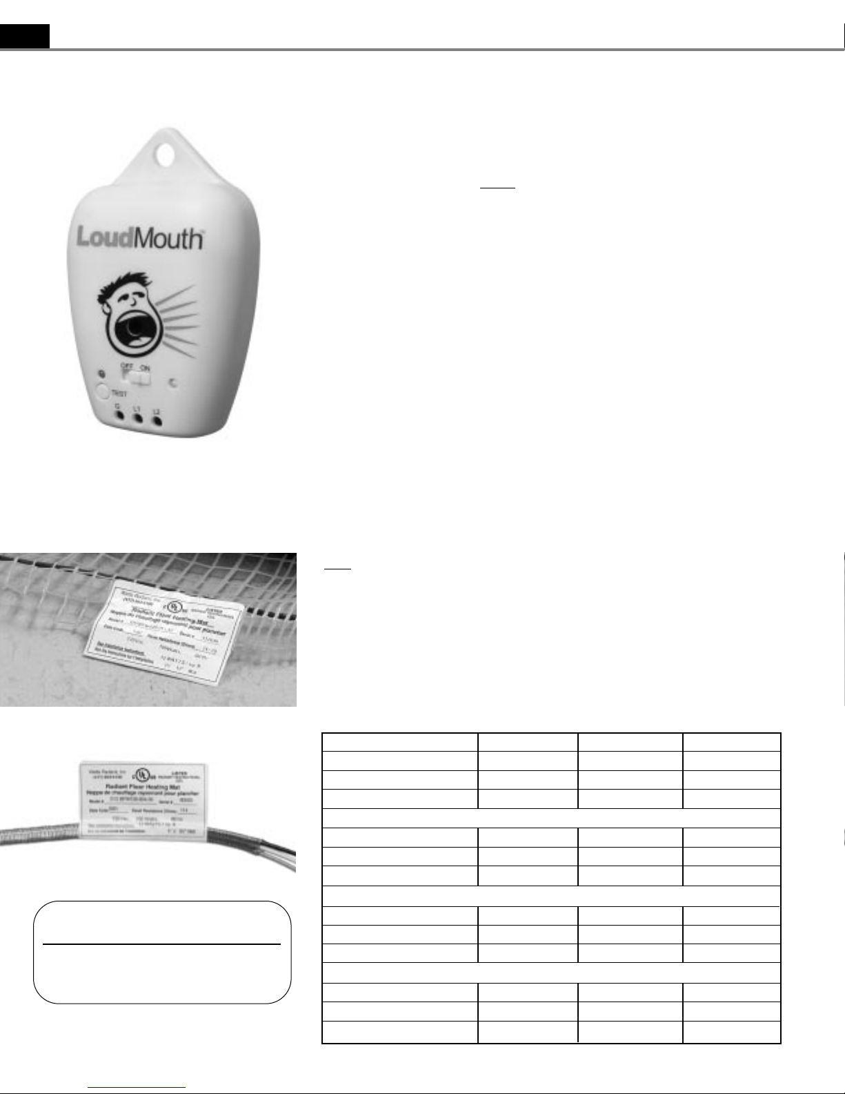
The LoudMouth™monitor shown
at left will help constantly monitor
the mat for you during the entire
installation. Ask about purchasing this
invaluable tool.
EEsssseennttiiaall PPrroodduucctt aanndd
WWaarrrraannttyy IInnffoorrmmaattiioonn
There is a factory-applied nameplate
label at the end of the mat and also on
the cold leads as shown at lower left.
Do not remove these. Record the mat
serial number, mat size, voltage, and
panel resistance range on the table
below for each mat.
To retain the Limited Warranty as
stated at the back of this manual, these
items and the following measurements
must
be recorded, as well as all steps
of this manual followed. Refer to the
Limited Warranty now for complete
requirements.
MMeeaassuurreemmeennttss
Make the following measurements
(as a minimum)
• before you begin installation
• after the mat is fastened to the floor
• after floor coverings are installed
Also, checking these measurements
often during tile installation is highly
recommended to avoid burying a
damaged wire.
CChheecckkiinngg ffoorr bbrreeaakkss
Measure resistance between the
black and white leads (black and blue
leads for 240V mats) and record this
below. This measurement should be
within the Mat Resistance range shown
on the nameplate label, or if the label
gives only a single number it must be
within ±10%. A cut or break in the
wire is indicated by a resistance of
“infinite” ohms (no continuity).
CChheecckkiinngg ffoorr sshhoorrtt--cciirrccuuiittss
Measure resistance between the
black and green leads and between the
white and green leads (blue and green
leads for 240V mats) and record these
below. This measurement should be
“infinite” ohms (no continuity). Acut
or pinch in the wire is indicated by a
resistance value between zero and the
mat resistance.
If the resistance is not correct, or if
you cut or damage the wire, quickly
clean up the damaged area and call the
factory for further instructions.
UUssee OOuurr LLoouuddMMoouutthh MMoonniittoorr..
We created the LoudMouth to monitor the
mat during the installation process. If the mat is
cut or damaged during installation, this device
sounds an alarm. The LoudMouth will prevent
you from burying damaged wire below
hardened mortar and tile or stone.
Record the information from this nameplate
label in the Mat Resistance Log at right.
The electric radiant heating warning label
must be placed near, or on the face of the
mat control.
Radiant Floor Heating Mat
Warning-Risk of electric shock
Electric wiring and heating panels
contained below the floor.
Do not penetrate floor with nails, screws,
or similar devices.
Leave this nameplate on the power
leads for later inspection.
4 SunTouch Space Warming Manual
CChheecckk hheeaattiinngg wwiirree rreessiissttaannccee bbeeffoorree iinnssttaallllaattiioonn..
MMaatt RReessiissttaannccee LLoogg

SSTTEEPP 11..11::
IInnssttaallll GGFFCCII BBrreeaakkeerr
((OOvveerrccuurrrreenntt PPrrootteeccttiioonn))
The SunTouch mat must be pro-tected by a ground fault circuit interrupter
(GFCI). This can be done either by the
internal GFCI in the SunTouch FloorStat
(as long as it directly controls the mat)
or an indicating-type GFCI
circuit breaker. This GFCI serves as a
local disconnect.
Note: Follow all local building and
electrical codes.
Note: It is possible to branch from
an existing circuit, but this is not
recommended. Please consult with a
qualified electrician to determine if
the circuit can handle the load and
if the circuit is GFCI-protected.
The size of the breaker is determined
by the total square footage of heating
mat. (Depending on local codes, you
may need multiple breakers for systems
larger than 20 amps.)
Typical Amperage Requirement:
120 VAC SunTouch mats:
0.1 amps per sq.ft., or
10 amps per 100 sq.ft. of mat.
240 VAC SunTouch Mats:
0.05 amps per sq.ft., or
5 amps per 100 sq.ft. of mat.
SSTTEEPP 11..22::
IInnssttaallll EExxtteerrnnaall
CCoonnttaaccttoorr ((rreellaayy))
Depending on the amperage requirements of the mat(s), an external contactor may be required. Consult with an
electrician to determine the type and size
of contactor. Do not load the FloorStat
control with more than 15 amps. Be sure
to protect this contactor circuit with a
GFCI breaker.
SSTTEEPP 11..33::
IInnssttaallll EElleeccttrriiccaall
BBooxxeess
Thermostats are usually located near
the power leads. However, they can
be located almost anywhere, because
the power leads and the sensor wire can
be routed to electrical junction boxes
and extended to a location outside the
heated room (such as a utility room or
basement).
TThheerrmmoossttaatt::
Install a 4"-square,
2-1/8" deep electrical box with a
1-gang mud ring. Electrical boxes
should be located on interior walls, typi-
cally 60" from the floor, according to
NEC or other local code requirements.
Note: The FloorStat sensor wire
can be extended up to a maximum of
50', if necessary.
SSTTEEPP 11..44::
BBoottttoomm PPllaattee WWoorrkk
Drill or saw holes at the bottom plate
as indicated at right. One hole is for
routing the power leads or conduit and
the other is for the thermostat sensor.
These holes should be directly below the
electrical box(es) (see photos at right).
SSTTEEPP 11..55::
IInnssttaallll PPoowweerr LLeeaadd
CCoonndduuiitt aanndd TThheerrmmoossttaatt SSeennssoorr
PPoowweerr LLeeaadd CCoonndduuiitt::
The armored
power lead can be installed with or without electrical conduit depending on code
requirements. In either case, remove one
of the knock-outs in the 4" box to route
the lead. If electrical conduit is not
required by code, install a wire collar to
secure the leads where they enter the
box. If conduit is required by code,
install 1/2" (minimum) conduit from the
bottom plate up to the electrical box. For
multiple power leads (multiple mats)
install 3/4" conduit, which will accommodate multiple power leads.
TThheerrmmoossttaatt SSeennssoorr::
A floor sensor
comes with our FloorStat control. It can
be installed in a conduit separate from
the electrical power lead although this is
not necessary. If a conduit is installed,
the tip of the conduit should be metallic
in order for the sensor to give a true
temperature reading. Open a second
knock-out in the bottom of the thermostat box. Feed the sensor (and conduit)
through the knock-out, down through the
cut-out in the bottom plate, and out into
the floor where the heating mat will be
installed. If you have the thermostat and
sensor, install the sensor now, but wait
to install the thermostat until after the
mat is installed.
Note: The sensor is located in the
thermostat packaging.
SSTTEEPP 11..66::
RRoouugghh--iinn WWiirriinngg
Install appropriate electrical wire
(conductor) from the power source and
breaker protection to the thermostat following all codes. Leave 6"–8" extra wire
at the thermostat box. Refer to the
Typical Wiring Diagrams at the end of
this manual for help.
MMaatt AAmmppeerraaggee RReeqquuiirreemmeennttss
Mat Size Square Footage Amp Draw
112200 VVAACC,, 1122""--wwiiddee mmaatt
12" x 10' 10 sq. ft. 1.0
12" x 15' 15 sq. ft. 1.5
12" x 20' 20 sq. ft. 2.0
12" x 25' 25 sq. ft. 2.5
12" x 30' 30 sq. ft. 3.0
12" x 35' 35 sq. ft. 3.5
12" x 40' 40 sq. ft. 4.0
12" x 45' 45 sq. ft. 4.5
12" x 50' 50 sq. ft. 5.0
112200 VVAACC,, 2244""--wwiiddee mmaatt
24" x 5' 10 sq. ft. 1.0
24" x 10' 20 sq. ft. 2.0
24" x 15' 30 sq. ft. 3.0
24" x 20' 40 sq. ft. 4.0
24" x 25' 50 sq. ft. 5.0
24" x 30' 60 sq. ft. 6.0
24" x 35' 70 sq. ft. 7.0
24" x 40' 80 sq. ft. 8.0
112200 VVAACC,, 3366""--wwiiddee mmaatt
36" x 5' 15 sq. ft. 1.5
36" x 6'8" 20 sq. ft. 2.0
36" x 8'4" 25 sq. ft. 2.5
36" x 10' 30 sq. ft. 3.0
36" x 15' 45 sq. ft. 4.5
36" x 20' 60 sq. ft. 6.0
______________________________________________
224400 VVAACC,, 1122""--wwiiddee mmaatt
12" x 20' 20 sq. ft. 1.0
12" x 30' 30 sq. ft. 1.5
12" x 40' 40 sq. ft. 2.0
12" x 50' 50 sq. ft. 2.5
224400 VVAACC,, 2244""--wwiiddee mmaatt
24" x 10' 20 sq. ft. 1.0
24" x 15' 30 sq. ft. 1.5
24" x 20' 40 sq. ft. 2.0
24" x 25' 50 sq. ft. 2.5
24" x 30' 60 sq. ft. 3.0
24" x 35' 70 sq. ft. 3.5
24" x 40' 80 sq. ft. 4.0
24" x 45' 90 sq. ft. 4.5
24" x 50' 100 sq. ft. 5.0
24" x 60' 120 sq. ft. 6.0
24" x 70' 140 sq. ft. 7.0
24" x 80' 160 sq. ft. 8.0
224400 VVAACC,, 3366""--wwiiddee mmaatt
36" x 10' 30 sq. ft. 1.5
36" x 13'4" 40 sq. ft. 2.0
36" x 16'8" 50 sq. ft. 2.5
36" x 20' 60 sq. ft. 3.0
36" x 30' 90 sq. ft. 4.5
36" x 40' 120 sq. ft. 6.0
PPhhaassee 11.. EElleeccttrriiccaall RRoouugghh--iinn..
RReeffeerr ttoo aallll ddrraawwiinnggss oonn ppaaggeess 1111,, 1166,, aanndd 1177 bbeeffoorree bbeeggiinnnniinngg eelleeccttrriiccaall wwoorrkk..
SunTouch Space Warming Manual 5
Power lead
conduit
Power
lead
conduit
Floor sensor
conduit
Power lead
NailTite
Wire Clip
Sensor wire
Power lead
Sensor
wire
SSTTEEPP 22..11
SSeelleecctt TTyyppee ooff CCoonnssttrruuccttiioonn
Choose the best thin-set, thick-set, or selfleveling mortar installation detail for your
application. Consult with building professionals and/or SunTouch personnel for specific
details concerning proper installation.
SSTTEEPP 22..22
FFlloooorr PPrreeppaarraattiioonn
The floor must be completely swept of
all debris including all nails, dirt, wood, and
other construction debris. Make absolutely
sure there are no objects on the floor that
might damage the SunTouch wire.
SSTTEEPP 22..33
SSttuuddyy tthhee FFaaccttoorryy--ssuupppplliieedd
IItteemmss aanndd tthhee DDeessiiggnn
Make sure all of the correct materials have
been purchased. Ageneral list of materials
is found at the beginning of this manual.
Study the design carefully before installation. Review the thermostat location and
where the mat begins and ends, as well as the
general layout pattern.
Do not cut the wire or shorten the
mat to make it fit the space. Doing so
will cause dangerous overheating and
will void the warranty!
SSTTEEPP 22..44
MMoorrttaarr aanndd TThhiinn--SSllaabb AApppplliiccaattiioonnss
SunTouch can be installed in two types of
construction applications:
1. Thin-set or thick-set mortar beds (3/8"–1").
2. Self-leveling mortar beds (1/4"–1/2").
No matter the application, always install
SunTouch before installing mortar or cement.
Do not lay SunTouch in wet mortar.
We strongly recommend installing tile and
stone flooring according to manufacturer’s
recommendations, TCA guidelines, and ANSI
specifications.
If installing non-masonry floor coverings,
such as hardwood, vinyl, laminate or carpet,
follow industry and manufacturer’s recommendations.
If installing non-masonry coverings
, the
best method is cover the SunTouch in a selfleveling mortar (illustrations #5 and #6).
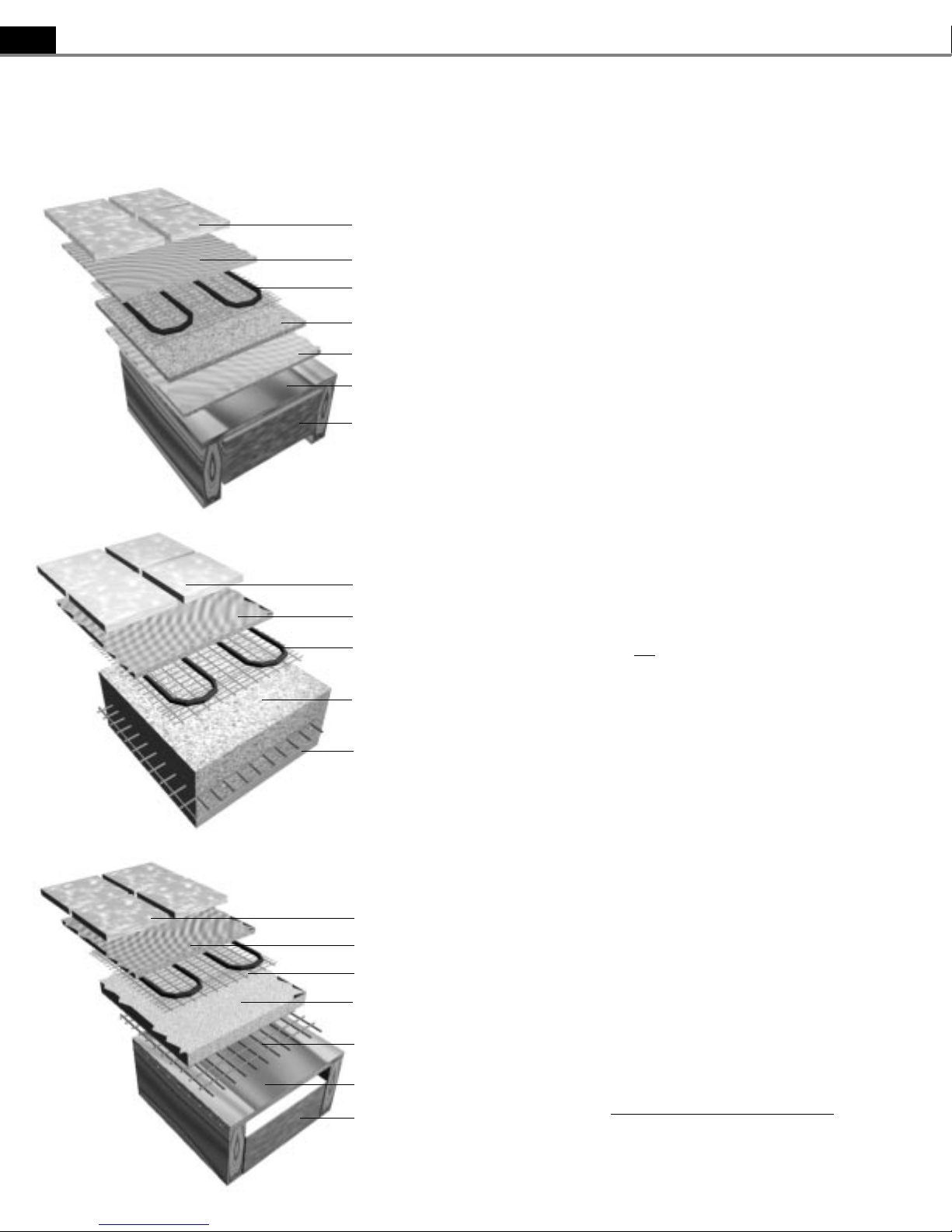
MMOORRTTAARR AAPPPPLLIICCAATTIIOONNSS
Insulation (per International
Residential Code, Chapter 11)
Insulation (per International
Residential Code, Chapter 11)
Latex-Portland cement mortar
bond coat
11.. TTHHIINN--SSEETT MMOORRTTAARR OOVVEERR FFRRAAMMEEDD FFLLOOOORR
(Dry-set or latex cement mortar; TCA #F144-2K)
SunTouch
Backer board
Mortar bed
Plywood
Tile/stone
SunTouch
Slab
Latex-Portland cement mortar
bond coat
Tile/stone
22.. TTHHIINN--SSEETT MMOORRTTAARR OOVVEERR SSLLAABB
(Dry-set or latex cement on slab; TCA #113-2K)
33.. TTHHIICCKK--SSEETT CCEEMMEENNTT MMOORRTTAARR MMEETTAALL LLAATTHH
(Cement mortar metal lath; TCA #145-2K)
Tile/stone or laminate flooring
Latex-Portland cement mortar bond coat
SunTouch
Mortar bed
Metal lath
Plywood
Insulation (per International
Residential Code, Chapter 11)
6 SunTouch Space Warming Manual
PPhhaassee 22.. SSuunnTToouucchh IInnssttaallllaattiioonn..
 Loading...