

Page 1
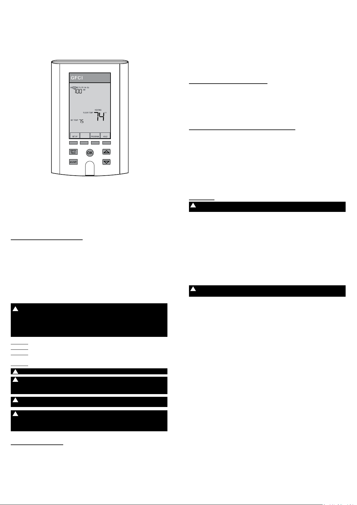
Owner’s Manual
SunStat® Pro II
Programmable Thermostat
Model 500775
The SunStat Pro II model 500775 is designed to operate either a 120 VAC or
240 VAC resistance oor heang system. It comes with an easy setup wizard, a
typical program ready to go, and a GFCI inside to meet safety needs.
Please follow this manual for installaon and operang instrucons. Leave these
instrucons with the homeowner.
Installaon
Cautions to Follow
You are required to thoroughly read all installaon instrucons and product
safety informaon before beginning the installaon of this product. FAILURE
TO COMPLY WITH PROPER INSTALLATION AND MAINTENANCE INSTRUCTIONS
COULD RESULT IN DAMAGE TO THE SYSTEM OR ELECTRIC SHOCK CAUSING
PROPERTY DAMAGE, PERSONAL INJURY AND/OR DEATH. Was is not
responsible for damages resulng from improper installaon and/or
maintenance.
Local building or plumbing codes may require modicaons to the informaon
provided. You are required to consult the local building and plumbing codes
prior to installaon. If this informaon is not consistent with local building or
plumbing codes, the local codes should be followed.
CAUTION: This product requires electrical wiring. It is recommended that
!
this product is installed by a qualied technician. Local codes may require
this product be installed by an electrician. Prior to installaon, consult
your local codes for what is acceptable in your area. To the extent this
informaon is not consistent with local codes, the local codes should be
followed.
ALWAYS: Wire all circuits as Class 1, Electric Light and Power Circuits
ALWAYS: Wire all circuits with insulaon rated 600V minimum.
ALWAYS: Mount this control only to a grounded metallic box or a nonmetallic
box.
ALWAYS: Use power supply wires suitable for at least 90°C.
!
WARNING: High voltage – disconnect power supply before servicing.
!
WARNING: The GFCI (ground-fault circuit interrupter) in this thermostat
control does not protect against shock if both bare conductors are touched
at the same me.
WARNING: Do not exceed 15 amps on this thermostat control. Doing so will
!
cause risk of re hazard and damage.
CAUTION: Make sure the house power supply voltage matches the voltage
!
rang of the oor heang system. Do not apply 240 VAC to a 120 VAC rated
system. Connecng the wrong voltage may cause overheang and damage
to the system, the control, oor coverings, etc.
Parts Needed
Contents of package:
Unpack the thermostat control and make sure everything is in good condion.
Do not use a damaged control or part. The package comes with these items:
(1) Thermostat
(1) Thermostat oor sensor
(4) Wire nuts (Marees®)
(2) Mounng screws
(1) Screwdriver
Tools and supplies needed:
- No. 2 Phillips screwdriver
- Hole saw (if installing in an exisng wall)
- Wire strippers, wire cuers, and other electrical tools
- Electrical wall box (plasc or metal)*
*NOTE: A single-gang extra-deep box allows sucient space to connect 1 or 2
heang mats or cables. For 3 heang mats or cables, a 4-inch square extra-deep
electrical box with a single-gang “mud ring” is necessary. Alternately, a juncon
box may be installed to connect mulple heang mats or cables, then run
power supply wire from the juncon box to the control electrical box. See the
Installaon Instrucons provided with the oor heang system for more details.
Locang the Control
Find a suitable locaon for the control. It is designed for indoor dry locaon only.
It may be placed on an insulated or uninsulated wall, preferably an interior wall
to avoid overheang from outside sun heat. Keep it away from all water sources
such as sinks, showers, and bathtubs as well as heat sources such ashot-water
piping, heat ducng, wall-mount lighng, and direct sunlight. Locate it at a
suitable height, normally about 4-1/2’ to 5’ (1.4 m to 1.5 m) from the oor.
Mounng the Electrical Box
When mounng on an exisng wall, cut the opening for the electrical box for the
control. To make it easier to pull the wiring, wait to install the electrical box unl
aer all wiring is drawn into this opening.
When mounng on an open wall, secure the electrical box for the control to the
wall stud.
When mounng on an open wall, conduit from the electrical box to the oor is
recommended (check local codes for requirements) for addional protecon.
Install one conduit for the oor sensor. Install another conduit for the oor
heang system power leads. Refer to the Installaon Instrucons supplied with
the oor heang system for addional installaon details.
Wiring
CAUTION: Turn o power at the circuit breaker before doing any
!
electrical work.
House Wiring
A qualied person should run a dedicated circuit from the main circuit breaker
panel to the control locaon. If a dedicated circuit is not possible, it is acceptable
to tap into an exisng circuit. However, there must be enough capacity to handle
the load (amps) of the oor heang system being installed and any possible
appliance, such as a hair dryer or vacuum cleaner. Avoid circuits that have
ballasted lighng, motors, exhaust fans, or hot tub pumps due to
possible interference.
The circuit breaker should be rated 20 amps for total circuit loads up to 15 amps.
A 15 amp circuit breaker may be used for total circuit loads up to 12 amps. A
GFCI (ground-fault circuit interrupter) or AFCI (arc-fault circuit interrupter) type
circuit breaker may be used if desired, but is not necessary.
WARNING: Do not exceed 15 amps on this thermostat control. Doing so will
!
cause risk of re hazard and damage.
Pull power supply wiring to the control locaon. Leave about 6 to 8 inches (15
to 20 cm) of wire for connecons later. This wiring should be size 12 or 14 AWG
following appropriate local code requirements.
Floor Sensor
Pull the oor sensor wire up the wall (or conduit) to the control locaon, leaving
about 6 inches (15 cm) of wire for connecon later. The sensor wire may be cut
shorter if desired, but do not cut it shorter unl the sensor is fully installed
(see below).
Note: If the sensor wire is not long enough to reach the control locaon, it may
be extended an addional 15 feet (4.5 m) using minimum 20 AWG 2-conductor
unshielded wire, or an addional 50 feet (15 m) using shielded wire. When
using shielded wire, the “shield” must be connected to the lower sensor
terminal, nearest to Bus A. A juncon box may be required by local code for the
connecon to this extension wire.
Aer the oor heang system is completely installed according to its
instrucons, secure the thick sensor p to the oor. It must be located halfway
between heang wires and at least 1 foot into the heang area. Use hot-glue to
secure the sensor p and wire in place. Do not cross over a heang wire. Avoid
placing it in an area where heang wires are spaced further apart than the rest
of the oor, like a large gap between mats or cables. Avoid placing it in an area
where a heat duct or recessed light will cause improper measurements. Try to
avoid locang it where future items such as a clothes hamper or similar could
trap heat and cause improper measurement.
Finish securing the sensor wire along the oor and up the wall. At the control
locaon, cut the sensor wire shorter if needed, leaving at least 6 to 8 inches (15
to 20 cm) of wire for connecons later. Re-strip the sensor wire ends 1/8” to
3/16” (3 mm to 4.5 mm) long. If the ends are stripped longer than this they may
short-circuit resulng in an Err2 code.
Mat or Cable Power Leads
Pull the power lead wires from the oor heang system into the control
locaon. Leave about 6 to 8 inches (15 to 20 cm) of wire for connecons.
Page 2
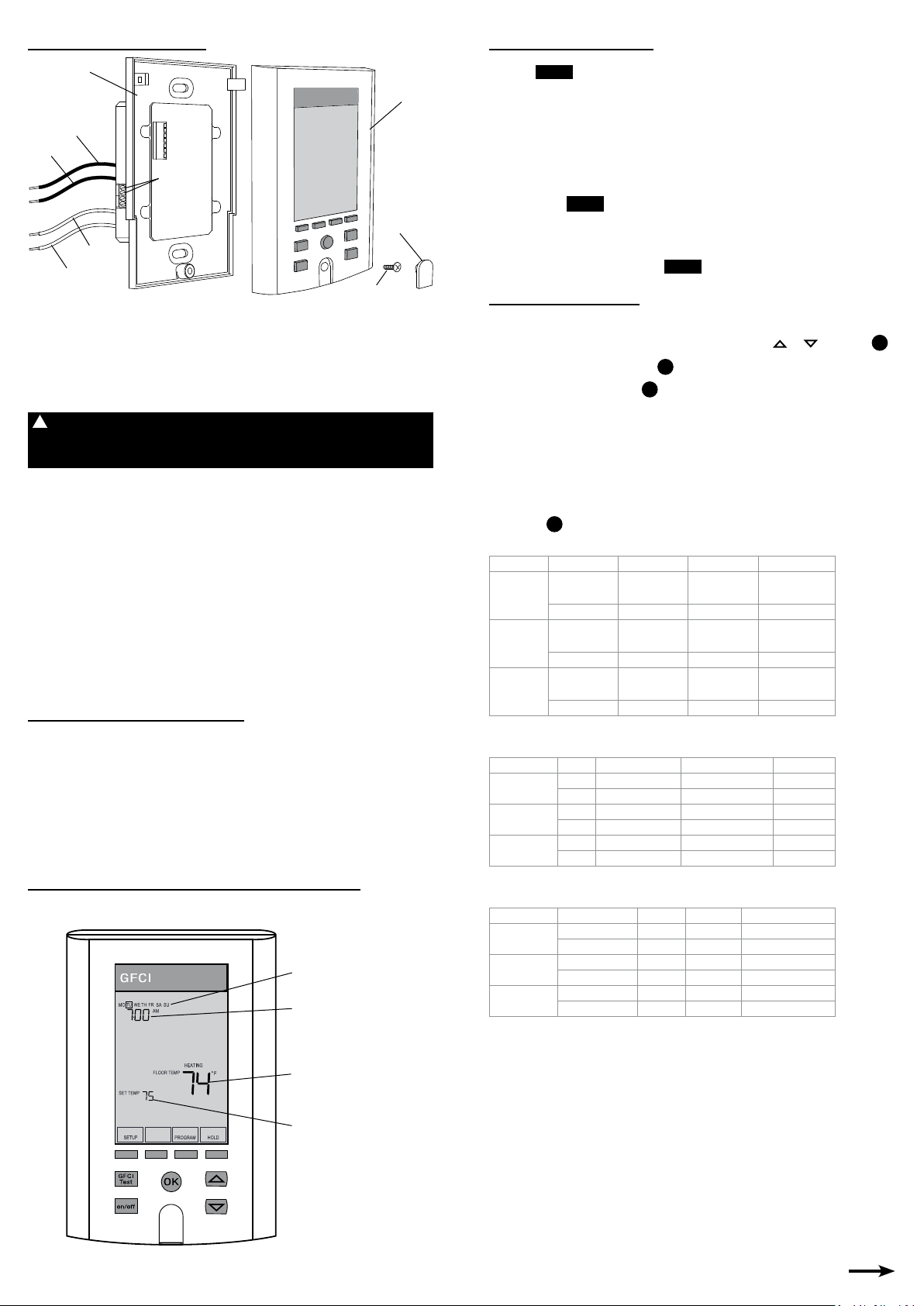
Wire Connecons
Power Module
Front Module
Load 1
Line 1
Floor Sensor
Connecon
Screw Cover
Line 2
Load 2
Cover Screw
Match and connect the two wires marked “LINE1(L)” and “LINE2(N)” to the
house power supply wires using the wire nuts provided. Gently tug on the wires
to make sure they are secure, otherwise a wire could come loose and cause
failure. For added security, overwrap the connecons with electrical tape.
Match and connect the two wires marked “LOAD1” and “LOAD2” to the power
lead wires from the oor heang system. Secure these wire connecons the
same way with the appropriate size wire nut for the number of wire connected.
CAUTION: Make sure the house power supply voltage matches the voltage
!
rang of the oor heang system. Do not apply 240 VAC to a 120 VAC rated
system. Connecng the wrong voltage may cause overheang and damage
to the system, the control, oor coverings, etc.
Connect the house ground wire to the ground wire(s) from the oor heang
system. If the electrical box is metal, a short length of wire must be secured to
the electrical box from this ground connecon.
Insert the ends of the oor sensor wire into the terminals marked “SENSOR” and
snug the screws. It does not maer which wire goes into which terminal
SunStat Relay (oponal)
Read and follow the instrucons provided with the SunStat Relay.
Pull 18 AWG to 24 AWG 2-conductor shielded wire through the wall from the
SunStat Relay locaon to this control locaon. This wire may be up 100 feet (30
m) in length. Strip the wire ends 1/8” to 3/16” (3 mm to 4.5 mm) long. If the
ends are stripped longer than this they may short-circuit.
Connect the wire ends into the “BUS” A and B terminals. Make sure the wire in
“A” terminal is connected to an “A” terminal in the SunStat Relay.
Mounng the Control
Carefully press the wires back into the electrical box. Do not use the control to
push them in, as this may cause connecons to loosen and possible failure.
Loosen the screw and remove the front module from the power module. Secure
the power module into the electrical box with the mounng screws provided.
Snap the front module onto the power module and ghten the screw. Press the
Screw Cover in place to cover screw.
Operaon
Overview of Features and Display
Press a buon if the display is dark. This wakes the display backlight.
Day
Time
On/O and GFCI
On/O and Reset
Pressing will turn the thermostat on or o. This also Resets
the thermostat to clear an error or GFCI fault. See “GFCI Tesng” and
“Troubleshoong”.
on/o
GFCI Tesng
The GFCI (Ground Fault Circuit Interrupter) in this control must be tested when
installaon is nished and once each month.
• Make sure the control shows it is Heang. This may require temporarily
increasing the setpoint temperature.
• Press the buon. GFCI TRIP should be indicated on the control.
There will also be a click sound, indicang power has been removed from
the oor heang system. If either of these indicaons fail, turn o the
thermostat and replace it. Do not connue to use.
• To reset the GFCI TRIP, press
GFCI
Tes t
on/o
o and back on.
Startup Wizard
This thermostat comes with a “wizard” to help the user through basic setup.
• When rst powered up, or upon reseng the factory defaults, the display
will ask to set the year. Adjust the year by pressing
OK
OK
.
.
• Select the month and press
• Select the day and press
• Set the hour and minutes (format is 12-hour clock but this can be changed
to a 24-hour clock). See Changing Sengs Secon.
• Select the sensing method (Floor or Air). Default is Floor. See cauons
before using the Air Sensing method. See Changing Sengs Secon.
• Select a program schedule. The default is called “Normal Day” where it
makes the oor warmer during morning and evening hours. Any of the
schedules can be customized to t your needs.
OK
• Press
and the thermostat will begin working automacally.
NORMAL DAY
Cycle WAKE LEAVE RETURN SLEEP
Monday –
Friday
Saturday
Sunday
NOTE: Air Sensing mode default temperatures are 70F and 62F.
6:00 AM
(6:00)
82 F (27.8 C) 74 F (23.3 C) 82 F (27.8 C) 74 F (23.3 C)
7:00 AM
(7:00)
82 F (27.8 C) 74 F (23.3 C) 82 F (27.8 C) 74 F (23.3 C)
7:00 AM
(7:00)
82 F (27.8 C) 74 F (23.3 C) 82 F (27.8 C) 74 F (23.3 C)
8:00 AM
(8:00)
9:00 AM
(9:00)
9:00 AM
(9:00)
5:00 PM
(17:00)
5:00 PM
(17:00)
5:00 PM
(17:00)
WARM ALL NIGHT
Cycle WAKE LEAVE RETURN SLEEP
Monday –
Friday
Saturday
Sunday
NOTE: Air Sensing mode default temperatures are 70F and 62F.
-- 8:00 AM (8:00) 5:00 PM (17:00) --
-- 74 F (23.3 C) 82 F (27.8 C) --
-- 9:00 AM (9:00) 5:00 PM (17:00) --
-- 74 F (23.3 C) 82 F (27.8 C) --
-- 9:00 AM (9:00) 5:00 PM (17:00) --
-- 74 F (23.3 C) 82 F (27.8 C) --
HOME DURING DAY
Cycle WAKE LEAVE RETURN SLEEP
Monday –
Friday
Saturday
Sunday
NOTE: Air Sensing mode default temperatures are 70F and 62F.
6:00 AM (6:00) -- -- 10:00 PM (22:00)
82 F (27.8 C) -- -- 74 F (23.3 C)
7:00 AM (7:00) -- -- 11:00 PM (23:00)
82 F (27.8 C) -- -- 74 F (23.3 C)
7:00 AM (7:00) -- -- 11:00 PM (23:00)
82 F (27.8 C) -- -- 74 F (23.3 C)
or and press
10:00 PM
(22:00)
11:00 PM
(23:00)
11:00 PM
(23:00)
OK.
Floor temperature
Setpoint temperature
Page 3
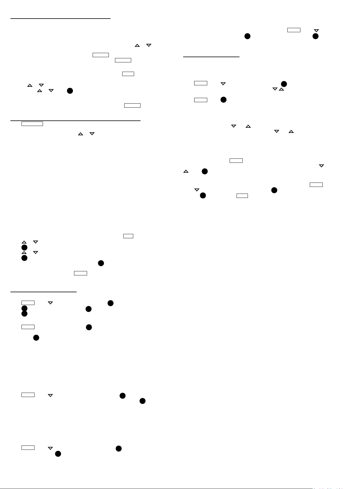
Adjusng the Temperature
Normally the thermostat will run automacally based on the programmed
sengs. However, these sengs may be overridden temporarily or for a
specied period of me.
Overriding Temporarily
To only override the program unl the next scheduled me, press or to
select the desired setpoint temperature. Aer a few seconds it will indicate
“HOLD SET TEMP UNTIL NEXT PERIOD” and
override and return to normal scheduled sengs press
Holding the Override
To override the program for a specic period of me, press
whether to set this for a Connuous Hold or for a certain number of days by
pressing
then pressing
the Hold seng. The thermostat will operate at the setpoint temperature
connuously or for the number of days selected before returning to normal
schedule sengs. This feature may be cancelled by pressing
or . The number of days can be adjusted by selecng EDIT and
or . Press OK to save this selecon. The display will show
CANCEL
will show. To cancel this
CANCEL
HOLD
CANCEL
.
. Select
.
Customizing the Program Schedule
Press
PROGRAM
the top of the display. This is a 7-day programmable thermostat, allowing each
day to have its own schedule. Press or to browse through each day(s)
schedule.
How does a schedule work?
Example:
• To have the oor warm up to 82F at 6:00 AM in the morning, set the WAKE
period to these values.
• To save energy and allow the oor to cool to 74F aer leaving at 8:00 AM,
set the LEAVE period to these values.
• To have the oor warm again to 82F when returning home at 5:00 PM, set
the RETURN period to these values.
• Finally, to save energy overnight and cool the oor to 74F aer 10:00 PM,
set the SLEEP period accordingly.
NOTE: With the SmartStart feature turned on (see SmartStart below), the
thermostat will learn how long it takes the oor to reach 82F and begin warming
up a lile early, reaching 82F by the WAKE me 6:00 AM and again at the
RETURN me 5:00 PM.
Modifying the schedule
To modify the schedule, select the period desired and press
Press or to adjust the me.
OK
Press
Press or to adjust the temperature.
OK
Press
Select another schedule to be edited, or press
NOTE: To clear a period, useful if you want to only raise and lower the oor
temperature once in a day, select
period in the schedule. There must be two periods in the schedule.
. The schedule shown is set for the highlighted day shown at
to save.
to save.
CLEAR
OK
to return to the home screen.
. The thermostat will skip over this
EDIT
.
reaching the setpoint temperature at the scheduled me. For example, the
schedule may have a “WAKE” start me of 6:00AM to be 82F (27.8C) and
SmartStart may begin pre-heang at 5:30AM to reach 82F by 6:00AM.
If this feature is not desired, it may be turned o. Press
select “SMARTSTART” and press
and return to the home screen.
OK
. Select “ON” or “OFF” and press
SETUP
. Press to
OK
to save
Other Features
Usage
The thermostat stores in memory the number of hours that it is heang.
This informaon may be useful in calculang the energy used by the oor
heang system.
SETUP
Press
number of hours it was heang today. Pressing will show the number of
hours it was heang the last 7 days and 30 days. To reset these counters to zero,
press
. Press to select “USAGE” and press
OK
CLEAR
. Press
to return to the home screen.
Lockout
The thermostat has the ability to lock out adjustments. This may be useful in
public locaons.
To use this feature, press
“LOCK” will show in the display. To cancel, press and at the same me and
hold for 2 seconds.
and at the same me and hold for 2 seconds.
Calibraon
Under special circumstances it may be desired to slightly adjust the temperature
that is displayed for the sensor. Normally this is not recommended. However, it
can be done by pressing
the current sensor temperature and the oset value. Adjust by pressing or
. Press
OK
to save and return to the home screen.
SETUP
for 2 seconds. The display will show “CAL” and
Reset Factory Defaults
To reset all programming and sengs to the factory defaults, press
to select “FACTORY RESET” and press
Press
OK
pressing
again, or select
BACK
to cancel.
OK
. The display shows the
SETUP
OK
. It will ask you conrm this by
.
Changing Sengs
Date/Time
SETUP
Press
press
press OK to save and return to the home screen.
Clock and Temperature Format
Press
me and temperature formats. Select either °F / 12-hour clock or °C / 24-hour
clock. Press OK to save and return to the home screen.
Floor Limit
The thermostat can be adjusted for the minimum and maximum allowable
setpoint temperatures of the oor sensor. This is useful when the oor covering
cannot exceed a certain temperature (84F is common for many wood or
laminate products. Consult your oor covering manufacturer for recommended
limits.). It is also useful to limit adjustment by users. And it is useful if the
thermostat is being operated in Air Sensing mode (see Sensor Regulaon below)
but it is sll desired to maintain a minimum oor temperature regardless of the
air temperature.
Press
Maximum and Minimum allowed oor temperature setpoints. Press OK to save
and return to the home screen.
Sensor Regulaon
The thermostat is designed to operate best in Floor Sensing mode. It is also
possible to operate in Air Sensing mode with Floor Sensing limitaon. However,
make sure to set a proper maximum Floor Limit temperature (see Floor Limit
above) to avoid overheang certain oor coverings. Also note that internal
heang in the thermostat may aect the air sensor temperature reading.
Press
sensor mode and press
SmartStart
The thermostat is factory set with the “SmartStart” feature turned on. This
allows it to learn and automacally determine the best me to begin heang,
. Press to select “CLOCK” and press OK. Adjust the hour and
OK
. Adjust the minutes and press OK. Adjust the year, month, and day and
SETUP
. Select “°F/°C” by pressing
SETUP
. Press to select “FLOOR LIMIT” and press OK. Adjust the
SETUP
. Press to select “AIR/FLOOR” and press
to save and return to the home screen.
OK
OK
. The display will show the current
OK
. Select the desired
Page 4
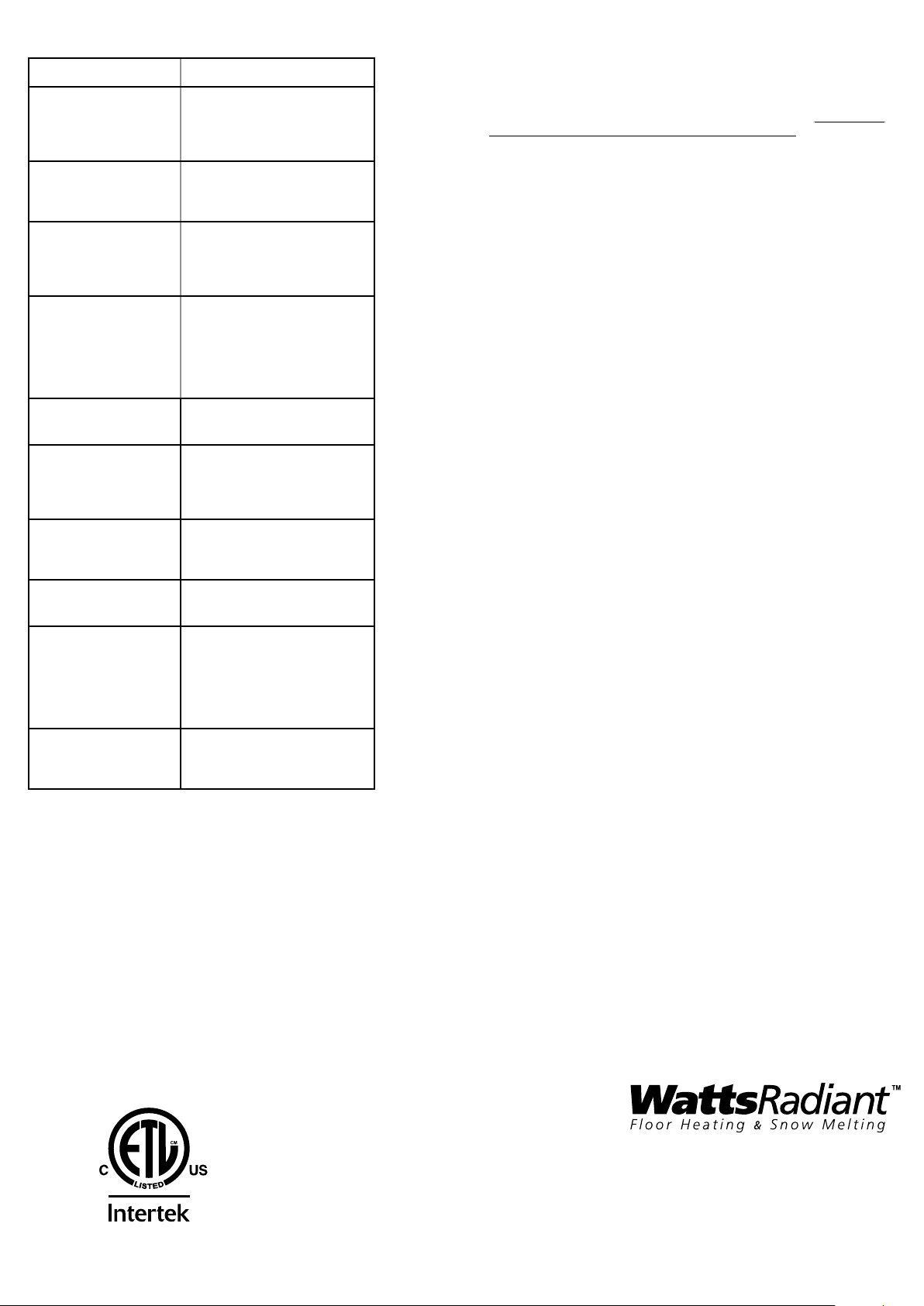
Troubleshoong
Problem Soluon
1. Check wiring connecons.
Thermostat works but no
heat from the system.
No display
GFCI is tripped
Heang occurs at the wrong
mes
Err1:Wrong oor sensor
Err2:Floor sensor shorted
Err3:Floor sensor missing
Err4/Err5:Internal sensor
fail
Err6:Internal temp limit
Err7:End-of-life
2. If GFCI is tripped, reset thermostat
with on/o switch.
3. Check resistances on oor heang
system. See manual for system.
1. Check wiring connecons.
2. Check circuit breaker or other
protecon “upstream” of
thermostat.
1. Check wiring connecons.
2. Reset thermostat by switching
on/o.
3. Check resistances on oor heang
system. See manual for system.
1. Check that the current me and
schedule mes are properly set to
AM or PM.
2. On uninsulated concrete
SmartStart may start heang very
early. You may turn this feature o
if not desired.
Floor sensor not correct type or
out of range. Check oor sensor
resistance.
Floor sensor short-circuited. Turn o
power at breaker. Make sure wires
are not crossed at the terminals.
Or replace sensor. Or Reset Factory
Defaults.
Floor sensor not aached and
thermostat is in oor sense mode.
Turn o power at breaker and aach
sensor. Or Reset Factory Defaults.
Internal air sensor is faulty. Replace
thermostat or operate in oor sense
mode.
Internal temperature overlimit. Make
sure sunlight is not directed at the
thermostat or other heat sources in
proximity. Make sure load does not
exceed 15 amps. Otherwise, turn
o power at breaker and contact
factory.
“End-of-life” indicaon. GFCI will no
longer funcon correctly or safely.
Reset the circuit breaker or replace
thermostat.
Limited Warranty
Was Radiant warrants this control (the product) to be free from defect in
material and workmanship for a period of (3) years from the date of original
purchase from authorized dealers. During this period, Was Radiant will replace
the product or refund the original cost of the product at Was Radiant’s opon,
without charge, if the product is proven defecve in normal use. Please return
the control to your distributor to begin the warranty process.
This limited warranty does not cover shipping costs. Nor does it cover a product
subjected to misuse or accidental damage. This warranty does not cover the cost
of installaon, diagnosis, removal or reinstallaon, or any material costs or loss
of use.
This limited warranty is in lieu of all other warranes, obligaons, or liabilies
expressed or implied by the company. In no event shall Was Radiant be
liable for consequenal or incidental damages resulng from installaon
of this product. Some states or provinces do not allow limitaons on how
long an implied warranty lasts, or the exclusion or limitaon of incidental or
consequenal damages, so the above exclusions or limitaons may not apply to
you. This warranty gives you specic legal rights and you may also have other
rights that vary from state to state.
Specicaons
Power Supply 120/240 VAC, 50/60 Hz
Maximum Load 15 amps, resisve
Maximum Power 1800 was at 120 VAC
3600 was at 240 VAC
GFCI Class A (5 milliamp trip nominal)
Display Range 32°F to 99°F (0°C to 37°C)
Seng Range 40°F to 99°F (4°C to 37°C)
Accuracy ± 0.9°F (0.5°C)
Environment Indoor dry locaon only
Storage Temperature 0°F to 120°F (-17°C to 49°C)
Floor Sensor Thermistor, 10k NTC type, double-insulated
Memory Programming retained indenitely
Current me/day will need reset if power is lost more than 30 minutes.
ETL Lisng Control No. 3037530
Conforms to UL 873, UL 943, CSA C22.2 No. 24, CSA/CAN C22.2 No. 144
A Watts Water Technologies Company
4500 E. Progress Place
Springfield, MO 65803
(417) 864-6108
(417) 864-8161 FAX
(800) 276-2419
wattsradiant.com
IOM-WR-SS-PRO2 1142
 Loading...