

Suntor ST30HPT User Manual

1st
ST30HPT User Manual
V2.0
TX on Board RX on Ground
Contents
I. Disclaimer...............................................................................................................................................................................2nd
II. Precautions for integration................................................................................................................................................... 2nd
III. List of in-box items................................................................................................................................................................3rd
IV. Interface Definition............................................................................................................................................................... 5th
1. TX Interface Definition...................................................................................................................................................5th
2. RX Interface Definition...................................................................................................................................................6th
V. Operating Instructions & Steps..............................................................................................................................................7th
VI. Antenna Installation............................................................................................................................................................. 9th
1. Multi-rotor UAV............................................................................................................................................................. 9th
2. Fixed Wing UAV..............................................................................................................................................................9th
VII. Software Operation........................................................................................................................................................... 10th
7.1. Two ways for changing the parameters................................................................................................................... 10th
7.2. How to use the software.......................................................................................................................................... 11th
7.2.1. Login...............................................................................................................................................................11th
7.2.2. RF Configuration............................................................................................................................................ 12th
7.2.3. RS1 Configuration.......................................................................................................................................... 14th
7.2.4. RS2 Configuration.......................................................................................................................................... 15th
7.2.5. IP New Network Configuration......................................................................................................................15th
7.2.6. RF New NET Configuration.................................................................................................................................... 16th
SUNTOR ELECTRONICS CO., LIMITED

2nd
I. Disclaimer
1) Be sure to use the parts provided by SUNTOR.
2) Reverse connecting power line positive and negative will burn the device out.
3) Before powering on please make sure the antenna are in good connection and not install or remove the
4) Given that the carbon fiber body and metal load may have shielding effects on antenna signals, they should not
5) Antennas on board should be kept away from other radio antennas to avoid electromagnetic noise and
6) If using PTZ Camera, please do the PTZ self-testing firstly then connect HDMI cable.
7) HDMI cable and antenna on board may interfere with GPS. Please keep the HDMI cable and antenna away from
8) Do not disassemble or modify SUNTOR ST30HPT. Any problem during installation, contact SUNTOR or SUNTOR
9) Keep appropriate distances between different electronic devices during installation to minimize the
10) Before using, please make sure all cables are in good connection and all components can work properly.
SUNTOR is the registered trademark of SUNTOR ELECTRONICS CO., LIMITED. All product names and brands in this
manual are trademarks or registered trademarks of the Company. SUNTOR ELECTRONICS CO., LIMITED reserves all
copyrights of the product and the manual. All the information must not be copied or reproduced in any form without
permission of SUNTOR. There may be semantic differences between disclaimers of different languages. The Chinese
version shall prevail in Chinese mainland, while the English version shall prevail in other regions. Thank you for
purchasing SUNTOR ST30HPT. Please use ST30HPT according to local radio regulations. Before using, please carefully
read this disclaimer. Once the product is used, all the contents of the disclaimer will be regarded recognized and
accepted. Please install and operate the product in strictly accordance with the requirements of this manual.
SUNTOR ELECTRONICS CO., LIMITED and its affiliates will not assume any legal responsibility for results or losses
caused by improper use, installation, assembly and modification (including the use of non-specified SUNTOR parts
and accessories, such as the radio power amplifier, antenna and SMA extension cord).
II. Precautions for integration
antennas with power on.
be installed between the antenna and ground terminal. Keep the antenna on board free from winding or
blocking by obstacles. The antenna end should be vertically downward without bending to prevent shortening
communication distance and failure communication.
interference. We recommend to make full use of data and video transmitting function of ST30HPT to minimize
the radio devices quantity on board.
the GPS module and its cables.
local branch office.
electromagnetic interference.
3rd
11) After starting the product, the self-test indicators of ST30HPT will continuously blink for 30s and then keep
bright. Only after the video from the camera shown on the display, then you can confirm that the device work
12) Check the surrounding environment to ensure there is no other 2.4GHz devices to cause interference.
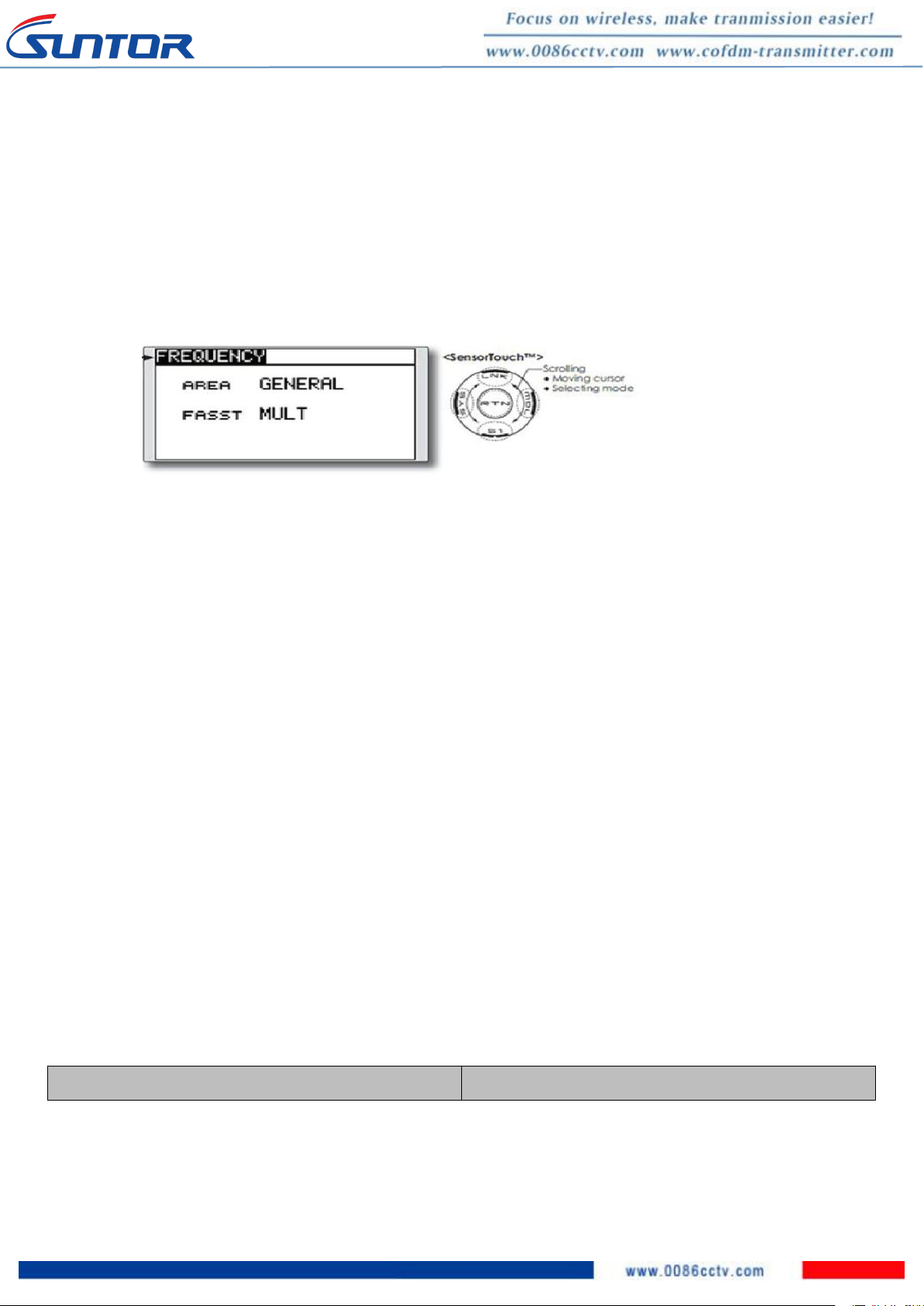
13) If you use the Futaba remote controller, the controller should be adjusted into the French mode. Otherwise, the
14) Adjust the Futaba controller into French mode as following steps:
15) [LINKAGE MENU]→FRQUENCY→ RTN b→ [AREA]→[FRANCE]
16) Before using, please check the power of RX and TX. If the receiver power off, transmitter on board will lose
17) Adjusting RX antenna inclination can improve the signal strength and image quality.
18) The camera should be fully charged to ensure normal video output.
19) ST30HPT support video and duplex data communication. If the video stuck or stopped for more than 10s. It
20) Please use good electromagnetic shielding accessories(HDMI Cable, HD display and so on)
On board x1
Ground terminal x1
properly now.
video transmission performance will be serious affected
Or connect ST30HPT S1 serial port with trainer interface on back side of Futaba by TTL cable. And set the Futaba RF
as OFF. Through the S1 port uplink the PPM/SBUS signal.
connection.
means the radio signal is weakened or the radio channel is narrowed. In this case, the aircraft need to fly back
to short the distance between TX and RX. Otherwise, the TX will lose connection.
Notes: Improper operation of ST30HPT may cause personal injury or damage to properties. Please pay high attention
to operation safety.
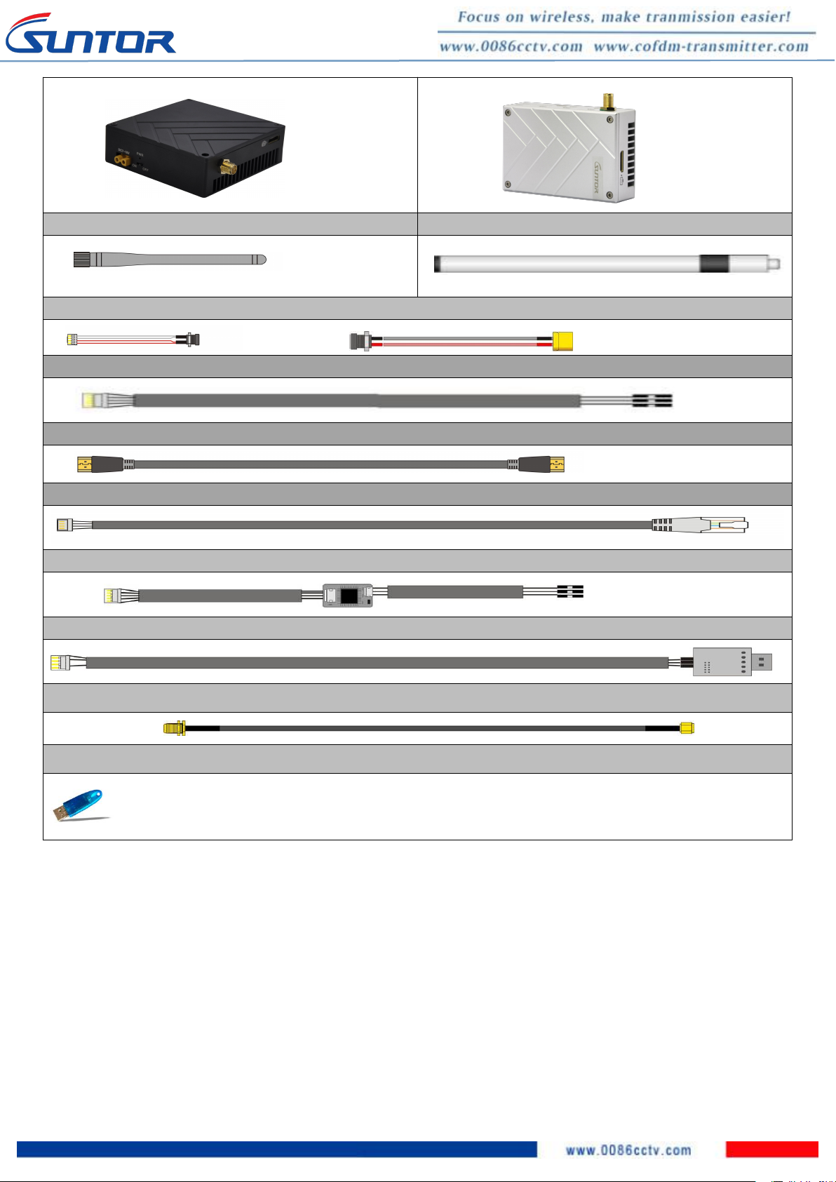
III. List of in-box items
4th
On board antenna x1
Ground antenna x1
DC power cable x2
TTL cable *2
HDMI video cable x2
Network cable x1
TTL to RS232 cable x2(Optional)
USB TTL serial port x1
SMA Cable(Copper wire tinned shield semi-soft line) x2
TPalyer Key
USB 2.0 Key
5th
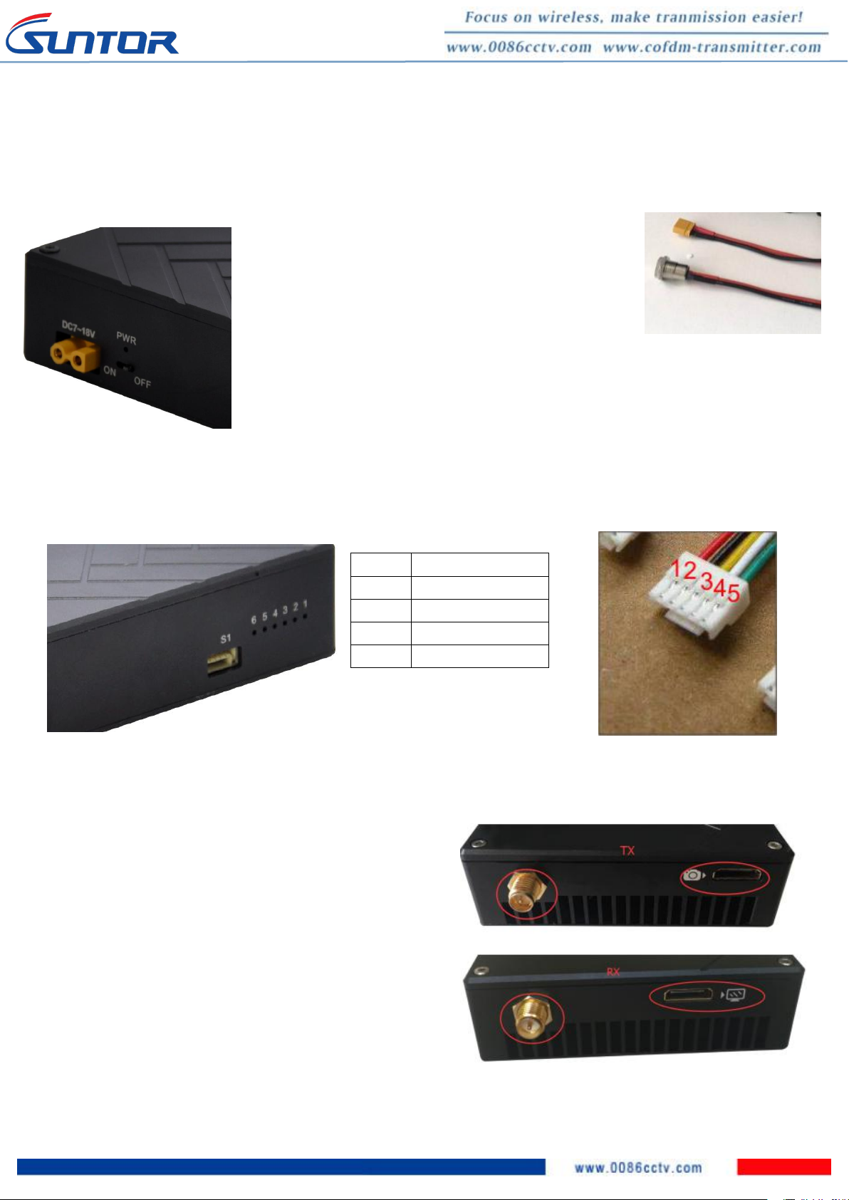
IV. Interface Definition
Power on/off: Pull - type switch
Power Connector: XT30PW-F(Female)
Power Cable: One end XT30PW(Male), the other end
DC(female)
1.3. RF and HDMI Interface
RF: Standard SMA to connect with antenna or feeder cable
HDMI Interface: Mini HDMI
(Port with camera Marker is video input, Port with display
marker is video output)
GH 5P
Signal Definition
1
TXD
2
RXD
3
3.3V
4
GND
1. TX Interface Definition
1.1. Power Interface
1.2. S1 Serial Port: 5P GH with lock socket(GH 1.25mm, we only use 4P)
 Loading...