

Page 1
5
Portable
Conductivity/
Resistivity
Meter
SC-110
Operation
Manual
Page 2

i
Content Table
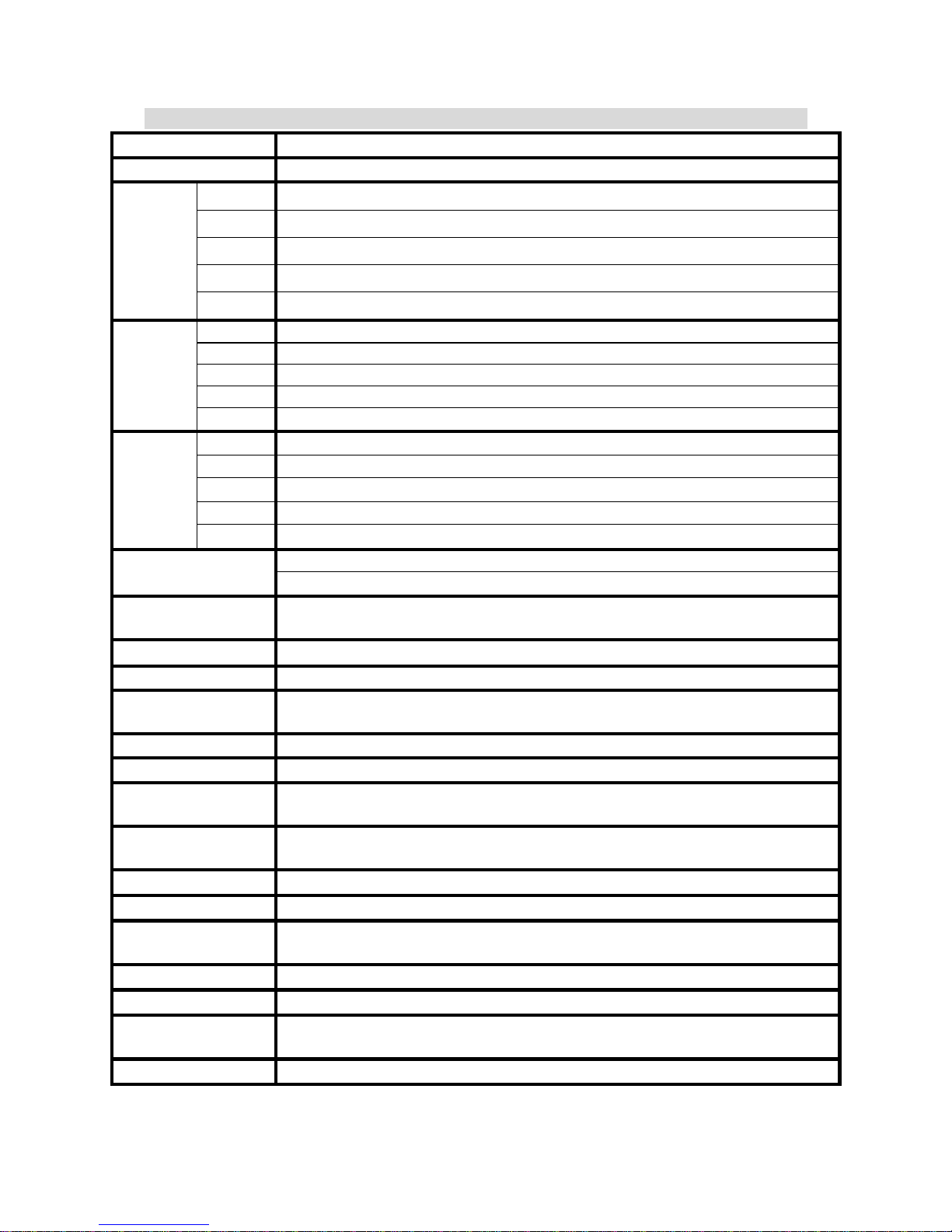
1. Specifications 1
2. Configuration
2.1 Display 2
2.2 Socket 2
2.3 Keypad 3
3. Operation
3.1 Measurement 4
3.2 Measurement function and file bit shift 4
3.3 Temperature function and compensation 5
3.4 Auto Read 5
4. Settings
Block diagram of settings 6
4.1 Parameter settings 7
4.1.1 Entry of set-up mode 7
4.1.2 Settings of measurement mode 7
4.1.3 Settings of data deletion 7
4.1.4 Settings of baud rate (BAUD) 8
4.1.5 Settings of system time 9
4.2 Deletion of all stored data 10
4.3 System reset 10
Block diagram of calibration and temperature compensation settings 11
4.4 Settings of calibration parameter 12
4.4.1 Electrode coefficient and calibration parameter 12
4.4.2 Standard solution calibration parameter 13
4.4.3 Temperature compensation coefficient 13
Block diagram of operations in measurement mode 14
4.5 Auto/manual data storage 15
4.5.1 Auto storage 15
4.5.2 Manual storage 15
4.5.3 Data full 15
4.6 Data readout and output 16
4.6.1 Auto transmission 16
4.6.2 Manual readout and transmission 16
5. Calibration
Block diagram of Calibration 20
5.1 Standard solution preparation 21
Page 3

ii
5.2 Calibration mode 21
5.3 Entry of calibration mode 21
5.3.1 Electrode coefficient calibration 21
5.3.2 Standard solution single-point calibration 21
5.3.3 Standard solution five-point calibration 22
6. Instruction set for RS232 23
7. Alternative fittings 23
8. Failure recovery 24
9. Maintenance 25
Page 4
1
1. Specifications
Mode SC-110
Function
µS/mS/MΩ/Salinity/TDS/Temp.
Cond.
0.00 uS/cm ~ 200.0 mS/cm in 5 measuring ranges for manual or auto switch
Res.
0.00~100.00 MΩ- cm
Salt
0.0~70.0ppt
TDS
0~2000ppm
Range
TEMP
-10.0~110.0°C
Cond.
0.01µS/cm
Res.
0.01 MΩ-cm
Salt
0.1 ppt
TDS
1 ppm
Resolution
TEMP
0.1°C
Cond.
±0.5%(±1Digit)
Res.
±1%(±1Digit)
Salt.
±0.5%(±1Digit)
TDS
±0.5%(±1Digit)
Accuracy
Temp.
±0.2°C(±1Digit)
PT-1000 or NTC 30K auto recognition
Temperature
Compensation
Auto / Manual selectable
Temperature
Coefficient
Non-linear / 0.00 ~ 10.00 % Linear
Ref. Temperature
T
ref
25℃
Manual calibration
Single point known standard solution or electrode constant calibration
Standard solution
calibration
Single or up to 5-point known standard solution calibration; default five
standard solution 10/84/1413 uS/cm & 12.88/100 mS/cm adjustable
RS232 interface
YES
Output Data logging
450 sets (measuring value, temp., date, time & ID)
Ambient
temperature
0~50°C
Storage
Temperature
-20~70°C
Display
1/2” LCD
Power
4 x AA battery
Battery
Around 350 — 1000 hrs according to measuring range; auto shut-off within10
minutes of no use
Protection Type
IP65
Certified to
CE
Dimension
(L x W x H)
185 x 98 x 38mm
Weight
0.35Kg
Page 5
2
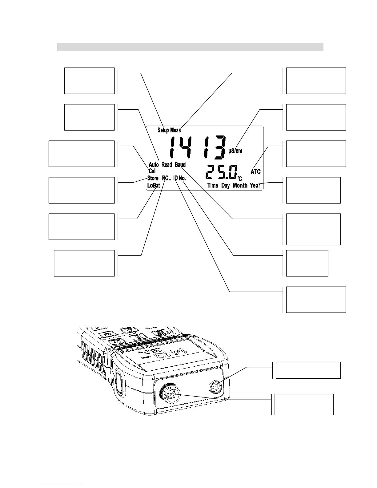
2. Configuration
2.1 Display:
2.2 Socket:
Set-up mode
Measurement mode
Measurement unit
Auto temperature
compensation
Time reminder
Auto read
Calibration mode
Data storage mode
Low battery
reminder
Data read
/Transmission mode
Data Storage ID
number
Storage ID
Transmission
speed
Conductivity
electrode socket
RS232 interface socket
Page 6
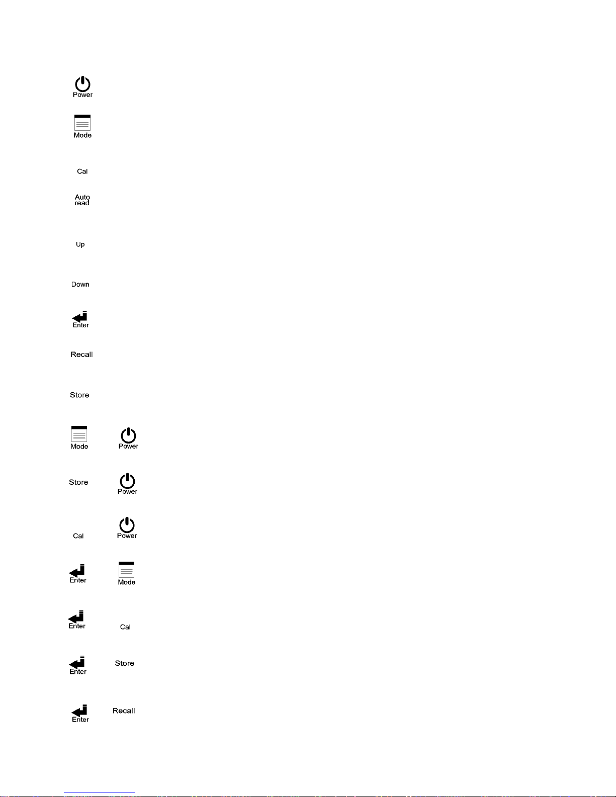
3
: Power switch. Push it to power on and push it again to power off. Auto shut-off
within10 minutes of no use
: Cond./Res./Salt/TDS measurement shift key; pushing it at any time will allow
backing to the measurement mode.
: Enter calibration mode.
: Key for auto read in measurement mode. Push one time for startup and push again for
cancellation.
: Upward or leftward key. For value adjustment, push it to increase the speed.
: Downward or rightward key. For value adjustment, push it to decrease the speed.
: (ENTER) Input, confirm, execute, and RS-232 manual output
: (Recall) Manual data read startup key and value read selection key.
: (Store) Manual data storage startup key
: Enter system parameter set-up, see 4.1
: Delete all stored data, see 4.2
: System reset, see 4.3
: Shift among the five manual modes and the auto mode. See 3.1
: Enter calibration parameter settings. See 4.4
: Enter auto continual storage settings. See 4.5
: Enter auto continual transmission settings. See 4.6
2.3 Keypad:
+
+
+
+
+
+
+
Page 7
4
3. Operation
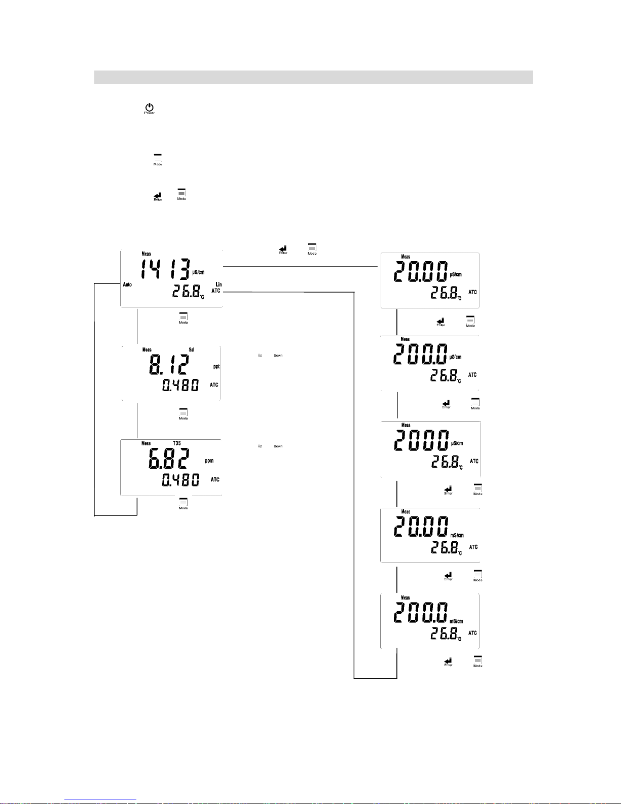
3.1 Measurement:
Push key to start up the instrument. It will automatically enter the measurement mode
of final operation and begin to measure.
3.2 Measurement function and file bit shift:
1. Push key to shift among Cond., Salt, and TDS in Cond. Mode. This function is
unavailable in Res. mode.
2. Push + keys to shift among the five manual shifts and the auto shift. After
entering auto mode, AUTO characters will disappear after 3 seconds.
Remark: Before measuring salt and TDS, please finish the calibration according to the
conductivity calibration steps, and then set the factor value according to the standard
solution of salt and TDS.
Push to shift
Salt unit
Push to shift
TDS unit
Push to adjust
the salt value. Note:
Factor range is 0.4~1.5
Push to adjust
Total Dissolved
Solids. Note: Factor
range is 0.4~1.5
Push +
Push +
Push
Push +
Push +
Push +
Push +
Page 8

5
3.3 Temperature function and compensation:
1. ATC: Auto judgment of whether there is temperature probe and recognition of NTC30K
or PT1000. Push or to adjust the temperature within in ±5℃. At the same time,
push keys to back to the original value.
2. MTC: Enter MTC 25℃ automatically when there is no temperature probe. Push
or to adjust the temperature. At the same time, push keys to back to the
default value 25.0℃.
3. Temperature compensation: Because the temperature of the to-be-tested solution may not
be 25℃, for standardization, the conductivity value of solution not at the temperature of
25℃ will be calculated to that of solution at the temperature of 25℃. This is temperature
compensation.
4. According to the temperature coefficient required by the measurement, three kinds of
temperature compensation can be applied: Lin, nLin, and non compensation (0.00%). See
the setting method in 4.4.3, and the user can set as needed.
5. Temp. Coefficient (called as TC for short), the conductivity value of the solution will
increase as the temperature rises at a different rate. See the relations as follows:
C25
Conductivity at 25℃
Ct
Conductivity at T℃
Formula 1: Ct = C25 { 1+β( T – 25 ) }
T Temp. of the tested solution
β Temp. Coefficient
Formula 2: β = ( Ct-C
25
) / { C
25
( T-25 )}
6. How to measure the TC of the tested solution: If the user wants to get a more accurate
value, the above formula can be applied to measure the TC of the tested solution and set
an appropriate TC on the machine. Take 0.01N Kcl as an instance, set the TC as non
compensation (0.00%) in the machine. Control the same tested solution respectively at
5℃ and 20℃. The value 1413μS tested at C25 is just the conductivity of the solution at
25℃; and the value 1278μS tested at Ct is just the conductivity of the solution at 20℃.
According to formula 2, β=1.91%.
3.4 Auto Read:
In the measurement mode, push to start up and push to read. Then, push
Enter to make the next measurement. Push or at any time will allow backing to
the measurement mode.
Auto Read symbol twinkles
for about 10 seconds.
Auto Read symbol stop twinkling
and a value will appear after the
measurement is stable.
Back to the measurement
Push or
Page 9
6
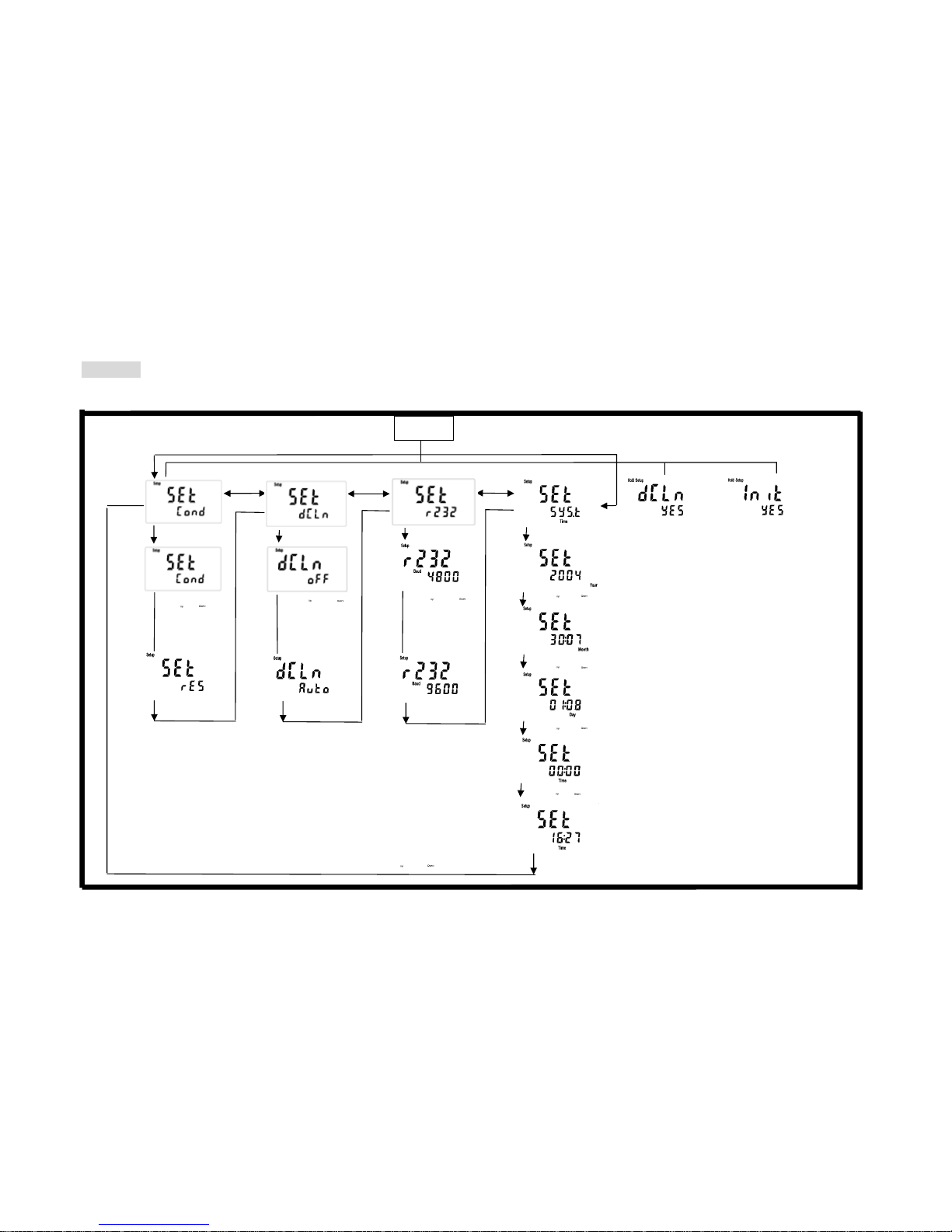
4. Settings
Block diagram of settings
↓: Enter key
→: Downward key for right
←: Upward key for left
Data overcast settings
Baud rate settings
Push or
to select auto
overcast or
cancel overcast
Push or
to select other
transmission
speed: 1200,
2400, 4800 or
9600
Push Store+Powe
r
,
Loose Power+Store
To delete all stored
data
Push CAL+Power,
Loose Power+CAL
System reset
Push Mode+Power
Loose Power+MODE to
enter the measurement
mode
Settings of measurement
Power off
System time settings
Push or to modify the minute
Push or to modify the year
Push or to modify the month
Push or to modify the day
Push or to modify the
Push or
to select
conductivity or
specific resistivity
Page 10

7
4.1 Parameter settings:
4.1.1 Entry of set-up mode:
In the power-off status, push first and then; after that loose first and
then to enter the parameter set-up mode. Use to select.
4.1.2 Settings of measurement mode:
4.1.3 Settings of data deletion:
Enter “Settings of data deletion”
Push or to select
MΩ-cm、uS/cm
Push to enter
Push to confirm
Push to enter
Enter “Settings of baud rate”
Push or to select auto
overcast or cancel auto overcast
Push to confirm
Page 11

8
4.1.4 Settings of baud rate (BAUD):
Enter “Settings of RS-232 baud rate”
Push to enter
Enter “Settings of system time
Push to confirm
Push or
to select
Push or
to select
Push or
to select
Page 12

9
4.1.5 Settings of system time:
Enter “Settings of system time”
Push to enter
Push or to modify the year,
push to confirm
Push or to modify the month,
push to confirm
Push or to modify the day,
push to confirm
Push or to modify the hour,
push to confirm
Push or to modify the minute,
push to confirm
Back to “Setting of measurement mod,
or push to back to measurement mode
Page 13

10
4.2 Deletion of all stored data:
In the power-on status, push first and then; after that loose first and then
to enter the data deletion mode.
4.3 System reset:
In the power-off status, push first and then; after that loose first and
then to enter the system reset page.
Factory defaults:
Data deletion settings: Auto
(BAUD) settings: 4800
Data transmission settings: read the stored data on the display (Sto diSP)
Back to the measurement
Back to the measurement
Push to confirm to delete all stored
data or push to back to the
Push to confirm the system reset;
or push to back to the
Page 14

11
Block diagram of calibration and temperature compensation settings
Settings in specific resistivity mode
Measurement mode
Power on
Calibration and temperature
compensation settings. Push Enter+CAL
Settings in conductivity mode
Measurem
Power on
Push Enter+CAL
Measurement temperature
Electrode coefficient
calibration settings
Standard solution
calibration settings
Measurement temperature
coefficient settings
Page 15

12
4.4 Settings of calibration parameter:
In the power-on status, push first and then to enter set-up mode of calibration
parameter. Use to select.
4.4.1 Electrode coefficient and calibration parameter:
(Only suitable when the measurement unit is conductivity)
Push to confirm
Back to measurement mode
Push to enter the settings
of calibration temperature
Push to confirm
Push or
to select
Push or to set the temperature
Push or
to select
Push to confirm
Page 16

13
4.4.2 Standard solution calibration parameter:
(Only suitable when the measurement unit is conductivity)
4.4.3 Temperature compensation coefficient:
Push or
to select
Push to confirm
Back to measurement mode
Push to confirm
Push to confirm
Back to measurement
Push to confirm
Push or
to select
Push or to set the temperature
Push or
to select
Push to confirm
Page 17

14
Block diagram of operations in measurement mode
Appear recently stored
Push or to close
Read the ID, and push or
to in
q
uire other data through ID
Back to the
measurement
mode
Read the stored yea
r
Read the stored date
Read the stored time
If the Auto and Store
icons shine, it means
that the data is stored
In case of data full
unable to store,
Store will twinkle
Back to the
measurement
Appear the
ori
g
inal ID
Push or to
set the ID number
Push or
to set the minute
If the Auto and Store
icons shine, it means
that the data is stored
Continual
measurement and data
Cancel continual
storage
Data store full
Transmissi
Power on
Storage
Auto store
Push Enter+Store
Appear the original ID
Back to the
measurement
Manual
store push
After
transmission,
back to the
measurement
mode
automatically
Auto transmission
Push Enter+Recall
Continual
The stored data
is transmitted
The stored data is
transmitted through RS232
The calibrated data is
transmitted to the dis
play
The stored data is
transmitted to the display
Manual read and transmission
Push Recall to shift circularl
y
among 4 modes
CEL
L
direct
Std simple point
calibration
Std five point
calibration
Back to
the
measurem
ent mode
Back to
the
measurem
ent mode
Back to
the
measurem
ent mode
After
transmission,
back to the
measurement
mode
automatically
Push or to
set the second
Push or to
set the ID number
Push or to
set the minute
Push or to
set the second
Push or to
modify the
Page 18

15
4.5 Auto/manual data storage:
4.5.1 Auto storage:
In the measurement mode, push first
and then to enter the auto continual
storage set-up mode.
4.5.2 Manual storage:
In the measurement mode, push to
enter manual store page.
4.5.3 Data full:
When the data is full to store, the
display will shine as a reminder, and
five seconds later, it will back to the
original measurement mode.
According to step 4.2, delete all the data.
In case of auto overcast, there will no
reminder of data full.
Back to the measurement
Push to confirm
Push or to set ID number;
Push to confirm the storage
Back to measurement mode
Push to confirm
Push or to set ID
number; Push to confirm
and enter settings of automatic
Push or to set the minute,
and push for confirmation and
settings of second
Push + or push to
cancel the auto store mode
If the Auto and Store
icons shine, it means
that the data is stored
Push or to set the seconds,
and push for confirmation. (The
minimum value is 5 seconds)
Page 19

16
4.6 Data readout and output:
4.6.1 Auto transmission:
In the measurement mode, push first
and then to enter auto transmission.
4.6.2 Manual readout and transmission:
In the measurement mode, push to shift
among 4 modes circularly, and push to
enter.
A. Read the stored data on the display
Push or to set the minute,
and push for confirmation and
enter the second setting.
Back to measurement mode
Push or to set the seconds,
and push for confirmation.
(The minimum value is 5 seconds)
If the Auto and Store icons
shine, it means that the data
is stored automatically
Push to enter, and the recently
stored data will appear
Push or to modify the
inquiry site. Push to confirm.
Read the ID and push and to inquire
other data according to the Id. Push to
read the data value and year.
Push to read the stored date
Push to read the stored time
Push + or push
to cancel the auto store mode
Back to measurement mode
Push
Push to read the store temperature
Page 20

17
B. Transmit the stored data through RS-232
Transmit all stored data through RS-232
C. Read the calibrated data on the display
C.1 Read the CELL calibrated data (when
the calibration parameter is set as
CELL calibration)
After the transmission, back
to measurement mode
Back to measurement mode
Push to enter, and the standard solution
value and electrode coefficient appear
Push to enter, the calibrated
temperature compensation coefficient
Push , and the calibration
record year appears
Push and the calibration record
date appears
Push
Push to transmit
Push and the calibration
record time appears
Page 21

18
C.2 Read simple-point calibration data of
standard solution (when the
calibration parameter is set as Std 1P
calibration).
Back to measurement mode
Push to enter, and the data and
electrode coefficient of standard
Push and the calibration record
Push and the calibration
record date appears
Push and the calibration record
time appears
Push
Page 22

19
C.3 Read five-point calibration data of
standard solution (when the
calibration parameter is set as Std 5P
calibration).
D. Transmit the stored data through RS-232
Transmit all stored data through RS-232
Back to measurement mode
Push , show the Buffer1. If
there’s no Buffer1, show NULL
Push , show the Buffer2. If
there’s no Buffer1, show NULL
Push , show the Buffer3. If
there’s no Buffer1, show NULL
Push , show the Buffer4. If there’s
no Buffer1, show NULL
Push , show the Buffer5. If
there’s no Buffer1, show NULL
Push and the calibration
record year appears
Push and the calibration
record date
Push and the calibration
Push
After the transmission, back
to measurement mode
Push to transmit
Page 23

20
5. Calibration
Block diagram of Calibration
Use ↑↓keys to
select
known
standard
solution value
Back to
measurem
ent mode
Push【MODE】
Use ↑↓keys to
select
known
standard
solution value
Back to
measurem
ent mode
按【MODE】
The
instrument is
reading
coefficient
The
instrument is
reading
coefficient
The
instrument is
reading
coefficient
Use ↑↓keys to
select
known
standard
solution value
The
instrument
is reading
coefficient
The instrument
is reading
coefficien
t
Use ↑↓keys to select
standard solution
value, including:
10.00uS/cm,
84.0uS/cm,
1413uS/cm,
12.88mS/cm,
100.0 mS/cm
five default values
Back to
measurement
mode
Use ↑↓keys to
select suitable
coefficient
C=.0100
C=0.100
C=0.475
C=10.00
Coefficient
valve shines,
use ↑↓ keys to
adjust
coefficient
value
Back to
measurement
mode
Push CALke
y
Power
Conductivity mode
Specific resistivity mode
Use ↑↓keys to
select
known
standard
solution value
The
instrument is
reading
coefficient
Backto
measu
r
Push【MODE】
Back to
measurem
Push【MODE】
Use ↑↓keys to select
known standard
solution value
Back to
measurem
ent mode
Push
Use ↑↓keys to
select suitable
coefficient
C=.0100
Coefficient valve
shines,use ↑↓
keys to adjust
coefficient value
to the known
standard solution
value
Back to
measurement
mode
Page 24

21
5.1 Standard solution preparation:
Put the agent potassium chloride in an oven of 150℃~180℃ for 5 hours, and then put it in a dry container
until it cools to the room temperature. Dissolve 0.7456 g potassium chloride into 1kilolitre pure water to be
0.01N potassium chloride standard solution (1413uS/cm).
5.2 Calibration mode:
Measured
functions
Calibration method Preset temperature compensation method
Set CELL CONSTANT
(Lin) 2.00% adjustable
Std 1P Prepare 5 selectable kinds of Buffer According to standard solution default
Conductivity
Std 5P Prepare 5 selectable kinds of Buffer According to standard solution default
Special resistivity Set CELL CONSTANT (nLin)
5.3 Entry of calibration mode: Temperature coefficient produces a great influence on measurement of
conductivity, so it is suggested to control the temperature of standard solution within 25±3℃ during the
calibration.
5.3.1 Electrode coefficient calibration:
1. When the calibration parameter is set as electrode coefficient set-up
mode (see 4.4), push to enter the electrode coefficient set-up page,
and then push to enter the next page.
2. Push or to select electrode coefficient default 10.00, 0.475,
0.100 or .0100 (special resistivity only includes 0.100 and .0100), in
order to select a suitable electrode coefficient value. After selecting the
suitable default, push to enter the next page.
3. Then, the electrode coefficient value begins to twinkle. Push or
to adjust the electrode coefficient value until equal to the buffer’s
standard. Then, push to back to the measurement mode.
5.3.2 Standard solution single-point calibration:
1. When the calibration parameter is set as single-point calibration
(see 4.4), push to enter Standard solution single-point calibration,
and then push to enter the calibration solution selection page.
2. Show the first known buffer’s standard and temperature. Push
or to adjust the known buffer’s standard, including five default
values 10.00uS, 84.0uS, 1413uS, 12.88mS and 100.0mS. After selecting
the suitable default, push to enter the next page.
3. The symbol Auto Read begins to twinkle, indicating that the
instrument begins auto calibration. After the calibration, the display
shows the calibrated electrode coefficient automatically.
Page 25

22
4. After the calibration, the display shows the calibrated electrode
coefficient automatically. Push to back to the measurement mode.
5.3.3 Standard solution five-point calibration:
1. When the calibration parameter is set as five-point calibration (see
4.4), push to enter Standard solution five-point calibration, and
then push to enter the first CAL1 page. Pushing at any time will
allow you intermit the calibration and back to the measurement mode.
2 Push or to select calibration point CAL1~5. Their default
values are respectively 10.00uS, 84.0uS, 1413uS, 12.88mS and
100.0mS. You can select any calibration point to make single-point,
two-point, three-point, four-point, and five-point calibration. After that,
clean and dry electrode before, and then put it into the buffer solution.
Push to enter the calibration page.
3. The symbol Auto Read begins to twinkle, indicating that the
instrument begins auto calibration. After the calibration, the display
shows the calibrated electrode coefficient automatically.
4. After the calibration, the display shows the calibrated electrode
coefficient automatically.
5. Push to enter the second calibration (CAL2) and finish the first
point calibration. Push to store the calibration data and the system will
exit calibration mode and back to measurement mode.
6. Other CAL2~CAL5 calibration applies the same steps as CAL1.
Characteristics: The design of this instrument has no limit of the calibration sequence, so after finishing
any point calibration, you can push to enter the next point calibration, and push to store the
calibration data. Then, exit the calibration mode and back to the measurement mode to finish the
calibration of any one or a few points.
5.3.4 Error messages: In case of any error messages when the calibration
fails, please refer to chapter 8 Failure Recovery to remove the errors and
restart the calibration.
Page 26

23
6. Instruction set for RS232
The communication between the base unit and the Windows Hyper Terminal is set as follows:
1. Click 【start】on the lower left, and select 【program set】→【Accessorial applications】→
【Communication】→【Hyper Terminal 】, and the display will show a window of “Hyper Term inal” .
2. Set icon and online name for Hyper Terminal before entering the “ONLINE” window.
3. Select communication terminal (for example, select 「connect COM1」) in 「Use online (N):」in
“ONLINE” window, and then enter the window “COM1 content”.
4. In 「transmission bit per second (B):」in “COM1 content”, select baud rate=9600 (It should be consistent
with controller settings), data bit (D)=8, parity check(P)=none, stop bit (S)= 1, flow control (E) =none.
5. Click 【intermit online】
6. Click 【file】→【content】, and enter the window “XXX content”.
7. Click 【setting value】→【ASCII setting】to enter “ASCII setting” window.
8. In “ASCII setting” window, select 「newline at the end of each line (S)」,「Respond to the input characters
(E)」,「Add LF at the end of each input line (A)」 and 「newline if exceeding the width of terminal (W)」,
and then leave “ASCII setting” window by pushing 【confirm】.
9. Push 【confirm】to leave “XXX content” window.
10. Push 【call】to link the communication.
7. Alternative fittings
Name Order number
Conductivity electrode C≒0.475
8-243
Special resistivity electrode C≒0.01
8-221-01
Special resistivity electrode C≒0.05
8-222-01
Flow cell 8-TF-02
10 µS KCl Calibration Solution in 16-oz(about 473ml) glass bottle
00652-24
84 µS KCl Calibration Solution in 500-ml leak-proof bottle
00653-16
1,413 µS KCl Calibration Solution in 500-ml leak-proof bottle
00653-18
12,880µS KCl Calibration Solution in 500-ml leak-proof bottle
00606-10
100,000S KCl Calibration Solution in 16-oz(about 473ml) glass bottle
00652-34
Page 27

24
8. Failure recovery
Failure phenomenon Possible causes Disposition
ERR1 The electrode coefficient bears a
large deviation when use the
standard solution in calibration.
Replace new standard solution for another
calibration. For others, please refer to the
disposition of measurement deviation in
the following.
ERR2 The measurement is unstable when
use the standard solution in
calibration.
Please refer to the disposition of unstable
measurement in the following.
The electrode is polluted. Clean and wash the electrode
The electrode coefficient (C) is
wrongly set.
Modify the electrode coefficient
The temperature coefficient (TC) is
wrongly set.
Modify the temperature compensation
coefficient.
The electrode is damaged or
broken-down.
Readjust the coefficient
There are air bubbles on the
electrode.
Churn up to remove the bubbles.
The battery is low. Replace with new battery.
Measurement deviation
Instrument fault Send to the original factory for repair.
The electrode is disturbed by the
bubbles.
Churn up to remove the bubbles.
The electrode is polluted. Clean and wash the electrode.
Electrode fault Replace the electrode.
The battery is low. Replace with new battery.
Unstable measurement
Instrument fault Send to the original factory for repair.
The electrode plugs is not inserted
into the required place.
Check the electrode plugs and reinsert it
into the required place.
The conductivity value is
zero or the special
resistivity value is out of
the range.
The electrode is broken. Replace the electrode.
Not soak deeply enough. Deepen the soaked length to ensure the
accuracy of temperature.
Deviation of standard comparison Use standard thermometer comparison to
correct the difference in temperature
The temperature sensor is broken Replace the electrode.
The battery is low. Replace with new battery.
Temperature deviation
Instrument fault Send to the original factory for repair.
The electrode plugs is not inserted
into the required place.
Check the electrode plugs and reinsert it
into the required place.
The temperature sensor is broken Replace the electrode.
Temperature is wrongly
displayed.
Instrument fault Send to the original factory for repair.
Page 28

25
9. Maintenance
9.1 Maintenance of base unit: Please keep it in dry and ventilated environment. Use wrung soft wet cloth to
wipe the generally polluted surface. For pollution by grease, please remove the stain with waxed soft wet
cloth. Solvent is strictly prohibited.
9.2 Battery replacement:
a. When the display shows Lo Bat during the instrument works, please replace with alkali dry cells.
b. First power off the instrument, and then use cross head screwdriver to dismantle the four screws on the
back of the instrument.
c. Open the back cover and remove the battery protection cover.
d. Take out the old battery and put in 4 new AA batteries in correct directions.
e. Reinstall the battery cover and back cover, and lock the 4 screws to finish the battery replacement.
f. Caution! The battery replacement should be finished within 20 seconds; otherwise the date data will
disappear and should be reset.
9.3 Maintenance of electrode: The substances on the measuring side of electrode will influence the
measurement value and cause deviation. Please clean and maintain it regularly. Use soft brush or cotton stick
to clean the graphite surface of electrode.
Pollution types Cleaning methods
Pollution by grease Use mild degreasing agent to clean the electrode.
Pollution by dirt Soak in 2~5% Hcl for about 5 minutes.
 Loading...