

Page 1
1
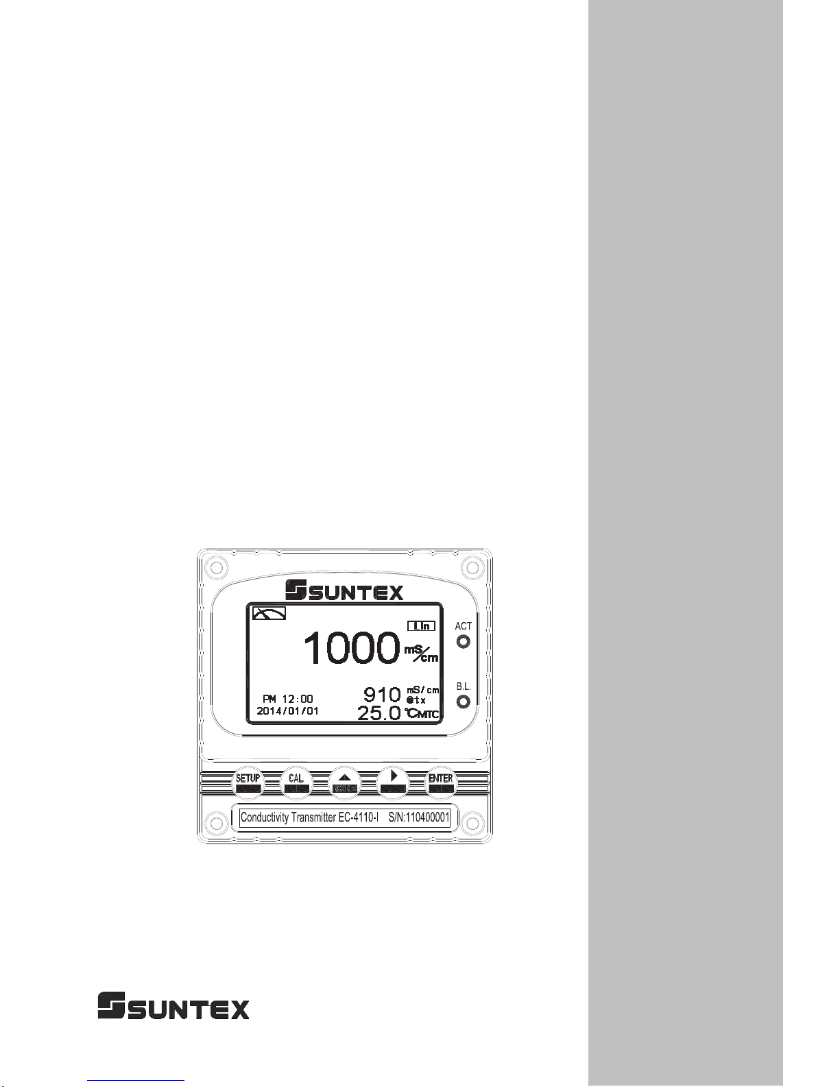
EC-4110-I
EC-4110-ICON
ġ
Intelligent
ġ ġ
Conductivity
Transmitter
Operation
Manual
Page 2

Precautions for installation
Brief Instruction
1
1. Specifications
1.1 Specifications
4
1.2 Product packing 5
1.3 Measurement principle
6
2. Assembly and installation
2.1 Transmitter installation 8
2.2 Illustration of panel mounting 8
2.3 Illustration of wall mounting and pipe mounting
9
3. Overview of Conductivity Transmitter EC-4110-I/EC-4110-ICON
3.1 Illustration of rear panel 10
3.2 Illustration of terminal function
10
3.3 Description of terminal function 11
3.4 Wiring of cable 12
3.5 Circuit of cable
12
3.6 Illustration of electrical connection 13
3.7 Wiring diagram of extension cable
14
4. Configuration
4.1 Illustration of front panel
15
4.2 Keypad 15
4.3 LED indicators 15
5. Operation
5.1 Measurement mode
16
5.2 Set-up menu 16
5.3 Calibration menu
16
5.4 Shortcuts 16
5.5 Default value
5.5.1 Setting default value 16
5.5.2 Calibration default value
17
6. Measurement display mode
6.1 T ext mode
18
6.2 Real-time chart mode
19
6.3 Trace mode
20
6.4 Warning symbols and text
21
CONTENTS
Page 3

7. Settings
Block diagram of settings
22
7.1 Entry of set-up menu 24
7.2 Security code of settings(Code)
25
7.3 Language 26
7.4 Measurement parameters(Mode) 27
7.4.1 Conductivity with temperature compensation 27
7.4.2 Absolute conductivity
29
7.4.3 Concentration 31
7.4.3.1 Defined concentration table
33
7.4.4 TDS 37
7.4.5 Salinity
38
7.5 Product adjustment 39
7.6 Temperature 40
7.7 Temperature compensation coefficient
41
7.8 Relay 1 43
7.9 Relay 2 44
7.10 Clean
45
7.11 Current output 46
7.12 RS-485 communication 48
7.13 Date/Time (Clock)
49
7.14 Sample average of measurements (Digital filter)
50
7.15 Backlight 51
7.16 Contrast
52
7.17 Logbook 53
7.18 Automatically back to measurement mode(Return) 54
8. Calibration
Block diagram of Calibration
55
8.1 Entry of calibration menu 56
8.2 Security password of calibration
57
8.3 Zero-point calibration
58
8.4 Cell constant calibration
59
8.5 Standard solution calibration(Std. solution)
60
8.5.1 KCl standard solution 60
8.5.1 NaCl standard solution
62
8.6 Automatically back to measurement mode(Return) 64
Page 4

Thank you for purchasing Suntex products. In order to continually improve and enhance the transmitter’s
function, Suntex reserves the right to modify the content and icon display of the product. The actual situation
is subject to the instrument without notice. The operation manual is only provided for function and
installation description, Suntex Instruments Co., Ltd. is not liable for any person or entity for any direct or
indirect loss or damage due to improper usage of this product. If you have any questions or find omission,
negligence or mistakes of the operation manual, please contact with our staff, thank you.
Precautions for installation
Wrong wiring will lead to breakdown or electrical shock of the instrument, please read this
operation manual clearly before installation.
zMake sure to remove AC power from the transmitter before wiring input, output connections,
and remove it before opening the transmitter’s housing.
zThe installation site of the transmitter should be good in ventilation and avoid direct
sunshine.
zThe material of signal cable should be special coaxial cable. Strongly recommend using our
coaxial cable. Do not use normal wires instead.
zAvoid electrical surge when using power. Especially when using three-phase power, use
ground wire correctly. If the power surges interference occurs, separate the power supply of
transmitter from the control device, such as: dosing machines, mixers, etc. to make individual
power supply for the transmitter; or set surge absorber to reduce the power surges at all
electromagnetic switches and power control device coils.
zThe internal relay contact of the instruments is for alarm or control function. Due to safety,
please must connect to external relays which can stand enough ampere to make sure the
safety operation of the instrument.˄Please refer to chapter 3.6ȾIllustration of electrical
connectionȿ˅
zThere a manufacturer logo usually shows in the display of transmitter, and the illustration of
each function in the manual is no longer expressed.
!
!
!
!
!
!
!
!
!
!
!
Page 5

9. Modbus protocol and instructions 65
9.1 Communication connection
65
9.2 Modbus address table 67
9.3 Modbus example descriptions
71
10. Error messages (Error code)
72
11. Installation of cells
11.1 Appearance of cells
73
11.2 Installation approach
74
11.2.1 Flange installation 74
11.2.2 Tee installation
75
11.2.3 Immersion installation 76
12. Appendix
77
Page 6
Brief Instruction
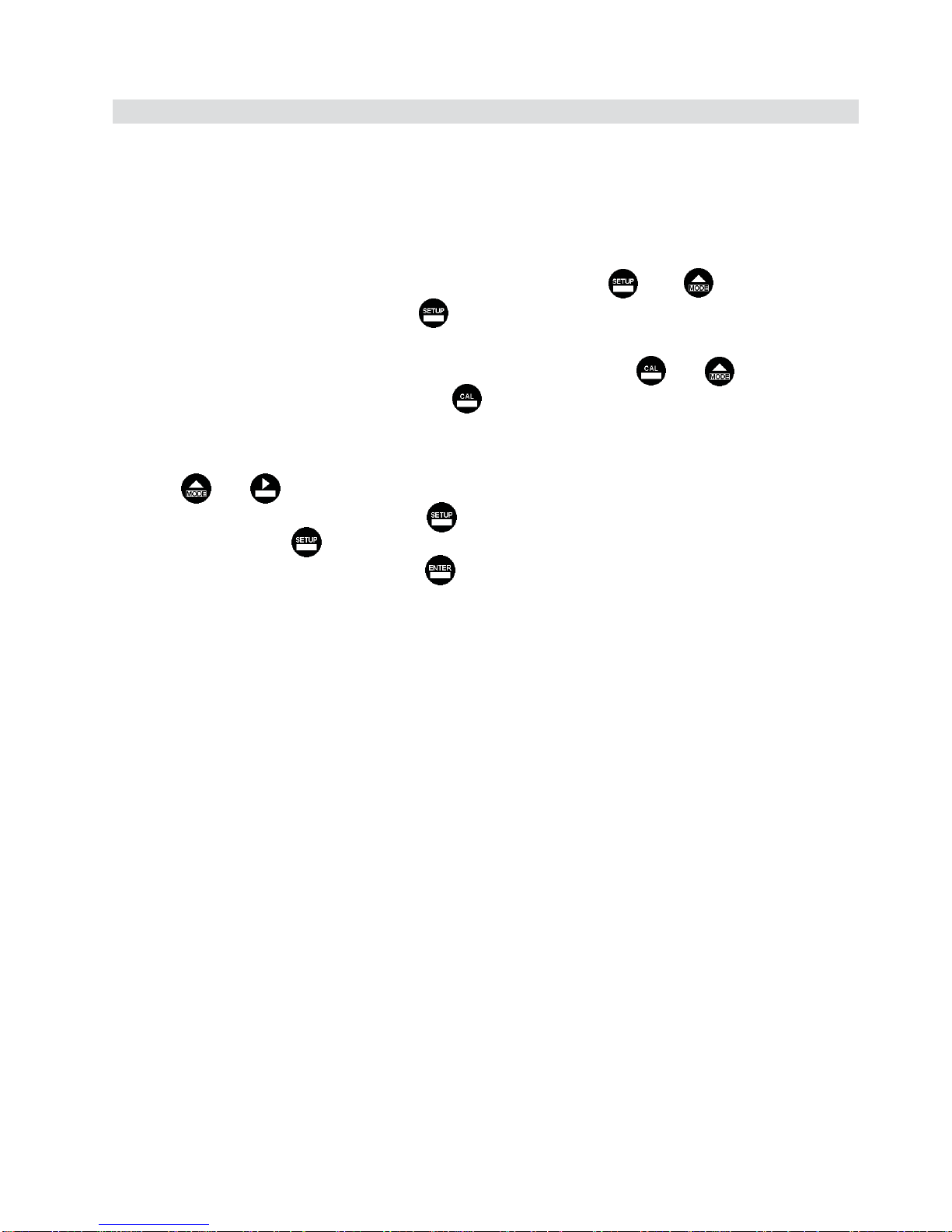
Description of set-up settings (see chapter 7 for details)
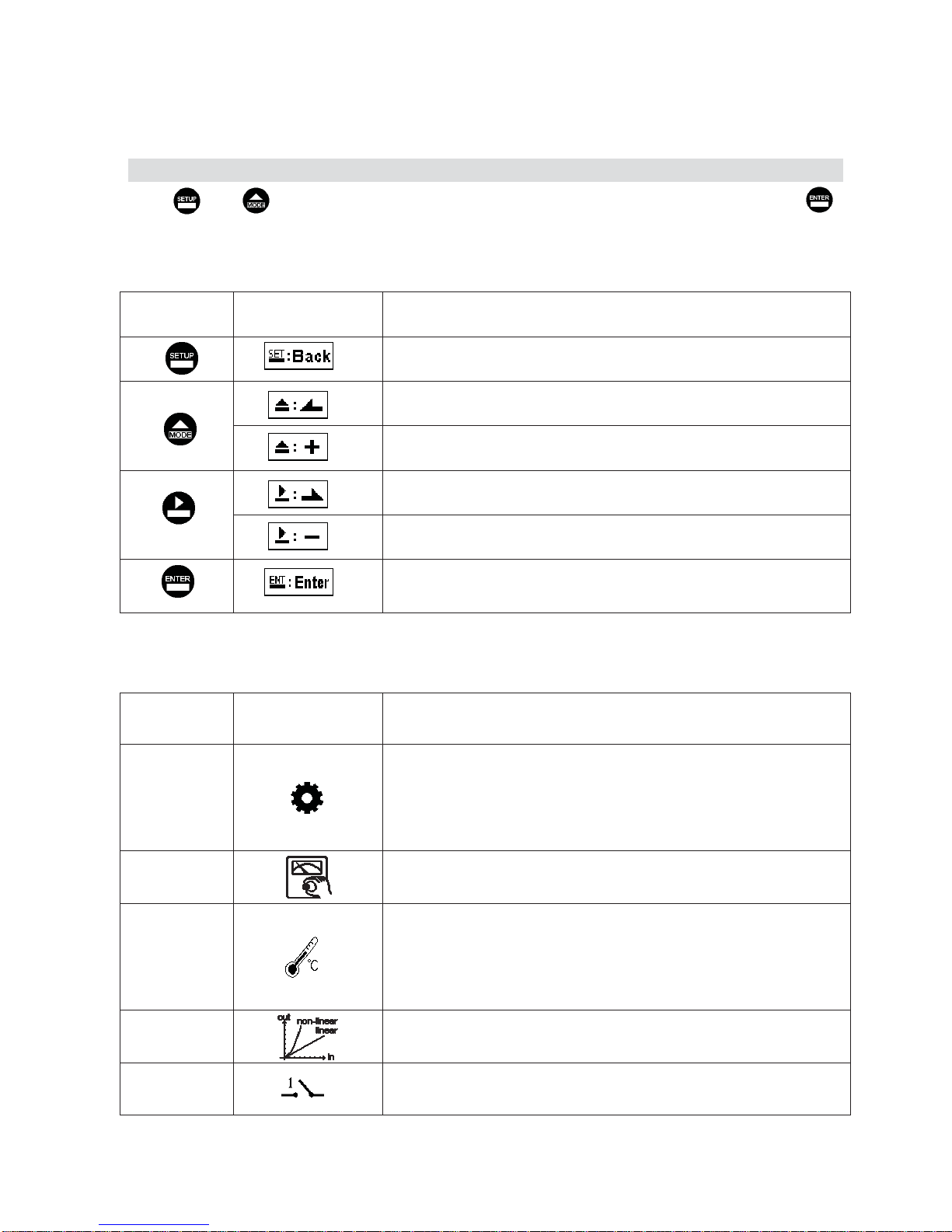
Press and simultaneously to see the overview of the set-up settings now. Then press I
if you would like to modify set-up settings. Press keypad according to index of keypad on the screen.
Index of keypad
keypad Accordingly item Description
Back to upper layer
Choose leftward of change to left page
Increase digit
Choose rightward of change to right page
Decrease digit
Confirm settings after modifications and then go through next
step
Selection of set-up items
keypad Accordingly item Description
Mode
Measurement mode, to choose Conductivity with temp.
compensation (Cond.@tref), Concentration, TDS, Salinity or
Absolute Conductivity (Cond.@tx) and measurement mode can
be displayed in Text Mode, Real-time Mode, or Trace Mode.
Product Adj. Sample reading adjustment—for resistivity mode only.
Temperature
Temperature measurement and compensation, including MTC,
PTC1000, PTC100, or NTC (4 types in total). MTC---Manual
Temperature Compensation, PTC1000/PTC100/NTC--- Auto
Temperature Compensation
Compensation
Temperature compensation setting, selection from linear(Lin.),
non-linear(Non-Lin.), no compensation(Lin., 0.0%), 3 types
Relay 1 First relay setting, to choose action off or Hi/Lo alarm
к
Page 7
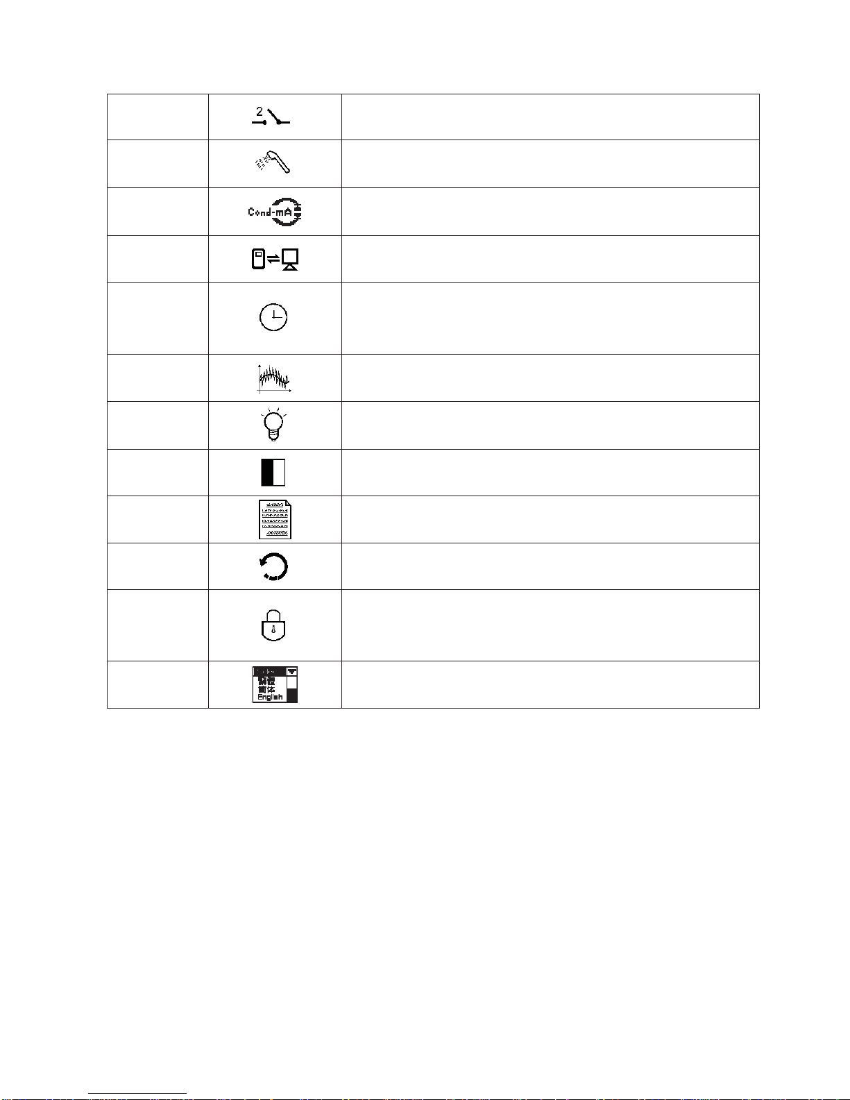
Relay 2 Second relay setting, to choose action off or Hi/Lo alarm
Clean
Automatic wash time setting, to choose electrode clean
equipment’s ON and OFF duration
Current
Output
Current output according to Cond.@tref, Concentration, TDS,
Salinity, or Cond.@tx setting range
RS-485 RS485 serial interface (Modbus protocol)
Clock
Clock setting (When out of power and reboot it, the
instrument’s time setting can maintain to the real time. If
not, please replace the inner 3V CR2025 battery.)
Digital Filter
Take every serial 1~60 measurements, average them
continuously, and make it as the readings
Back Light
Backlight setting, to set Auto/ON/OFF backlight, brightness,
and sensitivity
Contrast Contrast of screen setting
Logbook Event recorder logbook (50 data)
Return Setting of returning to the measurement mode
Code
Security code of set-up mode. The set-up code is precedential to
calibration code, thus it can pass a different security code of
calibration.
Language Available for English, Traditional Chinese, Simplified Chinese
л
Page 8
Description of calibration settings (see chapter 8 for details)ġ ġġġġġġġġġġġġġ
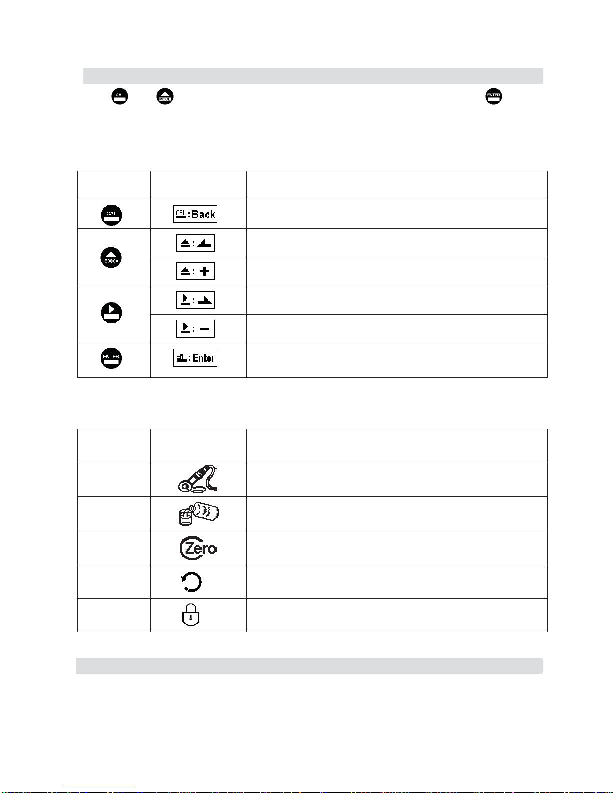
Press and simultaneously to see the last calibration information. Then press if you
would like to make a new calibration or modify setting of calibration. Press keypad according to
index of keypad on the screen.
Index of keypad:
keypad Accordingly item Description
Back to upper layer
Choose leftward of change to left page
Increase digit
Choose rightward of change to right page
Decrease digit
Confirm settings after modifications and then go through next
step
Selection of calibration items
keypad Accordingly item Description
Cell Constant
To adjust the instrument cell constant setting until the value
goes the same with the given cell constant of the sensor
Std. Solution Use the appropriate standard solution to calibrate the system
Zero Zero-point calibration
Return Time interval setting of returning to the measurement mode
Code Security code of calibration mode.
Note
ġ
Due to the need for continuous improvement of the transmitter function, we reserve the right to modify the
content and the icon of the function. The actual icons and contents are subject to the instrument without notice.
м
Page 9

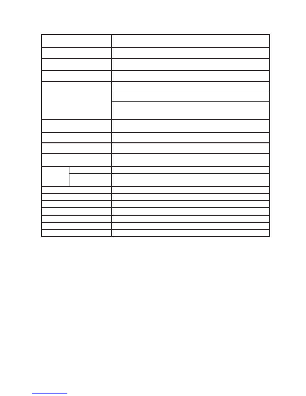
1. Specifications
1.1 Specifications
Model EC-4110-I EC-4110-ICON
Measuring modes Conductivity/TDS/Salinity/Temp./Concentration (EC-4110-ICON only)
Ranges
Conductivity
0.000 ȝS/cm~2000 mS/cm, Auto or Fixed
Salinity
0.0 ppt~70.0ppt
TDS 0ppm~19999ppm; 0.00~199.9ppt
Temp. PTC1000/PTC100: -30.0~200.0ÛC, NTC30K: -30.0~130.0ÛC
Concentration
NaCl_28%烉0-28 %
HCl_18%烉0-18 %
HCl_39%烉22-39 %
HNO3_30%烉0-30 %
HNO3_96%烉35-96 %
NaOH_24%烉0-24 %
NaOH_50%烉15-50 %
H2SO4_37%烉0-37 %
H2SO4_88%烉28-88 %
H2SO4_99%烉89-99 %
H3PO4_35%烉0-35 %
The boundary value of conc.
conversion range of each solution can
vary with changes of temp., if go over
range, there twinkles an alarm on the
display screen.
Self-defined table (up to 9 temp. data,
and there are 9 corresponding points
for cond. v.s. conc. at each temp.)(9 x
9 matrix)
Resolutions
Concentration
0.01 %
Conductivity
0.1 ȝS/cm, 0.01 / 0.1 / 1 mS/cm
Temp. 0.1ÛC
Accuracy
Conductivity
±1% (± 1Digit)
Temp.
±0.2qC (± 1 Digit),
Equipped with temperature error correction function
Temperature
Compensation
Automatic with NTC30K/ PTC1000/PTC100
Manual T emperature Compensation
Calibration mode
(1)Manual cell constant adjustment
(2)Conductivity standard solution calibration
(3)Zero-point calibration
Product Adjustment 0.7000~1.3000
Ambient Temp. 0~50 ÛC
Storage Temp. -20~70 ÛC
Cell Constant freely selectable 0.008~9.9999 cm-1
н
Page 10
Temperature Coefficient
Linear temperature compensation from (0.00%~ 40.00%),
Non-Linear compensation, or No compensation
Compensation Temperature Freely set reference temperature 0~200 ÛC
Display Screen
Large LCM with sensitization sensor for auto/manual illumination
function and contract functio
n
Languages
English / Traditional Chinese / Simplified Chinese
Display
Text mode: Numerical display
Chart mode: 3 mins real-time dynamic graph
(
conc. and cond. only)
Trace mode: Set up from 3 mins to four weeks duration of the
measured value trend graph
(
conc. and cond. only)
Analog output
Isolated DC 0/4~20mA corresponding to main measurement,
max. load 500:
Logbook 50 event records
RS-485 interface Isolated (MODBUS RTU or ASCII)
Modbus communication
Offer measuring value, calibration data, product adjustment,
logbook, control parameter, etc or system setup
Settings
Contact RELAY contact, 240VAC 0.5A Max.(recommended)
Activate
Hi/Lo. Hi/Hi. Lo/Lo selectable two limited programmable,
ON/OFF
Wash RELAY contact ON 0~99min. 59sec. / OFF 0~999hr 59min.
Protection IP65 (NEMA 4X)
Power Supply 100V~240VAC±10%, 7W max., 50/60Hz
Installation Wall or Pipe or Panel Mounting
Dimensions 96m × 96mm × 132mm (HuWuD)
Cut off Dimensions 93 mm u 93 mm (HuW)
Weight 0.5Kg
Note: The specifications are subject to change without notice.
о
Page 11

1.2 Product packing
1.2.1 Standard accessories
1. Transmitter
2. 8-201-PFA-10 sensor assembly(Including temperature sensor with PTC1000 and signal cable
for 10 meter)
1.2.2 Optional accessories
If necessary, please order the spare parts as follows:
1. Installation炷please refer to ch.11: Installation of Sensor Assembly炸
1.1 Flange Mounting
1. 8-201-PFA-10 sensor assembly
2. 5419059 Teflon gasket
3. 5420048 FEP sealing loop
4. 5329003 G3/4" hexagon nut
1.2 Tee installation
1. 5419061 stell tee(2"-3/4")
2. 5329003 G3/4" hexagon nut
1.3 Immersion installation
1. 5419060 immerison nut fitting(1"-3/4")
2. 7202-DO100 DO protection holder 1M
3. Threading type烉8-26 waterproof cap or coiling type烉8-09-6 circle junction box
2. Extension cable max. up to 50M (zero-point calibration, cell constant calibration or product
adjustment are required after installation)
1. 8-09-9 square junction box 9T
2. 5251023 signal cable, please advise specific length as ordered(M)
3. Standard calibration buffers(optional)
Note: Installation can be referred to chap. 11: Installation of Sensor Assembly
1.3 Measurement principle
1. EC-4110-I/EC-4110-ICON utililze conversion of electric field and magnetic field to measure
the conductivity in a sample solution. Sensor assembly is composed of Drive Coil and
Receive Coil, whose induction is not directly contact with sample solution, belonging to
inductive type. It is also composed of chemical-resistant materials, for example: the
8-201-PFA-10 is made up of PFA that can be applied to acidic, alkaline, salt solutions,
effluents, etc. in online monitoring industrial environments.
2. EC-4110-I/EC-4110-ICON apply alternative signals of electric field to activate drive coil to
produce the magnetic field. After that, sample solution(containing ions in different conc.)
turns into a conductive circuit, and then the signal can b e received on receive cell, turned into
magnitude of current to measure the conductivity.
3. The temperature probes have three-wiring type PTC1000 and PTC100 and two-wiring type
NTC30K as reference. Users can select the spec according to sensor assembl y. ȾCond.@txȿ
which presents conductivity is being measured at actual tmeperature Ⱦtxȿ, is regarded as
absolute conductivity. Refer to temperature compensation modes (linear, non-linear, or off)
п
Page 12

and reference temperature, “Cond.@tref” is to present conductivity based on desired ref.
temperature.
4. EC-4110-I/EC-4110-ICON both have measurement of salinity and TDS.
5. EC-4110-ICON has built-in conc. conversion table including NaCl, HCl, HNO
3
, NaOH,
H
2SO4
, H3PO4, etc. Users can select the corresponding solution types and conc. range. When
the conc. range is not applicable, there twinkles error message as an alarm during
measurement. The absolute conductivity “Cond.@tx” can be turned into concentration of th e
sample solution, and with compensation of ref. temperature it also can be treated as
“Cond.@tref.”
6. EC-4110-ICON has self-defined conversion table between cond. and conc., and there are conc.
units %, ppm, or ppt as reference.
7. Self-defined table( max. up to 9 temperature data, and there includes 9 corresponding cond.
and conc. at each temp.) (9 x 9 matrix) can be input corresponding conductivity and
concentration at the same temperature by users. The temp., cond., and conc. can be
individually input in ascendant or descendant order. After that, the unit is going to check the
data and correct somewhere the order goes wr ong. When users only have data of cond. and
conc. at one kind of temp. for conversion, it is necessary to apply linear temperature
compensation to input T.C. value.
8. Due to conductivity attained by electromagnetic induction not by contact type, cell constant is
to perform the geometric structure characteristic of a drive coil and a receive coil, and the
signal cable of the sensor is labeled with cell constant made by lab when out of factory. The
inductive signals can be influenced by the surroundings environments such as installation
pipeline wall effect, metal(conductive) pipeline and plastic(insulation, non-conductive)
pipeline, the distance from sensor assembly and the shell of pipeline. After installed,
zero-point calibration in air and cell constant calibration are required, and there is no need to
change the labeled cell constant since it can use span calibration to make product adjustment
in the field directly.
9. It should restart zero-point calibration in air after each installation or maintenance, and the
surface of sensor assembly needs cleaning without any attachment, making it dry, and using
cell constant or product adjustment for calibration.
10. The default measuring range is 2000mS/cm, and users can select 2000mS, 999.9mS, 99.99mS,
9.99mS, ȝ6, or AUTO, where AUTO means automatic switch unit.
р
Page 13

2. Assembly and installation
2.1 T ransmitter installation:
This transmitter can be installed through panel mounting, wall mounting and 2” pipe mounting.
Installation of panel mounting:
Firstĭ prepare a square hole of 93 x 93mm on the panel box, and then insert the controller
directly into the panel box. Insert the accessorial mounting bracket from the rear, and make it be
fixed into pickup groove.
2.2 Illustration of panel mounting
93 mm
93 mm
Hole size
87 mm
為
87 mm
Hole distances on the panel box
Mounting bracket
Illustration of panel mounting,
fixed with mounting bracketġ
為
為
為
112 mm
с
Page 14
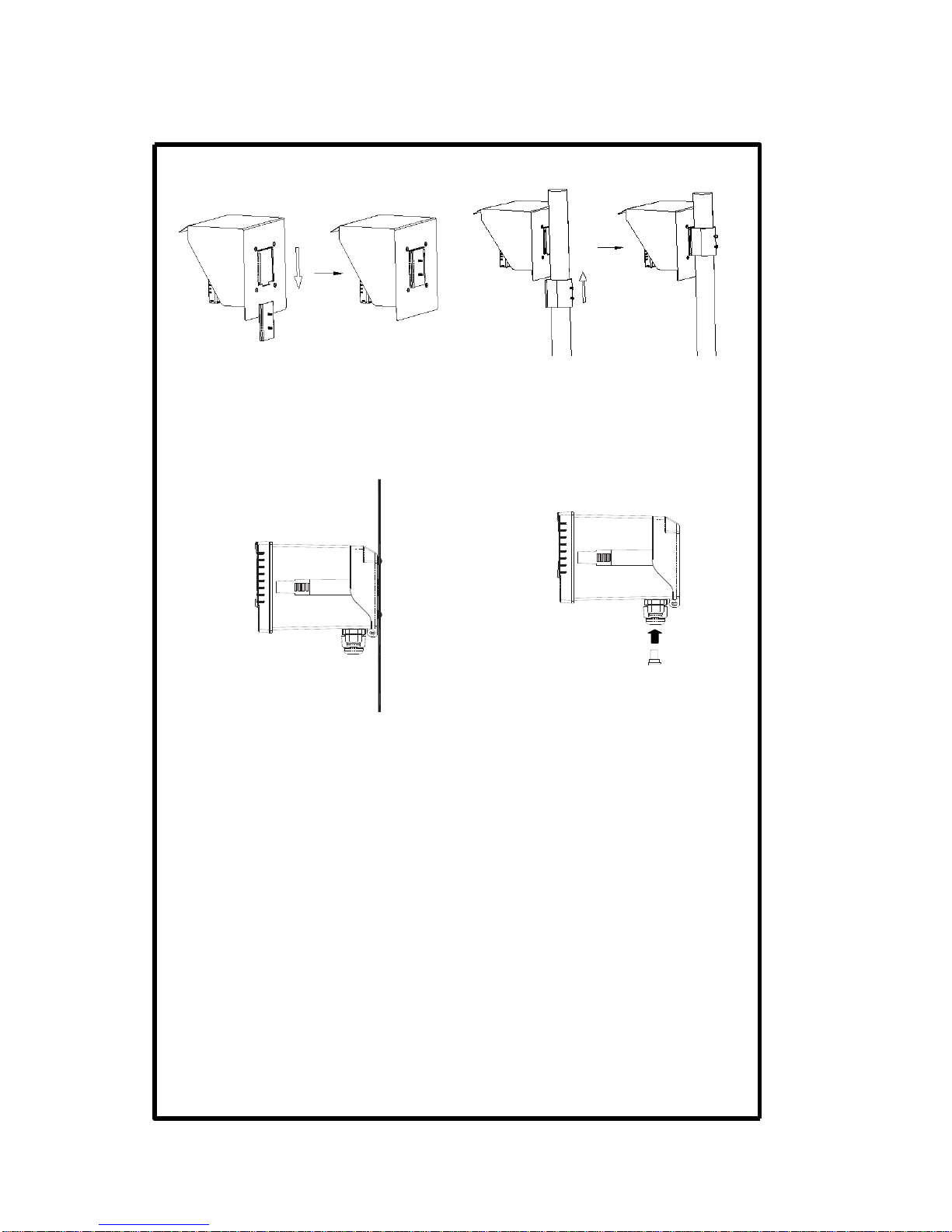
2.3 Illustration of wall mounting and pipe mounting
Installation of wall mounting
Fixed with 4 x M4 screws
Sun Shield (Pipe mounting, Optional)
( Order No.: 8-35 + 8-35-1 + 8-35-3)
Sun Shield (Wall mounting, Optional)
(Order No.: 8-35 + 8-35-2 + 8-35-3)
Insert the single hole rubber plug into
the unused cable gland, and tighten up
the cable gland to prevent from the
penetration of water vapor.
т
Page 15
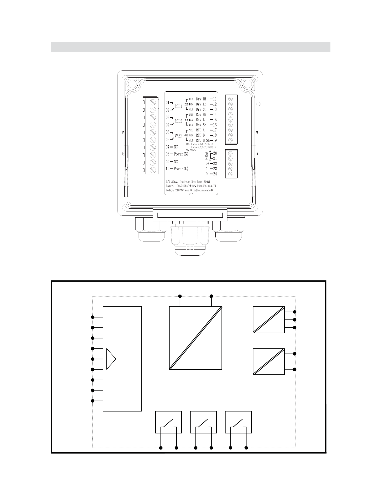
3. Overview of Conductivity transmitter EC-4110-I/EC-4110-ICON
3.1 Illustration of rear panel
3.2 Illustration of terminal function
WASH/ClnREL2REL1
POWER
AC
INPUT
POWER
4/20m
A
為
炼
RS-485
D+(B)
G
D-(A)
Drv Hi
Drv Lo
Drv S
h
Rev Hi
Rev Lo
Rev S
h
RTD A
RTD B
RTD B S
h
кй
Page 16
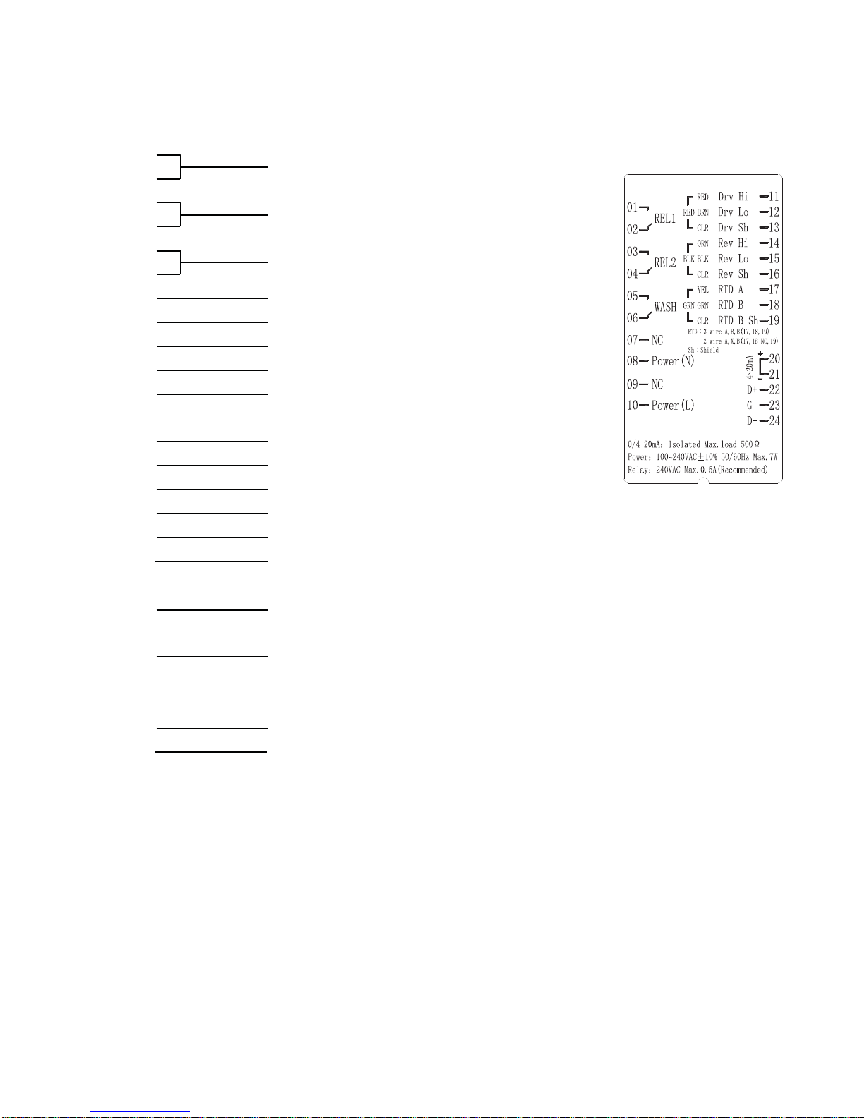
3.3 Description of terminal function
炿烀
REL1: First alarm control, the contact for an
external rela
y
炿烁
炿烂
REL2: Second alarm control, the contact for an
external rela
y
炿烃
炿烄
WASH: Wash relay contact for an external relay
炿烅
炿烆
NC: None contact
炿烇
Power(NĪĻ100~240VAC Power supply terminal
炿烈
NC: None contact
烀炿
Power(L
ĪġĻ
100~240VAC Power supply terminal
烀烀
烀烁
烀烂
Drv Sh: Shield
烀烃
Drv Hi: Sensor receive coil terminal, High
烀烄
Drv Lo: Sensor receive coil terminal, Low
烀烅
Drv Sh: Shield
烀烆
RTD A: Three-wiring temp. probe terminal A
烀烇
RTD B: Three-wiring temp. probe terminal B
烀烈
RTD B Sh: Three-wiring temp. probe terminal B Shield
烁炿
4~20mA +terminal: Master measure current output terminal +, for an
external recorder or PLC control
烁烀
4~20mA – terminal: Master measure current output terminal -, for an
external recorder or PLC control
烁烁
D+(B): RS-485 output D+(B)
烁烂
G: RS-485 output GND
烁烃
D-(A): RS-485 output D-(A)
Temp. probe is PTC1000/PTC100(three-wiring diagram contacts 17 RTD A, 18 RTD B, and 19
RTD B Sh.)
Temp. probe is NTC30K(two-wiring diagram contacts 17 RTD A and 19 RTD B Sh.)
Temp. probe is PTC1000/PTC100(two-wiring diagram shorts with 18 RTD B and 19 RTD B Sh.)
Drv HiĻSensor drive coil terminal, High
Drv Lo
Ļ
Sensor drive coil terminal, Low
кк
Page 17
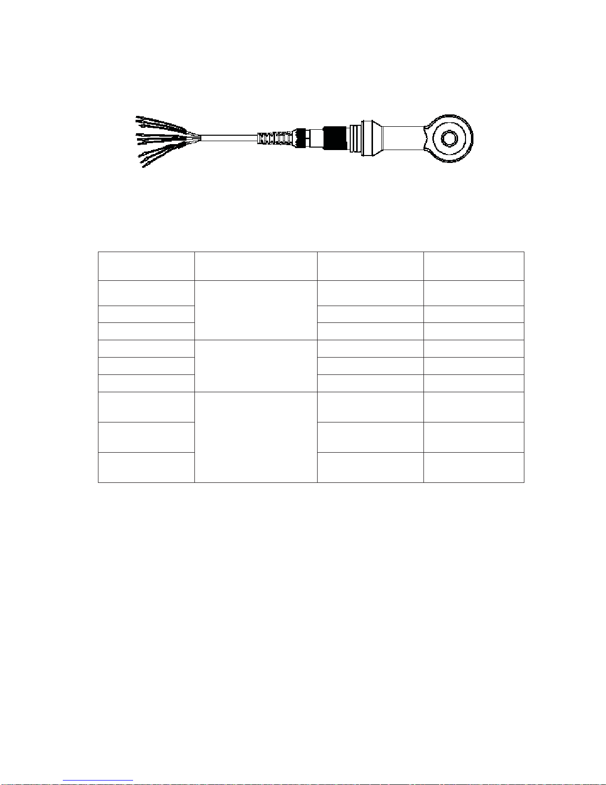
3.4 Wiring of cable
3.5 Circuit of cable
8-201-PFA-10 sensor assembly, 10M
Terminals Color of heat shrink tube Wire color Wire descriptions
Drv Hi
Red
Red Send H
Drv Lo
Brown Send L
Drv Sh
Clear Send SHIELD
Rev Hi
Black
Orange Receive H
Rev Lo
Black Receive L
Rev Sh
Clear Receive SHIELD
RTD A
Green
Yellow
PTC1000
RTD-A
RTD B
Green
PTC1000
RTD-B
RTD B Sh
Clear
PTC1000
RTD-B
кл
Page 18
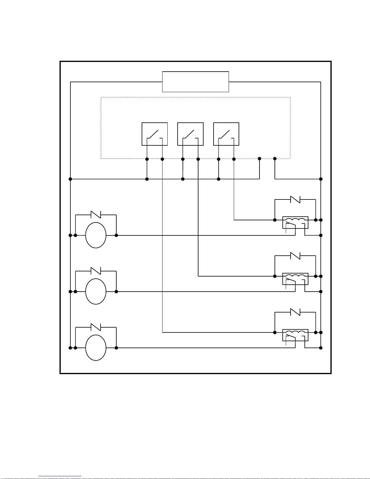
3.6 Illustration of electrical connection
Note: The transmitter built-in miniature relays is necessary to be repaired and replaced by professional technicians.
It is recommended to use an external relay (Power Relay) to activate the external equipments.
100V~240VAC
Relay 2Relay 1 WASH/Cln
100V~240VAC
Transmitter
Surge absorber
External relay
Surge absorber
External relay
Surge absorber
External relay
Cleaning device
Surge absorber
M
Dose feeder
Surge absorber
M
Dose feeder
Surge absorber
M
км
Page 19
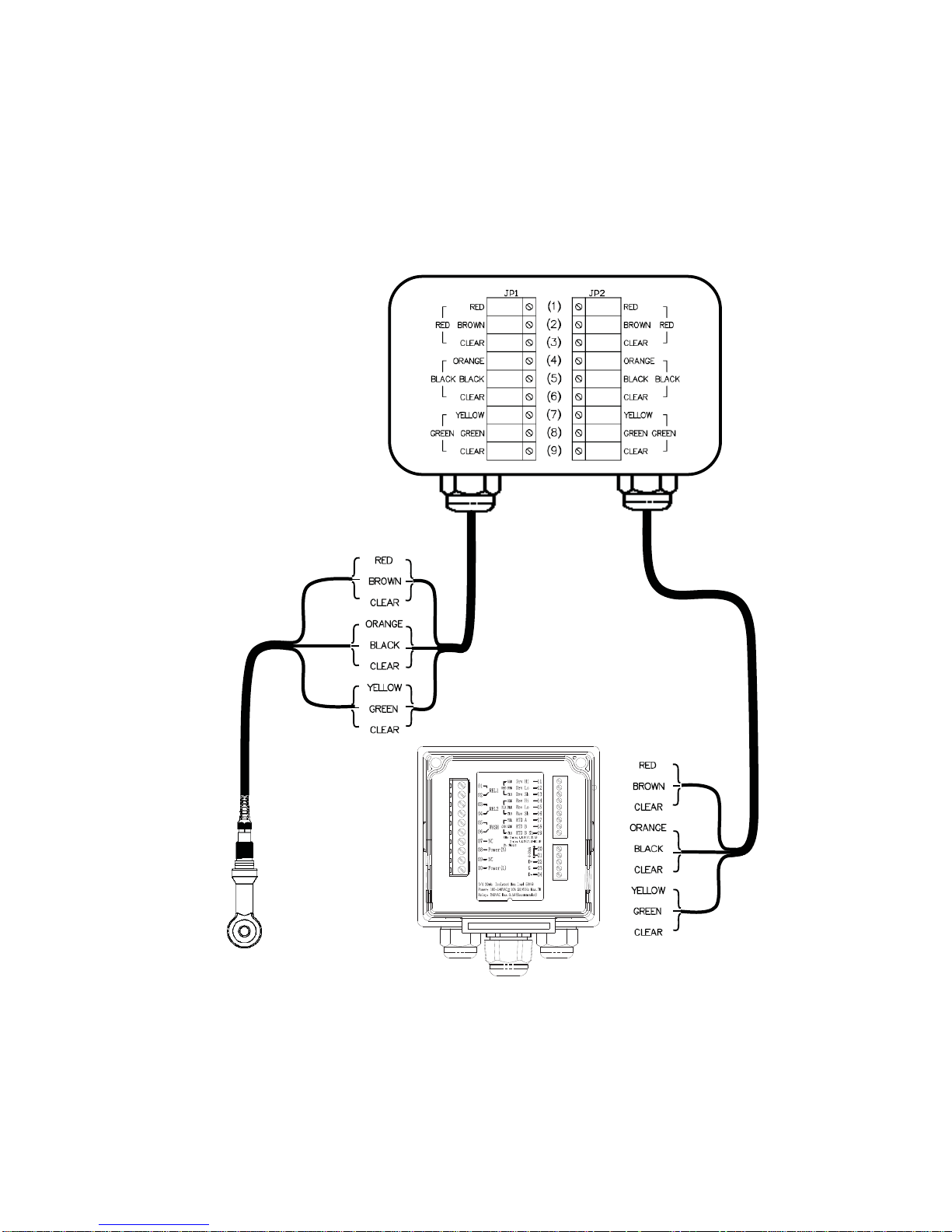
3.7 Wiring diagram of extension cable
When the length of signal cable needs extension(max. up to 50M), 8-09-9 square junction box
9T(there are 4 M4 fixed screws on the rear) and extension signal cable can be used. After
installation, it needs re-calibration of zero-point of the sensor and cell constant, or product
adjustments in field. Wiring diagram is as follows:
RED
BLACK
GREEN
RED
BLACK
GREEN
(8Ͳ201ͲPFAͲ10)10M
(ECͲ4110ͲI/ECͲ4110ͲICON)
11
12
13
14
15
16
17
18
19
8Ͳ09Ͳ9squarejunctionbox9T
Please inform specific
length of extension signal
cable as ordered.
кн
Page 20

4. Configuration
ġ ġ ġ ġ ġ ġ ġ ġ ġ ġ ġ ġ ġ ġ ġ ġ ġ ġ ġ ġ ġ ġ ġ ġ ġ ġ ġ
4.1 Illustration of front panel
4.2 Keypad
In order to prevent inappropriate operation by others, before the parameter setting and
calibration, the operation applies multi-keysĭġand coding protection if necessary. Description of
the key functions is in the following:
烉In the parameter set-up mode, pressing this key allows you exit parameter set-up mode
and back to Measurement mode.
Ļ In the Calibration mode, pressing this key allows you exit Calibration mode and back to
Measurement mode.
烉1. In the parameter set-up mode and Calibration mode, pressing this key to select
leftward or change to another page.
2. When adjusting value, press this key to increase the value.
烉1. In the parameter set-up mode and Calibration mode, pressing this key to select
rightward or change to another page.
2. When adjusting value, press this key to decrease the value.
烉Key for confirmation; pressing this key is essential when modifying data value or
selecting the parameter setting items in the window.
4.3 LED indicators:
ACT
烉
Washing operation relay(Clean) and dosing operation relay (Relay 1, Relay 2) indicator
B.L. : Light sensor; in the automatic display backlit mode, the lamp will light or go out as the
change of environmental brightness.
ко
Page 21
5. Operation
5.1 Measurement mode:
ġġġAfter all electrical connections are finished and tested, connect the instrument to the power
supply and turn it on. The transmitter will automatically entering measurement mode with the
factory default settings or the last settings from user.
5.2 Set-up menu:
ġġġPlease refer to the set-up instructions in Chapter 7. Press and simultaneously to
enter into set-up menu, and press to go press to back to measurement mode.
5.3 Calibration menu:
ġġġPlease refer to the calibration instructions in Chapter 8. Press and simultaneously to
enter into calibration menu, and press to go back to measurement mode.
5.4 Shortcuts:
1. In the measurement mode, if selecting MTC for temperature compensation mode, you may press
and to adjust MTC temperature value.
2. Under measurement mode, press continuously for 2 seconds to see the Logbook function
directly. Press key to back to measurement mode.
3. Under measurement mode, press continuously for 2 seconds to switch the display mode
from text mode, trace mode, and real-time chart display mode.
5.5 Default value:
5.5.1 Setting default value:ġġġġ ġġġġġġġġġġġġġġġġġġġġġġġġġġġ
Measurement mode: Conductivity@tref
Range: 2000mS
Temperature compensation: PTC1000
Temperature Coefficient: Lin, 2.00%
Relay 1: High point alarm: AUTO, SP1= 1000mS, Hys.=10mS
Relay 2: Low point alarm: AUTO, SP2 =100 mS, Hys.= 1.0 mS
Wash time: OFF
Analog current output (Cond/Res): 4~20 mA, 0~1000mS
RS-485: RTU, 19200,EVEN, 1, ID: 1
Date & Time: 2014/1/1 00:00:00
Digital filter: 0
Backlight setting: Off
Contrast: 0
Logbook: None
Auto back: Auto, 3 minutes
Code set-up: Off
5.5.2 Calibration default value:
ġ ġ ġ ġ ġ ġ ġ ġ ġ ġ ġ ġ ġ ġ ġ ġ ġ ġ ġ ġ ġ ġ ġ ġ
кп
Page 22

Cal Type: No Cal
Cal T emperature: None
Cell Constant: 2.700
Zero: 0.0ȝS
Auto back: Auto, 3 minutes
Code set-up: Off
Note: The factory default of calibration presetting is “No Cal”, and the cell constant setting is “2.700”. It means
that the user has not calibrated the sensor with the transmitter yet. When selecting standard solution or
directly adjusting cell constant to finish calibration, the display shows cell constant of the cell. It should
re-start a zero-point calibration in air after installation or maintenance, and the surface of sensor needs
cleaning without attachment with cleaning solutions during calibration.
кр
Page 23
6. Measurement display mode
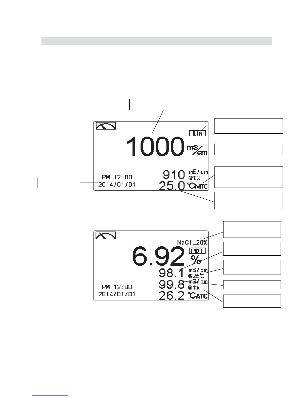
6.1 Text mode
The normal mode is for digit display, the content is as the following illustration. It mainly
includes main measurement value and unit, temperature measurement value and unit,
temperature compensation mode, and clock display.
The first line is main measurement to correspond to desired parameter, and the second
and the third line are auxiliary one to show related values but not necessary parameters.
The fourth line is to show temperature basically.
Main measurement unit
Temperature
compensation Mode
(
MTC/ATC
)
Temperature
measurement & unit
Main measurement
Clock display
Temperature
Compensation mode
Third measuring value
Second measuring
value
Second measuring
value unit
Third measuring value
unit
Conc. type and range
кс
Page 24

6.2 Real-Time Chart mode
Real-time chart mode is for dynamic display of real-time graphics. The duration is about three
minutes of the recent changes in measured values of the curve. Users can set the mode to its
corresponding Cond./Conc. measuring range (see section 7.4). The smaller the range is set, the
higher resolution of the display is. When entering setup or calibration mode and returning to
measurement mode, the real-time graphic will be re-updated. When the measured value exceeds a
set range of the upper and lower limit, the graphics will be presented in the upper and lower limits
dotted line. Real-time chart mode display is shown as below. There are also real-time measurement
value, & unit, and temperature value & unit which are displayed in the bottom of the screen. The
timeline in real-time graphic is divided into 12 depict, which is describe the range of
representatives of each of 1 / 4 minutes (15 seconds).
3 minutes of main measurement
record curve
Main measurement
value & unit
Temperature value
& unit
The current
instantaneous value
Upper limit
Lower limit
кт
Page 25
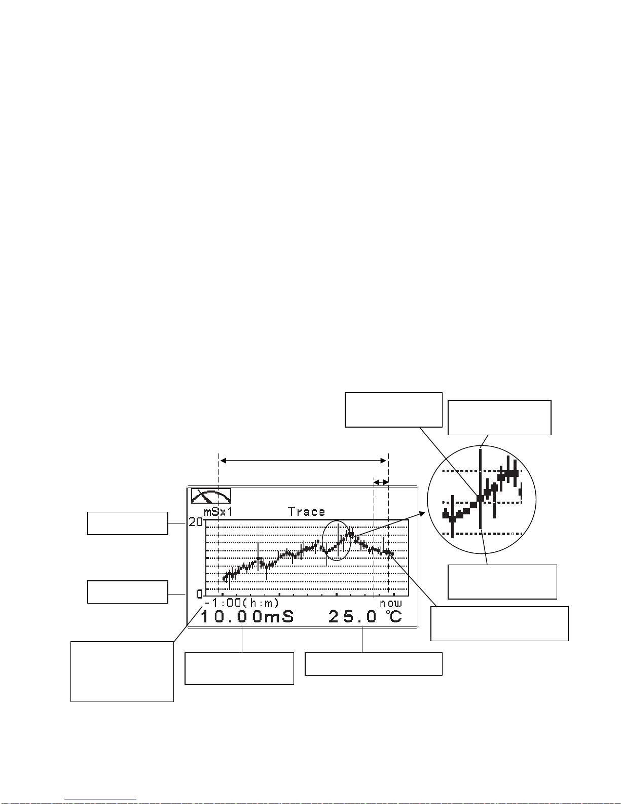
6.3 Trace mode
The feature of the trace mode is the record duration which can be set by the user (range from
three minutes, up to four weeks). The trend graphic records the measurements in the past T time.
The trend is recorded by the 60 group structure. Hence, each group of units is recorded in T/60
time interval. The trend line is constructed by all value data which is calculated to the average
(Mean Value), maximum (Max Value) and minimum (Min Value) form. When the latest T/60
record shows in the rightmost of the trend graphic, all the previous record will be moved to the left
side of the graphic. For example, T is set to 60 hours, then each set of records will be calculated to
the average, the maximum, the minimum values after one hour(T/60 = 1), each time interval.
Timeline of trends which is divided into 12 depictions showed on the horizontal axis of the display
is on behalf of each characterization interval T/12. So, every depiction has 5 (T/60) sets of records.
Users can set the corresponding Cond./Conc. measuring range in its set-up menu(see section 7.4).
The smaller the range is set, the higher resolution of the display is. The trace mode is shown as
below. There are also real-time measurement value, & unit, and temperature value & unit which
are displayed in the bottom of the screen.
Attention: When the time interval has been reset, the trend in the data will not be retained, it will
start a new trace record.
Note: The time display format (XX: XX) (hr: min), for example, appear as four weeks (672:00).
T/12
Trend recording interval
Whole Time(60 data record sets)
Main measurement
value & unit
Temperature value & unit
Upper limit
Lower limit
The max. value of
the T/60 interval
The min. value of
the T/60 interval
The mean value
of the T/60
The latest set of record
shown on the right sector
Record
duration(T), the
negative sign is to
mean the record
лй
Page 26
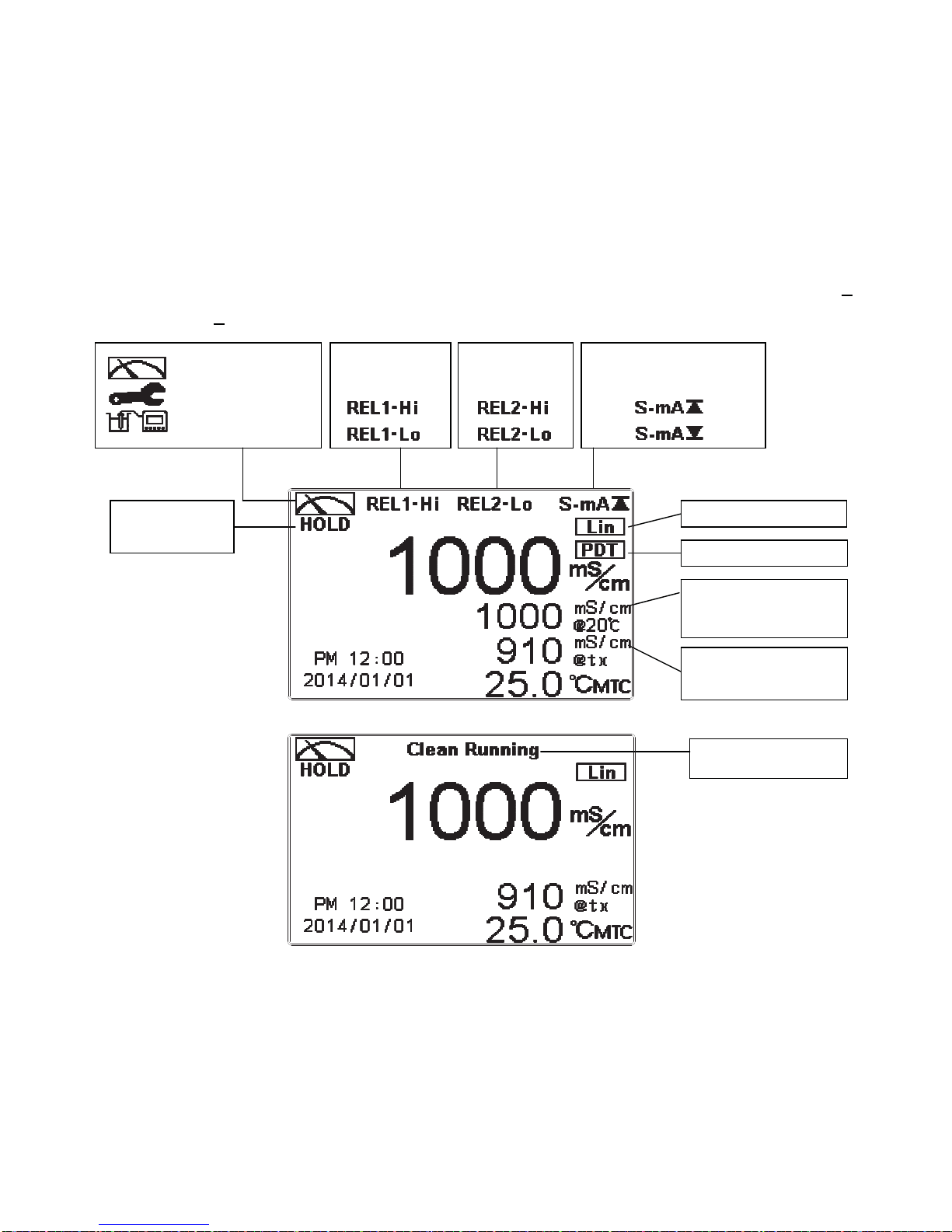
6.4 Warning symbols and text
1. When the clean function is activated, the display shows and twinkles the description, “Clean Running”.
At the same time, the ACT indicator LED lights up, and the transmitter automatically turns off Relay 1
and Relay 2 function. After finishing cleaning, the Relay 1 and Relay 2 will automatically back to
normal status.
2. When Relay 1/Relay 2 which is set in high setting point is in action, the display shows and twinkles the
description, “REL 1-HI/REL 2-HI”, and ACT indicator LED lights up. When Relay 1/Relay 2 which is
set in low setting point is in action, the display shows and twinkles the description, “REL 1-Lo/ REL
2-Lo”, and ACT indicator LED lights up.
3. When the Analog 1 current output exceeds the upper/lower limitation, the display twinkles ”
S-mA /
S-mA ” as an alarm.
Note: The “HOLD” warning text appears when clean function is activated, or when entering setup menu, or
when entering calibration menu. Under HOLD status, the corresponding display and output are as
follows:
1. Both Relay 1 and Relay 2 cease from action. If enter setting menu or calibration menu under clean status,
the instrument will stop clean status automatically.
2. The current output which is corresponding to measurement value remains at the last output value before
HOLD status.
3. The last signal output value of RS-485 interface is kept at the last output value before HOLD status.
ˑ
Control function
on hold
Product adjust ON
Compensation unit
mS/cm炯tref
conductivity with
temperature comp.
mS/cm炯tx
absolute conductivity
: measurement mode
: set-up mode
: calibration mode
Relay 1 high or
low point alarm
Relay 2 high or
low point alarm
Analog 1 output current
over range alarm
W
ash device in action
condition
лк
Page 27
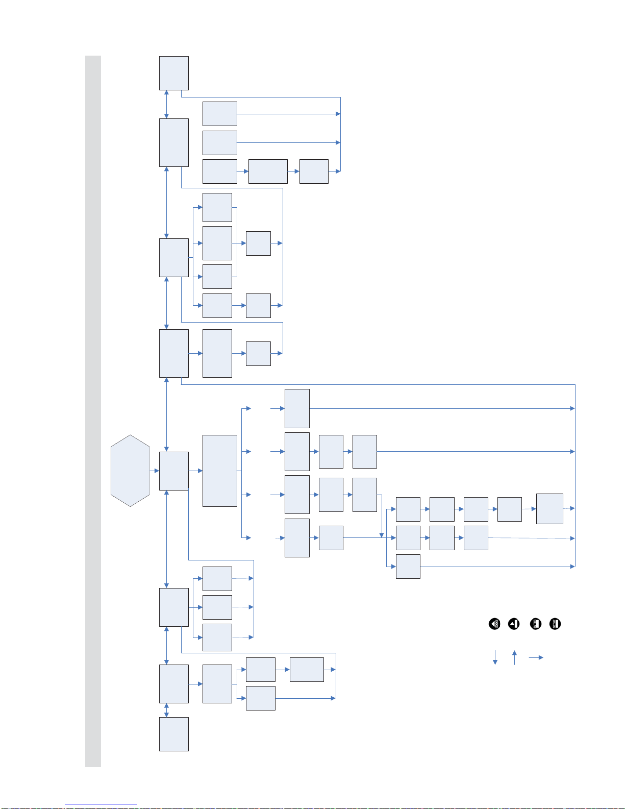
7. Settings
Block diagram of setting part 1
EC-4110-I
EC-4110-ICON
Overview
Mode Code Temperature
Input
Code
OFF ON
New
Code
MTC NTC PTC1000
Set
Temp.
Correct
Temp.
English
Traditi
onal
chinese
Simplif
ied
chinese
Return
Continue on next page
Language
烉
烉
烉
烉
Back to the previous
level / action
Product Adj.
Correct
SPAN
ON
Compensation
Linear
Comp.
Non-
Linear
Comp.
Input
linear
Comp.
Select
Product Adj.
ON or OFF
Set time
duration
Delete
all
YES
Select
Cond.@tref/Conc./TDS/
Salinity/Cond.@tx
Modes
Digital
Mode
Chart
Mode
Trace
Mode
Continue on next page
Relay 1
Cond.@tref
Cond.@tx
Mode
Conc.
Mode
TDS
Mode
Salinity
Mode
Select
Range
Set
Max
value
Set
Min.
value
Set
Max.
value
Set
Min.
Value
Input TC
Select
Solution
Select
Range
婧㔜
FACTOR
PTC100
No
Comp.
Input
TC
Value
Sub-display
ON or OFF
Sub-display
ON or OFF
Sub-display
ON or OFF
Sub-display
ON or OFF
лл
Page 28

Block diagram of setting part 2
Relay 1
Input
Relay1
SP value
Input
Relay1 Hys.
Value
Relay1
ON / OFF
Relay1
Test
Relay1
Hi / Lo
point
AUTO
Relay 2
Input
Relay2 Hys.
Value
Relay2
ON / OFF
Relay2
Test
Input
Relay2 SP
Value
Relay2
Hi / Lo
point
AUTO
Continue with previous page
Compensation Clean Current Output
Input
Clean
Close timing
Input Clean
Hys. Time
Interval
Clean
Test
Input
Clean
Timing
Input
Corresponding
Value to
0 or 4mA
Input
Corresponding
Value to 20mA
0/20 or 4/20mA
analog output
current
Clean
ON / OFF
AUTO
RS-485
RTU or
ASCII
Baud Rate
Parity
ID
Stop Bits
Clock
Set Month
Set Date
Set Time
Clock
ON or
OFF
ON
Digit Filter
Input
Back Light
Auto ON OFF
Input
Lightn
ess
Input
Sensitive
ness
Input
Lightness
Contrast
Input
Contrast
Logbook
Read
Historical
Data
Return
Input
Return
Time
Auto
Exit
Manual
Exit
Continue with previous page
Code
лм
Page 29

7.1 Entry of set-up menu
In the measurement mode, pressing the two keys and simultaneously allows
you enter the overview of current setting, and press to enter the set-up mode to modify
the setting if necessary.
Enter set-up menu
“Measurement (Mode)”
Pressġġġġ
Pressġġand simultaneously
Pressġġ
Pressġġor
Pressġġto confirm it
лн
Page 30

7.2 Security code of settings
After entering set-up mode, select “code” item, press to enter into code
procedure. The code pre-setting is 1111.
Note: The code of setting mode is prior to the code for calibration. That means that
the code of setting mode can be used for the code of calibration mode.
Enter “Language” Setup
Press or
Press to confirm it.
When a wrong password is
keyed in, the display shows
“Error Code”, press to
re-key in it, or press to
exit.
The first ‘0” of digits ‘0000” start
to twinkle. Press or to
adjust the value, and then press
to confirm it and continually key
in the next digit, and so on.
(Select to turn on or turn off
code protection function. If
you select turn on, please
key in a new code. There
will be a code requirement
showing in display when you
re-enter to the setup mode.
Key in the correct password
to enter into setup mode.)
Key in new password
Press to confirm it.
Press to confirm it.
Press to confirm it.
ло
Page 31

7.3 Language
Enter Language setup menu, select the system language from English, Traditional
Chinese and Simplified Chinese.
Enter “Measurement Mode” Setup
Press to confirm it.
Pressġ or ġġ
to select
language type
Press to confirm it.
Pressġ or ġġ
to select
language type
Press to confirm it.
Press to confirm it. Press to confirm it.
лп
Page 32

7.4 Mode
The default setting of measuring range is 2000mS/cm, and users can select the desired range
according to requirements from 2000mS, 999.9mS, 99.99mS, 9.99mS, ȝ6 or AUTO range
selection.
7.4.1 Conductivity with Temperature Compensation (Cond.@tref)
Conductivity with temperature compensation means that conductivity can be obtained by
linear or non-linear temperature compensation setting. (“temperature compensation
coefficient” and “temperature compensation reference temperature”, please refer to ch7.7
“Temperature Compensation Coefficient”.)
Enter setup of Mode, select “Cond.@tref” and measuring range from 2000mS, 999.9mS,
99.99mS, 9.99mS, 999.9ȝ6 or AUTO range selection, and then select display mode.
Select Trace Mode Select Chart Mode
Press to confirm it.
Press to confirm it.
Press to confirm it.
Press to confirm it.
Press to confirm it.
Press or to select
Cond.@tref
Press to confirm it.
Press to confirm it.
Press to confirm it.
Press to confirm it.
Press to confirm it.
Press to confirm it.
Press to confirm it.
Press or to input
upper limit
Press or to select
to turn the auxiliary subtitle
on or offġ
Press or to select
measuring range or auto range
selectionġ
Press to confirm it.
Press or to input
lower limit
Press to confirm it.
лр
Page 33

Enter ȾProduct Adjustment.ȿSetup
Select Digital Mode
Digital Mode
Chart Mode Trace Mode
Press or to select
display modeġ
Press to confirm it.
Press to confirm it.
Select YES & Press
to confirm it.
Press to confirm it.
Press to confirm it.
Press to confirm it.
Select NO to preserve the
setting and previous data
Press to confirm it.
To set record duration T,
press or
to adjust the hour value ,
press to confirm
and move to minute
adjustment part.
лс
Page 34

7.4.2 Absolute Conductivity(Cond.@tx)
Absolute conductivity is to present the actual conductivity without temperature compensation of
a measured solution.
Enter setup of Mode and select absolute conductivity ” Cond.@tx”. Then select the measuring
range from 2000mS, 999.9mS, 99.99mS, 9.99mS, ȝ6 or AUTO range selection and display
mode.
Select Trace Mode
Select Digital Mode
Select Chart Mode
Press to confirm it.
Press to confirm it. Press to confirm it.
Press to confirm it.
Press to confirm it.
Press to confirm it.
Press to confirm it.
Press to confirm it.
Press or to input
upper limit
Press or to input
lower limit
Press or to select
Cond.@txġ
Press or to select
to turn the auxiliary subtitle
on or offġ
Press or to select
measuring range or auto range
selectionġ
Press or to select
display modeġ
Press to confirm it.
Press to confirm it.
Press to confirm it.
Press to confirm it.
лт
Page 35

Press to confirm it.
EnterȾProduct AdjustmentȿSetup
Digital Mode Chart Mode Trace Mode
To set record duration T,
press or
to adjust the hour value ,
press to confirm
and move to minute
adjustment part.
Select YES & Press
to confirm it.
Select NO to preserve the
setting and previous data
Press to confirm it.
Press to confirm it.
мй
Page 36

7.4.3 Concentration (EC-4110-ICON Only)
Enter setup of Mode and select “Conc.” measuring mode, optimum measuring solution,
varieties and concentration.
Built-in measuring ranges are listed below: NaCl_28%(0-28%), HCl_18%(0-18%),
HCl_39%(22-39%), HNO3_30%(0-30%), HNO3_96%(35-96%), NaOH_24%(0-24%),
NaOH_50%(15-50%), H
2SO4
_37%(0-37%), H2SO4_88%(28-88%), H2SO4_99%(89-99%),
H3PO4_35%(0-35%) or Defined, and then select display mode.
As conductivity or concentration exceeds boundary limits of its measuring range, the
measured value twinkling will represent an error warning, however, please note that “Defined”
is without measuring range limitation and an error warning.
Concentration conversion boundary values of each solution vary with the changes of
temperature.
Press to confirm it.
Select Trace Mode
Select Digital Mode
Select Chart Mode
Press to confirm it.
Press to confirm it.
Press to confirm it.
Press to confirm it.
Press to confirm it.
Press to confirm it.
Press or to select
Conc.
Press or to turn the
auxiliary subtitle on or off
Press to confirm it.
Press to confirm it.
Press or to input
upper limit
Press or to input
T.C. value
Press or to select the solution
Press or to select display mode
Press to confirm it.
Press to confirm it.
мк
Page 37

Press to confirm it.
Press to confirm it.
EnterȾProduct AdjustmentȿSetup
Digital Mode Chart Mode Trace Mode
Press to confirm it.
Press to confirm it.
Press to confirm it.
Press to confirm it.
Press to confirm it.
Press or to input
lower limit
Select NO to preserve the
setting and previous data
Select YES & Press to
confirm it.
Press to confirm it.
To set record duration T,
press or
to adjust the hour value ,
press to confirm
and move to minute
adjustment part.
мл
Page 38

7.4.3.1 Defined concentration table
If the measured sample information is not listed in built-in table of the transmitter, users can
input their defined table. Defined table can be input data with temperature of measured
solution, sort ascending or sort descending, from 1~9 temperature table. At least two or up
to nine conductivity and concentration conversion data are included at each temperature
(more data, more approximate the solution concentration, higher conversion resolution), and
each data include one concentration and its corresponding conductivity.
Conductivity or concentration needs to be input in ascending or descending order. If users’
measured solution only has one data (one concentration and its corresponding conductivity),
they need to set linear temperature compensation coefficient for that in order to make the
temperature compensation.
Defined table default setting which includes 9 data is for Hydrofluoric Acid at 25ɗ. Users
can revise the data, in addition, they need to input linear temperature compensation
coefficient (refer to HF table); for users only with one data, after inputting corresponding
value of conductivity and concentration, it also requires T.C. coefficient.
If the data are attained by two or more temperature points, there is no need to input T.C.
coefficient because the unit can calculate the corresponding concentration value and
conductivity with reference temperature based on conversion data in different temperature.
Once default conversion table for HF is being changed, it needs re-input again.
If the temperature, conductivity and concentration of test solution are approximate to
measured solution, higher & more accurate conversion relation can be required.
Press to confirm it.
Press or to input T.C. coefficient
Press to confirm it.
Press to confirm it.
Press to confirm it.
Press to confirm it.
Press to confirm it.
Press to confirm it.
Press or to select
Conc.
Press or to turn the
auxiliary subtitle on or off
мм
Page 39

Press or to set the
number of Conc. points
one temp. point two or more temp. points
Press or to select
Defined.
Press to confirm it.
Press to confirm it.
Press or to set the
unit of Conc.
Press or to set desired number
of tables
Press or to set the
unit of conc.
Press to confirm it.
Press to confirm it.
Press to confirm it.
Press to confirm it.
Press to confirm it.
Press or to set the
T.C. coefficient
Press or to set the
number of Conc. points
Press to confirm it.
Press to confirm it.
Press to confirm it.
Press to confirm it.
Press to confirm it.
мн
Page 40

If the temperature is not input in ascending or descending order, there shows Temp. Error on the
display screen.
If the conductivity is not input in ascending or descending order, there shows Cond. Error on the
display screen.
If the concentration is not input in ascending or descending order, there shows Conc. Error on the
display screen.
Current T able
T ota l Tables
Temp. of the Table
Points
Input Conc.
Save & Exit
Input Corresponding
Cond. to Conc.
Save & Next Page
one temp. point two or more temp. points
Press to confirm it.
мо
Page 41

Concentration %
Hydrofluoric Acid
HF Solution mS/cm at 25ɗ
ɗ
0.0001 0.01
0.0003
0.03
0.001
0.099
0.003
0.290
0.01
0.630
0.03.
1.49
0.1
2.42
0.3
5.1
1.0
11.7
3.0
34.7
5.0
62.0
10.0
118.0
20.0
232.3
30.0
390.0
*Please refer to the concentration and conductivity conversion table of Hydrofluoric Acid (HF)
(for reference only, users need to revise it on their own)
*T.C. coefficient for common solution is within 1.8~2%, but it is 0.7% for Hydrofluoric acid (HF).
Besides, according to the changes of concentration, T.C. coefficient changes and thus users need to
adjust it depending on the requirements. For example, T.C. coefficient for 0.5%, 1.0%, 3.0% HF is
about 0.70%, 0.73%, 0.74%. Users can attain the T.C. coefficient depending on actual situation of
measured solution.
*T.C. coefficient for Hydrofluoric Acid (HF)
(for reference only, users need to revise it on their own)
ġ
ġ
мп
Page 42

7.4.4 TDS
Enter the setup of Mode, select TDS measuring mode and units from ppm or ppt and set the
TDS constant. The default TDS constant is SSPȝ6.
Press to confirm it.
Press to confirm it.
EnterȾProduct AdjustmentȿSetup
Press or to select TDS
Press to confirm it.
Press to confirm it.
Press to confirm it.
Press to confirm it.
Press or to turn the
auxiliary subtitle on or off
Press to confirm it.
Press to confirm it.
Press or to select
the unit
мр
Page 43

7.4.5 Salinity
Enter setup of Mode and select Salinity measuring mode.
Press to confirm it.
Press or to turn the
auxiliary subtitle on or off
Press to confirm it.
Press to confirm it.
EnterȾProduct AdjustmentȿSetup
Press to confirm it.
Press to confirm it.
Press or to select TDS
мс
Page 44

7.5 Product Adjustment
Enter setup of Product Adjustment to make the fine adjustment of the measurement reading.
There is no need for users to take out the sensor from the field and calibrate it. Via this function
the measuring values from the field can be compared to the result that came from the sampling
and directly adjusted to the same value. If turning on this function, there shows the symbol
“PDT” on the display screen.(please refer to ch6.4 “Warning symbols and text”).
The inductive sensor applies electromagnetic effects to measure the conductivity of a sample
solution which can be affected by length of signal cable and the distance between a sensor and
the shell of pipe, making an influence on the cell factor and measuring value. At the moment,
Product Adjustment can be used to calibrate the measuring value without changing the cell
factor.
Users may compare the reading with the
actual measured value. Press or
to adjust the Cell Factor( a cell constant’s
multiplier) in the main display in order to
modify the reading of measurement
which shows in the bottom part of
display.
Press to confirm it.
Press to confirm it.
Press to confirm it.
Press to confirm it. Press to confirm it.
Press to confirm it.
Press to confirm it.
EnterȾTemperatureȿSetup
Press or
to switch on or
switch off.
мт
Page 45

7.6 Temperature
Enter setup of “Temperature” to select temperature probe types. Select from 37&.ȍ (PT-1000),
37&ȍ (PT-100), or NTC(NT30K) for Auto Temperature Compensation or MTC(Manual
Adjustment).ġ
Press to confirm it.
Press to confirm it.
Press to confirm it.
Press to confirm it.
Press to confirm it. Press to confirm it.
Press to confirm it.
Press to confirm it.
EnterȾTemperature Compensation CoefficientȿSetup
Press to confirm it.
Use standard thermometer to test
the actual temperature of the
solution, and press or
to input the correct temperature
value.
If necessary, compare with
the actual temperature
value tested by standard
thermometer.
Press or to
input the modified value.
Press to confirm it.
нй
Page 46

7.7 Temperature Compensation Coefficient
The default setup of temperature compensation reference temperature is 25 䉝, and temperature
compensation coefficient is 2.00%.
Enter setup of Temperature Compensation Coefficient mode and select T.C. coefficient from
Linear, Non-Linear or No according to measurement requirements. Normally, select linear
compensation for Conductivity measurement (Cond.).
Temperature coefficient (hereinafter referred to as TC): Conductivity of solution increases with
rising temperature. The relationship is as follows:(reference temperature ”t
ref
” is 25䉝, users can
change depending no requirements)
How to get TC of solution:
C
tref
Conductivity at reference temperature
Ct = C
tref
^Į7炼t
ref
) }
C
t1
&RQGXFWLYLW\DW7Û&
T
1
Measured solution temperature
Į &
t2炼Ct1
) / Ct1 ( T2炼t
ref
)炼Ct1 ( T1炼t
ref
)
C
t2
&RQGXFWLYLW\DW7Û&
T
2
Measured solution temperature
Į Temperature compensation
coefficient
Take an example for 0.01M KCl. Set the TC of the instrument to non-compensated炷Lin, 0.00炴炸,
and control the temperature at C
t1
Û&DQGDWCt2Û&ġC
t1
means the measurement value at 20Û&6XFK
as
C
20
= 1278ȝ6&t2 means the measurement value at 30Û&6XFKDVC
30
= 155ȝ6%DVHGRQWKH
IRUPXODVDERYHĮ烌1.94%.
Linear compensation range: 0.00炴焍40.00炴
Temperature compensation range(C
tref
): PT1000/PT100/MTC 0 䉝焍200 䉝
NTC30K 0 䉝焍130 䉝
Press to confirm it.
Press to confirm it.
1278(30炼25) 炼1552(20炼25)
1552炼1278
ǘ100 = 1.94
Ƞ烌
Press to confirm it.
Press to confirm it. Press to confirm it.
Pressġ or ġġ
to select
Pressġ or ġġ
to select
нк
Page 47

Linear Mode Non-Linear Mode No Mode
ņůŵŦųȾRelay 1ȿŔŦŵŶűġ
Press to confirm it.
Press to confirm it.
Press to confirm it.
Press to confirm it.
Press to confirm it.
Pressġ or ġġ
to set compensation
coefficient.
MAX: 40.00%
Pressġ or ġġ
to set compensation
temperature
нл
Page 48

7.8 Relay 1
Enter setup of Relay 1. Select the item to turn on or turn of the relay 1 function. If you select to
turn on the relay 1, then select for using relay 1 as “High set-point” alarm or “Low set-point”
alarm. Set the value of set-point (SP) and Hysteresis (Hys.). The relationship between parameters
can refer to an explanatory diagram of the box (as a high point alarm).
Press to confirm it.
Press to confirm it.
Press to confirm it.
Press to confirm it.
Press to confirm it.
Press to confirm it.
Press to confirm it.
Press to confirm it.
High Point Alarm Control
off off
on
on
SP
Hys.
%/mS/ȫS/ppm/ppt
t (sec)
ņůŵŦųȾRelay 2ȿŔŦŵŶűġ
SelectġAUTO.ġ
Press to confirm it.
Press to confirm it.
Press to confirm it.
Press ġ or
to select Hi point
or Lo point alarm.
Press or
to adjust Hysteresis
(Hys.) value
Press or to adjust
set-point (SP) value.
If the measuring range of
conductivity is set as AUTO,
then it needs to be set unit
ȝ6FPRUP6FPYDOue, and
decimal point by orders.
Press ġ or to
select to activate a test on
REL1. If “ON”, the relay
1 is in action, and the
“ACT” indication light
will light up.
нм
Page 49

7.9 Relay 2
Enter setup of Relay 2. Select the item to turn on or turn of the relay 2 function. If you select to
turn on the relay 2, then select for using relay 2 as “High set-point” alarm or “Low set-point”
alarm. Set the value of set-point (SP) and Hysteresis (Hys.). The relationship between parameters
can refer to an explanatory diagram of the box (as a high point alarm).
Press to confirm it.
Press to confirm it.
Press to confirm it.
Press to confirm it.
Press to confirm it.
Press to confirm it.
Press to confirm it.
Press to confirm it.
Press to confirm it.
Press to confirm it.
Low Point Alarm Control
off
SP
Hys.
%/mS/ȫS/ppm/ppt
t (sec)
off
on
on
ņůŵŦųȾCleanȿŔŦŵŶűġ
Select AUTO.
Press to confirm it.
Press to confirm it.
Press ġ or
to select Hi point
or Lo point alarm.
Press ġ or
to activate Relay 2
Press or
to adjust Hysteresis
(Hys.) value
Press ġ or to
select to activate a test on
REL2. If “ON”, the relay
2 is in action, and the
“ACT” indication light
will light up.
нн
Page 50

7.10 Clean
Enter setup of “Clean” function. Select the icon to turn on or turn off the clean function. If you
select “Auto” turning on, then set the timer of the clean function including automatically turning
on time and turning off time, and set the Hysteresis value (Hys.).
Note: When the clean function is turned on, if any value is set to be 0, the instrument will automatically
turn off this function. When the clean function is activated under measurement mode, there is a “Clean
Running” message showing on top of the display. The measurement value will be remained at the last
measured value before cleaning. If enter setting menu or calibration menu under clean status, the
instrument will stop clean status automatically.
Press to confirm it.
Press to confirm it.
Press to confirm it.
Press to confirm it.
Press to confirm it.
Press to confirm it.
Press to confirm it.
Press to confirm it.
Press to confirm it.
Press to confirm it.
on off on off on
off off
on on
off
T
on Thys
T
off
Ton T
hys Toff
T
off
Clean Timer Control
Relay
Contact
Timer
Settin
g
s
Measure
Action
Enter “Current Output” Setup
Press ġ or
to select to activate
Clean or not.
Press ġ or to
adjust the auto turning
on time.
Press to confirm
the minute part, and
move to adjust the
second part.
Press ġ or to
adjust the auto turning
off time.
Press to confirm
the minute part, and
move to adjust the
second part.
Press to confirm it.
Press or to
adjust duration time for
Hysteresis (Hys.)
Press to confirm the
minute part, and move to
adjust the second part.
Press ġ or to
select to activate a test of
Clean or not. If “ON”, the
Clean function is in
action, and the “ACT”
indication light will light
up.
но
Page 51

7.11 Current Output
Enter setup of Current Output. Select 0~20mA or 4~20mA current output. Set the related value
to the range of Cond. measurement. If the range of the Cond. measu rement is to be set smaller,
the resolution of current output is higher. When the measured value exceeds the higher range
limit, the current will remain approximately 22mA output. When the measured value exceeds
the lower range limit, under 0~20mA mode the current output will remain 0mA output; while
under 4~20mA mode the current output will remain approximately 2mA output. The
exceptional output value can be used as a basis for failure determination. Under
HOLD(measurement) status, the current output maintain the last output value before HOLD
status. However, in order for convenience of insuring the current setting of an external recorder
or of a PLC controller, the current output will be 0/4mA or 20mA under the analog output setup
menu.
Press to confirm it.
Press to confirm it.
Press to confirm it.
Press to confirm it.
Press to confirm it.
Press to confirm it.
Press to confirm it.
Press to confirm it.
Press ġ or
to select to current
output range,
0-20mA or 4-20mA.
Press or to set
the lower limit of Cond.
value relative to 4.0mA
output signal. If the
measuring range of
conductivit y measurement
is set as AUTO, then it
needs to EHVHWXQLWȝ6FP
or mS/cm), value, and
decimal point by orders.
Press or to set
the lower limit of Cond.
value relative to 0.0mA
output signal. If the
measuring range of
conductivity measurement
is set as AUTO, then it
QHHGVWREHVHW XQLWȝ6/cm
or mS/cm), value, and
decimal point by orders.
нп
Page 52

Press to confirm it.
Press to confirm it.
4-20mA
0-20mA
EnterȾRS-485 CommunicationȿSetup
Press to confirm it.
Press or to
set the upper limit of
Cond. value relative to
20.0mA output signal.
нр
Page 53

7.12 RS-485 Communication
Enter setup of RS-485 communication. According to the Modbus protocol, set the Transmitting
Mode, Baud Rate, Parity, Stop Bit, and ID number. About the detail of Modbus protocol, please
refer to Ch9 Modbus Protocol. If under HOLD status, the measurement signal output maintains
the last output value before HOLD status.
Press to confirm it.
Press to confirm it.
Press to confirm it.
Press to confirm it.
Press to confirm it.
Press to confirm it.
Press to confirm it.
Press to confirm it.
Press to confirm it.
Press to confirm it.
EnterȾClockȿSetup
Press to confirm it.
Press to confirm it.
Press or to select
2400, 4800, 9600, or
19200 for Baud Rate.
t
t
Press or to select
RTU or ASCII mode
Press or to select
Even, Odd, or None for
Parity
t
Press or to
select 1 Bit or 2 Bit for
Stop Bit.
Press or to set
the ID number of the
transmitter. The valid
value is from 001 to 247.
нс
Page 54

7.13 Clock
Enter setup of Date/Time(Clock). Set the “Year”, “Month”, “Date”, “Hour”, and “Minute” time.
Note: If you select to turn off the clock function, there will not display clock under measurement
mode. The calibration time of calibration record will also show ”OFF” under calibration
overview display.
Note: With the EC-4110-ICON model, the transmitter may keep the clock in operation even
when encountering power failure. Only when the inner batter y is out of power, the clock may
stop operation. Then, please replace the 3V CR2025 Li batter inside the transmitter.
Press to confirm it.
Press to confirm it.
EnterȾDigital FilterȿSetup
Press to confirm it.
Press to confirm it.
Press to confirm it.
Press to confirm it.
Press to confirm it.
Press to confirm it.
Press to confirm it.
Press or to
set the year.
Select ON & Press to confirm it.
Press or to
set the month part, and
press to move to
adjust the date part.
Press or to
set the hour part, and
press to move to
adjust the minute part.
Press or to
activate the function or
not
нт
Page 55

7.14 Digital Filter
Enter the setup of Digital filter. You may select the number of sample to be averaged each time
to become a reading which is gradually counted in order to increase the stability of
measurement.
Note: “0” represents auto setting according to the conductivity measurement.
Press to confirm it.
Press to confirm it.
Press to confirm it.
EnterȾBack LightȿSetup
Press to confirm it.
Press or to
set the number of
sample to be averaged.
ой
Page 56

7.15 Back Light
Enter setup of backlight display. According to users’ requirements, the brightness of display
(-2~2, dark~bright) and sensitivity of the sensitization sensor(-2~2, insensitive~sensitive) can be
set. On OFF or AUTO backlight mode, if there is a keystroke, then it activates the touch-on state,
activating the backlight. If there is no keystroke for 5 seconds, the display will be back to the
original backlight setting status.
Pressġ or ġġ
to select -2, -1, 0,
1, 2, five backlight
brightness levels
Pressġ or ġġ
to select -2, -1, 0,
1, 2, five backlight
brightness levels
Press to confirm it.
Press to confirm it.
Press to confirm it.
Press to confirm it.
Press to confirm it.
Press to confirm it.
Press to confirm it. Press to confirm it.
Press to confirm it.
Press to confirm it.
EnterȾContrastȿSetup
ON setting:
The backlight is always on
OFF setting: The backlight is off. When there is a keystroke, it enters to
the touch-on status.
AUTO setting:
According to the ambient light, activate or deactivate the
backlight. When there is a keystroke, it enters to the
touch-on status.
Press or
to select
backlight mode.
Press or
to select
backlight mode.
Pressġ or ġġ
to select -2, -1, 0, 1, 2,
five Backlit sensitization
levels.
ок
Page 57

7.16 Contrast
Enter setup of Contrast. You can set the contrast of display according to your need. (-2, -1, 0, 1,
2, light to dark).
Press to confirm it.
EnterȾLogbookȿSetup
Press to confirm it.
Press to confirm it.
Press to confirm it.
Pressġ or ġġ
to select display
contrast level.
ол
Page 58

7.17 Logbook
Enter setup of Logbook. Users may look up the relative 50 records of the transmitter showed on
the display screen or read by Modbus. The event descriptions are as follows. If users would like
to use Modbus to read the event records, they need to type the serial number 0028 first, and then
they can attain the corresponding event records from 0029H~002FH. Serial number 1 means the
latest event, serial number 2 means the former event, and so on.
Event Description Modbus code
Mea mode Measurement mode 00
Set mode Setting mode 01
Cal mode calibration mode 02
Power On The unit is powered up 03
Power Off The unit is out of power 04
Cond_mA Over Current is over range 05
Error 1 Unstable readings as calibration 06
Error 2
1. Cell factor exceeds the upper/lower limit
2. Temperature is over range
07
Error 3 Wrong password 08
Conc_mA Over Current is over range 09
Error 9 The unit is broken 10
Modbus Write Modbus read-in action 13
EnterȾReturnȿSetup
Press to confirm it.
Press to confirm it.
Pressġ or ġġ
to select different
page
ом
Page 59

7.18 Return
Enter setup of auto return mode (Return) to set the function that the instrument automatically
exit the setup menu after a period of time without pressing any key. The “Manual Exit” means
that it needs to exit setup menu manually, while “Auto” means that the display automatically
exit the setup menu and back to measurement mode after a period of time without pressing any
key.
Press to confirm it.
Press to confirm it.
Press to confirm it.
Press to confirm it.
Press to confirm it.
EnterȾCodeȿSetup
Press to confirm it.
Press to confirm it.
Pressġ or
to select Auto return
or manual exit.
Pressġ or
to adjust “minute”
part, and press
to confirm it and move
to” second” part.
он
Page 60

8. Calibration
Block diagram of Calibration
EC-4110-I
EC-4110-ICON
Information
Cell
Constant
Std.
Solution
MTC Mode
Cell
Constant
Adjustment
Return
Return
Time
Input
Auto
Manual
Exit
Code
Input
OFF ON
New
Code
Back to previous
level of action
烉
烉
烉
烉
Set
Temperature
ATC Mode
MTC Mode
Ser
Temperature
Select
Std.
Solution
ATC Mode
Calibration
Show
Cell
Constant
Std.
Solution
Adjustment
Std.
Solution
Adjustment
Zero
Zero-point
Calibration
1
оо
Page 61

8.1 Enter calibration setup menu
In the measurement mode, pressing the two keys and simultaneously allows you to
enter theġCalibration Information. If you do not need to re-calibrate the measurement system, press
to go back to measurement mode. If you need to re-calibrate the system, press to enter to
the calibration setup menu. (If the calibration time shows “OFF”, it represents that the clock function
has been turned off.)
Measurement mode
Enter Calibration setup menu
Press and simultaneously
Press to confirm it.
Press to go back to
measurement mode
2
оп
Page 62

8.2 Security password of calibration (Code)
Select the Code (password) icon after entering calibration setup mode. Select to activate code
function or not. The default Calibration setting code is “1100”.
Press or to
select
Press to confirm it.
Press to confirm it.
Press to confirm it.
Press to confirm it.
Enter “Cell Constant Calibration”
Press to confirm it.
The first ‘0” of digits ‘0000” start
to twinkle. Press or to
adjust the value, and then press
to confirm i t and contin ually key
in the next digit, and so on.
If you input a wrong code, then
the display shows a “Error
Code” message. Press
to restart inputting another
code, or press to exit
the calibration menu.
(Select to turn on or turn off code
protection function. If you select
turn on, please key in a new code.
There will be a code requirement
showing in display when you
re-enter to the setup mode. Key in
the correct password to enter into
calibration setup menu.)
Input the new code.
The steps are as above.
3
ор
Page 63

8.3 Zero-Point Calibration
The inductive sensor connected with the transmitter needs to make a zero point calibration in the
air. Before calibration, it is necessary to make sure that the surface of the inductive sensor is dry
and clean and also in the air. After selecting Zero point calibration and then pressing Enter, the
transmitter will directly calibrate zero point and then display the value.
Press to confirm it.
As the main value is stable and auxiliary value is 0, which
means the calibration has been finished well, and then press
to confirm it and see the calibration information.
4
ос
Page 64

8.4 Cell Constant Calibration
The inductive sensor is immersive to a tested solution, and then input the cell constant which is
qualified in lab and marked on the sensor signal cable.
Due to the fact that the inductive sensor applies electromagnetic induction principle which
belongs to non-contact technology to detect the conductivity of a sample solution. Thus, the
signals may get affected by surroundings such as wall effects, metal(conductor) pipeline or
plastic(insulation) pipeline, distance between the inductive sensor and shell of pipe, etc. the actual
measurement value from the field may be dissimilar to that from the lab. At the moment, by
adjusting the cell constant, Cell Constant Calibration can be made on the field.
Press and to input the cell constant
labeled on the sensor.
Press to confirm it.
Press to confirm it.
Press to confirm it.
Under MTC temperature mode, press or
to adjust temperature value; under ATC temperature
mode(PTC or NTC), it reads the temp. directly.
5
от
Page 65

8.5 Standard solution calibration (Std. Solution)
KCl and NaCl standard solutions can be selected.
1. In the lab, place the inductive sensor into the calibration solution for
30 minutes above. Keeping it at least 3 cm distance from the wall of a
container is to avoid wall effects to cell constant. Then, Cell Constant
by the lab can be attained.
2. Via pipeline installation from the field the standard solution is flown
to the inductive sensor, wall effects can be calibrated and thus Cell
Constant from the field can be attained.
3. It is recommended to use labeled cell constant to calibrate the sensor
on the field and cooperate with product adjustment function. please
refer to ch7.8 Product Adjustment.
4. It is necessary to make sure that the temperature between the
inductive sensor and standard solution should be the same in order to
avoid temperature effects.
Note: it is necessary to make a zero-point calibration first before standard solution
calibration when the inductive sensor runs for the first time.
8.5.1 KCl Standard Solution
Total 3 standard solutions including 111.8mS(1 mol/L), 12.88mS(0.1 mol/L) and 1.413mS(0.01
mol/L can be selected.
Please refer to “Appendix Calibration Solution: Conductivity and Temperature Table” for your
reference.
Press to confirm it.
Press to confirm it.
Press to confirm it.
Press to confirm it.
3cm 3cm
Press or to
calibrate the KCl solution
6
пй
Page 66

Under MTC temperature
mode, press or
to adjust temperature
value.
Display shows calculated
cell constant value.
ATC Mode MTC Mode
Press to confirm it.
Press or to select
standard solutions from 111.8mS,
12.88mS or 1.413mS.
Press to confirm it and start calibration.
Press or to adjust
the standard solution value.
Press to confirm it.
Press or to adjust
the standard solution value.
Press to confirm it.
The system measures the
standard solution. Press
to show the reading, or wait
for the reading which shows
automatically.
The system measures the
standard solution. Press
to show the reading, or wait
for the reading which shows
automatically.
Press to confirm it and display the calibration result.
7
пк
Page 67

8.5.2 NaCl Standard Solution
total 2 standard solutions including 10.683mS(0.1 mol/L) and 251.3mS(saturated) can be
selected.
Please refer to “Appendix Calibration Solution: Conductivity and Temperature Table” for your
reference.
Press to confirm it.
Press to confirm it.
Press to confirm it.
Press to confirm it.
Press to confirm it.
ATC Mode MTC Mode
Press or to select
standard solutions from 10.683mS or
251.3mS
Press or to
calibrate the NaCl solution
Press to confirm it and start calibration.
Press or to adjust
the standard solution value.
Press to confirm it.
Under MTC temperature
mode, press or
to adjust temperature
value.
8
пл
Page 68

ATC Mode MTC Mode
Press or to adjust
the standard solution value.
Press to confirm it.
The system measures the
standard solution. Press
to show the reading, or wait
for the reading which shows
automatically.
The system measures the
standard solution. Press
to show the reading, or wait
for the reading which shows
automatically.
Display shows calculated
cell constant value.
Press to confirm it and display the calibration result.
9
пм
Page 69

8.6 Return
Enter setup of auto return mode (Return) to set the function that the instrument automatically
exits the setup menu after a period of time without pressing any key. The “Manual Exit” means that
it needs to exit calibration setup menu manually, while “Auto” means that the display automatically
exits the calibration setup menu and goes back to measurement mode after a period of time without
pressing any key.
Note: The return functions of setup menu and calibration setup menu are independent settings.
Pressġ or ġ to adjust
“minute” part, and press to
confirm it and move to” second” part.
Press to confirm it.
Press to confirm it.
Press to confirm it.
Press to confirm it.
Press to confirm it.
Press to confirm it.
EnterȾCodeȿSetup
Press to confirm it.
Pressġ or
to select Auto return
or manual exit.
10
пн
Page 70

9. Modbus Protocol and Instructions
9.1 Communication connection
The RS-485 communication port of the transmitter EC-4110-I and EC-4110-ICON features
electronic isolation protection, lightning protection, and provides internal independent ground
solution. It is allowed to use normal twisted-pair (segregation double-stranded twisted pair
cable) cable connections. All devices are in contact with a double-stranded, and then all together,
and another line will be connected with all the negative contacts, and the isolated shield wir e
must be connected to GND. When talking about communication in the laboratory, the
stand-alone master-slave communication is relatively simple. Hence, it is allowed to consider
using the normal cable instead. However, there should be strictly in accordance with the
requirements of industrial engineering construction. Wiring diagram is as follows:
Note:
1. The RS-485 interface of transmitter EC-4110-I/EC-4110-ICON has a protective earth terminal.
When it communicates with the RS-485, there should use with solution ground to eliminate risk
of safety.
2. It is allowed to use an 120 ohm impedance matching resistors at terminal equipment across both
ends of transmission lines (D +(B), D-(A)) to effectively reduce or eliminate signal reflection.
Note: there are three possible situations resulting in failure connection:
a. Open circuits: the signal cable has open circuits.
b. Short circuits: the insulation that is insufficient between signal cables causes short circuits.
c. Idle-bus: there is no data transmission in the Controlbus.
Based on the previous three situations resulting in unknown state of Controlbus’s voltage, the
receiver accepts the unexpected signals. Therefore, in some harsh environment like
multi-transmitter connection, the Controlbus needs the terminator to avoid refl ection of baud rate,
and it needs pull-high resistor, pull-low resistor, and biasing circuits made up of V
Bus
as the block
diagrams showing above. Besides, it makes sure that the free voltage between transmission line
D+(B) and D-(A) is available for maintaining the completeness of the signals. Due to not each
environment being suitable for fixed resistor and V
Bus
, as a result, users must pay attention to the
settings. Some parts of connecting instruments (as parts of RS-485 or modules) provide the
terminator, pull-high resistor, pull-low resistor, and settings of V
Bus
. Please refer to the operation
V
Bus
GND
灿
灿
D+(B)
GND Master
D-(A)
EC-4110-I
ID烉01
EC-4110-I
ID烉02
Other
Modbus
Equipment
įįįįį
灿
灿
Depending on
the actual
situation
Pull-up resistor
R
pull-high
Terminator
R
T
Pull-down
resistor
R
pull-low
по
Page 71

manuals for the connecting instruments.
3. Without repeaters, the RS-485 network cannot exceed a maximum of 32 nodes. The maximum
communication transmission distance of RS-485 is up to 1200 meters. For long distance
transmission, it is recommended to apply cables which are dedicatedly design for RS-485.
4. When communication, all the equipments of the network should be maintained in the same transfer
mode, baud rate, parity consistent. And each of the device address cannot be the same, so as not to
conflict resulted in the normal network communications.
5. The Modbus command of the transmitter EC-4110-I/EC-4110-ICON can only access 50 registers.
If it exceeds the upper limit, then it returns abnormal message.
6. The waiting time which a slave instrument responses to a master machine is different according
to each model. Generally, it shall be longer than 0.5 second. (Some models may require a longer
waiting-responding time, please note whether it is specified in the operation manual.)
пп
Page 72

9.2 Modbus Address Table
Modebus response table is as follows. As users communicate with transmitters by PLC or Man-machine
Interface, be noted that whether there is a minus 1 situation in actual transmission of address. If so, please
be necessary to add 1 in address so that it can match with the table. Example: for the temperature logic
address 0037H (16-bit) or 55 (10-bit), if there is a minus 1 output signal proceeded by PLC or
Man-machine Interface, then users need to input 0038H(16-bit) or 56(10-bit) first so that it can match
with accurate temperature logic address 0037H (16-bit) or 55 (10-bit).
Function Code烉
烉
03H, 06, 10H Modbus Response (Setup Parameter)
Logic
address
R/W Item
Number
of Byte
Information
Type
Description of
data
transmission
Default
Value
Note
0000H None
0001H R Equipment’s ID 2 USHORT 1-247 1
0002H R
Transmitter
Model
6 USHORT ASCII Code EC4110
0005H R
Communication
Protocol
2 USHORT
0烉RTU
0
1烉ASCII
0006H R
Serial Transmission
Speed
(Baud rate)
2 USHORT
0烉2400
3
1烉4800
2烉9600
3烉19200
0007H R Parity 2 USHORT
0: None
1 1: Even
2: Odd
0008H R/W
Real-time Clock* 12
USHORT Second
2014-01-01
00烉00烉00
0009H R/W USHORT Minute
000AH R/W USHORT Hour
000BH R/W USHORT Day
000CH R/W USHORT Month
000DH R/W USHORT Year
000EH R/W Code Setting* 2 USHORT Code setting 1111
000FH R/W
Temperature
Mode*
2 USHORT
0烉MTC
1
1烉PTC1000
2烉NTC
3烉PTC100
0010H R/W
Clean Relay*
2 USHORT
0烉OFF
0
1烉AUTO
0011H R/W 2 USHORT
ON.S烉0-5999
0 Second
0012H R/W 2 USHORT
OFF.H烉0-999
0 Hour
пр
Page 73

0013H R/W 2 USHORT
OFF.M烉0-59
0 Minute
0014H R/W 2 USHORT
Hys.S烉0-5999
0 Second
0015H R/W
Relay 1*
2 USHORT
0烉OFF
1
1烉AUTO
0016H R/W 2 USHORT
0烉Hi
0
1烉Lo
0017H R/W 4 FLOAT SP1 1000mS
Data
affected by
sign
0019H R/W 4 FLOAT Hys1 10mS
001BH R/W
Relay2*
2 USHORT
0烉OFF
1
1烉AUTO
001CH R/W 2 USHORT
0烉Hi
1
1烉Lo
001DH R/W 4 FLOAT SP2 100.0mS
Data
affected by
sign
001FH R/W 4 FLOAT Hys2 1.0mS
0021H R/W
Backlight
Brightness*
2 USHORT
0烉AUTO
2
1烉ON
2烉OFF
0022H R/W 2 SHORT
2: Highest brightness
0
1: high brightness
0: Standard
-1: Low brightness
-2: Lowest brightness
0023H R/W
Backlight
Sensitivity*
2 SHORT
2: Highest Sensitivity
0
1: High Sensitivit y
0: Standard
-1: Low Sensitivity
-2: Lowest Sensitivity
0024H R/W
Sample Average of
Measurements
(Digital Filter) *
2 USHORT 0-60 0
0025H
R/W Product Adjustment*
2 USHORT
0烉OFF
0
1烉ON
0026H 4 FLOAT 0.7000~1.3000 1.0000
0028H R/W Event Serial Number 2 USHORT 1~50 1
0029H R
Event Time 12
USHORT Second
2014-01-01
00烉00烉00
002AH R USHORT Minute
002BH R USHORT Hour
пс
Page 74

002CH R USHORT Day
002DH R USHORT Month
002EH R USHORT Year
002FH R Event Code 2 USHORT 0~13 0
0030H Factory reserved
Note 1: The actions without * sign only support for function code 03H. The actions with * sign support
function code 03H, 06H, 10H.
Note 2: EC-4110-I’s FLOAT is a 32-bit IEEE 754 format. The above table, for an example, is divided into
two 16-bit register data transmission. The back 16-bit register(CC CD) will be transferred first, and
then the first 16-bit register (41 C8) will be transferred later. Every 16-bit format is high-bit in the
front and low-bit in the post. For example, the temperature now is 25.1
o
C. The 16-bit of FLOAT
data(Hexadecimal) will show 41 C8 CC CD. The transmission order is CC CD 41 C8. For detail
descriptions, please refer to ch9.3 Modbus Example Description.
Note 3 : USHORT represents unsigned short integer.
Function Code: 03H Modbus Response (Measurement Parameter)
Logic
addre
ss
R/
W
Item
Num
ber
of
Byte
Informati
on type
Description of
data
transmission
Default value Note
0031H R Measurement Status 2 USHORT
0烉Hold
1
1烉Measurement
0032H R
Sign
6 CHAR
ȝ6FP
Cond.@tref
2000mS
ASCII Code
mS/cm
%
ppm
ppt
0035H R
Cond./Conc./
TDS/Salinity
Measurement
4 FLOAT
Cond./Conc./
TDS/Salinity
Measurement
0037H R
Temperature
Measurement
4 FLOAT
Temperature
Measurement
0039H-
003FH
Factory reserved
0040H R Cell Constant 4 FLOAT Cell Constant 2.700
0042H R
Calibration Time
2 USHORT Minute
2014-01-01
00烉00
0043H R 2 USHORT Hour
0044H R 2 USHORT Day
0045H R 2 USHORT Month
0046H R 2 USHORT Year
0047H-
0050H
Factory reserved
пт
Page 75

Function Code: 01H & 05H Modbus Response (Dispersion Parameter)
Logic
address
R/W Item BIT Description Default value Note
0070H R
LO Alarm
1
Contact on
0 (Contact off)
0071H R
Hi Alarm
1
Contact on
0 (Contact off)
0072H R
MA Too High
1
Contact on
0 (Contact off)
0073H R
MATtoo Low
1
Contact on
0 (Contact off)
0074H R
Exceed Temp. Range
1
Contact on
0 (Contact off)
0075H R
Exceed
Measuring Range
1
Contact on
0 (Contact off)
0076H R
RLY1 Action
1
Contact on
0 (Contact off)
0077H R
RLY2 Action
1
Contact on
0 (Contact off)
0078H R
Clean Action
1
Contact on
0 (Contact off)
0079H-
008FH
Factory reserved
рй
Page 76

9.3 Modbus Example Descriptions(ex: function code 03H)
he following description takes the temperature reading(0037H) as an example. Set the
temperature at the transmitter at MTC 25.1
o
C, and confirm that host and sub-machine
communication format settings are correct. The host according to the following left table to send
commands, and then to get the response from sub-machine according to following right table.
This example shows the message transmission function code 03H data format. If under other
function code, the logic mode can be analogized.
ASCII Mode:
Request Response
Message Framing Hex Message Framing Hex
ID, Address 01 ID, Address 01
Function code 03 Function code 03
Starting Address Hi 00 Byte Count 04
Starting Address Lo 37 Register value Hi CC
No. of Registers Hi 00 Register value Lo CD
No. of Registers Lo 02 Register value Hi 41
LRC C3 Register value Lo C8
LRC 56
RTU Mode:
Request Response
Message Framing Hex Message Framing Hex
ID, Address 01 ID, Address 01
Function code 03 Function code 03
Starting Address Hi 00 Byte Count 04
Starting Address Lo 37 Register value Hi CC
No. of Registers Hi 00 Register value Lo CD
No. of Registers Lo 02 Register value Hi 41
CRC Check Lo 75 Register value Lo C8
CRC Check Hi) C5 CRC Check Lo 65
CRC Check Hi 5A
Note: FLOAT is a 32-bit IEEE 754 format. The above table, for an example, is divided into two
16-bit register data transmission. The back 16-bit register(CC CD) will be transferred first,
and then the first 16-bit register (41 C8) will be transferred later. Every 16-bit format is
high-bit in the front and low-bit in the post. For example, the temperature now is 25.1
o
C. The
16-bit of FLOAT data(Hexadecimal) will show 41 C8 CC CD. The transmission order is CC
CD 41 C8.
рк
Page 77

10. Error Messages (Error Code)
Messages Reason Dispositions
Error1
The readout is unstable
when calibration
1. Replace with new standard
solution
2.
Maintain the electrode or
replace
a new electrode, and
make
another calibration
Error2
1. Cell constant of the
electrode exceeds the
upper or lower limit
2. Exceeds temperature
range
1. Replace with new standard
solution
1.
Maintain the electrode or
replace
a new electrode, and
make
another calibration
Error3
Wrong password
ERROR CODE
Re-enter a password
Error5
Serious error that does
not permit any further
measuring
Please call service engineer.
рл
Page 78

11. Installation of Cells
11.1 Appearance of cells
*8-201-PFA
unit˖m
m
рм
Page 79

11.2 Installation Approach
11.2.1 Flange Installation
7!PP
/!PP
1. Keep the centric hole of the sensor in parallel
with the direction of water flow, and then
water flows through the hole. It suits fo
r
pipeline installation(See left diagram).
2. The sensor should be immersed as least the
depth of 54mm, and the distance T to the shell
of pipe should be over 30mm. 炷pipe diamete
r
should be 114mm above炸(see left diagram 2).
3. Flange spec: DN50 above˄ customer-made
spec according to actual situation in the field˅.
Correct Installation
Incorrect Installation: insufficient immersion
Incorrect Installation: solid impurities sediments influence measurin
g
рн
Page 80

Flange Installation Steps Flange Spec DN50 PL16
Ѕ
Ѕ
Ѕ
hЅ
1 1.2.2 Tee Installation
㷪⢉
Directly install the sensor to Tee
1. 8-201-PFA sensor assembly
2. 5419059 Teflon gasket
3. 5420048 FEP sealing loop
4. Falnge gasket(customer-made)
5. DN50Flange(custemer-made)
6. 5329003 G3/4" hexagon nut
Installation accessories:
1. 8-201-PFA sensor assembly
2. 5419061 Tee adaptor(2"-3/4")
3. 5329003 G3/4" hexagon nut
Directly install the sensor to Tee
with fixed thread(at least 2” thread)
2” thread
ро
Page 81

11.2.3 Immersion Installation
Installation accessories:
1. 8-201-PFA sensor assembly
2. 5419060 immersion adaptor(1"-3/4")
3. 7202-DO100 DO protective holder 1M
4. Stringing method: 8-26 waterproof cap or
Coiling method: 8-09-6 circle junction box
рп
Page 82

Appendix: Calibration Solution
Potassium chloride solution
Conductivity in mS/cm
䉝 Conductivity
1.413mS烏25
䉝
0.01mol/l
12.88mS烏25 䉝
0.1mol/l
111.8mS烏25 䉝
1mol/l
0
0.776 7.15 65.41
5
0.896 8.22 74.14
10
1.020 9.33 83.19
15
1.147 10.48 95.52
16
1.173 10.72 94.41
17
1.199 10.95 96.31
18
1.225 11.19 98.22
19
1.251 11.43 100.14
20
1.278 11.67 102.07
21
1.305 11.91 104
22
1.332 12.15 105.94
23
1.359 12.39 107.89
24
1.386 12.64 109.84
25
1.413 12.88 111.8
26
1.441 13.13 113.77
27
1.468 13.37 115.74
28
1.496 13.62
29
1.524 13.87
30
1.552 14.12
31
1.581 14.37
32
1.609 14.62
33
1.638 14.88
34
1.667 15.13
35
1.696 15.39
36
15.64
рр
Page 83

Sodium chloride solution
Conductivity in mS/cm
䉝 Conductivity
10.683mS烏25䉝
0.1mol/l
251.3mS烏25䉝
saturated
0
5.786 134.5
1
5.965 138.6
2
6.145 142.7
3
6.327 146.9
4
6.510 151.2
5
6.695 155.5
6
6.881 159.9
7
7.068 164.3
8
7.257 168.8
9
7.447 173.4
10
7.638 177.9
11
7.831 182.6
12
8.025 187.2
13
8.221 191.9
14
8.418 196.7
15
8.617 201.5
16
8.816 206.3
17
9.018 211.2
18
9.221 216.1
19
9.425 221.0
20
9.631 226.0
21
9.838 231.0
22
10.047 236.1
23
10.258 241.1
24
10.469 246.2
25
10.683 251.3
26
10.898 256.5
27
11.114 261.6
28
11.332 266.9
29
11.552 272.1
30
11.773 277.4
рс
Page 84

31
11.995 282.7
32
12.220 288
33
12.445 293.3
34
12.673 298.7
35
12.902 304.1
36
13.132 309.5
рт
Page 85

Page 86

Page 87

Page 88

SUNTEX INSTRUMENTS CO., LTD.
13F, No. 31, Lane 169, Kangning St.,
Xizhi Dist., New Taipei City, Taiwan (R.O.C.)
Tel: 886-2-2695-9688
Fax: 886-2-2695-9693
e-mail: suntex@ms1.hinet.net
www.suntex.com.tw/en
5040C EC-4110-,(&,&21/Technical data subject to alternations/ Quality Systems ISO 9001/201
 Loading...