

Page 1
1
CT-6300RS
Microprocessor
Residual Chlorine/
Ozone
Transmitter
Setup Cal. Mode Enter
Operation
Manual
Page 2

1. Specifications 1
2. Precautions for installation 2
3. Assembly and installation
3.1 Controller installation 2
3.2 Illustration of panel mounting 2
3.3 Illustration of wall mounting and pipe mounting 3
4. Overview of Residual Chlorine/Ozone Transmitter CT -6300RS
4.1 Illustration of rear panel 4
4.2 Illustration of terminal function 4
4.3 Description of terminal function 5
4.4 Illustration of cable wiring 5
4.5 Illustration of electrical connection 6
5. Configuration
5.1 Illustration of front panel 7
5.2 Keypad 7
5.3 LED indicators 8
5.4 Display 8
6. Operation
6.1 Measurement mode 9
6.2 Set-up mode 9
6.3 Calibration mode 9
6.4 Reset 9
7. Settings
Block diagram of settings 10
7.1 Entry of set-up mode 12
7.2 Security code of settings 12
7.3 Measurement parameter set-up 13
7.4 Temperature set-up 14
7.5 Auto return set-up 14
7.6 Hi point Setting 15
7.7 Lo point Setting 16
7.8 Wash time 17
7.9 Analog output 1 (Residual Chlorine/Ozone) 18
7.10 Date/Time set-up 19
7.11 RS-485 set-up 20
7.12 Averaged signal value set-up 21
CONTENTS
Page 3

7.13 Backlight LCD 22
8. Calibration
Block diagram of Calibration 23
8.1 Security code of calibration 24
8.1.1 Authority of Security Code 24
8.1.2 Security Code Settings 24
8.2 Calibration principle 25
8.3 Current type sensor calibration mode 25
8.4 Voltage type sensor calibration mode 26
8.5 Last calibration data 27
8.6 Attention of sensor usage 28
9. Modbus protocol and instructions for CT-6300RS 29
10. Error messages (Error code) 34
11. Maintenance 35
Page 4
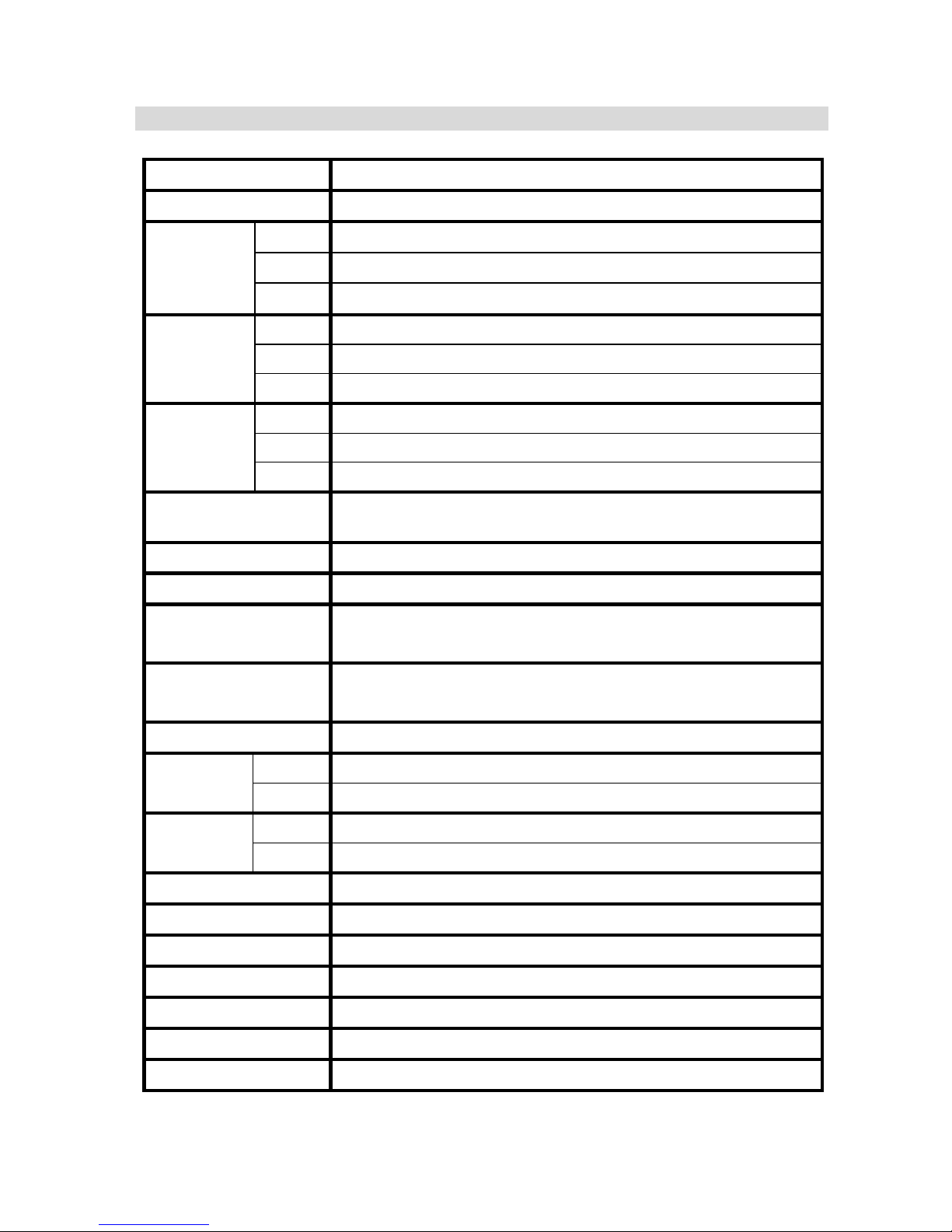
1. Specifications
Model CT-6300RS
Measuring modes Residual(Free) Chlorine / Ozone / Temperature
Cl2 0.00~100.00 ppm(mg/l), depends on sensor
O3 0.00~20.00 ppm(mg/l), depends on sensor
Ranges
TEMP -30.0~130.0°C
Cl2 0.01 ppm(mg/l)
O3 0.01 ppm(mg/l)
Resolutions
TEMP 0.1°C
Cl2 ±0.5%±1Digit
O3 ±0.5%±1Digit
Accuracy
TEMP ±0.2°C±1Digit
Temperature
Compensation
Automatic with PT-1000 / NTC-30K or manual adjustment
Ambient Temp. 0~50°C
Storage Temp. -10~70°C
Display
LCD display with sensitization sensor for
auto/manual illumination function
Analog output
Isolated DC 0/4~20mA corresponding to
residual chlorine/ ozone measurement, max. load 500Ω
Serial Interface RS-485(MODBUS RTU or ASCII)
Contact 240VAC, 0.5A Max. (recommend)
Settings
Activate Hi/Lo two limited programmable
Contact 240VAC, 0.5A Max. (recommend)
Wash
Time ON: 0∼9999 sec. / OFF: 0.0∼999.9 hours
Voltage output DC±8V , 0.5W Max.
Power Supply 100V~240VAC±10%, 5W Max., 50/60Hz
Installation Wall or Pipe or Panel Mounting
Dimensions 144 mm × 144 mm × 115 mm (H×W×D)
Cut off Dimensions 138 mm × 138 mm (H×W)
Weight 0.82Kg
Protection IP 65 (NEMX 4X)
Note: The specifications and appearance of the instrument are subject to change without notice.
1
Page 5
Wrong wiring will lead to breakdown or electrical shock of the instrument, please read this
operation manual clearly before installation.
z Make sure to remove AC power from the transmitter before wiring input, output connections,
and remove it before opening the transmitter housing.
z The installation site of the transmitter should be good in ventilation and avoid direct
sunshine.
z The material of signal cable should be special coaxial cable. Strongly recommend using our
coaxial cable. Do not use normal wires instead.
z Avoid electrical surge when using power. Especially when using three-phase power, use
ground wire correctly.
z The internal relay contact of the instruments is for alarm or control function. Due to
safety, please must connect to external relay which can stand enough ampere to make
sure the safety operation of the instruments. (Please refer to chapter 4.5“Illustration of
electrical connection”)
3. Assembly and installation
3.1 T ransmitter installation: This transmitter can be installed through panel mounting,
wall mounting and pipe mounting.
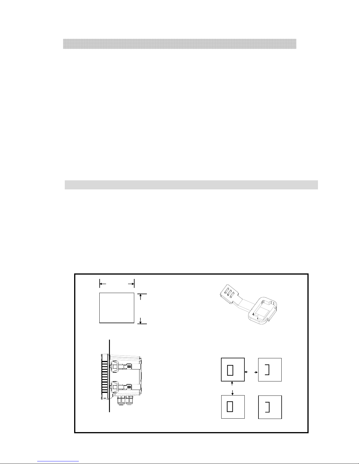
Installation of panel mounting: First, prepare a square hole of 138 x 138mm on the panel box,
and then insert the transmitter directly into the panel box. Insert the accessorial mounting
bracket from the rear, and make it be fixed in to pickup groove.
3.2 Illustration of panel mounting:
2. Precautions for installation
138mm
138mm
42mm
+
+
42mm
Hole distances on the panel box
Mounting bracket
Illustration of panel mounting,
fixed with Mounting bracket
+
+
2
Page 6
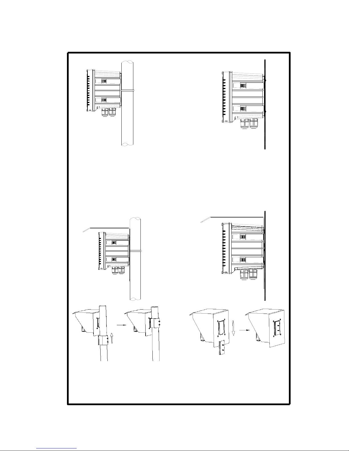
3.3 Illustration of Wall mounting and pipe mounting
Installation of pipe mounting
Fixed with U-shaped pipe clip
Order No.: 8-34
Installation of wall mounting
Fixed with 4 x M5 screws
Sun Shield (Pipe mounting)
Order No.: 8-35 and 8-35-1
Sun Shield (Wall mounting)
Order No.: 8-35 and 8-35-2
3
Page 7
4. Overview of residual chlorine/ozone transmitter CT-6300RS
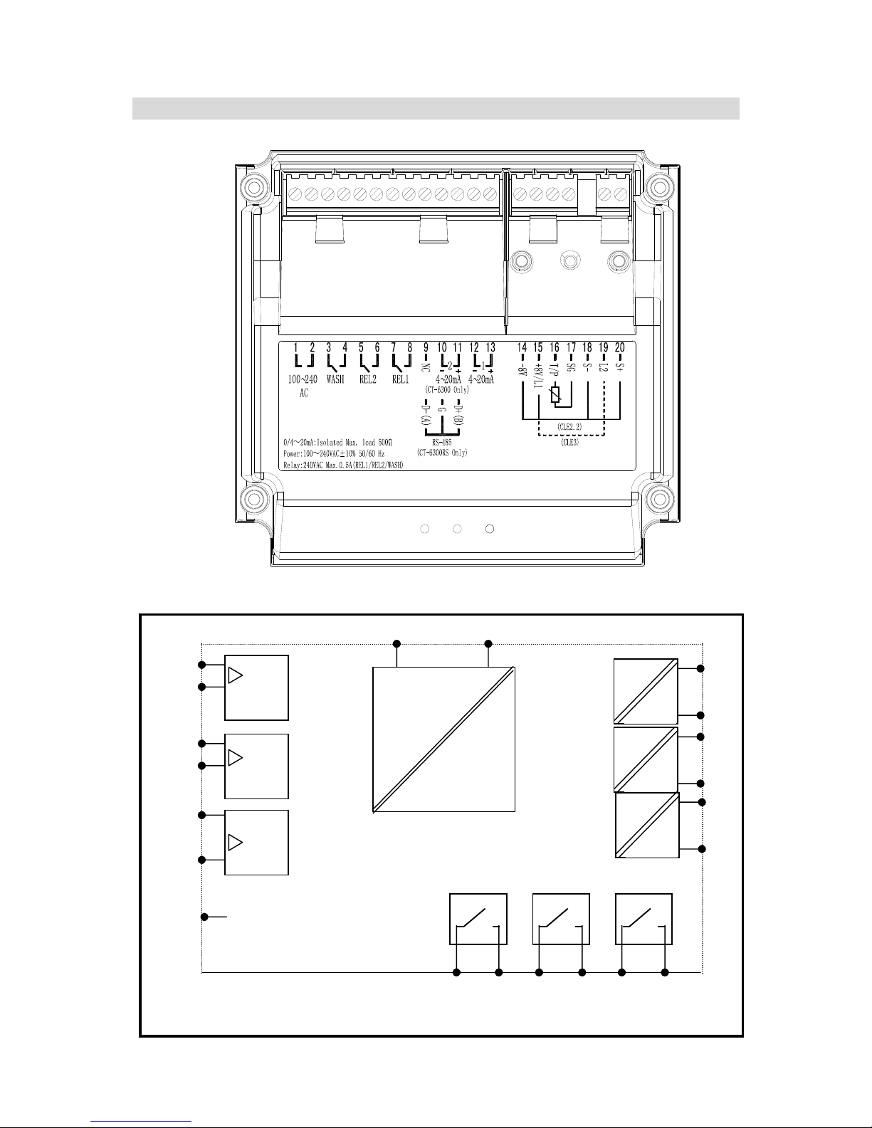
4.1 Illustration of rear panel
4.2 Illustration of terminal function
+
-
S+
S-
GND
TP
T
HI LO
WASH
POWER
AC
INPUT POWER
+
-
±8V
+
-
GND
Chlorine/O³
4 wire electrode (voltage type)
Chlorine/O³
2 wire electrode (current type)
L1
L2
4
Page 8
4.3 Description of terminal function
1
2
3
4
5
6
7
8
9
10
11
12
13
14
15
16
17
18
19
20
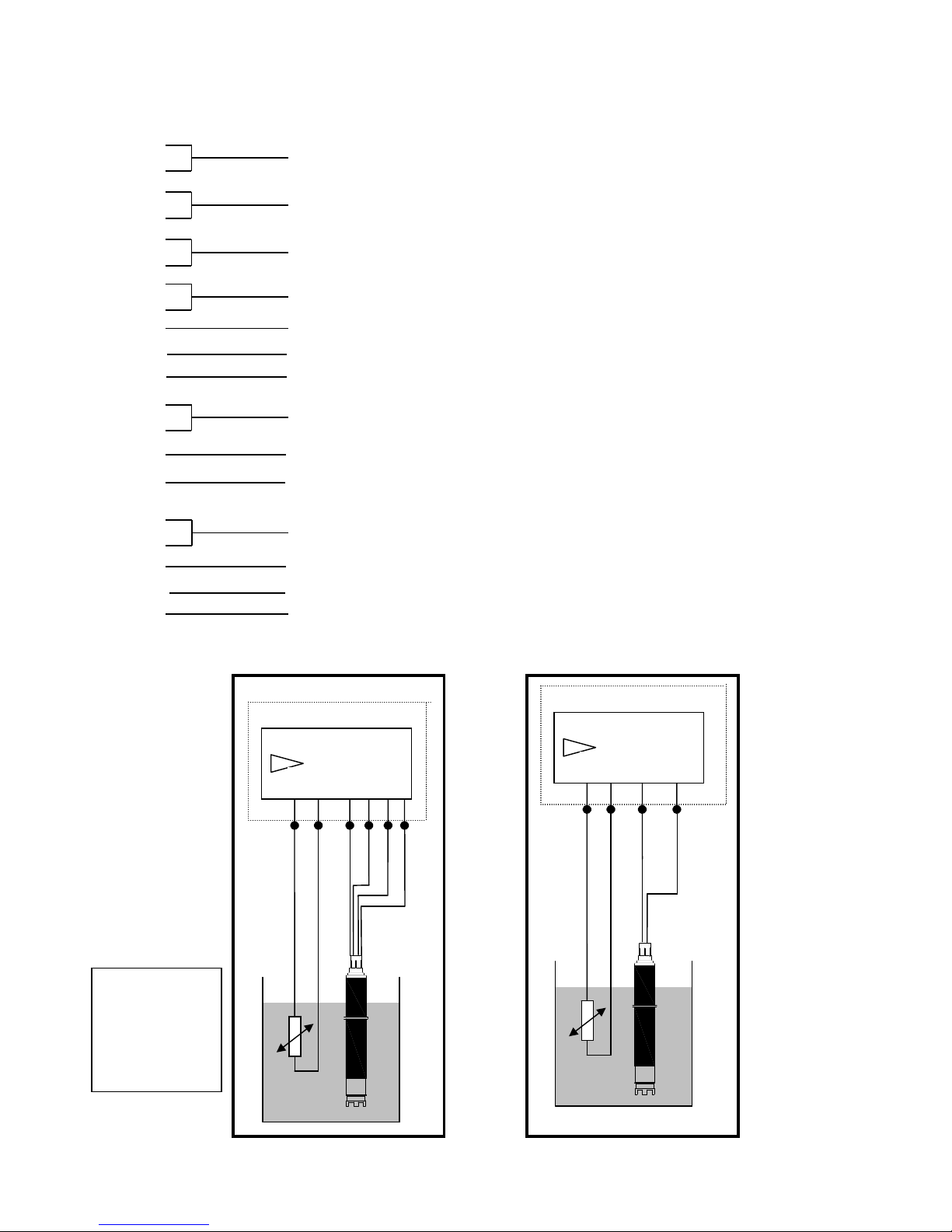
4.4 Illustration of cable wiring
Chlorine / O3
L2
2 wire electrode
(
current type
)
PT1000
N
TC30
K
T/P SG L1
1
2
Chlorine / O3
S+
4 wire electrode
(
voltage type
)
PT1000
N
TC30K
T/P
SG
S-
br
w
g
bl
+8 -8
AC100~240V: Power supply terminal
WASH: External wash relay terminal
REL2: External relay terminal Low Point control
REL1: External relay terminal High Point control
RS-485 output: GND
4~20mA:Master measurement current output terminal, for external
recorder or PLC control
DC-8V:Connect to voltage type electrode (CLE2.2) terminal V-(brown wire)
RS-485 output: D-(A)
T/P: Connect to earth end of temperature probe
DC+8V/ L1:Connect to a voltage type electrode (CLE2.2)terminal V+(green wire),
or connect to a current type electrode(CLE3, or OZE3) terminal 1.
S-: Connect to black signal wire of the voltage type of electrode (CLE2.2)
L2: Connect to terminal 2 of the current type electrode (CLE3, or OZE3)
S+: Connect to white signal wire of the voltage type of electrode (CLE2.2)
g: green wire
br: brown wire
bl: black wire
w: white wire
Wiring of 4 wire electrode
(voltage type)
Wiring of 2 wire electrode (current type),
leverage transmitter’s DC ±8V
14
15
RS-485 output: D+(B)
5
Page 9
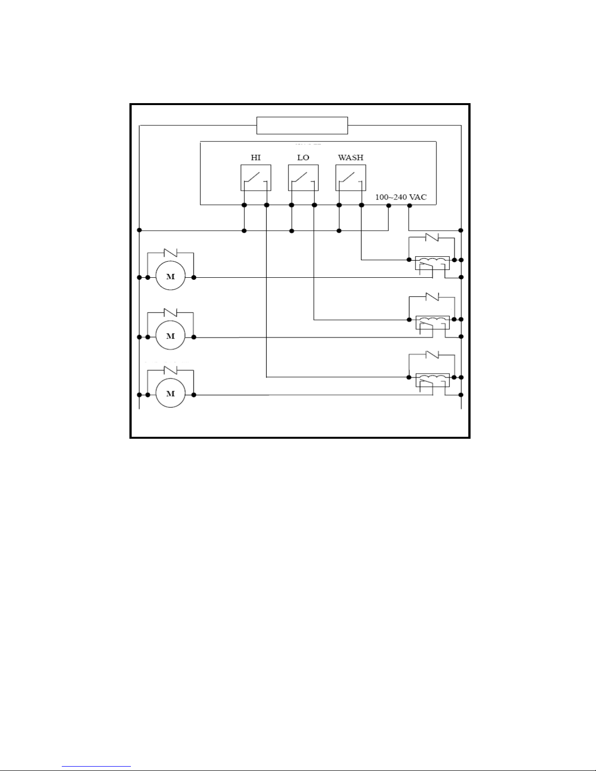
4.5 Illustration of electrical connection:
Surge absorber
Surge absorber
Surge absorber
Surge absorber
Transmitter
Cleaning device
Dose feeder
Dose feeder
100 ~ 240VAC
Surge absorber
Surge absorber
External relay
External relay
External relay
6
Page 10
5. Configuration:
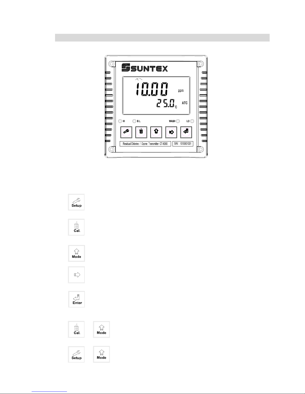
5.1 Illustration of front panel:
5.2 Keypad:
In order to prevent inappropriate operation by others, before the parameter setting and
calibration, the operation applies multi-keys, and coding protection if necessary.
Description of the key functions is in the following:
In the parameter set-up mode, pressing this key allows you exit parameter set-up
mode and back to Measurement mode.
In the Calibration mode, pressing this key allows you exit Calibration mode and
back to Measurement mode.
In the parameter set-up mode and Calibration mode, pressing this key to
increase the value or to scroll to other function.
In the parameter set-up mode and Calibration mode, pressing this key to
decrease the value or to scroll to other function.
: Key for confirmation; pressing this key is essential when modifying data value
or selecting the parameter setting items in the window.
: In the Measurement mode, pressing these two keys simultaneously
allows you enter Calibration mode.
: In the Measurement mode, pressing these two keys simultaneously
allows you enter parameter set-up mode.
+
+
Setup Cal. Mode Enter
7
Page 11
In the Measurement mode, press the two keys simultaneously for
five seconds, and then press until you see a clock signal appearing on the display;
then loose all keys to restore factory default settings.
In the Measurement mode, press the two keys simultaneously for
five seconds, and then press until you see a clock signal appearing on the display;
then loose all keys to restore factory default calibrations.
5.3 LED indicators:
WASH: Washing device operation indicator lamp; when the washing device is started up,
the Alarm indicator will light.
HI : Controlling operation indicator lamp; when the high setting point is reached, the
REL1 indicator will light.
LO : Controlling operation indicator lamp; when the low setting point is started up, the
REL2 indicator will light.
B.L. : Light sensor; in the automatic display backlit mode, the lamp will light or go out
as the change of environmental brightness.
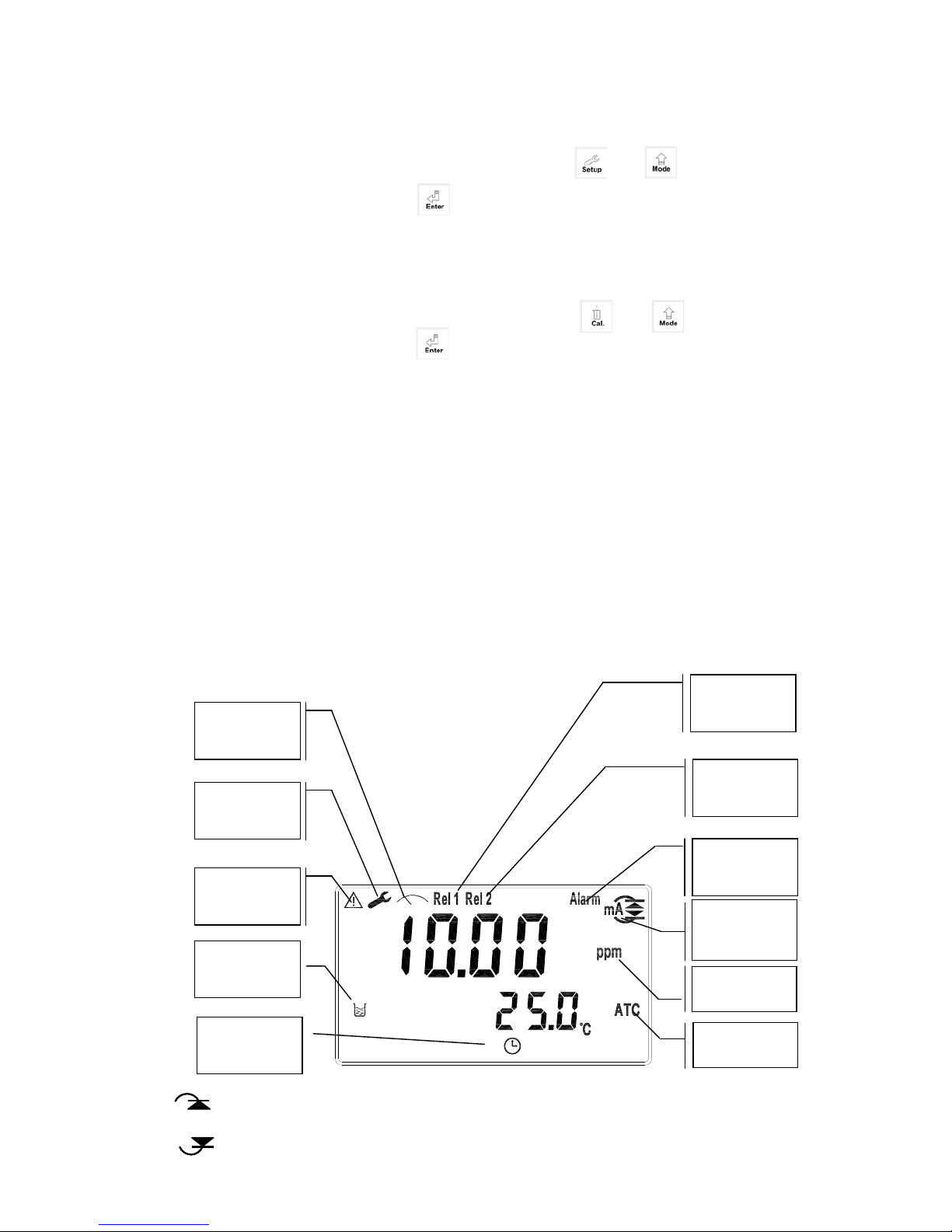
5.4 Display:
(Master Reset)Restore factory default parameter’s settings
+
+
(Calibration Reset)Restore factory default calibration’s settings
Calibration
mode
Controlling
function
locked
Set-up
mode
Measurement
mode
Relay 1
alarm
activated
Relay 2
alarm
ac
t
ivated
Clean device
activated
Output
current
Over ran
g
e
Measurement
uni
t
Recovery
indicator
mA
mA
: Measurement is over-range than the setting which is corresponding to output 20mA
: Measurement is over-range than the setting which is corresponding to output 0/4mA
Auto temp.
co
m
p
ensation
8
Page 12

6. Operation
6.1 Measurement mode:
After all electrical connections are finished and tested, connect the instrument to the
power supply and turn it on. The transmitter will automatically entering measurement
mode with the factory default settings or the last settings from user.
6.2 Set-up mode:
Please refer to the set-up instructions in Chapter 7, and press to back to
measurement mode.
6.3 Calibration mode:
Please refer to the calibration instruction in chapter 8, and press to back to
measurement mode.
6.4 Reset:
Factory default value:
Measurement mode: CLE2, 20.00 ppm
Temperature compensation: MTC
Auto return: AUTO
Relay 1(High point alarm):AUTO,SP1= 10.00 ppm,db1= 0.10 ppm
Relay 2(Low point alarm):AUTO,SP2= 1.00 ppm,db2= 0.10 ppm
Wash time: OFF(ON.S=0S,OFF.H=O.OH,DB.S=10S)
Analog output4~20 mA,0.0~20.00 ppm
Date & Time: 2010/1/1, 00:00:00
RS-485: RTU,Even,19200,ID:01
Code: OFF
9
Page 13

7. Settings
Block diagram of settings 1:
Parameter
Setting
Conf.
Setting)
Code
Setting
℃
Setting
(Temp.)
Relay 1
Setting
Cln
(Clean)
Setting
Cl/O3
Setting
(Analog)
Default
(密碼設定)
OFF
CodeONCode
Pass
code
change
Select
CL
(Chlorine)
OFF
(MTC
)
Input
Temp.
Temp.
Correct
(±5℃)
Imput
REL1
SP
Input
REL1
DB
REL1
Active or
Inactive
Relay1
Test
Cln
Off-time
Input
Cln
DB
Input
Cln
Test
Cln
On-time
Input
b.L.
Setting
(Backlight)
Pass code
Input
Active
Pass code
:Right forward key
:Up forward key
:ENTER key
Select
CLE2
Select
CLE3
PTC
REL1ONREL1
OFF
Relay2
Setting
Input
REL2
SP
Input
REL2
DB
REL2
Active or
Inactive
Relay2
Test
REL2ONREL2
OFF
Select
O3
(Ozone)
Select
O3E3
Std.b
(Auto
return)
OnAuto
Select
O3E2
ppm
or
mg/l
ppm
or
mg/l
ppm
or
mg/l
ppm
or
mg/l
Cln
Active or
Inactive
Cln ONCln
OFF
Range
2.00
Range
100.0
Range
20.00
Temo.
Correct
(±5℃)
NTC
Continued on next page Continued on next page
10
Page 14

Cl/O3
Setting
(An alog)
SEC
Settin g
(D ig ital
filter)
Re la tiv e
valu e to
20mA
0/4 and
20mA
Output Test
0/2 0mA o r
4/20mA
Output
Signal
average
: Right fo r ward k e y
: U p fo rw ard ke y
:EN TER key
Re la tiv e
valu e to
0 or 4mA
b.L.
Setting
(Backlight)
Select
Auto
mode
Select
ON
mode
OFF
Bright
-ness
setting
Bright
-ness
setting
Sensi-
tivity
setting
RTC
Settin g
(Tim e)
SERL
Set
(RS-485)
Input year
Select
comm unica
-tion mode
Input date
Select Odd
or Even
parity
Input time
Select
Baud rate
Set
ID
Cln
Settin g
(Clean)
Code
Setting
Connected with previous page Connected with previous page
Block diagram of settings 2:
11
Page 15

7.1 Entry of set-up mode
In the measurement mode, pressing the two keys simultaneously allows
you enter the parameter set-up mode. You can back to the measurement mode at any
time by pressing the key . The original code is 1111.
7.2 Security code of settings
In the set-up mode, you can set up the code by pressing the key , and confirm by
pressing the key .
+
Enter parameter selection set-up
Press for confirmation
Press for confirmation
Press or
Press for confirmation
When the first “0” of the digits 0000
sparkles, press upward key or rightward
key to input the code, and press ENTER
for confirmation. Then, continue
inputting the second digit, and by
analogy.
(If security code is
cancelled, you can enter
the set-up mode directly
without inputting the
password any more. You
can reset the security code
by pressing “Mode” key
by double pressing.)
Modify the code =>
If you input the wrong
code, the CODE will
sparkle 4 times, and
then the display will
back for another input.
12
Page 16

7.3 Measurement parameter set-up
Please select” CL” for residual chlorine measurement. Then, please select “CLE2” for
4-wire (voltage type) electrode; select “CLE3” for 2-wire(current type) electrode. Then,
according to sensor model, select measuring limit “2.00ppm, “20.00ppm”, or “100.0ppm.”
Please select” O3 ” for ozone measurement. Then, please select “O3E2” for 4-wire
(voltage type) electrode; or select “O3E3” for 2-wire(current type) electrode.
to select O3orCL
Enter “temperature” set-up
When select CLE3
When select O3E3, O3E2, CLE2
Press for confirmation
Press for confirmation
Press or
Press for confirmation
Press for confirmation
Press for confirmation
to select mg/l or ppm
Press or
to select 2.00, 20.00, or 100.0ppm
Press or
13
Page 17

7.4 Temperature parameter
7.5 Auto return set-up
Enter setup of auto return mode (Return) to set the function that the instrument
automatically exit the setup menu after a period of time without pressing any key.
Enter “Auto return” set-up
Enter “High point alarm” set-up
If select auto, the display
automatically exit the setting or
calibration mode and back to
measurement mode after a period
of time without pressing any key.
Same as left procedure
Use standard thermometer to test
the actual temperature of the
solution, and press or
to input the correct temperature
value.
If necessary, compare with the
actual temperature value tested by
standard thermometer. Press
or to input the modified
value.
Press for confirmation
press
or
for selection
press
or
for
selection
Press for confirmation
Press for confirmation
to select
Press or
If select on, it needs to exit
setting or calibration mode
manually
Press for confirmation
14
Page 18

7.6 Hi point
Set the TH (THRESHOLD) and DB (DEADBAND) of Hi (REL1). The range for TH is
0.00~20.00ppm(mg/l); while the range for DB is 0.00~3.00ppm(mg/l).
Enter “Low point alarm” set-up
Press or to
decide to activate REL1
or not.
Press or
to make REL1
terminal or lamp test
Choose “on”,
lamp “HI” will be
lighted up on for a
while
Press or to set an
appropriate hysteresis value
Press for confirmation
Press for confirmation
Press for confirmation
Press for confirmation
Press for
confirmation
Press for confirmation
Press or to set the
required alarm point
15
Page 19

7.7 Lo point
Set the TH (THRESHOLD) and DB (DEADBAND) of Lo (REL2). The range for TH is
0.00~20.00ppm(mg/l); while the range for DB is 0.00~3.00ppm(mg/l).
Enter “Auto clean time” set-up
Press or to
decide to activate REL2
or not.
Press or
to make REL2
terminal or lamp test
Choose “on”,
lamp “Lo” will be
lighted up on for a
while
Press or to set an
appropriate hysteresis value
Press for confirmation
Press for confirmation
Press for
confirmation
Press for confirmation
Press or to set the
required alarm point
Press for confirmation
Press for confirmation
16
Page 20

Press or
to make RELAY tes
t
Press or to set the current output
and relay hysteresis value ( unit: second)
7.8 Wash time
Set the automatic starting time and turn-off time of the washing function. If any value
is set to be 0, the instrument will automatically stop this function.
Enter “Analog output 1 (Chlorine /O3 )” set-up
Press or to set the turnoff
time of the washing function (unit: hour)
Choose “on”, lamp “WASH” will
be lighted up for a while
Press or to set the starting
of the washing function (unit: second)
Press for confirmation
Press for confirmation
Press for confirmation
Press for confirmation
Press for confirmation
Press or to
activate the auto clean
function or not
17
Page 21

7.9 Analog output 1(Chlorine /O3 )
The user can adjust the relative relationship between the Chlorine /O3 measurement
range and the output current according to actual situation, in order to improve the
recognition of current output.
.
Enter “Date/Time” set-up
Press for confirmation
Press or
to make stimulation
test for a current
output of 0, 4 and
20mA
Press or to set the relative upper limit of
measurement value of 20mA
Press or to
select current output
mode 0-20 or 4-20 mA
Press for confirmation
Press for confirmation
Press or to set the
relative lower limit of
measurement value of 0.0mA
Press or
to set the relative
lower limit of
measurement value
of 4.0mA
Press for confirmation
Press for confirmation
18
Page 22

7.10 Date/time set-up
Enter setup of Date/Time(real time clock). Set the “Year”, “Month”, “Date”, “Hour”,
and “Minute” time. The transmitter may keep the clock in operation even when
encountering power failure. Only when the inner battery is out of power, the clock
may stop operation. Then, please replace the 3V CR2025 Li battery inside the
transmitter.
Enter “RS-485” Set-up
Press for confirmation
Press for confirmation
Press or to set the year
Press for confirmation
Press to set month and day.
Press key for moving to next digit’s setting.
Press for confirmation
Use to set the time.
The key is for digital displacement.
19
Page 23

7.11 RS-485 set-up
Uses may according to your need to freely set the ID and transmissioin speed of
the serial output.
Enter “Average signal value” Set-up
Press to confirm it
Press to confirm it
Press to confirm it
Press to confirm it
Press to confirm it
Press or to
set the ID of this instrument
Press or to
set the transmission speed
(Even parity)
(None parity)
(Odd parity)
Press or to
select parity
or no parity
Press or to
select parity
or no parity
Press or to
select RTU or ASCII
transmission mode
20
Page 24

7.12 Average signal value set-up
You may set which number of measurement value to make an averaged value to increase
the stability of display value.
Enter “Backlight display” set-up
Press or to set the number of
measuring value for an averaged value
Press for confirmation
Press for confirmation
Press for confirmation
21
Page 25

7.13 Backlight settings
Use or to
select -2, -1, 0, 1, 2 five
backlit brightness levels
Back to security code of setting mode
Use or to
select -2, -1, 0, 1, 2 five
backlit brightness levels
Use or to select -2,
-1,0,1,2 five levels of sensitivity
of linear optical sensor
Press for confirmation
Press for confirmation
Press for confirmation
Press for confirmation
Press for confirmation
Press for confirmation
Press for confirmation
Use or to select automatic, manual or off.
22
Page 26

8. Calibration
Calibration
mode
Code
Set
SLP
Redy
Pass code
input
OFF
CodeONCode
Pass
code
change
OS
Redy
SLP
setting
Pass code
input
Active
pass code
OS
setting
:toward right key
:toward up key
:enter key
Block diagram of calibration
23
Page 27

8.1 Security code of calibration
8.1.1 Code authorization: There is a two level password protection design. The
authorization of settings password is prior to the authorization of calibration password.
Therefore, you can unlock the calibration code with your “settings password” (security
code of settings), or directly input with your calibration password (security code of
calibration).
8.1.2 Code set: In the measurement mode, press simultaneously to
access calibration mode. The default security code of calibration is “1100”.
Back to Calibration Mode
+
Modify your own
code by
Press for confirmation
Press for confirmation
When the first “0” of the digits 0000
sparkles, press upward key or
rightward key to input the code, and
press ENTER for confirmation.
Then, continue inputting the second
digit, and by analogy.
(If security code is
cancelled, you can enter
the set-up mode directly
without inputting the
password any longer.
You can re-enter into the
calibration code setting
display by pressing
“Mode” key twice)
If you input the
wrong code, the
CODE will sparkle
4 times and then
the display will
back for another
input.
Press for confirmation
Press for confirmation
24
Page 28

8.2 Calibration principle: You may decide if you need to make a zero-point(offset: “oS” in
the display) calibration. If not, you may directly make a slope calibration (“SLP “in the
display.
OZONE (O3) Residual chlorine(Cl))
Zero-point
calibration
1. Not necessary (zero point accuracy of
the sensor< ±0.05ppm)
2. If in need, use distilled water or pure
water which contains no ozone to
clean it, and then drain out the water,
make zero point calibration with the
sensor in air.
1. Not necessary (zero point accuracy of
the sensor< ±0.05ppm)
2. If in need, use distilled water or pure
water which contains no chlorine to
clean it, and then drain out the water,
make zero point calibration with the
sensor in air.
Slope
calibration
Use spectrophotometer with ozone
reagent to make a measurement value
bench mark, and compare it with the
online measurement.
Use residual chlorine reagent (DPD-1)
to make a measurement value bench
mark, and compare it with the online
measurement.
8.3 Current type sensor calibration mode (ex: Ozone sensor)
1. Press to enter into calibration mode. According to 同時按
鍵,即可進入校正程式,利用按 或 鍵可視需要
選擇零點 “OFFSET 校正(顯示 oS)"後按 鍵進行步驟 3 或選擇斜率“Slope
校正(顯示 SLP)" 後按 鍵進行步驟 4。
2. 在校正時可隨時按 鍵離開校正程式,回到測量狀態。
3. 按 或 鍵輸入使顯示值與水樣臭氧值相同
(如右圖1.00ppm),接著
按 鍵,斜率校正
完畢,並
自動跳出校正程式,回
到測量狀態。
2. Press at any time under calibration mode to go back to
measurement mode.
1. Press to enter into calibration mode. According to
your need, press or to select zero-point (offset)
(displayed as “ oS ”), press to proceed step 3, or select
“slope calibration”(displayed as “SLP”), and then press to
proceed step 4.
+
3. When selecting zero-point (offset) calibration, please make
zero-point calibration in air after cleaning the sensor with
distilled or pure water which do not contain with chlorine. Wait
for display value becoming stable, press or to
adjust the value until it becomes 0.00. Then, press .
After zero-point calibration, the procedure will automatically
lead to slope calibration (displayed as “SLP”). If you do not
need to make a slope calibration, press to leave the
calibration mode and back to measurement mode.
4. When selecting slope calibration, put sensor into flow-through
chamber, and make the sample go into the chamber at least 15
minutes until the display value becomes stable. Leverage
spectrophotometer measurement as a bench mark value to
compare and adjust with the online value.
25
Page 29

8.4 Voltage type sensor calibration mode (ex: residual
chlorine sensor)
5. Press or to make the display value as same as the
bench mark value (ex: right illustration: 1.00ppm). Then, press
to finish the slope calibration and automatically leave
calibration mode and return to the measurement mode.
2. Press at any time under calibration mode to go back to
measurement mode.
1. Press to enter into calibration mode. According to
your need, press or to select zero-point (offset)
(displayed as “ oS ”), press to proceed step 3, or select
“slope calibration”(displayed as “SLP”), and then press to
proceed step 4.
+
3. When selecting zero-point (offset) calibration, please make
zero-point calibration in air after cleaning the sensor with
distilled or pure water which do not contain with chlorine. Wait
for display value becoming stable, press or to
adjust the value until it becomes 0.00. Then, press .
After zero-point calibration, the procedure will automatically
lead to slope calibration (displayed as “SLP”). If you do not
need to make a slope calibration, press to leave the
calibration mode and back to measurement mode.
4. When selecting slope calibration, put sensor into flow-through
chamber, and make the sample go into the chamber at least 15
minutes until the display value becomes stable. Use residual
chlorine reagent (DPD-1) to make a measurement value bench
mark, and compare with the online measurement.
26
Page 30

8.5 Last Calibration Data
Back to“Calibration code"set-up
Press , if show
none, it represents no
calibration data.
Press to show year
of calibration data
Press to show date
of calibration data
Press to show time
of calibration data
Press to show
temperature record of
calibration data
Press to show OS(zero-point) value of
calibration data. If there was only SLOPE
calibration, there is no OS data.
Press to show SLP(SLOPE) value of
calibration data. If there was only OS
calibration, there is no SLP data.
Press to confirm it.
27
Page 31

8.6 Attention of sensor usage
1. The transmitter is suitable both for 4-wire (voltage type) sensor and 2-wire
(current type) sensor. (Note: “C” means residual chlorine sensor, “O”
represents ozone sensor.)
2. Ambient temperature: -5~50˚C (Auto temperature compensation, maximum
temperature changes: less than 0.3˚C/mins.)
3. Maximum pressure— 1bar.
4. Applied flow: less than 30 L/hr. If the flow is under 15% of recommended
speed, the measurement reaction can speed twice up.
5. Initialization time: the initialization time is about 1~3 hours. Reserved and
re-initialization for measurement needs about 0.5~2 hours. After changing
membrane or electrolyte, it needs about 0.5 hour for re-initialization. After
clean electrode, it needs about 1~3 hours for re-initialization. Immerse the
sensor into a stirred sample solution at least 15 minutes before each
measurement.
6. Ambient pH: the sample solution must be controlled within pH 5.5 ~
8.0(especially for residual chlorine sensor) , and it must be under a stable
pH condition.
7. Calibration cycle: the sensor is not necessary for zero-point calibration. Use
DPD-1 residual chlorine agent for slope calibration. If you need high accuracy
measurement, it is recommended for making slope calibration method
everyday.
8. Life of membrane: about one year, depends on sample solution.
9. Life of electrolyte: about 6~8 weeks, depends on sample solution.
10. Material-membrane cover: transparent PVC, electrode body: black PVC
Attention: The front white part of the sensor is membrane. Do not tear down
the membrane, or it may not measure any more.
28
Page 32

9. MODBUS protocol and instructions for CT-6300RS
9.1 Communication connection
The RS-485 communication port of the transmitter features with electronic
isolation protection, lightning protection, and to provide internal independent ground
solution. It is allowed to use normal twisted-pair (segregation double-stranded twisted
pair cable) cable connections. All devices are in contact with a double-stranded, and
then all together, and another line will be connected with all the negative contacts, and
the isolated shield wire must be connected to GND. When we talk about
communication in the laboratory, the stand-alone master-slave communication is
relatively simple. Hence, it is allowed to consider using the normal cable instead.
However, there should be strictly in accordance with the requirements of industrial
engineering construction. Wiring diagram is as follows:
Note:
1. The RS-485 interface of CT-6300RS transmitter has a protective earth terminal.
When communicate with the RS-485, there should use with solution ground to
eliminate risk of safety.
2. It is allowed to use a 120 ohm impedance matching resistors at terminal
equipment in the transmission lines (D +, D-) ends across to effectively reduce or
eliminate signal reflection.
3. Without repeaters, the RS-485 network can not exceed a maximum of 32 nodes.
The maximum communication transmission distance of RS-485 is up to 1200
meters.
4. When communication, all the equipments of the network should be maintained in
the same transfer mode, baud rate, parity consistent. And each of the device
address can not be the same, so as not to conflict resulted in the normal network
communications.
5. The Modbus command of the transmitter can only access 50 registers. If it
exceeds the length, then it returns abnormal message.
D+
GND Master
D-
R
CT-6300RS
ID: 01
CT-6300RS
ID: 02
Other
Modbus
equipment
.....
29
Page 33

9.2 MODBUS name and address table
Function Code:03H, 06, 10H Modbus response (setup parameter)
Logic
address
Item
Number
of Byte
Informati
on type
Description of
data transmission
Default value Note
0001H Equipment’s ID 2 USHORT 1-247 1
0002H
Transmitter
model
6 USHORT ASCII Code CT-6300RS
0: RTU
0005H
Communication
protocol
2 USHORT
1: ASCII
0
0: 2400
1: 4800
2: 9600
0006H
Serial
transmission
speed (Baud rate)
2 USHORT
3: 19200
3
0: None
1: Even
0007H Parity 2 USHORT
2: Odd
1
0008H USHORT Second
0009H USHORT Minute
000AH USHORT Hour
000BH USHORT Day
000CH USHORT Month
000DH
Real-time clock* 12
USHORT Year
2011-01-01,
00:00:00
000EH Code setting* 2 USHORT Code setting 1111
0: MTC
1: PTC
000FH
Temperature
mode*
2 USHORT
2: NTC
0
USHORT 0: OFF
0010H 2
USHORT 1: AUTO
0
0011H 2 USHORT ON.S: 0-9999 0 Second
0012H 4 USHORT OFF.H: 0-999.9 0 Hour
0014H
WASH relay*
2 USHORT DB.S: 0-9999 0 Second
0: OFF
0015H 2 USHORT
1: AUTO
1
0017H 4 FLOAT SP1 10.00ppm
0019H
Relay 1 *
4 FLOAT DB1 0.10ppm
Data
affected by
sign byte
30
Page 34

0: OFF
001BH 2 USHORT
1: AUTO
1
001DH 4 FLOAT SP2 1.00ppm
001FH
Relay 2 *
4 FLOAT DB2 0.10ppm
Data
affected by
sign byte
0: AUTO
1: ON
0021H 2 USHORT
2: OFF
2
SHORT 2: Highest bright
SHORT 1: high bright
SHORT 0: Standard
SHORT -1: Low bright
0022H
Backlight
Brightness *
2
SHORT -2: Lowest bright
0
SHORT
2: Highest
Sensitivity
SHORT
1: High
Sensitivity
SHORT 0: Standard
SHORT
-1: Low
Sensitivity
0023H
Backlight
Sensitivity*
2
SHORT
-2: Lowest
Sensitivity
0
0024H
Sample average
of measurements
(Digital Filter) *
2 USHORT 1-60 5
0025H-
0030H
Factory reserved
Note : The actions without * sign only support for function code 03H. The actions with * sign support
function code 03H, 06H, 10H. USHORT data range from 0 to 65535, SHORT data range from
-32768 to 32767. FLOAT is a 4 data bits IEEE 754 format float. The data range follows is the same.
31
Page 35

Function code: 03H Modbus response (measurement parameter)
Logic
address
Item
Number
of Byte
Informati
on type
Description of
data transmission
Default value Note
0031H
Number of
measurement
channels
2 USHORT
CT-6300RS only
has one channel
1
pH
ORP(mV)
uS/cm
mS/cm
MΩ-cm
ppt
ppm
mg/l
%
mA
˚C
NTU
FNU
0032H
Sign byte
6 CHAR
FTU
ASCII
code
0035H
Residual chlorine
/Ozone
measurement
4 FLOAT
Residual chlorine
/Ozone
measurement
Data
affected by
sign byte
0037H
Temperature
measurement
4 FLOAT
Temperature
measurement
0039H-
0050H
Factory reserved
Important: Usage address please refer to 03H Modbus response (measurement parameter)
Function code: 01H Modbus response (dispersion parameter)
Logic
address
Item BIT Description Default value Note
0070H LO Alarm 1 Contact on 0 (Contact off)
0071H Hi Alarm 1 Contact on 0 (Contact off)
0072H mA too high 1
Contact on 0 (Contact off)
0073H mA too low 1
Contact on 0 (Contact off)
0074H Exceed temp. range 1
Contact on 0 (Contact off)
0075H
Exceed Residual
chlorine /Ozone range
1
Contact on 0 (Contact off)
0076H RLY1 Action * 1 Contact on 0 (Contact off)
0077H RLY2 Action* 1 Contact on 0 (Contact off)
0078H WASH Action* 1 Contact on 0 (Contact off)
0079H Measurement status 1 Contact on 1 (Contact on)
0: Hold
1: Measurement
007AH-0
090H
Factory reserved
32
Page 36

9.3 Modbus example description(ex: function code 03H)
The following description takes the temperature reading(0037H) as an example. Set the
temperature at the transmitter at MTC 25.1oC, and confirm that host and sub-machine
communication format settings are correct. The host according to the following left table
to send commands, and then to get the response from sub-machine according to
following right table. This example shows the message transmission function code 03H
data format. If under other function code, the logic mode is the same.
ASCII Mode:
Request Response
Message Framing Hex Message Framing Hex
ID, Address 01 ID, Address 01
Function code 03 Function code 03
Starting Address Hi 00 Byte Count 04
Starting Address Lo 37 Register value Hi CC
No. of Registers Hi 00 Register value Lo CD
No. of Registers Lo 02 Register value Hi 41
LRC C3 Register value Lo C8
LRC 56
RTU Mode:
Request Response
Message Framing Hex Message Framing Hex
ID, Address 01 ID, Address 01
Function code 03 Function code 03
Starting Address Hi 00 Byte Count 04
Starting Address Lo 37 Register value Hi CC
No. of Registers Hi 00 Register value Lo CD
No. of Registers Lo 02 Register value Hi 41
CRC Check Lo 75 Register value Lo C8
CRC Check Hi C5 CRC Check Lo 65
CRC Check Hi 5A
Note: FLOAT is a 32-bit IEEE 754 format. The above table, for an example, is divided
into two 16-bit register data transmission. The back 16-bit register(CC CD) will be
transferred first, and then the first 16-bit register (41 C8) will be transferred later.
Every 16-bit format is high-bit in the front and low-bit in the post. For example, the
temperature now is 25.1oC. The 16-bit of FLOAT data(Hexadecimal) will show
41 C8 CC CD. The transmission order is CC CD 41 C8.
33
Page 37

10. Error messages (Error code)
Messages Reason Dispositions
Serious error that
does not permit any
further measuring
Please call service
engineer.
SLOPE value
exceeds the upper or
lower limit
Maintain the
electrode or change a
new electrode, and
make another
calibration.
OFFSET(zero-point
electric potential)
value exceeds the
upper or lower limit
Maintain the
electrode or replace
the electrode, and
make another
calibration.
34
Page 38

11. Maintenance
Generally speaking, under normal operation, the controller produced by our
company need no maintenance except regular cleaning and calibration of the
electrode to ensure accurate and stable measurement and system operation. When
the sensor cannot be calibrated or has too much error, please follow the instruction
below to maintain the sensor .
1. Please pull out the sensor from the flow-through chamber. Clean the sensor’s
membrane with tap water (low flow) to remove the contamination above the
sensor head.
2. Lightly rotate and remove the sensor’s membrane cover. Check whether the
upper and lower filter membranes of the sensor are broken or not. If yes, please
replace with a new membrane kit. If not, remove the coating material (ex: rust)
by immersing the sensor membrane into 5% HCL (for over a night).
3. Clean negative (silver) pole and positive (golden) pole:
Gently clean the negative pole and positive pole with clean water. If you
still find some contamination, take action by following instruction.
(1)Negative (silver) pole: You can gently rub the negative(silver) pole with
fingers. Do not use other tool to clean to prevent scraping.
(2)Positive (golden) pole: You can gently rub the positive (golden) pole with
fingers. However, if there is water stain on the golden pole, or if the
oxidation is difficult to clean, you may use micro-particle sandpaper to
gently rub the surface of positive (golden) pole.
4. After cleaning it, please make dry it by sun-shine, drain out the water inside by
fill in electrolyte.
5. Fill in the electrolyte into membrane cap until it is 80% full( do not contain any
bubble). Then, gently tight the cap up to the sensor. After tight up, reverse the
sensor to see if there is any bubble in side the membrane cap. (If yes, please
open the cap, and re-fill in the electrolyte. After the clean procedure, please
follow this operation manual to finish installation and calibration procedures.
35
Page 39

Page 40

SUNTEX INSTRUMENTS CO., LTD.
13F, No. 31, Lane 169, Kangning St.,
Xizhi Dist., New Taipei City, Taiwan (R. O.C.)
Tel: 886-2-2695-9688
Fax: 886-2-2695-9693
e-mail: suntex@ms1.hinet.net
www.suntex.com.tw/en
5040C CT-6300RS/Technical data subject to alternations/ Quality Systems ISO 9001/201206
 Loading...