

FA-HC30144
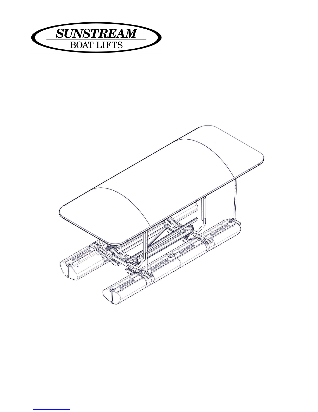
FL10, 13, 15 HOVERCOVER
ASSEMBLY , INSTALLATION & USE MANUAL
© SUNSTREAM CORPORATION 2010—ALL RIGHTS RESERVED
PART NO. 690178 REV: C
READ CAREFULLY
KEEP THESE INSTRUCTIONS

Table of Contents
Disclaimer of Liability
Parts List
Assembly
Height Adjustment
Safety Instructions/Maintenance
Warranty
3
4-5
6-19
20
21
22
Tools Recommended
Socket Wrench, 9/16” & 1/2” sockets
9/16” Wrench
1/2” Wrench
Drill
5/16” & 3/8’ Drill bits
3/8” Nut Driver
Screwdriver
Anti-seize
PART NO. 690178 REV: C 2

Disclaimer of Liability
These assembly and installation instructions have been provided by Sunstream Corporation at the
request of the potential installer and/or assembler. If you are not an authorized Sunstream Dealer
and are not a reasonably skilled mechanic, please contact Sunstream so that we can refer you to a
local dealer who can skillfully and safely perform the assembly and installation of your Sunstream
boat lift.
It is the potential installer and/or assembler’s responsibility to determine whether he or she has the
necessary skills, knowledge, and tools to properly and safely assemble and/or install the Sunstream
Lift described herein. Improper assembly and/or installation may cause the lift to function improperly or not to function. Improper assembly and/or installation may additionally cause a risk to
personal safety or property. If the assembler and/or installer is confused or has questions or concerns about a particular assembly or installation, he or she should contact Sunstream by telephone
at (253)-395-0500, Int’l (001)-(253)-395-0500 before proceeding further. The information contained in these instructions does not constitute a warranty or guarantee of any kind.
An assembler’s and/or installer’s failure to correctly follow these assembly and installation instructions constitutes a waiver of the assembler and/or installer’s rights against Sunstream regarding any subsequent damages to property or personal injury caused by the assembler’s and/or installer’s improper assembly and/or installation.
PART NO. 690178 REV: C 3
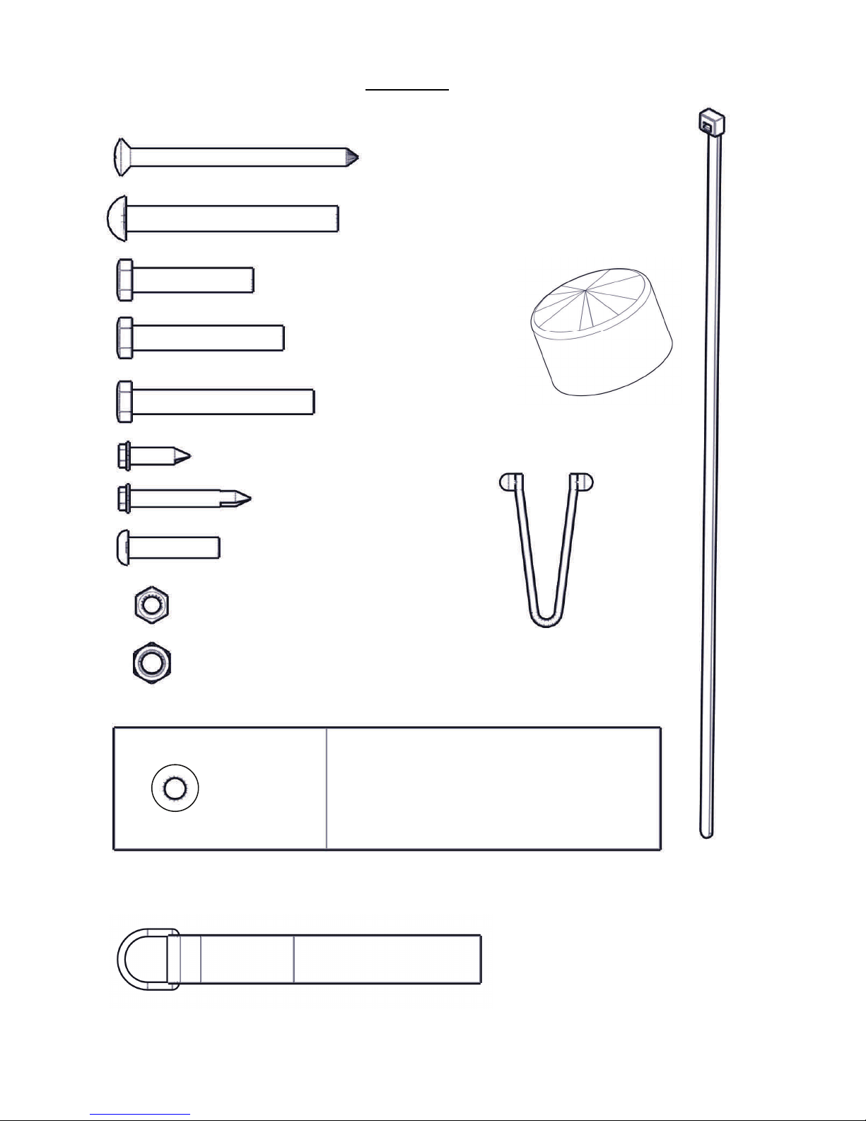
Parts List
16
34
4
4
16
25
8
12
SELF THREADING SCREW #14 X 4.00”
MACHINE SCREW 5/16” X 3.50”
11-051401-90
BOLT, 3/8” X 2.00”
11-060801-32
BOLT, 3/8” X 2.50”
11-061001-92
BOLT, 3/8” X 3.00”
11-061200-16
SELF DRILLING SCREW #14 X 1.00”
11-000401-93
SELF DRILLING SCREW #14 X 2.00”
11-000001-81
BOLT, 5/16” X 1.50”
11-050600-38
11-041602-40
4
CAP
690501
17
WIRE TIE
690255
55
28
10
16
NYLOCK, 5/16”
12-050000-62
NYLOCK, 3/8”
12-060000-22
VELCRO STRAP
69-000001-00
D-RING VELCRO STRAP
690493
6
SNAP BUTTON
15-000001-83
RAFTERS
PART NO. 690178 REV: C 4
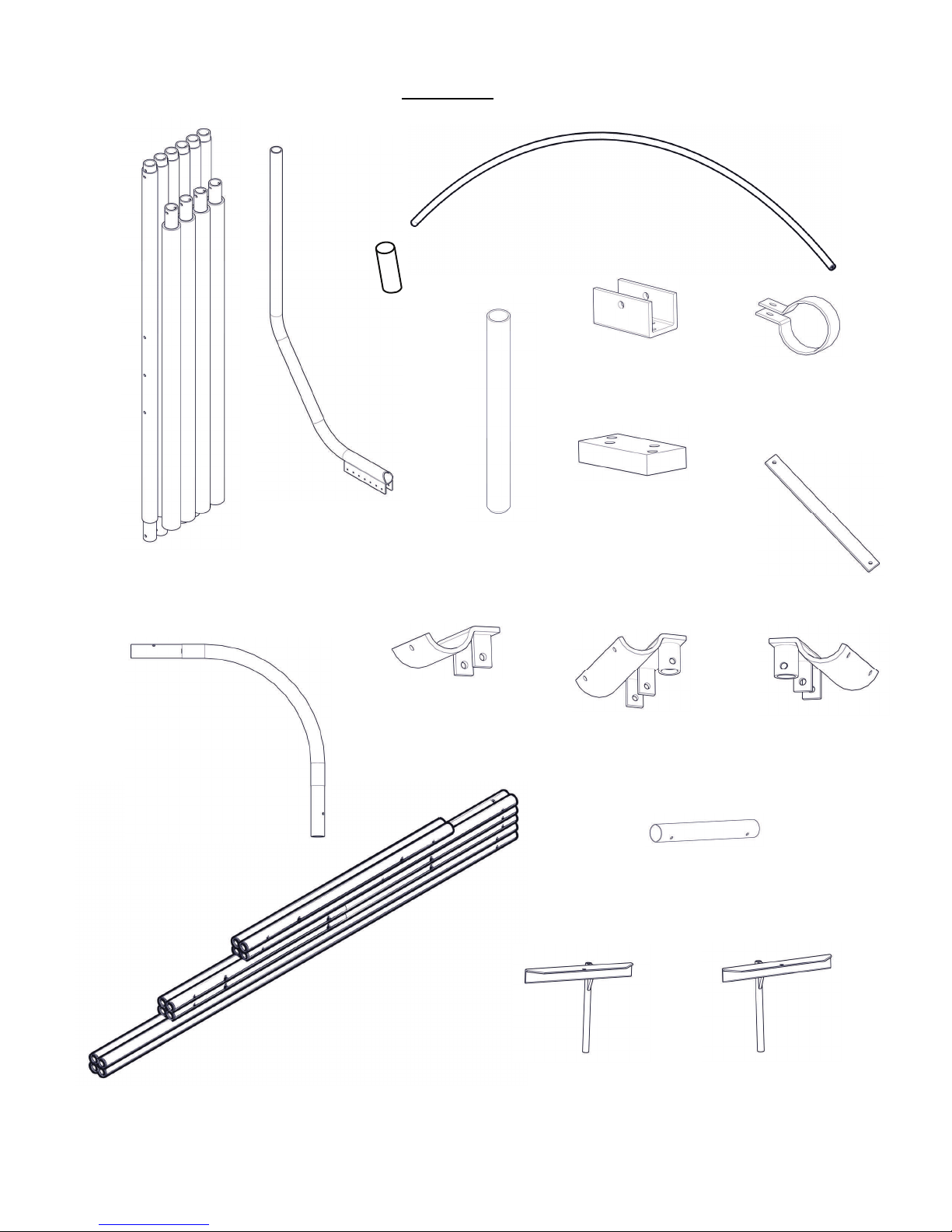
Parts List
8
RAFTER
941624
4
1
UPRIGHT AS.
94-000009-30
4
PVC ELBOW
44-000011-69
STOP TUBE
440627
2
GUIDE ON
95-000006-19
GUIDE ON SLEEVE
44-000008-99
2
END BRACKET
95-000008-85
2
6
FLOAT BRACKET
44-000011-56
2
SHIM
42-000012-72
2
FRAME BRACKET L
95-000007-92
12
CLAMP
42-000012-73
6
DIAGONAL BAR
44-000012-66
2
FRAME BRACKET R
95-000007-93
1
FRAME TUBE AS.
95-000009-27
BAG 1
1
OWNERS MANUAL 690178
1
PART NO. 690178 REV: C 5
1
END FLOAT BRACKET L
95-000008-87
6
UNION SLEEVE
44-000011-72
1
END FLOAT BRACKET R
95-000008-86
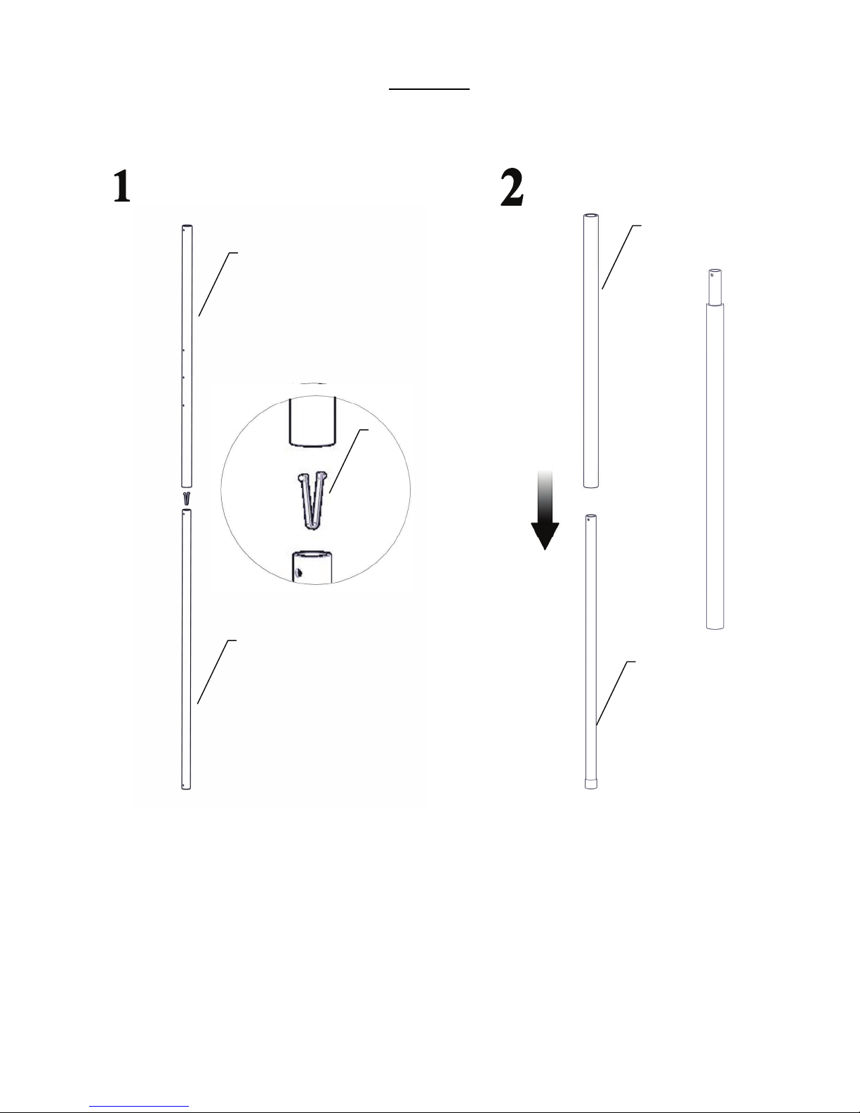
Assembly
Assemble all Telescoping Linkages Assemble all Slide Tubes
Outer PVC Guide
Outer Telescoping Linkage
Snap Button
Inner Telescoping Linkage
Note orientation
Inner Aluminum Guide
PART NO. 690178 REV: C 6
PVC Guide
Assemble all Uprights
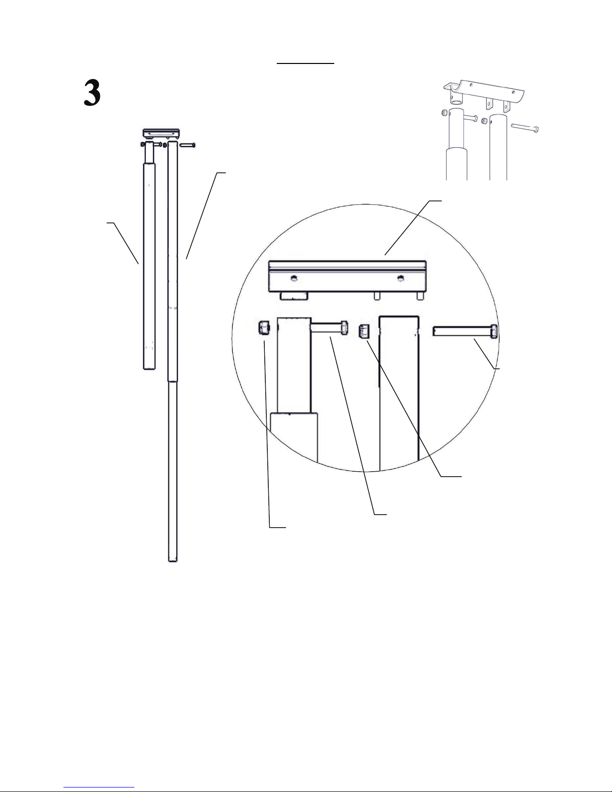
Assembly
Telescoping
Linkage
Frame Bracket
Bolt, 3/8” x 3.00”
Nylock 3/8”
Bolt, 3/8” x 2.50”
Nylock 3/8”
IMPORTANT:
Do not over tighten bolt. Squeezing the frame bracket prevents Linkage from pivoting.
PART NO. 690178 REV: C 7

Assemble Frame
End Tube
Assembly
End Tube
5/16” X 3.50”
MACHINE SCREW
18X
Side Tube
Ensure all Velcro Strap hooks & loops face to inside of frame.
6 ft Center Tube
7”
NYLOCK, 3/8”
VELCRO STRAP
18X
10X
5”
PVC Elbow
PART NO. 690178 REV: C 8
Union Sleeve
Note rafter hole orientation
IMPORTANT:
Ensure Side Tube dimensions are as follows:
Holes 5” from end connect to PVC Elbow.
Holes 7” from end connect to Union Sleeve.

Secure rafters.
Assembly
#14 x 4.00”
Self Threading Screw
16X
D-Ring Velcro Strap
16X
Ensure all Velcro Strap hooks & loops face to inside of frame.
PART NO. 690178 REV: C 9

Assembly
Remove Guide-on caps from existing guide-ons.
Install additional guide-ons and drop stop tubes down guide-ons.
Guide-on Sleeve
2X
Stop tubes
Bolt 3/8” X 3.00”
Nylock 3/8”
6X
Set guide-ons to desired boat beam width.
Install End Float Brackets
4X
PART NO. 690178 REV: C 10
End Float
Bracket L
FWD
End Float
Bracket R
End Float Bracket L
2X

Assembly
Align Telescoping Linkages with Guide-ons.
Position Float Bracket an attach with Self Drilling Screws. If a 3/8” Nut Driver is not available,
drill a 3/16” hole and install with 3/8” socket wrench. Dimension reflects approximate location.
PART NO. 690178 REV: C 11
Self Drilling Screw
#14 X 1.00”
Float Bracket
9”
16X

Attach telescoping Linkages.
Assembly
Self Drilling
8X
Screw
Float Bracket
Shim
8.5”
Position Float Bracket and attach Self Drilling Screws through shim and secure into end float
brackets. Shim can be pre-drilled prior to securing. Dimension reflects approximate location.
PART NO. 690178 REV: C 12

Assembly
Align Telescoping Linkages with Guide-ons.
4X
Nylock 3/8”
Bolt, 3/8” X 3.00”
2X
Nylock 3/8”
Bolt, 3/8” X 3.00”
IMPORTANT:
Do not over tighten bolt. Squeezing the float bracket prevents Linkage from pivoting.
PART NO. 690178 REV: C 13

Assembly
Assemble and set Frame Attachment Tubes.
4X
Insert caps on end of tubes.
IMPORTANT:
Set Adjustable Frame Attachment Tubes on Frame Brackets and position to desired location.
PART NO. 690178 REV: C 14
Nylock, 5/16”
Bolt, 5/16” X 3.50”

Continued
Assembly
Adjustable Frame Attachment Tube.
1
NOTE: Use wire ties to temporarily hold frame
while assembling.
”
5
2
.
7
PART NO. 690178 REV: C 15


Secure Frame.
Assembly
Frame Assembly
Clamp
Adjustable Frame
Attachment Tube.
Nylock, 5/16”
Bolt, 5/16” X 1½”
IMPORTANT:
Set Hovercover Frame Assembly on Adjustable Frame Attachment Tubes and adjust Frame
Assembly to desired location over craft. Attach Frame using Clamps and fasteners.
PART NO. 690178 REV: C 17

10X
Assembly
Nylock, 5/16”
Frame Bracket
Drill using Frame Brackets as a template and attach fasteners.
Repeat for all brackets including forward brackets.
Bolt, 5/16” X 3.50”
PART NO. 690178 REV: C 18

Secure Cover, tighten Velcro
Assembly
1. Lay fabric over Frame.
2. Pull the corner pockets over the Frame Elbows & leave the split corner for later.
3. Pull split corner over Elbows. Pull long side of fabric over frame and then pull the
split corner over Elbow last.
4. IMPORTANT - Pull Velcro straps through drawstring but do not secure Velcro yet.
5. Tighten drawstring TIGHTLY and tie rings together.
CAUTION:
Tighten drawstring prior to securing Velcro. Water may pool in corners if cover is
improperly secured.
PART NO. 690178 REV: C 19

Height Adjustment
FL10 Hovercover clearances with lift up and down.
Height of the Hovercover is adjusted with the Telescoping Linkages.
The Hovercover has four preset positions incrementing every six inches. The height clearances for the Hovercover are:
1. With the lift in the up position, the distance between the bottom of the boat and the
bottom of the Hovercover frame.
2. With the lift in the down position, the distance between the surface of the water to
the bottom of the Hovercover frame.
The Hovercover can be set to the following range of heights .
Minimum
Height
Maximum
Height
NOTE:
Maximum and Minimum Heights are calculated from boat models with a 21° deadrise hull.
Maximum Boat Height assumes curved windshield. Actual height will be determined
by shape of boat.
Lift
Up
72”
84”
Lift
Down
97”
109”
Maximum
Boat Height
-
103”
Lift
Up
PART NO. 690178 REV: C 20
Lift
Down

Safety Instructions
If you have any questions, please call your dealer, or Sunstream at (253-395-0500).
Save These Instructions
Your safety and the safety of others is very important. Proper use of the information in this manual will help avoid
potential hazards that could cause damage to property and/or personal injury. It is not possible, however, to identify
and warn users of all hazards associated with the assembly, installation, operation, and maintenance of the Float Lift.
You must use your own good judgment.
Failure to comply with the following rules may result in severe injury and/or death and damage to
property.
1. Refer to your FloatLift™ owner’s manual to review safety specifications for your FloatLift.
2. The Hovercover moves from a raised position to a lowered position relative to your boat. In the low-
3. Be sure the Hovercover's height range is properly adjusted for your watercraft to avoid damage to
4. Avoid putting your hands or other body parts on the Hovercover's moving parts while the Hovercover
5. Be aware of environmental forces while using the Hovercover. Strong winds may cause the cover to
6. The Hovercover is a lightweight structure that is NOT designed to hold body weight. DO NOT hang
ered position, the Hovercover is meant to provide a close fit to your watercraft. Be aware of people in
the boat and the risk of the Hovercover contacting them.
boat windshields or other high reaching fixtures.
operates. Do not let children or others contact the Hovercover's moving parts while it operates.
become unstable. Excessive wave action may cause the cause the cover to become unstable. Remove
the fabric cover in the case of predicted extreme weather.
from the Hovercover.
Maintenance
1. Sunstream recommends an annual inspection by your Sunstream dealer.
2. Refer to your FloatLift™ owner’s manual to review maintenance requirements for your FloatLift.
3. Check telescoping PVC guides for binding and add light lubrication as needed. If binding continues, wrap duct tape around base of outer PVC Guide.
4. Check Velcro connections from time to time to ensure a continued tight fit.
5. Report evidence of excessive wear and tear to your Sunstream dealer or to Sunstream.
6. Remove canopy cover before snowfall.
7. Remove canopy cover if winds exceed 30 mph for a prolonged period of time.
Do not allow water to collect on the canopy fabric. Re-tighten tightening cords and/or adjust rafters
8.
to avoid such water collection.
Remove your canopy top for off-season storage or if boat is not on lift for an extended period of
9.
time.
Tighten nuts and bolts as needed.
10.
PART NO. 690178 REV: C 21

Standard Warranty
WARRANTY: Sunstream Corporation (“Company”) warrants its Products for non-commercial and/or non-governmental use for
a period of three (3)* years, in both fresh and salt water, to the original Purchaser (“Purchaser”) against manufacturing defects in all
Product materials and workmanship beginning from date of purchase of the Product from Company** under the following terms and
conditions:
NOTICE REQUIREMENTS AND REMEDIES
: If the Purchaser discovers a defect, the Company, or its authorized Company
dealer or agent, will, at the Company’s option: (1) repair the Product, (2) replace the defective part, or (3) refund the purchase price of
the Product upon confirmation by Company that the Product is defective, provided that the Company receives notice
of the defect from
the Purchaser or Company dealer before the warranty period lapses. Product changes caused by age or environment (such as marine
growth or heat) shall not constitute a defect. Confirmation of the defect shall require that reasonable proof of the defect be provided by
Purchaser to Company or Company dealer, and may include that the Product or part be returned to Company for inspection at
Purchaser’s initial expense. This warranty shall not apply if Company receives notification after the before-stated deadline, regardless
of when the defect occurred or was discovered, and regardless of the reason for the delay in notification. “Notification” shall be deemed
to have occurred when the Purchaser or Company dealer sends written notice to Company by fax or by e-mail and when receipt is
confirmed by Company’s response.
EXCLUSIONS
: This warranty does not apply to damages caused by or due to: (1) accident (including, without limitation,
collision, fire, flood, wind, ice or any other natural disaster or acts of God), abuse, misuse, overloading, out of level or improper boat
loading (i.e.: not fully on, too far on, or crooked on lift), or (2) faulty assembly or installation if such assembly or installation was not
performed by a Company employee or Company dealer. Company is not responsible for determining the weight or dimensions of
Purchaser’s boat, and Purchaser is advised that published boat specifications are often inaccurate. This warranty is void if the Product
has been modified without the permission of the Company or if any Company serial number has been removed or defaced. Normal
maintenance requires an annual inspection of the Product by a Company employee or Company dealer, including bolts, pins, hydraulics,
pump, electronics, and welds and failure to undertake such maintenance may constitute “abuse.” Lift components’ fluid level and
condition, including battery water and acid, SunFluid and strainer cleaning are maintenance items and are not covered by this warranty.
Zincs, ropes, batteries, cosmetic concerns and custom coatings are not covered by this warranty. Batteries supplied by Company that are
maintained in top operating condition by Purchaser are warranted for a period of one (1) year. Underwater light systems and the
DockJock are not warranted for use in brackish or salt water. This warranty does not void or alter any rights the Purchaser may have
against dealers or suppliers of component parts.
SALT WATER REQUIREMENTS AND EXCLUSIONS
maintenance requires that the Purchaser shall attach to the product, maintain and regularly check sacrificial anodes, also known as
prevent electrolysis from damaging the lift metals, and that failure to attach and maintain the zincs constitutes “abuse.” *** Underwater light systems
and the Dock Jock™ personal watercraft lifts are not warranted for brackish or salt water use regardless of zinc use.*
IN
TERNATIONAL WARRANTY
Canada, replacement parts shall be shipped with the dealer’s next containe
product if possible to expedite response. Purchaser has the option to pay for expedited freight if desired.
LIM
ITATIONS
furnished under this Agreement. Seller disclaims any implied warranty of merchantability or fitness for a particular purpose. Th
liability of any kind shall be limited to the remedies provided in
consequential damages or loss of use, revenue or profit. State law may override the above exceptions or limitations.
: Except as expressly stated herein, there are no warranties, expressed or implied, by operation of law or otherwise, of the Product
: The Purchaser agrees that if the Product leaves the borders of the United States of America, Puerto Rico or
: If any Company Product is used in brackish or salt water, the Purchaser agrees that proper
“zincs,” in order to
r order. International dealers have the option of using parts from stocked
e sole remedy for
this warranty and shall in no event include any incidental, indirect, special or
*Fresh water applications for underwater light systems and the Dock Jock™ winch and strap are warranted for one (1) year; salt water
applications are not warranted for these Products.
**If the Product is purchased from a Company dealer, the warranty term begins upon the date the Product is sold to the end Purchaser
or three (3) months from the date the Product is shipped from Company, whichever occurs first.
***Under normal conditions, zincs should last at least one (1) year. If Purchaser observes that the zincs are deteriorating in a shorter
time period, an external current could be entering the system and the Purchaser must find the source of this current and stop
it, or change zincs more frequently.
Sunstream Corporation
22149 68th Avenue South
Kent, WA 98032
USA
Web Site: www.sunstreamcorp.com
Phone: 1-253-395-0500 Fax. 1-253-395-0501
001-253-395-0500 (Int’l) 001-253-395-0501 (Int’l)
E-mail: warranty@sunstreamcorp.com
PART NO. 690178 REV: C 22
 Loading...