


Read all instructions before you install cabinet. Very
important to follow each step in order as detailed in this
Instruction Guide!!!
BASE & WALL
WALL CABINET INDEX
Parts Diagram ---------------2
Measurements --------------3
Lower Support Rails -------4
Upper Support Rails -------5
Positioning Cabinets -------6
Cabinet Details --------------7
Securing Cabinets ----------8
BASE CABINET INDEX
Grill Cabinet Trim-Kits --------------9
Grill Cabinet Trim-Kit Setup-------10
Grill Cabinet Support Rail----------11
Counter Rails & Side Panels -----12
Island Layout & Setup Guide -----13
Island Completion Overview ------14
WARRANTY -----------15
CABINET
SETUP GUIDE
BY SUNSTONE®
To installer or person assembling Cabinet Island: Leave this manual with cabinet for future reference.
To Consumer: Keep this manual for future reference.
www.sunstonemetalproducts.com
Page 2
1. WALL CABINETS – PARTS DIAGRAM
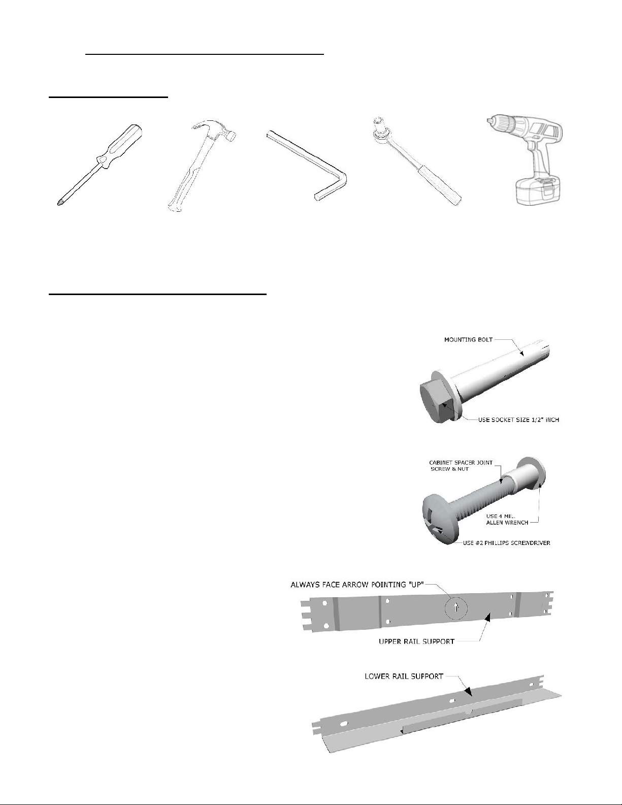
REQUIRED TOOLS
INCLUDED HARDWARE & PARTS
Each Wall Cabinet includes multiple Anchor Mounting
Bolts. Anchor Mounting Bolts are adaptable with any ½”
Socket Wrench. The Load Capacity per bolt is approximate
200 Pounds, even so we still recommend one bolt for every
available hole in support rails.
Unlike the lower base cabinets which use Pin-Lock’s to
secure in place next to one another, the Upper Wall
Cabinets use a combination #2 Phillips Screw and 4 Mil.
Nut Cap. The two end are inserted in through
corresponding holes on the interior of cabinets meeting
each other, at the top/middle/bottom positions.
Each Wall Cabinet includes multiple
Anchor Mounting Bolts. Anchor
Mounting Bolts are adaptable with
any ½” Socket Wrench.
#2 PHILLIPS
SCREW DRIVER
HOUSEHOLD
HAMMER
4 MIL. ALLEN
WRENCH
ELECTRIC
HAMMER DRILL
SOCKET WRENCH
W/ ½” SOCKET

Page 3
Know your Wall Type, these cabinets require support mounts to be Bolted into either Wood
Framing, or preferably into Masonry Stone. If installing to Exterior of Home Wall, if finding
wall studs are difficult – we recommend using ½” Plywood Board Insulator against Wall
where Wall Cabinets will be mounted to. This way the Heavy Weight of the cabinets is
evenly spread out across the wall and the Support Rail screw holes do not necessarily have
to line up with interior wall studs.
Important to get Accurate Dimensions placed, marking
up to the exact heights of true counter, to the height of
wall cabinets. In this instruction guide, we show
placing wall cabinets up 18” Inches above Frame or
Cabinet top edge without counter, which gives
adequate clearance, but depending on several factors
this dimension may change depending on how you
will be accessing the wall cabinets, or even how tall
you are plays an important aspect for what will be the
comfortable reachable height of any wall cabinets.
See the above illustration, detailing correct Dimensions for Base Frame or Cabinet Height,
Counter Top Edge, Base of Wall Cabinet Rail Support and the Top Edge line of Wall
Cabinet Upper Rail Support. Make sure to draw similar horizontal lines reflecting how it is
shown in this illustration matching to the dimensions shown.
2.WALL CABINETS – MEASUREMENTS
Page 4
Once all your Lines are drawn, next begin placing the individual wall cabinet support rails,
start with the bottom rail first. If your Wall Cabinet group is in a corner location, like shown
in this guide, then start in the Corner reaching out to the Left and Right cabinet runs. Or for
any straight Wall Cabinet Group, start either at the Left or Right side, whichever side is
against any wall structure first.
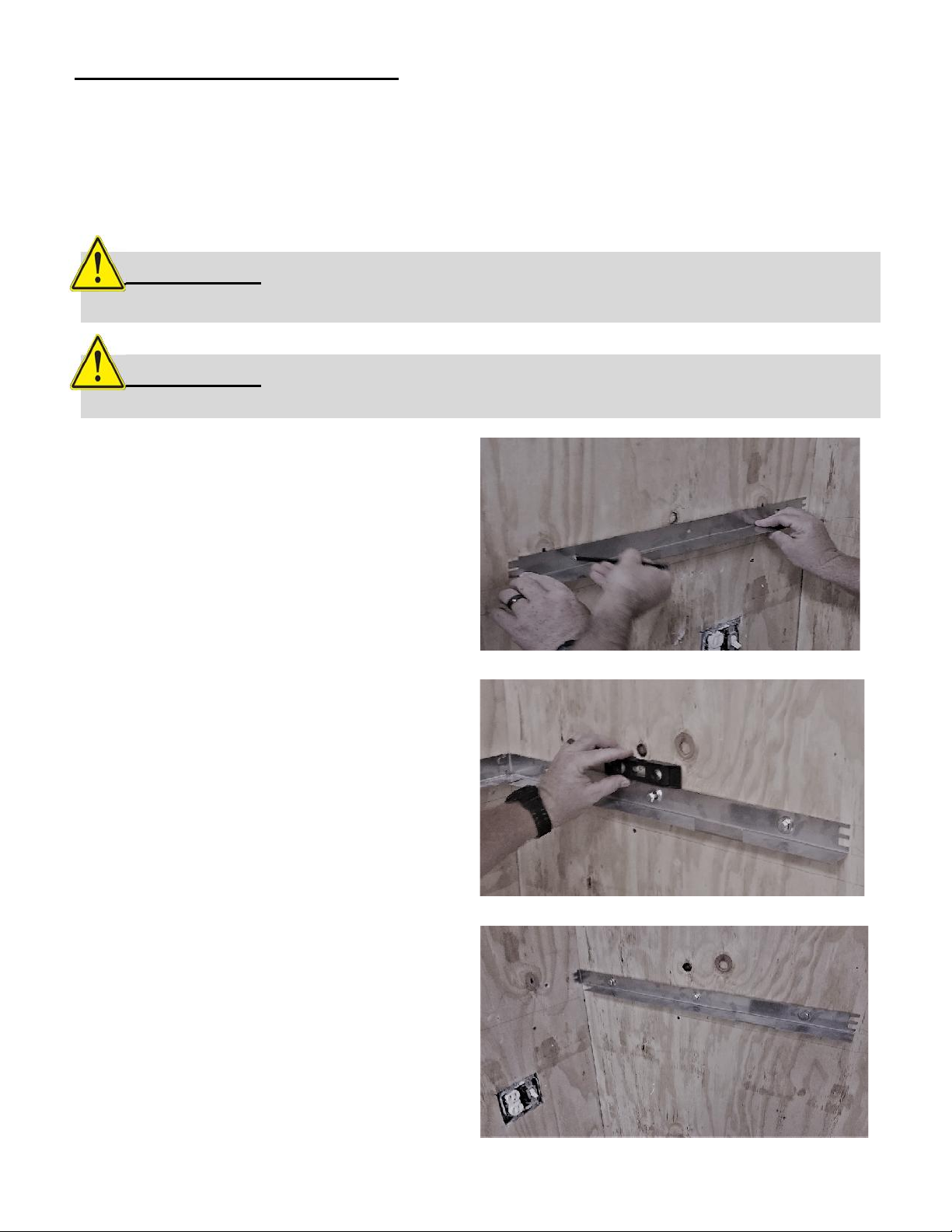
A. Hold each Bottom Rail against wall,
with underside edge on top of premarked lower horizontal line. Using a
pencil mark the corresponding drill
hole positions. Place Lower Support
Rail to the side, and using 3/8” Inch
Drill Bit, drill each marked hole.
B. Place the Base Horizontal Rail against
wall aligned to Pre-Drilled Holes, insert
the Mounting Bolts through each
corresponding hole. Use “Leveler” to
check support rail is Leveled as you
continue to Hammer each bolt into place.
C. Once Support Rail is affixed to wall,
with All Mounting Bolts in all the way,
now use Socket Wrench with ½”
Socket, and securely fasten in each bolt
at tight as possible.
ATTENTION: For exterior walls with Wood Framed Studs, you may need to
use “Lag Bolts” to properly secure Support Rails to wall.
ATTENTION: Be sure to use Mounting Bolt in each hole along Bottom
Support Rail, as it is the Base that supports the majority of the weight.
3.WALL CABINETS – LOWER
SUPPORT RAILS
Page 5
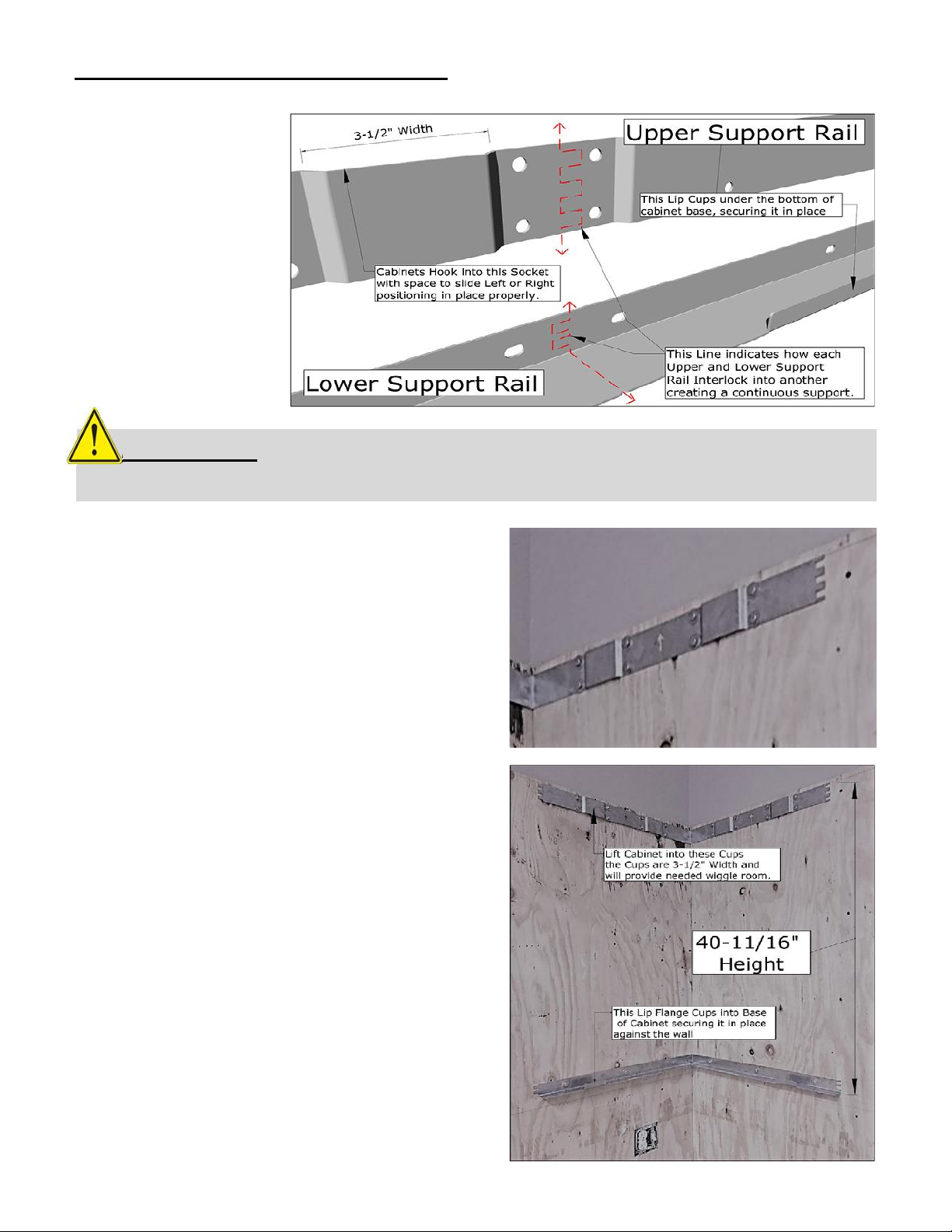
When placing the top Support Rails, pay
special attention that all Arrows are pointing
in “UP” position, otherwise the interlocking
teeth will not align. **Important Note –
you may need to thread each bolt through
the corresponding holes**
Complete all Lower and Upper Support
Rails installations for the first Wall
Cabinet position. Confirm all positions
are correct as the rest of the installation
will follow along, if any errors this will
cause a larger issue.
Confirm Spacing Height measured from
base of Lower Support Rail to the Top
Edge of Upper Support Rail when secured
in place. Again Confirm all Elevations
are precise using Leveler Tool.
All Upper and Lower
Support Rails feature
Interlocking Teeth
that are designed to
make it much easier to
build out even
horizontal straight
lines, one piece at a
time.
ATTENTION: When mounting Upper Support Rails – be sure to always face
Arrows in “UP” positions, or the interlocking teeth will not line up.
4.WALL CABINETS – UPPER SUPPORT RAILS

Page 6
5.WALL CABINETS – POSITIONING CABINETS
Test your installation is correct by
Placing the First Wall Cabinet into
position, follow these instructions when
placing the remaining cabinet.
Wall Cabinets are Heavy, and requires
at least two Adults to lift into position.
It may be best to use a Four-Wheeler
Dolly to position Cabinets on then roll
into closer proximity to final resting
point.
ATTENTION: DO NOT Place additional cabinets until ALL Upper and Lower
Support Rails are installed in any one direction.
See the Hangers on the back top of
each wall cabinet, these will hook into
the Upper Support Rail.
Once the cabinet is lifted and the
Hangers are hooked into the
corresponding Upper Support Rail –
Pockets, there is a small space on the
Right & Left of each Pocket so cabinet
can be correctly adjusted.
You will need to additionally lift the
Base of Cabinet into the Lower
Support Rail, Shelf-Lip which Cups
around the Back Bottom Base of
Cabinet.

Page 7
6.WALL CABINETS – PANEL & CABINET DETAILS
Continue placing Support Rails along one
direction off from the starter cabinet position.
Install all support rails in any one direction
before adding more cabinets.
If placing any of the following cabinets
SWC18CSDL, or SWC18CSDR, these
cabinets are most often used for Sink or
Cleanup areas and are shorter in height and
will not have any Bottom Support Rails.
If placing any Spacers, remember to also
place the Spacer Rail Supports, these do not
attach to the spacer panel themselves, instead
they work to create the correct spacing
between other wall cabinets positions.
When placing either of the following cabinets
SWC18CSDL, or SWC18CSDR, be sure to
place the End Panel, Item No. SWC21EP
onto the opposing cabinet lower base side,
this will seal the inner area on the inside
ATTENTION: Be sure to install each Crown Molding Panel on top of each
cabinet before lifting cabinet into place. Handles can be placed Last.

Page 8
7.WALL CABINETS – SECURING CABINETS
Place the remaining cabinets along pre-installed Support Rails, remember to confirm all Top
of Cabinet Crown Molding Panels are installed before cabinet is lifted into place. Per this
Example, we placed the following cabinets starting from the Right, SWC12SLS,
SWC30FDD, SWC18CSDR, SWC18CSDL, SWC36FDD, SWC6SPF.
Spacers Panels attached to the Front side
of wall cabinet only, using the included
“Cabinet Spacer Joint Screw & Nut”.
Thread the long screw through each hole
located on the inside left and right sides
of cabinet with doors open. Typically,
there will be Three Holes, Top, Middle,
and Bottom.
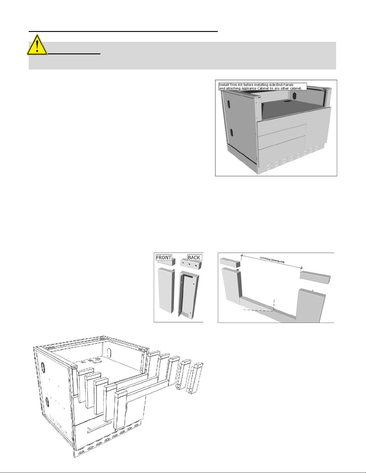
APPLIANCE BASE CABINETS – TRIM-KIT OPTIONS
First is to install any “Trim-Kits” you may have
for either large or smaller appliance cabinets in
your island configuration. At this point your
appliance cabinet should appear as shown in
the picture to the right with front, back kick
plate panels installed and the side panel if the
cabinet is on either end of your island
configuration.
Depending on the specific Appliance you have, your cabinet came with a specific
Trim
-Kit that will fit
each appliance cabinet in your cabinet island configuration. Be sure to measure the inside width of
trim kit, and match up with your own appliance. Use own discretion when with Trim-Kits, as your
specific product cut-out dimensions have not been directly confirmed by any Sunstone Metal
Products LLC. Representative or employee.
Your Trim-Kit will come with either two
smaller separate pieces also with
smaller counter rail pieces included, or
as a single larger piece with center
bottom filler rail connecting the two
sides, and separate top counter rails
pieces separate.
Each Appliance Cabinet is offered with
Five to Six Trim-Kits, each for making
its own cut-out size to accommodate
many more appliance brands available
in the market. If your trim-kit does not
fit with your appliance, please contact
your Sunstone dealer or our technical
support line at 888-934-9449
ATTENTION: Be sure to install all Trim-Kits and End Panels before any
counters are installed.
Page 9

APPLIANCE CABINETS – TRIM KIT ASSEMBLY
Page 10

APPLIANCE CABINETS - SUPPORT RAIL
The Appliance Cabinet Support Rail is located in the back of cabinet, and is used as a Counter Support,
in the event your specific appliance is either deeper or shorter. In either case you can adjust the depth
of sleeve cut-out using this rail, see the pictures below for instructions.
ALL CABINETS - COUNTER RAIL
The Cabinet Counter Rail is designed as two-fold, one to allow for adequate distance of counter to drawer
or door of cabinet as a decorative accent piece and gives you the added ability of being able to install your
counter top with a full bullnose edge, that wraps around front of cabinet edge.
Page 11

ALL CABINETS - END PANEL
ALL CABINETS - Counter Rail & End Panel
Page 12
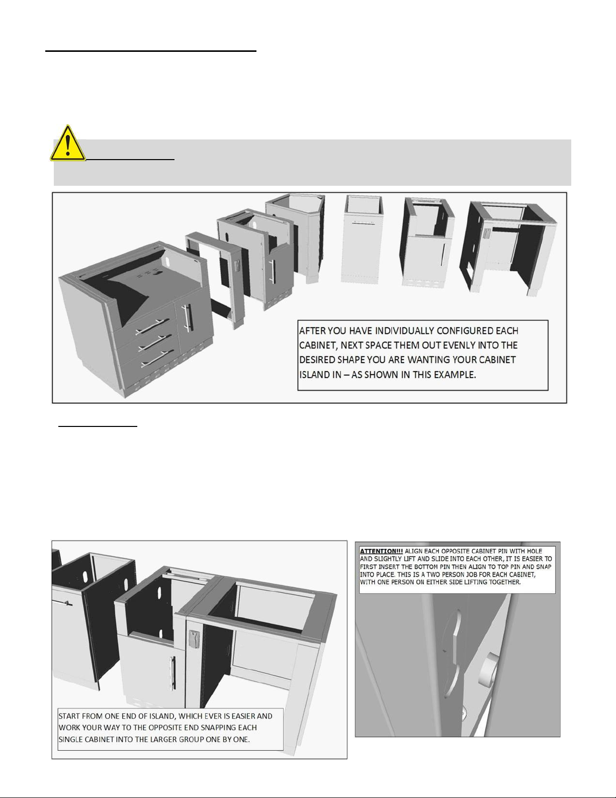
ALL CABINETS - ISLAND LAYOUT
Now that you have individually configured each cabinet, it is time to set them up into the general
layout of your island design. Be sure to give some distance between each cabinet so you can move
your body between each one.
IMPORTANT!!! You must individually attach each cabinet together, do not try and attach three or
more together at once. Using a Leveler, place on top of each cabinet group as you assemble, taking
special precaution that the top is Leveled as you go. Each peg leg is adjustable within 1-1/2” Inches,
to composite for any uneven ground, additional some leveling may be required for lower drainage
dips in your patio, but also know that as all cabinets are attached to one another, they will hold very
strong together and leveled. So if one or two cabinets are slightly elevated, this should not impact
the overall integrity of island assembly.
ATTENTION: Place all Kickplates Last after all cabinets are attached and
legs are leveled. Install Kick Plates from the Left to the Right always.
Page 13

ALL CABINETS - ISLAND LAYOUT
9. ALL CABINETS - ISLAND COMPLETION
Once all cabinets have been properly configured and attached, next is to make your final
preparation
.
Insure all Electrical Outlets and or Gas Lines have been installed with proper wiring and hoses running
through the length of the cabinet island – through each adjacent port hole into one another. Next
your
local counter installer will come to your home to do a template of Cabinet Island for final
counter installation. Last – install your Grill, Side Burners, sinks, and fridge.
Page 14

CABINET WARRANTY
SUNSTONE – CABINET WARRANTY
WARRANTY ON PARTS
CABINET STRUCTURE -----------------------------------LIMITED LIFTIME
CABINET FINISH -------------------------------------------LIMITED LIFETIME
ROD HANDLES----------------------------------------------5 YEARS
PEG LEGS --------------------------------------------------- 5 YEARS
KICKPLATES & TRIM KITS PANELS---------------------5 YEARS
LIMITED LIFETIME WARRANTY
Stainless Steel, to be from defects in material and workmanship when subjected to normal domestic use and service for the
lifetime of the original purchaser. This warranty does not include discoloration, surface corrosion, and scratches which may
occur during regular use.
LIMITED FIVE-YEAR WARRANTY
All other components including Rod Handles, Peg Legs, Kick Plates, End Panels, and Spacer Panels are warranted
to be free from defects in material and workmanship for a period of five years from the original date of purchase.
LIMITATIONS & EXCLUSIONS
1. Cabinet warranty applies only to the original purchaser and may not be transferred.
2. Cabinet warranty is in lieu of all other warranties expressed or implied and all other obligations or
liabilities related to the sale or use of its grill products.
3. Cabinet warranty shall not apply and SUNSTONE METAL PRODUCTS LLC. Is not responsible for damage
resulting from misuse, abuse, alteration of or tampering with the cabinet, accident, hostile environment,
improper installation, or installation not in accordance with the instructions contained in the User
Manual, or the local codes.
4. SUNSTONE METAL PRODUCTS LLC. shall not be liable for incidental, consequential, special or contingent
damages resulting from its breach of this written warranty or any implied warranty.
5. Some states do not allow limitations on how long an implied warranty lasts, or the exclusions of or
limitations on Consequential damages. This warranty gives you specific legal rights and you may have
other rights, which vary from state to state.
6. No one has the authority to add to or vary cabinet warranty, or to create for SUNSTONE METAL
PRODUCTS LLC. any other obligation or liability in connection with the sale or use of its products.
instructions contained in the User Manual, or local codes.
5. Shipping and handling costs, export duties, or installation cost.
6. The cost of service calls to diagnose trouble; or Removal or re-installation cost.
WHAT IS NOT COVERED & INTERNET PURCHASE DISCLAIMER
1. Shall not be responsible for and shall not pay for the following Installation or set-up of cabinet.
2. Service by an unauthorized service provider;
3. Damage or repair due to service by an unauthorized service provider or use of unauthorized parts.
4. Damage caused by accidents, abuse, alteration, misuse, installation that is not in accordance with the
Page 15
 Loading...