

Sunstone Welders
Sunstone Welders
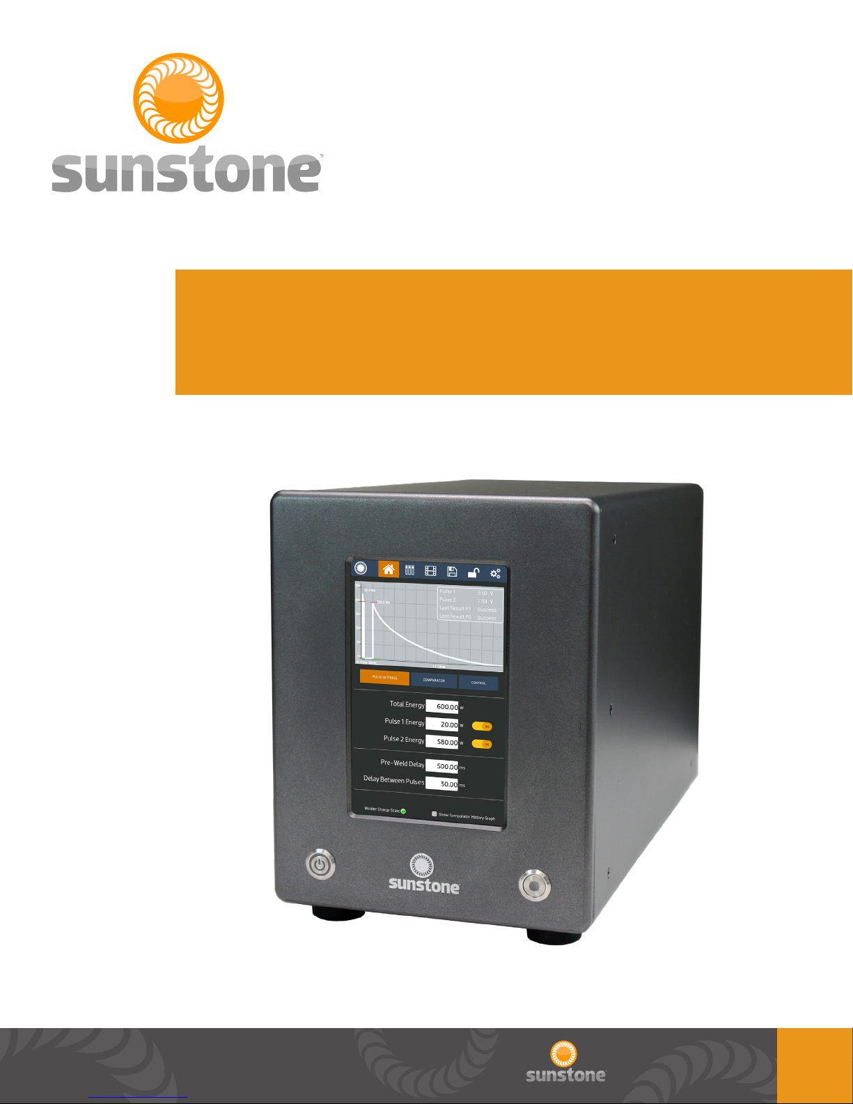
Advanced Capacitive Discharge Dual Pulse Welder
User Manual for Models: CD200DP-A, CD400DP-A, CD600DP-A
User Manual : CDDP-A

Sunstone Welders User Manual: CDDP-A
Table of Contents
FORWARD - P.3
CHAPTER 1: WELDER OVERVIEW - P.4
Features - P. 4
Applications - P. 4
CHAPTER 2: RESISTANCE WELDING - P.5
What is Capacitive Discharge Resistance Welding? - P.5
Weld Formation - P.6
Tips - P.6
Weld Pressure - P.6
Electrode Congurations - P.6
Weld Energy - P.7
CHAPTER 3: SET UP - P.7
Pre-Setup Information - P.7
Voltage and Power Requirements - P.7
Weld Actuation - P.7
Thermal Protection - P.8
Front Panel Connections - P.8
Power Button - P.8
Weld On/Off - P.8
Screen - P.8
Conguration 1 - P.11
Conguration 2 - P.11
Conguration 3 - P.12
Welder to Hand Held Attachment Setup - P.12
Roll Spot Setup - P.13
CHAPTER 4: OPERATING INSTRUCTIONS - P.14
Pulse Control - P.14
Dual Pulse Welding - P.14
Using The Dual Pulse Weld Function - P.14
Setting Pulse 1 and 2 - P.14
Energy Adjustment - P.14
Timing Diagrams - P.15
Automation - P.17
Maintenance - P.18
Safety - P.18
CHAPTER 5: USER INTERFACE - P.19
Home Screen/Pulse Settings - P.19
Comparator - P.20
2nd Comparator - P.21
Control - P.22
Side Panel Connections - P.8
USB - P.8
Back Panel Connections - P.9
Ethernet - P.9
Accessory - P.9
PLC - P.9
E-STOP - P.10
WH Control - P.10
Primary Trigger - P.10
Secondary Trigger - P.10
Negative Weld Terminal - P.11
Positive Weld Terminal - P.11
Fuse - P.11
Power Inlet - P.11
Welder to Weld Head Setup - P.11
Basic PLC I/O - P.23
Remote Schedule Select - P.24
Alarms - P.24
Import/Export - P.25
Media Screens - P.26
Save/Load Screen - P.28
Lock Screen - P.30
Settings Screen - P.31
Settings Screen Pop Ups - P.32
Warnings and Alarm Pop Ups - P.34
DATA TABLES - P.38
Additional Safety - See included Safety and Basics User Manual
Warranty - See included Safety and Basics User Manual
2

Foreword:
Thank you for choosing Sunstone Engineering and congratulations on your purchase!
You are now the proud owner of a Sunstone Capacitive Discharge (CD) Dual Pulse (DP) Welder.
This manual was designed to have you welding safely within minutes of unpacking your new welder.
Please read and follow all safety precautions before proceeding with the welding process.
At Sunstone Engineering we are committed to producing quality products and ensuring complete
owner satisfaction. If you require assistance after reading this manual, do not hesitate to contact us
at:
Sunstone Engineering R&D Corp.
1693 American Way Suite #5
Payson, UT 84651
Email: sales@SunstoneWelders.com
Voice: 801-658-0015
Fax: 866-701-1209
NOTE: The information contained in this manual is subject to change as improvements are made to
our products. Visit your product’s respective web page on www.SunstoneWelders.com for the latest
version of this document.
Copyright 2018
Sunstone Engineering
R&D Corporation
3

Sunstone Welders User Manual: CDDP-A
Chapter 1: Welder Overview
Features
Each of the Dual Pulse CD welders can be adjusted and ne-tuned to match the requirements of
countless applications. When combined with Sunstone’s line of weld heads or hand attachments, CD
welders perform strong and repeatable welds for high levels of consistency and quality control.
• Dual Pulse operation removes surface inconsistencies and contaminants
• Available with 200, 400, & 600ws of energy
• Single or Dual Pulse weld congurations
• Microprocessor controlled
• Internal thermal protection circuit
• Adjustable pulse width
• Energy storage adjustable from less than 1% to 100% capacity
• Up to 650 welds/min (using CD200DP-A)
• 110 or 220VAC input
• Simple, user-friendly interface
• Quick energy release for welding highly conductive metals
• Small heat effected weld zones
• Repeatable energy release independent of line voltage uctuations
• Extremely ne energy adjustment (0.01ws increments)
Applications
Sunstone Capacitive Discharge Welders are used all across the globe for a variety of different welds.
Some of the most common uses of our CD Welders include:
• Battery pack manufacturing and repair
• Honeycomb applications
• Aerospace applications
• Automotive welding
• Cross wire welding
• Thermocouples
• Electronic components
• Thin sheet and wire welds of:
• Copper
• Aluminum
• Brass
• Steel
4
There are many other applications for Sunstone’s line of Capacitive Discharge Welders. Let us know
if you nd a unique use for our welding equipment.
Chapter 2: Resistance Welding
What is Capacitive Discharge Resistance Welding?
Capacitive discharge resistance welders, also called capacitive discharge or CD welders, utilize
internal capacitors to store energy. These capacitors are able to discharge large amounts of energy
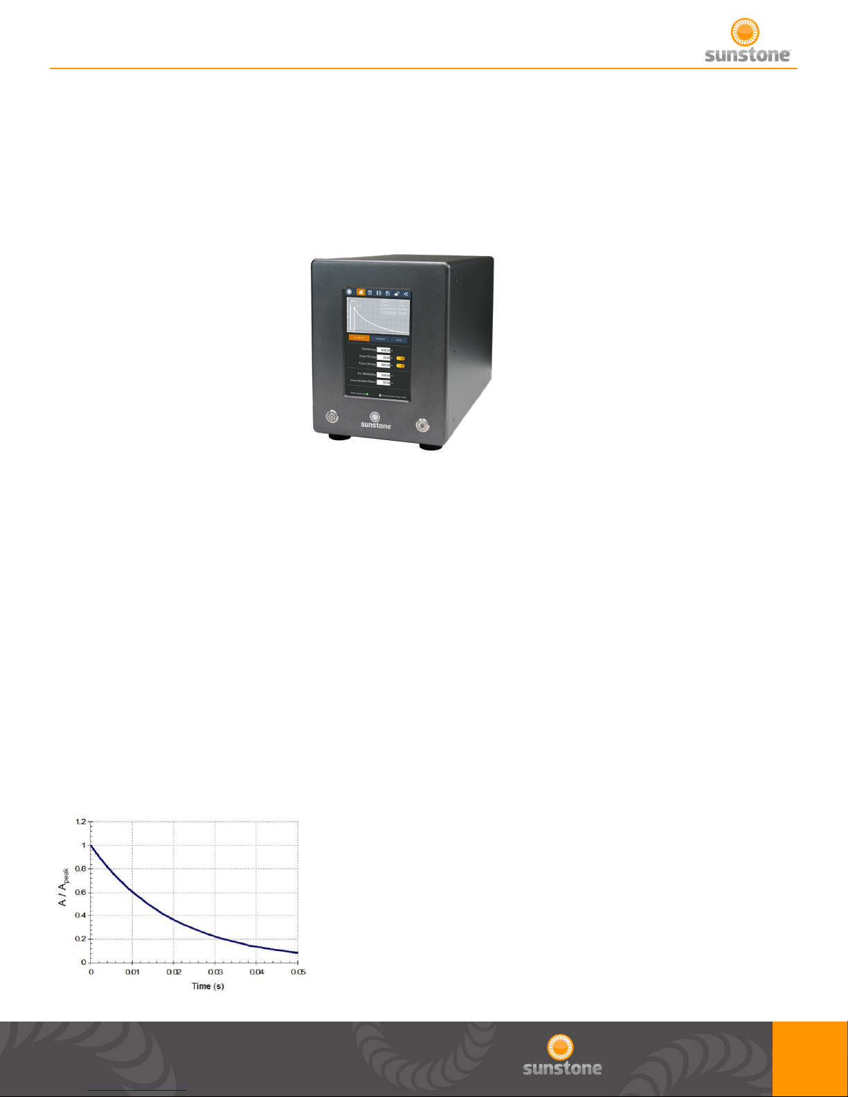
very rapidly. The rapid discharge of energy is critical to forming the weld nugget. Formation of the
weld nugget occurs during the rst few milliseconds of the welding process. Sunstone’s proprietary
technology allows the energy to be discharged with very high peak currents, as seen in FIGURE 1
below, to produce the best weld nuggets.
This technology is not only designed to increase the energy delivered for weld formation but to
also minimize the heat that is spread to the surrounding material. This ‘heat-affected zone’ around
the weld can suffer from rapid heating and cooling from the weld. But with Sunstone’s proprietary
technology, this zone can be localized to just a small spot around the weld.
FIGURE 1: Sample capacitor discharge curve with high peak current.
5
Sunstone Welders User Manual: CDDP-A
WELD FORMATION
Spot welding relies on metal resistivity (resistance) to heat and fuse metal. A large current is passed
through the workpiece metal. Energy is dissipated due to metal resistance in the form of heat which
melts and fuses the weld materials. The welder must overcome both the contact resistance and the
bulk resistance of the material in order to begin the melting process.
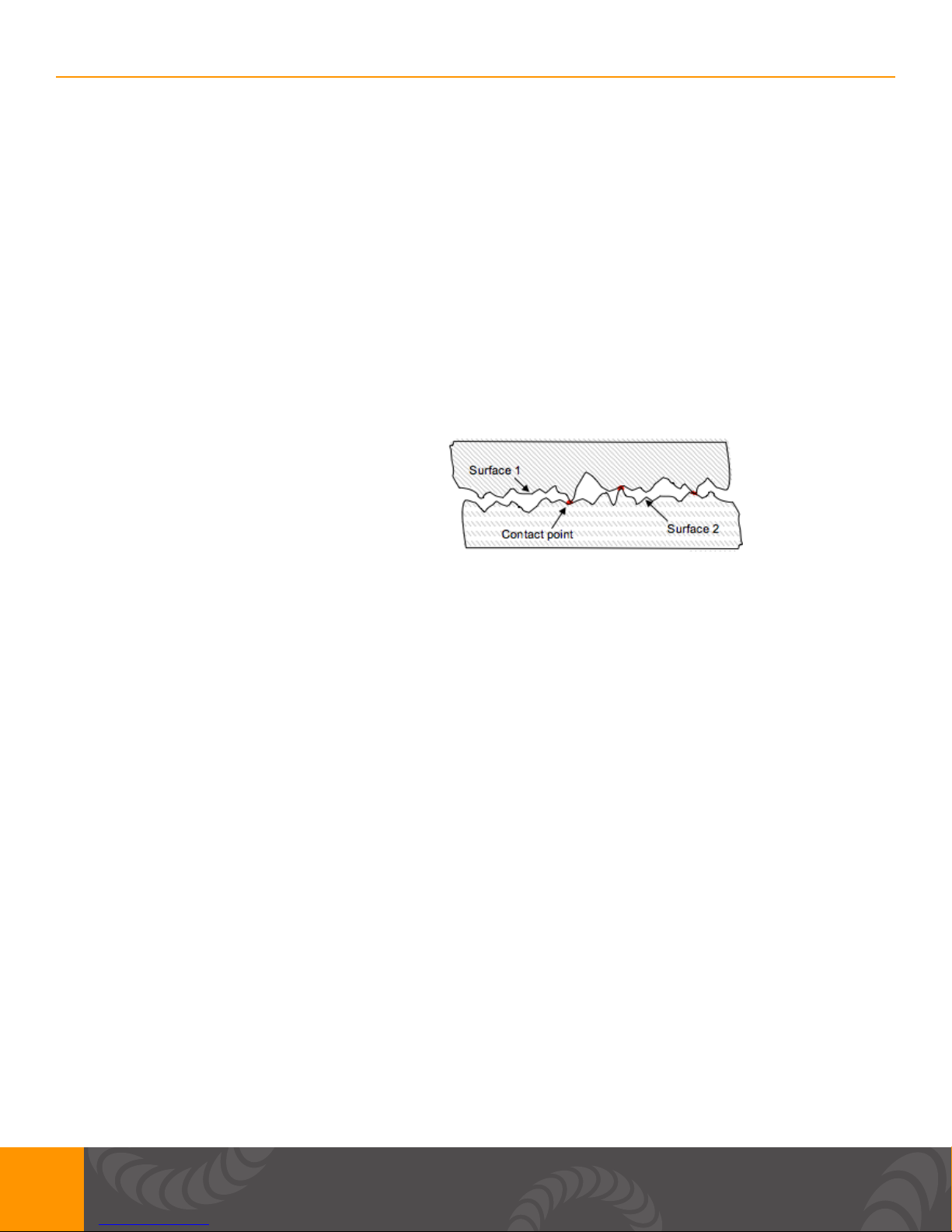
FIGURE 2 below shows an example of a micro-scale surface prole. On the micro-scale, material
surfaces are rough and only contact in a limited number of locations. In the rst few milliseconds of
weld formation, the high-resistance metal bridges melt, allowing other bridges to come into contact
to continue the melting process. When all of the bridges have fused, the contact resistance is zero.
The bulk resistance of the metal then plays the nal role in the weld formation.
FIGURE 2: On the micro-scale, surface
roughness limits surface-to-surface contact.
More contact points result in a lower contact
resistance.
Tips
WELD PRESSURE
Several other factors play a part in the contact resistance. The larger the contact resistance the
hotter the resultant weld. On the micro-scale, contact resistance is reduced when more metal bridges
or contact points are formed (see FIGURE 2). Using more electrode pressure creates more metal
bridges. This results in a lower contact resistance and a cooler weld. Conversely, light electrode
pressure results in less metal contact, higher resistance, and a hotter weld. An appropriate amount of
pressure should be used to ensure good weld strength.
ELECTRODE CONFIGURATIONS
FIGURE 3 shows several electrode congurations used in resistance welding. FIGURE 3a is called
an opposed conguration. Current is passed from one electrode through both workpieces and out
an opposing electrode. FIGURE 3b shows a step electrode conguration. This conguration is
used when there is access to only one side of the workpiece and an electrode can be placed on
both materials. FIGURE 3c is a series or parallel conguration. Electrodes can only be placed on
one metal surface from one side. Current is divided between the two parts. This weld conguration
requires more weld energy.
6
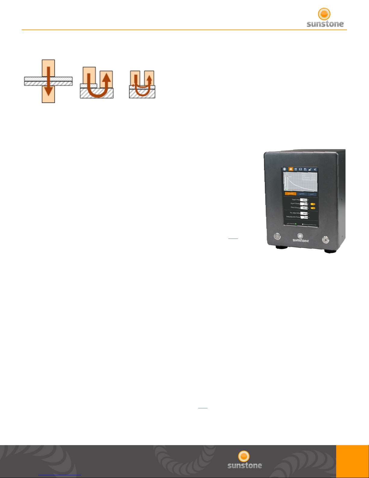
FIGURE 3: Resistance Welding Electrode Congurations:
a. Opposed b. Step c. Series / Parallel
WELD ENERGY
Sunstone capacitive dual pulse welders allow adjustment of the stored
energy via the touch screen user interface, shown in FIGURE 4. The
energy is then displayed in watt seconds (Joules) as a waveform
graph on the user interface LCD display. The Total Stored Energy
will change how much energy is stored in the internal capacitors and
directly corresponds to the peak current available. The energy of Pulse
1 and Pulse 2 can be changed independent of each other, but the Total
Stored Energy of Pulse 1 and Pulse 2 added together must be lower
than the Total Stored Energy. More information can be found on p.14 of
this manual.
FIGURE 4: Touch Screen Interface
Chapter 3: Setup
Pre Setup Information
VOLTAGE AND POWER REQUIREMENTS
Sunstone Advanced Capacitive Discharge Dual Pulse (CDDP-A) welders are equipped with universal
power supplies and can be used with either 110 or 220VAC. No voltage selection is required prior to
connecting and powering on the welder. The welder will detect the voltage, and make the appropriate
adjustments automatically.
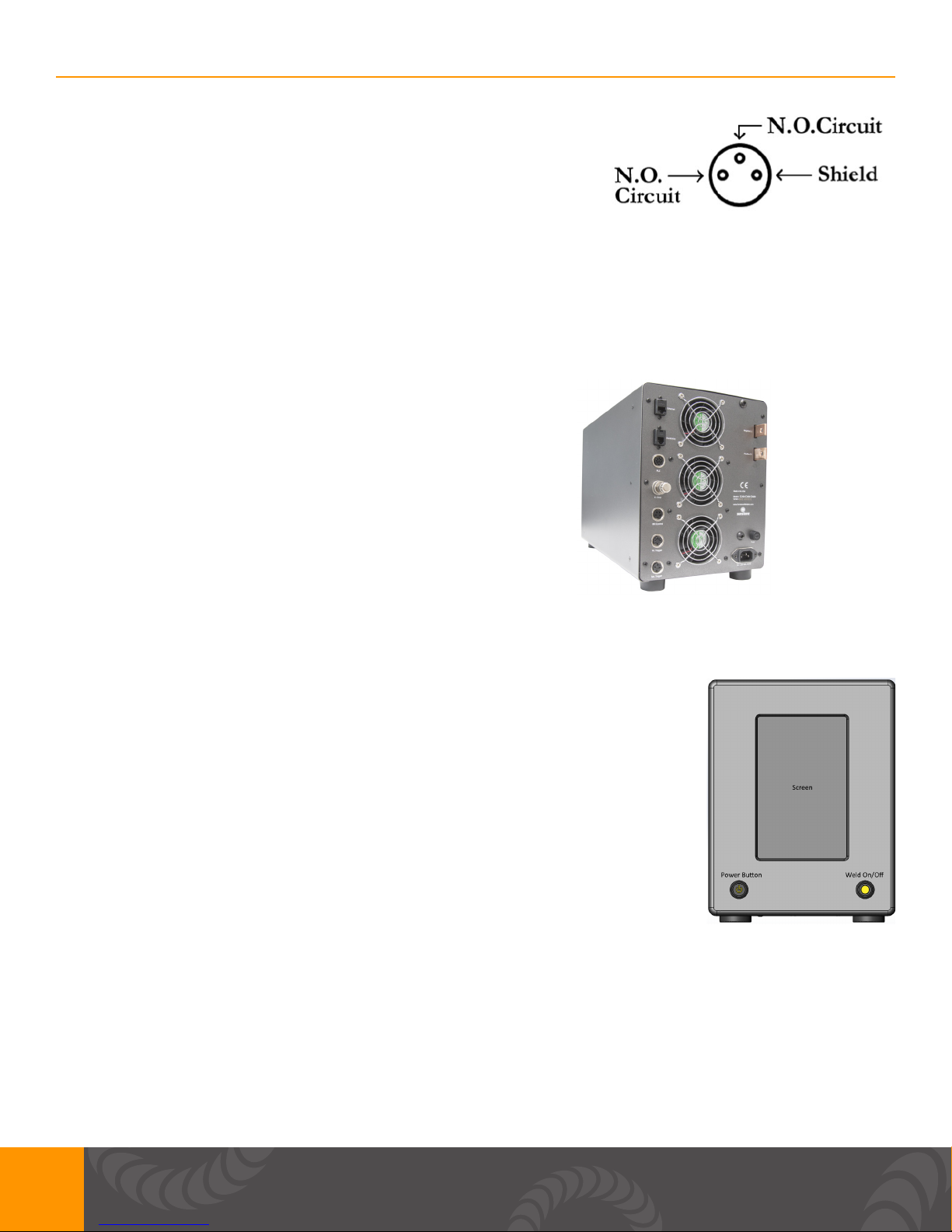
WELD ACTUATION
The CDDP-A welders are actuated by means of an external trigger port located on the back of
the welder (see FIGURE 5). The trigger uses a 3 DIN (p.12) connector and requires shielded wire.
FIGURE 5 shows the proper pin placement for custom external trigger cables. The standard external
trigger cable connector is an SD-30LP made by CUI Inc.
7
Sunstone Welders User Manual: CDDP-A
FIGURE 5: External Trigger Wiring Diagram - N.O. stands for
Normally Open.
THERMAL PROTECTION
Sunstone’s capacitive discharge welders are equipped with temperature sensors. If the unit is hot it
will warn the user with a pop up. After the unit is cool enough to operate, the welder will go back to
normal operation. Please maintain a clear space of 6+ inches around the welder fans. FIGURE 6,
below, shows the location of the fans on the back of the welder.
FIGURE 6: For proper cooling, ensure all fan locations are
unobstructed.
Front Panel Connections
POWER BUTTON: A latching push button that turns the unit on when depressed.
If unpressed the unit will turn off. Warning: DO NOT turn the welder off during
boot up. Allow enough time for unit to completely boot up before turning unit
off.
WELD ON/OFF: A latching push button that enables welding when depressed.
An LED will light up when the push button is depressed completely. This
indicates that the weld is enabled. We always recommend to turn OFF the
Weld On/Off switch whenever making changes to electrodes or other welding
equipment connected to the welder.
SCREEN: 8” capacitive touch screen with a WXGA LCD. This makes it
convenient for navigating the interface and setting up the machine.
FIGURE 7: Front Panel
Side Panel Connections
USB: A USB ash drive (thumb drive) can be used to update the machine. A USB ash drive can
also be inserted when data collection in desired from the weld process. You can also connect a
compatible USB wired mouse to navigate the interface.
8
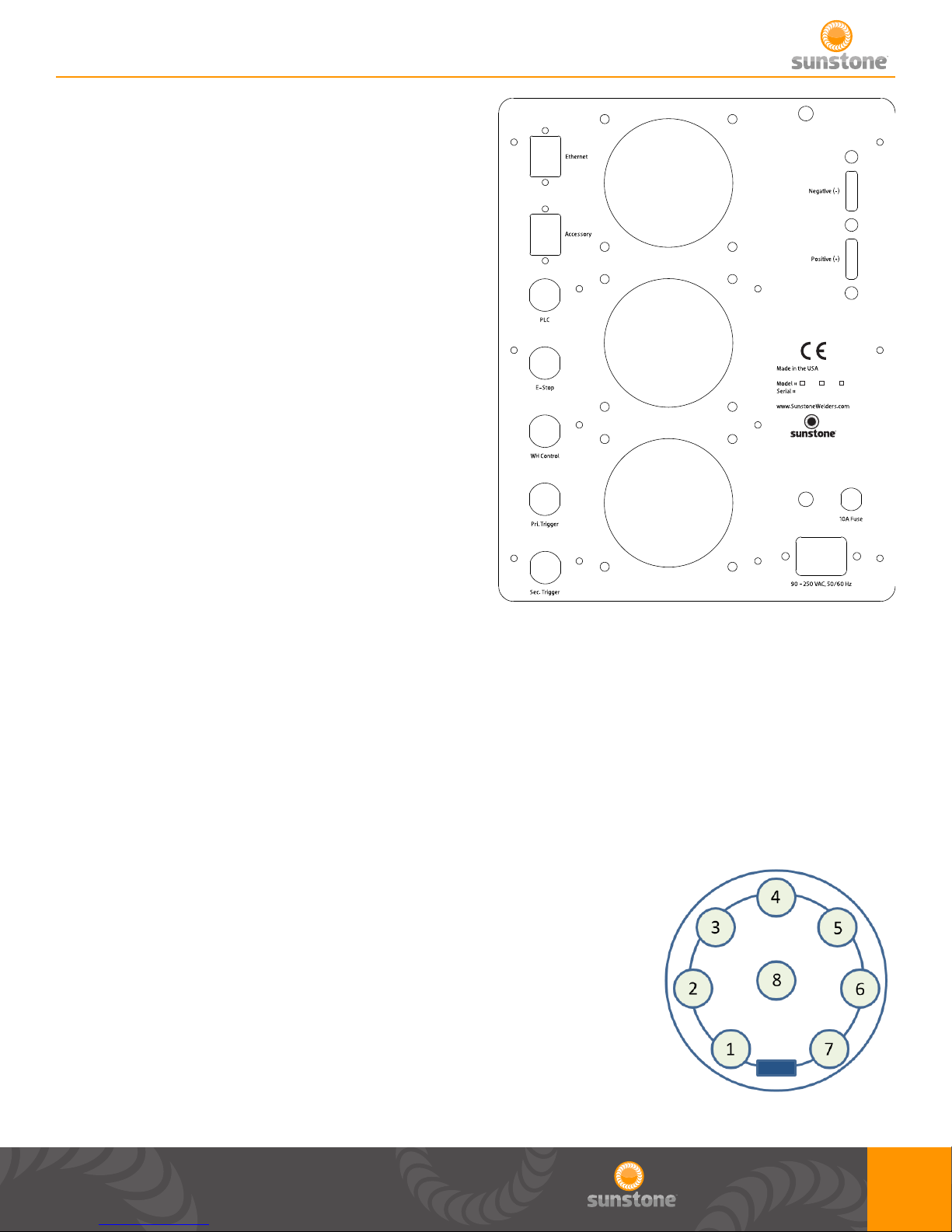
Back Panel Connections
All DIN connections are displayed as viewed from the
back panel.
ETHERNET: Plug an Ethernet cable into this port if you
desire to control the CDDP-A with a PLC.
ACCESSORY: Used to connect external accessories
(Coming Soon).
FIGURES 9 through 13 show the DIN connectors
pin-out, looking at the back panel.
200 400 600
FIGURE 8: Back Panel
PLC: MATES TO SD80LP
1: GND/Shield
2: +12V Current Limited
3: PLC Input 1. Short this pin with Pin1 (GND) to trigger an action.
4: PLC Input 2. Short this pin with Pin1 (GND) to trigger an action.
5: Weld Ready. Pull this pin up to +12V by connecting it with Pin 2 (+12V). Signal will go low 0V,
when weld is ready.
6: Alarm. Pull this pin up to +12V by connecting it with Pin 2 (+12V).
Signal will go low 0V, when alarm has occurred.
7: PLC Output 1. Pull this pin up to +12V by connecting it with Pin 2
(+12V). Signal will go low 0V, when this output has been enabled.
8: PLC Output 2. Pull this pin up to +12V by connecting it with Pin 2
(+12V). Signal will go low 0V, when this output has been enabled.
*If you choose to use the software E-STOP alarm as one of the PLC
outputs on the 8 DIN PLC connector, realize that this signal will only be
a pulse that will last a minimum of 50 milliseconds.
FIGURE 9: PLC Connector (SD-80LS)
9
Sunstone Welders User Manual: CDDP-A
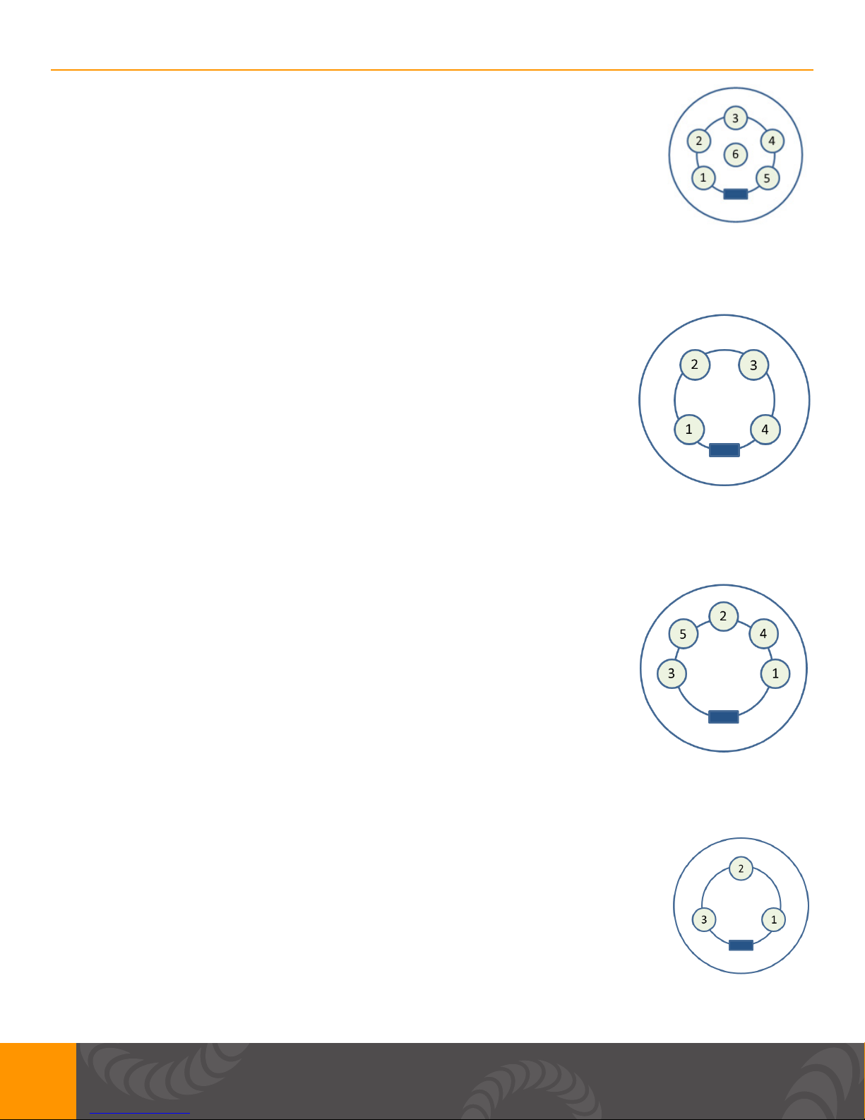
ESTOP: MATES TO SD60LP
Pin 1: GND/Shield
Pin 2 & 3: Normally open, ESTOP enabled. Close circuit to disable ESTOP
FIGURE 10: E-STOP Connector (SD-60LS)
WH CONTROL: MATES TO SD40LP
Pin 1: GND/Shield
Pin 2: Weld Head Actuation 2. +12VDC(0.5A Max) is sent when weld head
needs to actuate.
Pin 3: Weld Head Actuation 1. +12VDC(0.5A Max) is sent when weld head
needs to actuate.
Pin 4: GND/Shield
FIGURE 11: WH Control Connector (SD-40LS)
PRIMARY TRIGGER: MATES TO SD50LP
Pin 1: Variable Foot Pedal. Connect this to Pin5 (+12VDC) with a 10Kohm
potentiometer.
Pin 2: Primary Trigger. Connect this to pin3 (GND) when trigger is desired.
Pin 3: GND/Shield
Pin 4: Secondary Trigger. Connect this to pin3 (GND) when trigger is desired.
Pin 5: +12VDC limited.
FIGURE 12: Primary Trigger Connector (SD-50LS)
SECONDARY TRIGGER: MATES TO SD30LP
Pin 1: Not Connected
Pin 2: +12V
Pin 3: Secondary Trigger. Connect this to pin 2(+12VDC) when trigger is desired.
10
FIGURE 13: Secondary Trigger (SD-30LS)
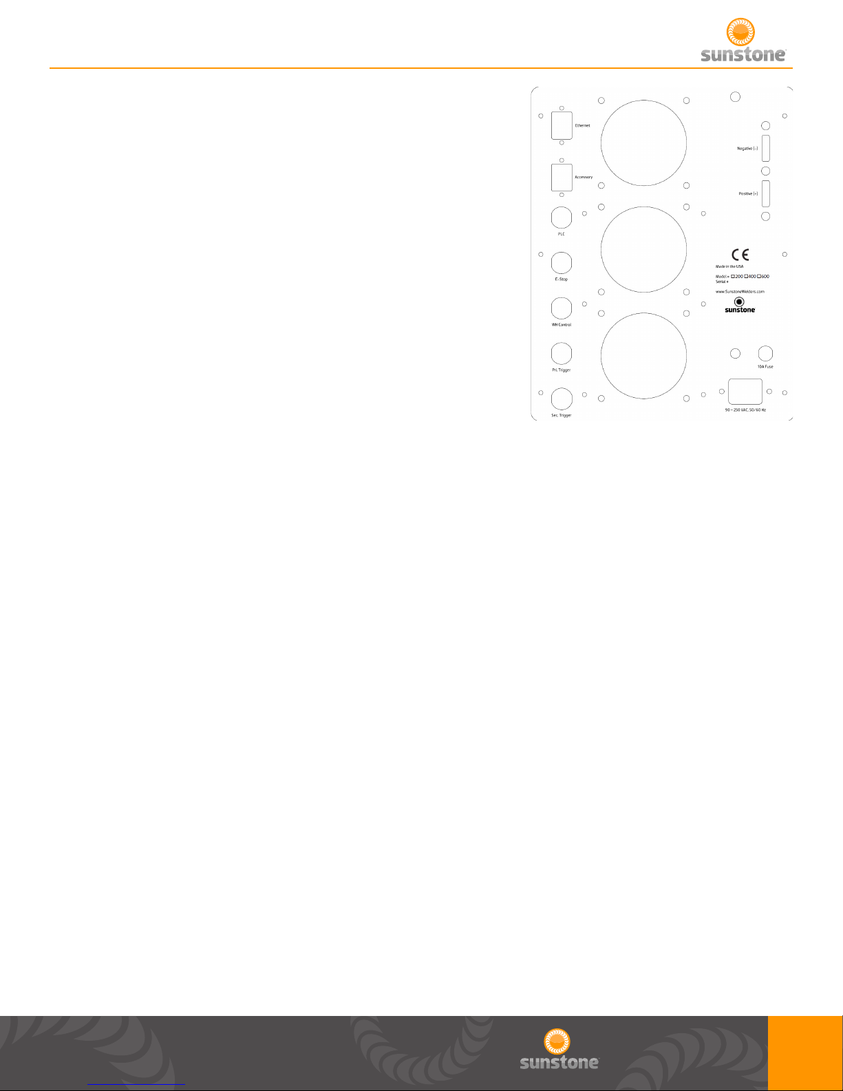
NEGATIVE : Negative weld terminal. Connect weld cable
using ¼-20 x ¾” bolt and nut. Make sure your total weld cable
resistance is greater or equal to 1 milliohm of resistance.
POSITIVE +: Positive weld terminal. Connect weld cable using
¼-20 x ¾” bolt and nut. Make sure your weld cable resistance is
greater or equal to 1 milliohm of resistance.
FUSE: 10A fuse rated for up to 250VAC
90-250 VAC, 60Hz
POWER INLET: Plug wall power into this port. Can accept voltage
from 90-250VAC at a frequency of 50/60Hz.
FIGURE 14: Back Panel
Welder to Weld Head Setup
There are 3 possible congurations when using a weld head or hand attachment.
CONFIGURATION 1: Using manual weld head and driven separately from the CDDP-A welder.
1. Remove the welder from the box and place it on a secure work surface.
2. Connect the female end of the power cord into the back of the welder and the male end into an AC
power outlet.
3. Attach weld head or hand attachment cables to negative and positive terminals.
4. Ensure either E-STOP bypass plug in plugged in or an E-STOP switch is plugged into the 6 DIN
E-STOP connector labeled “E-STOP”on back panel.
5. Attach a foot pedal to secondary trigger on back panel.
6. Turn the welder on by pressing in Power button on front panel.
7. On main screen adjust you Total Stored Energy, Pulse 1 energy, and Pulse 2 energy.
8. On the control screen adjust your weld head control scheme to “Fully Manual”.
9. Enable welder, by pressing in Weld On button on front panel.
10. Trigger a weld with foot pedal.
CONFIGURATION 2: Using with weld head actuated manually and driven with the CDDP-A welder.
1. Remove the welder from the box and place it on a secure work surface.
2. Connect the female end of the power cord into the back of the welder and the male end into an AC
11

Sunstone Welders User Manual: CDDP-A
power outlet.
3. Attach weld head to negative and positive terminals.
4. Ensure either E-STOP bypass plug in plugged in or an E-STOP switch is plugged into the 6 DIN
E-STOP connector labeled “E-STOP”on back panel.
5. Attach a foot pedal to secondary trigger on back panel.
6. Attach the weld head 4 DIN actuation cable to the 4 DIN connector labeled “WH Control” on back
panel.
7. Turn the welder on by pressing in Power button on front panel.
8. On the main screen adjust your Total Stored Energy, Pulse 1 energy, and Pulse 2 energy.
9. On the control screen adjust your weld head control scheme to “Fully Manual”.
10. Enable welder, by pressing in Weld On button on front panel.
11. Trigger a weld with foot pedal.
CONFIGURATION 3: Using air actuated weld head and driven with the CDDP-A welder.
1. Remove the welder from the box and place it on a secure work surface.
2. Connect the female end of the power cord into the back of the welder and the male end into an AC
power outlet.
3. Attach weld head to negative and positive terminals.
4. Ensure either E-STOP bypass plug in plugged in or an E-STOP switch is plugged into the 6 DIN
E-STOP connector labeled “E-STOP”on back panel.
5. Attach a foot pedal to primary trigger on back panel.
6. Attach the weld head 3 DIN trigger cable to the secondary trigger on back panel.
6. Attach the weld head 4 DIN actuation cable to the 4 DIN connector labeled “WH Control” on back
panel.
7. Turn the welder on by pressing in Power button on front panel.
8. On the main screen adjust your Total Stored Energy, Pulse 1 energy, and Pulse 2 energy.
9. On the control screen adjust your weld head control scheme to “Auto with Timing” or “Auto with
Trigger”.
10. Enable welder, by pressing in Weld On button on front panel.
11. Trigger a weld with foot pedal.
Welder to Hand Held Attachment Setup
QUICK START SET UP OF HAND HELD ATTACHMENTS TO CDDP-A WELDERS
Sunstone Engineering manufactures a variety of welding hand pieces to accommodate a diverse
range of welding applications. Hand piece welding attachments allow ease of use and versatility.
1a. Turn off welder and unplug AC power cord for safety.
1b. Remove hand held attachment from its package.
12

2a. Single probe, dual probe, and tweezer hand held attachments - Connect
the hand held attachment cables to the negative and positive terminals on
the back of the welder, then connect the 3 pin actuation foot pedal cable to
the back of the welder.
2b. Pressure actuated hand attachments - Connect the hand held
attachment cable to either of the terminals on the back of the welder and the
grounding clip cable to the other terminal. Then attach the trigger cable to the
back of the welder.
3. Plug the welder power cable into an AC power outlet.
4. Turn the welder on and set the desired energy settings.
Roll Spot Setup
QUICK START SET UP OF CDDP-A ROLL SPOT HAND ATTACHMENT
Roll Spot is a function that allows users to perform a continuous string of welds for any prolonged
time period – for as long as the trigger signal is actuated. The Roll Spot function requires an
attachment that is specically designed for roll spot welding.
1a. Turn off welder and unplug AC power cord for safety.
1b. Remove the roll spot attachment from its package.
2. Connect the roll spot cable to the terminals on the back of the welder and the grounding clip cable
to the other terminal. Then attach the trigger cable to the back of the welder.
3. Plug the welder power cable into an AC power outlet.
4. Turn the welder on and set the desired energy settings.
5. Roll Spot mode can be turned on or off in the “Control” tab within the home screen.
a. In Roll Spot mode, the system has an adjustable “Welds per second” text entry box that
affects the frequency or rate of welding while a trigger signal is maintained.
b. In Roll Spot mode, both pulses can be used, but the comparator is disabled.
c. In Roll Spot mode, the device will continuously weld at an adjustable rate for as long as
the trigger signal is maintained. If using a foot pedal, the welder will continue to weld for as
long as the foot pedal is depressed. If using a pressure actuated hand piece, the welder will
continue to weld for as long as the pressure actuated switch is engaged.
d. In Roll Spot mode, two variables will affect the time between each weld. The rst is an
adjustable “welds per second” text entry box that can be set by the operator. The second factor
is the recharge time between welds. This is determined based on the energy setting. The
higher the weld energy, the longer the delay between welds will be.
e. When in Roll Spot mode, the operator can choose to use single or dual pulse. When dual
pulses are chosen, operator can change the “Delay Between Pulses” text entry box to adjust
the this delay to match the delay between welds.
13

Sunstone Welders User Manual: CDDP-A
Chapter 4: Operating Instructions
Pulse Control
DUAL PULSE WELDING
Sunstone dual pulse welders have two pulse width energy controls. Each pulse can be adjusted
separately or turned off if desired. Pulse 1 is adjustable between 0.1WS and 30% of Total Stored
Energy. Pulse 2 is adjustable between 0.1WS and 100% of Total Stored Energy. In order for Pulse
2 to use all of the Total Stored Energy, Pulse 1 must be disabled. When Pulse 1 is enabled, Pulse 2
can only use the remaining Total Stored Energy.
USING THE DUAL PULSE WELD FUNCTION
Using multiple pulses increases weld quality. In dual pulse mode Sunstone welders will re twice
from a single actuation. The rst pulse is used to remove surface inconsistencies and contaminants
which helps to displace oils, break through oxide layers, and seat the welding electrodes.
FIGURE 15: This shows what the welder discharge curve would
look like when using the dual pulse setting as outlined above.
SETTING Pulse 1 AND 2
The Pulse 1 energy setting should be chosen such that the parts adhere weakly. To determine Pulse
1, turn off Pulse 2 and do a series of test welds starting at a low pulse energy setting. Increase the
pulse energy about 3% every test until the parts stick together to achieve maximum heat. Pulse 1
energy is typically below 10%. Pulse 2 energy is typically between 50% and 70%. A test weld should
be performed and pulled apart to determine weld strength. A nickel strip to nickel plated steel weld,
typically seen in battery pack manufacturing, should pull apart leaving holes in the thin nickel metal
and leaving the weld nuggets on the battery terminal. Thicker materials should be pulled with a
specic pull force requirement in mind.
ENERGY ADJUSTMENT
Each Sunstone welder is fully adjustable between its minimum and maximum energy. Sunstone
capacitive dual pulse welders have weld repetition rates of up to 650 welds/min. See Table 2 on page
37 for additional details on weld repetition rates. The weld energy text entry box can be used to set
14

the total welder energy storage and is also used to set the peak weld current. The pulse energies are
then adjusted to provide the appropriate weld energy released during each weld.
Timing Diagrams
D1: A delay that occurs from the time primary trigger is triggered and the signal to the weld head is
sent. Typical time for this is between 1 and 50 milliseconds.
D2: A delay that occurs from the time the weld head is engaged and when trigger 2 is triggered.
D3: A delay that occurs from the time the secondary trigger is triggered and the weld occurs. Typical
time for this is between 1 and 50 milliseconds.
Pulse 1: The duration of this delay is dependent on the energy programmed on welder for Pulse 1.
Cool: The duration of delay is dependent on the time programmed on welder for time between pulses.
User can select between 1 and 100 milliseconds. This time will be ignored if either pulse is disabled.
Pulse 2: The duration of this delay is dependent on the energy programmed on welder for Pulse 2.
D4: After this delay, alarms and warnings are sent. Typical time for this is between 1 and 50
milliseconds.
D5: After this delay the Weld Ready signal will return to a high position. This delay will depend on the
time needed to charge to the desired energy, but will typically be between 50 and 5000 milliseconds.
15

Sunstone Welders User Manual: CDDP-A
D1: A delay that occurs from the time primary trigger is triggered and the weld ready signal changes
to a low value. Typical time for this is between 1 and 50 milliseconds.
Pre-Weld: A user dened delay that happens before the signal to the weld head is sent. Can be set
between 1 and 10000 milliseconds.
Squeeze Time: A user dened delay that occurs from the time the weld head signal is sent and the
beginning of pulse 1.
Pulse 1: The duration of this delay is dependent on the energy programmed on welder for pulse 1.
Cool: The duration of this delay is dependent on the time programmed on welder for time between
pulses. User can select between 1 and 100 milliseconds. This time will be ignored if either pulse is
disabled.
Pulse 2: The duration of this delay is dependent on the energy programmed on welder for pulse 2.
Hold Time: A user dened delay that occurs from the time pulse 2 ends and the weld head begins to
return to home position.
D2: After this delay the Weld Ready signal will return to a high position. This delay will depend on the
time needed to charge to the desired energy, but will typically be between 50 and 5000 milliseconds
minus the length of the hold time.
D1: A delay that occurs from the time primary trigger is triggered and the weld ready signal changes
to a low value. Typical time for this is between 1 and 50 milliseconds.
Pre-Weld: A user dened delay that happens before the signal to the weld head is sent. Can be set
between 1 and 10000 milliseconds.
16

D2: A delay set to allow time for the weld head to fully extend. Once the weld has fully descended,
the weld discharge will be triggered. This will timeout after 10000 milliseconds.
Pulse 1: The duration of this delay is dependent on the energy programmed on welder for pulse 1.
Cool: The duration of this delay is dependent on the time programmed on welder for time between
pulses. User can select between 1 and 100 milliseconds. This time will be ignored if either pulse is
disabled.
Pulse 2: The duration of this delay is dependent on the energy programmed on welder for pulse 2.
Hold Time: A user dened delay that occurs from the time pulse 2 ends and the weld head begins to
return to home position.
D3: After this delay the Weld Ready signal will return to a high position. This delay will depend on the
time needed to charge to the desired energy, but will typically be between 50 and 5000 milliseconds
minus the length of the hold time.
Automation
The CDDP-A units will come with a basic PLC connection. For more information on pinout and
connections, please refer to the Back Panel Connections section of the user manual on p. 9.
• Through the 8 DIN connector a PLC has access to the following inputs:
▪ Two general inputs. (Choose from the list below)
▪ Clear Alarm
▪ Primary Trigger
▪ Secondary Trigger
▪ Lockout
▪ Remote Schedule Select
• When this option is selected it will use both inputs. While using Remote Schedule
Select the user can choose which saved welds are to be used via the “Remote
Schedule Select” sub tab within the PLC main tab.
• Through the 8 DIN connector a PLC has access to the following outputs:
▪ Two general outputs (Choose from the list below)
▪ Weld Ready
▪ Weld Good
▪ Weld No Good
▪ Any Alarm
▪ Any Warning
▪ Emergency Stop
▪ Alarm: Temperature
▪ Alarm: Comparator Failures in a row
17

Sunstone Welders User Manual: CDDP-A
▪ Alarm: Electrode Stuck
▪ Alarm: Weld Counter Preset Limit
▪ Alarm: Invalid Remote Schedule Selection
▪ Alarm: Wrong trigger detected
▪ Alarm: Trigger in No Weld State
▪ Alarm: Part Check Failed
▪ Warning: Temperature
▪ Warning: Comparator Failures in a Row
▪ Warning: Weld Counter Preset Limit
▪ Weld Ready
▪ Alarm
• An ESTOP is available for safety. It is normally open and engaged. It must be closed to
disengage the E-STOP. Pin out information can be found on p. 9.
• Ethernet (Coming Soon)
▪ This is available for those who would like to control the welder, with a PLC, through Ethernet.
Maintenance
• Internal verications can be performed, but can only be accessed through a technical support
screen.
• This can be performed anytime the welder seems to be creating weak welds.
• User will want to perform this Internal verication at least once a year to ensure that their
welder is performing optimally.
• Certicate of Calibration
• This is a service that Sunstone Engineering can perform. Contact Sunstone Support if
desired.
Safety
Safety Precautions for Mechanical Moving Parts
• Refer to the user manual included with your weld head or hand piece.
• Before pressing foot pedal and triggering weld, make sure nothing is obstructing the
electrodes, other than the workpiece being welded.
• If maintenance or setup is required put the welder in a “Weld Off” state, or turn unit off before
adjusting weld head.
18

Chapter 5: User Interface
Home Screen/Pulse Settings
1. Navigation Bar: Home, Communications,
Media, Save/Load, Lock, Settings
2. Waveform display of current energy settings.
a. Voltage is displayed on the y-axis, time is
displayed on the x-axis
b. The green lines indicate the lower limit of
the comparator values.
c. The red lines indicate the upper limit of the
comparator values.
d. Waveform background color is orange
when “Weld On” button is turned on and
depressed; gray when turned off.
3. Shows Active Schedule (when enabled, also
shows comparator results from previous
weld).
4. Pulse Settings tab within Home screen
5. Total energy stored in welder
1.
3.
2.
4.
5.
6.
7.
a. All or part of this energy can be divided into
Pulse 1 and Pulse 2.
b. In order for Part Check to work as intended
a Total Stored Energy must be set to a
minimum of 25WS for CD600DPA, 20WS
for CD400DPA, or 15WS for CD200DPA.
6. Amount of energy to be discharged during
Pulse 1 weld. Can be turned on or off.
7. Amount of energy to be discharged during Pulse 2 weld. Can be turned on or off.
8. Amount of time that will occur before weld process begins.
a. Only occurs for rst weld. During Roll Spot, Pre-Weld delay is ignored for all subsequent welds.
9. Amount of time that will occur between pulses when both pulses are enabled.
10. Shows the charge state of the welder. Is black when welder is not ready to weld or unit is in
“Weld Off” state. Will turn green when charged and ready. Will turn red when unit is in emergency
stop.
8.
9.
10.
19

Sunstone Welders User Manual: CDDP-A
Comparator
1. The Comparator tab within the Home screen.
2. A generated waveform of the previous weld.
3. The user can choose three different types of
comparators; voltage, current, and/or power.
The green dots will turn red if that type of
comparator fails.
a. User can choose to compare any or all of
the different types.
4. User can choose whether to use the
comparator on the rst or second pulse.
5. Each pulse has an upper limit.
6. Each pulse has a lower limit.
7. The previous weld peak result is displayed
here for Pulse 1 and Pulse 2.
a. The result will be green if passed and red if
failed.
8. User can choose to continue to Pulse 2 if
Pulse 1 fails or to stop the weld.
9. Shows the results of past weld results.
2.
1.
3.
4.
5.
6.
7.
9.
8.
20

2nd Comparator
1. When this box is checked the histogram will
appear instead of the single previous weld
result.
2. A histogram of previous weld results.
a. It shows the upper and lower limit.
b. Shows the median line between upper and
lower limit.
c. Green dots are passed results and red dots
are failed results
a
b
a
2.
c
1.
21

Sunstone Welders User Manual: CDDP-A
Control
1. Control tab within the main weld screen
2. Weld head is being used
3. Weld head control scheme
a. Fully Manual
i. Squeeze Time and Hold Time are
ignored, because user will bring weld
head down manually and also trigger
manually. Primary trigger will actuate
weld head and secondary trigger will
trigger weld discharge.
b. Auto With Timing
1.
i. Squeeze Time and Hold Time are
used.
ii. Primary trigger starts the weld process
c. Auto With Trigger
i. Squeeze Time is not used, because
weld head will trigger weld. Hold Time
is used.
ii. Primary trigger starts the weld
process.
4. The time the weld head is given to
squeeze weld piece before a weld will
occur. Is disabled when in “Fully Manual”
mode shown in item 3.
5. The time the weld head stays actuated
after the weld has occurred. It is disabled when in “Fully Manual” mode shown in item 3.
6. When Roll Spot is enabled, adjust this to change the rate at which your welder will weld. Note: At
3.
2.
4.
5.
6.
higher powers, charge times will be longer and will affect the weld per second rate. Comparator
will be disabled while Roll Spot is enabled.
22

Basic PLC I/O
1. PLC tab within communication screen
2. Basic PLC I/O sub tab
a. Basic PLC PIN States displays the status
of PINS 3-8 on the 8DIN connector
i. Inputs are the green squares and
Outputs are red squares
ii. The circle’s on 3-8 change to green
for high and black for low
b. PINS 1, 2, 5, and 6 are constant outputs
c. User can select between 5 inputs
a. Clear Alarm
b. Primary Trigger
c. Secondary Trigger
d. Lockout
e. Remote Schedule Select
i. If chosen, both inputs are used and
user can choose which saved welds are
associated with the Remote Schedule
Select slots in the “Remote Schedule
1.
2.
Select” sub tab within the PLC tab
d. User can select between 17 outputs
a. Weld Ready
b. Weld Good
c. Weld No Good
d. Any Alarm
e. Any Warning
f. Emergency Stop
g. Alarm: Temperature
h. Alarm: Comparator Failures in a row
i. Alarm: Electrode Stuck
j. Alarm: Weld Counter Preset Limit
k. Alarm: Invalid Remote Schedule Selection
l. Alarm: Wrong trigger detected
m. Alarm: Trigger in No Weld State
n. Alarm: Part Check Failed
o. Warning: Temperature
p. Warning: Comparator Failures in a
Row
q. Warning: Weld Counter Preset Limit
23

Sunstone Welders User Manual: CDDP-A
Remote Schedule Select
1. Remote Schedule Select sub tab
2. User can enable/disable remote schedule select
a. The two input PLC PINS will be automatically assigned to
Remote Schedule Select if it is enabled, and they will return
to an unassigned stated when it is disabled.
3. User can select saved welds by clicking on the drop down
menu and selecting the saved weld name.
a. User can choose 4 different schedules that are selectable
through the two PLC input PINS on the 8DIN connector
on the back panel. These will be passed in using a bit
mapping. (Keep in mind that the inputs are reverse logic,
so a low will actually be a ‘1’ and a high will be a ‘0’. Input
PIN 1 is the most signicant bit.)
i. Input PIN 1 high(0) and input PIN 2 high(0) will select schedule 0.
ii. Input PIN 1 high(0) and input PIN 2 low(1) will select schedule 1.
iii. Input PIN 1 low(1) and input PIN 2 high(0) will select schedule 2.
iv. Input PIN 1 low(1) and input PIN 2 low(1) will select schedule 3.
1.
2.
3.
Alarms
1. Alarms tab within communication screen
2. Displays current Temperature, Comparator Failures in a Row,
and Weld Count
3. Alarm Settings
a. User can enable or disable warnings and/or alarms
by touching the dot. Note that if a warning and it’s
corresponding alarm are both enabled and active, then only
the alarm will actually display. But the warning will be active
up until the alarm is also active.
b. Warning and Alarm limits can be input for Temperature,
Comparator Failures in a Row, and Weld Counter Preset
Limit.
c. Electrode Stuck, Part Check Failed, Trigger In No Weld
State, and Wrong Trigger Detected will be turned on by
default.
1.
2.
3.
24
4.

4. Shows the current state of all alarms and
warnings.
1.
Import/Export
1. Communication Screen
2. Import/Export tab
3. This will export your weld results history to
a USB stick.
4. This will clear your weld results history.
5. This will save all your welder settings,
including saved settings to a USB stick.
6. This will take your saved welder settings
from a USB stick load all current settings
and all saved welds.
7. This will save all your saved weld settings
to a USB stick.
8. This will take all your saved weld from a
USB stick and load them into your welder.
2.
3.
4.
5.
6.
7.
8.
25

Sunstone Welders User Manual: CDDP-A
Media Screen
1. User can view videos of applications, PDF’s, and training videos.
2. Show the different folders where videos are stored. Press any of them
to display les within that folder.
3. Button can be pressed to update with latest les.
a. Unit needs to be connected to Wi-Fi.
b. A dialog will display if you are up to date.
4. Button can be pressed to delete all media (videos and manuals)
1. Download latest videos and manuals pop up
a. Shows user the progress of downloads
b. Time to complete will vary depending on how much material needs to
be downloaded.
c. Press the cancel button to go back to the media screen.
1. Example of contents of a media folder.
a. Videos can be selected to be viewed.
26

1. Manipulating videos
a. Videos can be swiped to the left to delete.
b. Files can be rearranged within the folder, or moved to a new folder, by
long pressing the le and dragging it to the desired location.
1. This is what the video will look like when viewed.
2. Adjusting video settings
a. Video can be adjusted to go back or forward in time
b. Video can be paused or resumed
c. Video can be adjusted to any time by using the scroll bar.
3. If the user would like to load and use the settings shown in the video,
then press the “Load Recommended Weld Settings” button.
4. Back button can be pressed to exit video or pdf.
1. This is how the PDF viewer will look while the PDF is loading.
a. User can scroll through pages, however all of the options on the top
will be grayed out and unavailable until the PDF has nished loading.
27

Sunstone Welders User Manual: CDDP-A
1. Shows page number of PDF you are currently viewing. User can press
the page number to go to a different page number.
2. Allows user to search PDF for keywords.
3. Allows user to scroll through searched keywords.
4. This is where the PDF will be displayed.
5. Use can press the “Back” button to go back to the main media screen.
1. If user presses the page number, they can type in a page number and
press done. The PDF viewer will navigate to that page.
Save/Load Screen
1. In this screen the user has the ability to save and/or load weld settings
a. The waveform for current settings or selected settings is displayed on
the top of the screen.
2. You can choose to list the saved settings by date or by alphabetical
1
2
order.
3. When saving a new saved setting, the desired name will be entered
here. If selecting an existing saved setting, the saved name will appear
here.
4. When saving a new saved setting, enter any notes here. If an existing
saved setting is selected, the existing notes will appear here.
28
3
4
5
7
6
8

5. Creates a new saved slot with current settings.
6. Load setting that has been selected.
7. Takes the current weld settings and replaces the selected saved weld settings.
8. Deletes the selected weld setting.
1. Save over existing weld pop up
a. A conrmation that you really want to save over the existing weld
settings.
b. Pops up after user has pressed the “Save Over Selected Weld” on
Save/Load screen.
1. If user chooses to save a weld with the same name, then this pop up will
appear to notify the user that a (1) was attached to the title before being
saved.
a. User can only acknowledge the change.
b. User can change the name in the Save/Load screen, by selecting the
newly saved weld, changing the title, and selecting “Save Over Selected Weld”..
1. After pressing the “Delete Selected Weld” this pop up appears to conrm
that the user wants to delete the weld setting.
a. In this example, the user is trying to delete “NameOfSavedWeld”.
b. Press “Yes” to delete or press “No” to not delete.
29

Sunstone Welders User Manual: CDDP-A
Lock screen
1. User has the ability to lock the screen.
a. Full lock – Blocks the user from making changes to the welder
settings. Users can still cycle through the different screens to view
settings and parameters, but no changes can be made.
b. Limited Lock – Blocks the user from making changes to the welder
settings, with the exception that users can load previously saved weld
settings. This option is best when users need to weld with different
settings, but are not allowed to make any changes to the settings.
c. The current lock state is listed on this screen.
2. This button toggles between the screen being locked and unlocked.
1. Lock Welder Pop up
a. User can choose a full or limited lock.
b. User can change PIN in this screen
c. Press the cancel button and go back to the system settings screen.
1. Create PIN Pop up
a. Input desired PIN. PIN has to be a 4 digit number.
b. Press the cancel button and go back to the lock screen.
1. Conrm PIN Pop up
a. A prompt for a PIN to be entered will occur when you select Full
Lockout, Limited lockout or change PIN after pressing the Toggle Lock
Mode.
b. User needs to type in PIN two times.
c. Press the white space to enter a PIN and then select “Okay”
d. Press the cancel button to go back to the lock screen.
30

1. Unlock screen pop up
a. This dialog will appear if you try to change anything while in Lock Out
Mode. (This is an example on the alarms page but this will appear on any
page).
b. If you click the Toggle Lock Mode button while in lockout mode, it will
ask for your PIN again and will then unlock.
c. Press the “Go to Unlock Screen” to type in your PIN and unlock the welder.
d. Press the “Dismiss” button to go back to the previous screen.
Settings Screen
1. In this screen the user can modify interface settings and system
settings.
2. Interface settings tab
3. User can choose language (coming soon).
4. User can adjust the volume of the speaker for audible sounds.
5. User can adjust screen brightness on screen for different lighting
environments.
1. System Settings tab
a. In this screen users can modify and view system settings.
2. This button restores all weld settings defaults.
3. This button clears all memory including saved settings.
4. This button will update the unit through a USB ash drive.
5. This button will update the unit through Wi-Fi.
a. Unit has to be connected to a Wi-Fi connection with Internet access.
User will be prompted for this information.
6. This button will take user to a test suite screen.
a. Can only be accessed with a password, contact Sunstone Support if
this password is needed.
7. System information is displayed for support
1
2
3
4
5
6
7
31

Sunstone Welders User Manual: CDDP-A
Settings Screen Pop Ups
1. Restore all default settings pop up.
a. Click “Yes” to restore defaults and click “No” to not restore defaults and
go back to the system settings screen.
1. Clear all memory pop up.
a. Click “Yes” to clear all memory and click “No” to not clear memory and
go back to the system settings screen.
1. Missing update pop up.
a. The system cannot nd the update le “*.apk” on the usb drive. Please
ensure the le is on the usb drive and is not in a folder.
b. Sometimes a little time is required between inserting the USB drive and
pressing the update button. Press “Dismiss” and try again.
1. After pressing “Update over Wi-Fi” and welder is not connected to a
network this pop up will appear.
2. It will list the available networks and allow you to choose from one of
them.
3. If you do not see your network/your network is hidden, you can choose
“Other Network” to manually type in your network SSID.
4. You can cancel if you wish to not update over Wi-Fi.
1. This dialog box appears when user chooses to enter their own network
SSID, by pressing “Other” network.
32

1. This dialog box appears after user has selected a secure network.
a. Enter your password to log into your network and press “Okay”.
b. Press the cancel button if you do not want to connect to your Wi-Fi
c. You will need to connect to a Wi-Fi with internet in order to update.
1. This pop up shows if you are attempting to update through Wi-Fi and the
welder is already updated to the current software.
1. If the update exists and the welder needs an update this pop up is
displayed with a status of the download.
a. Once the progress is at 100% this dialog box disappears and starts
updating the software.
1. This dialog pops up after user has chosen to update over USB.
a. Once the progress is at 100% this dialog box disappears and starts
updating the software.
1. After new update is downloaded or copied, this dialog box will appear
while the software updates.
a. Once the progress is at 100% this dialog box disappears and goes
back to the system settings tab.
1. Sunstone Support may have user go into this screen if diagnostics are
needed.
a. User can give Sunstone Support the support code.
b. Sunstone Support will then give the user a password to get into a
diagnostics screen.
33

Sunstone Welders User Manual: CDDP-A
Warnings and Alarms (Pop ups)
User can dene the number of comparator failures in a row in the Alarms
page. Once this has been met this pop up will appear.
If the electrode is stuck after a weld has occurred, this pop up will appear.
This Pop up will automatically disappear if the electrode becomes unstuck.
If the emergency stop is active, this pop up will appear. Reasons for the
pop up can include: internal communication error, voltage error on terminals,
voltage error on capacitors, internal temperature over heating, or capacitors
not charging.
If a le becomes corrupt this pop up will appear.
If the server for the update is not available this pop up will occur.
If a le doesn’t transfer correctly this pop up will occur.
34

If updating the rmware fails this pop up will appear.
If the rmware updates this pop up will appear. After you press “Okay” you
can go back to normal operation.
While the rmware is in the process of updating this pop up will appear.
If the welder is having hardware issues this pop up will appear. If this pop up
persists contact support.
While saving a weld this pop up will appear. This lets the users know that
time is needed to store the saved weld into memory.
If an error happens while updating the microprocessor rmware this pop up
will appear.
If the temperature goes beyond the desired temperatures set by the user this
pop up will appear. Those tolerances can be adjusted in the alarms page.
35

Sunstone Welders User Manual: CDDP-A
If the welder is in a weld off state and receives a trigger this pop up will
appear notifying the user to switch to “Weld On”.
Once the number of weld count hits the limit dened by the user in the alarms
page this pop up will appear.
If the weld head doesn’t send a response back to welder to weld this pop up
will appear.
After overheating and once the welder is cooled this pop up will appear.
This error will appear if the capacitors take too long to charge while in Roll
Spot.
If the user disables the “Continue on Failure” slider in the Comparator tab,
and a comparator for Pulse1 fails, this error will appear.
If Pulse 1 is not enabled and user tries to enable comparator for Pulse 1 this
pop up will appear.
36

If Roll Spot is enabled and user tries to enable comparator this pop up will
appear.
If a trigger was received from a different source than specied this pop up will
appear.
If you are trying to export data to a USB drive and the drive is out of memory
this pop up will appear.
If welder overheats this pop up will appear.
37

Sunstone Welders User Manual: CDDP-A
CDDP-A Data Tables
WELDER DATA SPECIFICATIONS
Cabling between welder and weld head is important in determining peak weld current and adjusting
weld pulse timing. Table 1 indicates peak currents that can be expected with 3 to 4 foot sections of
these cables. Typically, hand pieces will use 4 to 8 AWG wire while Weld Heads will be hooked up
with 2/0 or 4 AWG wire.
TABLE 1: Peak weld current shown by model number and external cabling gauge number (AWG).
Four and eight AWG cabling is typically seen when using hand held attachments.
CD200DP-A CD400DP-A CD600DP-A
1 AWG4 Ft 6583 7625 8080
4 AWG 6Ft 5448 6310 6690
8 AWG 6 Ft 3038 3520 3730
*Minimum Load = 1mOhm, using a smaller load may damage the welder.
TABLE 2: Weld speed in welds per minute by dual pulse model number at maximum energy.
% of Total Weld Energy
(Pulse Width at 100%)
0.10% both pulses enabled 650 (0.2ws) 600 (0.4ws) 530 (0.6ws)
0.10% 550 (0.2ws) 530 (0.4ws) 500 (0.6ws)
1% 450 (2ws) 290 (4ws) 240 (6ws)
5% 250 (10ws) 160 (20ws) 130 (30ws)
10% 190 (20ws) 120 (40ws) 90 (60ws)
25% 130 (50ws) 70 (100ws) 60 (150ws)
50% 90 (100ws) 50 (200ws) 40 (300ws)
100% 60 (200ws) 30 (400ws) 30 (600ws)
Rep Rate
CD200DP-A
Welds/Min (pulse energy)
Rep Rate
CD400DP-A
Welds/Min (pulse energy)
Rep Rate
CD600DP-A
Welds/Min (pulse energy)
38

TABLE 3: Sunstone Dual Pulse General Technical Specications
Featu re All CDDP-A Welders
Single and Dual Pulse Ye s
Pulse 1 Energy Adjustment (%of set-point energy) 0% - 30%
Pulse 2 Energy Adjustment (%of set-point energy) 0% - 100%
TABLE 4: Power Specications
CD200DP-A CD400DP-A CD600DP-A
Input Voltage 85 - 260 VAC 85 - 260 VAC 85 - 260 VAC
Frequency Range 47-63Hz 47-63Hz 47-63Hz
Power Factor (typ.)
AC Current (typ.)
PF>0.94/230VAC
PF>0.99/115VAC
8.5A/115VAC
5A/230VAC
PF>0.94/230VAC
PF>0.99/115VAC
8.5A/115VAC
5A/230VAC
PF>0.94/230VAC
PF>0.99/115VAC
8.5A/115VAC
5A/230VAC
TABLE 5: Weld Pulse Characteristics
Model
CD200DP-A 0.2 ws - 200 ws
CD400DP-A 0.2 ws - 400 ws
CD600DP-A 0.2 ws - 600 ws
Min and Max
Output
Pulse Width
Min 0.27 ms
Max 19.5 ms
Min 0.29 ms
Max 30.0 ms
Min 0.31 ms
Max 40.5 ms
Rise Time
(to max voltage)
0.2 ms 1.1 V 15.8 V
0.2 ms 0.9 V 18.3 V
0.2 ms 0.8 V 19.4 V
Min Pulse Height
TABLE 6: Welder Physical Characteristics
CD200DP-A CD400DP-A CD600DP-A
Inches cm Inches cm Inches cm
Height 12 30.5 12 30.5 12 30.5
Width 9 22.8 9 22.8 9 22.8
Depth 19 48.2 19 48.2 19 48.2
Weight 43.3 Lbs 19.6 Kg 44.5 Lbs 20.2 Kg 45.8 Lbs 20.8 Kg
Max Pulse
Height
39

Sunstone Welders User Manual: CDDP-A
SUNSTONE ENGINEERING R&D CORPORATION
+1-801-658-0015 (international)
40
1693 American Way Suite #5
Payson, UT 84651
1.877.786.9353 (toll free)
SunstoneWelders.com
 Loading...