

Sunstar Machinery KM-250BL Series, KM-250BL, KM-250BL-7S, KM-250BL-7N User Manual

SSUUNNSSTTAARR MMAACCHHIINNEERRYY CCOO..,, LLTTDD..
User’s
Manual
KM-250BL Series
High speed, one needle,
sewing machine with
automatic thread trimmer
1) For proper use of the machine, thoroughly
read this manual before use.
2) Keep this manual in a safe place for future
reference in case the machine breaks
down.
MMMMEE--005500550099

Best Quality
Best Price
Best Service
SSUUNNSSTTAARR MMAACCHHIINNEERRYY CCOO..,, LLTTDD..
R
1.
Thank you for purchasing our product. Based on the rich expertise and
experience accumulated in industrial sewing machine production, SUNSTAR
will manufacture industrial sewing machines, which deliver more diverse
functions, high performance, powerful operation, enhanced durability, and
more sophisticated design to meet a number of user’s needs.
2. Please read this user’s manual thoroughly before using the machine. Make
sure to properly use the machine to enjoy its full performance.
3. The specifications of the machine are subject to change, aimed to enhance
product performance, without prior notice.
4.
This product is designed, manufactured, and sold as an industrial sewing
machine. It should not be used for other than industrial purpose.

Safety rules for machine ...................................................................................................... 4
1. Specification..................................................................................................................... 8
1) Automatic thread trimming sewing machine............................................................................................................ 8
2) Servo motor................................................................................................................................................................ 8
3) 470 motor ................................................................................................................................................................... 8
4) 470 motor control....................................................................................................................................................... 9
5) Peripheral automation device (optional) ................................................................................................................... 9
2. Installation ...................................................................................................................... 10
1) Installation of machine head..................................................................................................................................... 10
2) Installation of automatic knee lifting solenoid and power switch box.................................................................... 10
3) Lubrication ................................................................................................................................................................ 11
4) Adjustment of belt tension........................................................................................................................................ 12
5) Installation of the program unit ................................................................................................................................ 12
6) Installation of the belt cover ..................................................................................................................................... 13
7) Location detector assembling and its control method. ............................................................................................ 13
8) Adjustment of location detector ............................................................................................................................... 14
9) Check for the stop position of the machine.............................................................................................................. 15
10) Reverse button function.......................................................................................................................................... 15
3. Adjustment of the Machine............................................................................................ 16
1) Inserting the needle .................................................................................................................................................. 16
2) Adjusting needle bar ................................................................................................................................................ 16
3) Adjusting timing of needle and hook ...................................................................................................................... 16
4) Adjusting oil flow in thread take up........................................................................................................................ 17
5) Adjusting oil flow of the hook ................................................................................................................................ 17
6) Inserting lower thread and adjusting thread tension ................................................................................................ 18
7) Routing the upper thread .......................................................................................................................................... 19
8) Adjusting the upper thread........................................................................................................................................ 19
9) Adjusting the height and pressure of the presser foot.............................................................................................. 20
10) Adjusting automatic knee lifter (optional) ............................................................................................................. 21
11) Adjusting stitch length ............................................................................................................................................ 21
12) Adjusting the height and slope of feed dog............................................................................................................ 21
13) Adjusting the trimming device ............................................................................................................................... 22
14) Adjusting knife tension........................................................................................................................................... 25
15) Exchanging movable knife .................................................................................................................................... 26
16) Exchanging fixed knife........................................................................................................................................... 26
17) Adjusting wiper....................................................................................................................................................... 27
18) Adjusting feed cam ................................................................................................................................................. 27
4. Causes of trouble and troubleshooting......................................................................... 28
1) Sewing machine troubleshooting ............................................................................................................................. 28
Table of contents

Safety Rules for Machine
Safety labels in the manual are categorized into danger, warning and caution.
Failure to follow the safety rules may result in physical injuries or mechanical damages.
The safety labels and symbols are defined as follows.
[The meaning of the safety labels]
Instructions here shall be observed strictly. Otherwise, the user will be killed or suffer
severe physical injuries.
Instructions here must be observed, or the user could suffer fatal or severe physical
injuries.
Instructions here should be observed, or the user could face physical injuries or
mechanical damages.
Danger
[The meaning of symbols]
This symbol means a must-not.
Warning
Caution
4
This symbol means that an electric shock may be caused if the
instruction is not followed properly.
This symbol means a must for safety.

1-1) Machine
mobilization
Danger
1-2) Machine
Installation
Caution
1-3) Troubleshooting
Danger
In need of troubleshooting, it should be done by the trained A/S engineer of our
company.
ⓐ
Ahead of cleaning and repair, be sure to shut off the power supply. And wait for about 4
minutes till the machine discharges completely.
ⓑ
Even a part or all of the machine should not be modified without any consultation with our
company.
ⓒ
In case of repair, you should change the damaged part into the standard article of our company.
ⓓ
After repair, please put again the safety cover disjointed while repairing.
Only personnel with a full understanding of the safety rules should move the
machines. The following directions must be observed when delivering the machines.
ⓐ
At least two persons should work together.
ⓑ
In case the machine should be transported, please wipe the oil covered on the machine to
prevent accidents.
Because physical damage such as the functional obstacles and breakdowns are
likely to occur according to the environment in which the machine is being installed.
Therefore, the following preconditions should be fulfilled.
ⓐ
Please keep the order from top to bottom when unpacking the package. Especially, mind
that the nail on the boxes.
ⓑ
Because machines are apt to be contaminated and corroded by dust and moisture, you
should install the climate controller and should clean the machines regularly.
ⓒ
Keep the machines out of the direct rays of the sun.
ⓓ
Keep both sides and the backside of the machines off at least 50cm from the wall to secure
enough space to repair.
ⓔ
Don’t run the machine near the places with the dangers of explosion. Don’t run the
machine near the places with the dangers of explosion, including the places where the
spraying product like aerosol are used in large quantities or oxygen are dealt with, unless
the exact actions concerning the operation are guaranteed to avoid the explosion.
ⓕ
Because of the peculiarity of the machine, any illuminators are not equipped. So, users
should install the lighting apparatus around the working area.
[Note] The details about the installment of the machine are described in No. 2
Installation.
5
6
KM-250BL series are manufactured for industry use to sew textiles and other similar
material. In case of running the machine, users should observe the following things.
ⓐ
Ahead of operating the machine, please read the manual and understand fully the details on its
operation.
ⓑ
Don’t forget to put on the garment suited for the safe work.
ⓒ
Keep your hands or a part of the body away from the running part of the machine like a needle,
hook, thread take-up spring and pulley etc.
ⓓ
Don’t remove. any kind of cover for safety while running the machine.
ⓔ
Be sure to connect the earthed line.
ⓕ
Before opening the electric box such as a control box, be sure to shut off the power supply and
make sure that the power switch should be put on “off.”
ⓖ
When threading the needle or before checking after sewing, be sure to stop the machine.
ⓗ
Don’t switch on the power supply with the foot on the pedal.
ⓘ
Don’t run the machine when the cooling fan are not running. Be sure to clean the air filter in
the control box once a week.
ⓙ
If possible, keep off from the strong electronic wave like a high frequency welding machine.
1-4) Machine
Operation
Warning
Warning
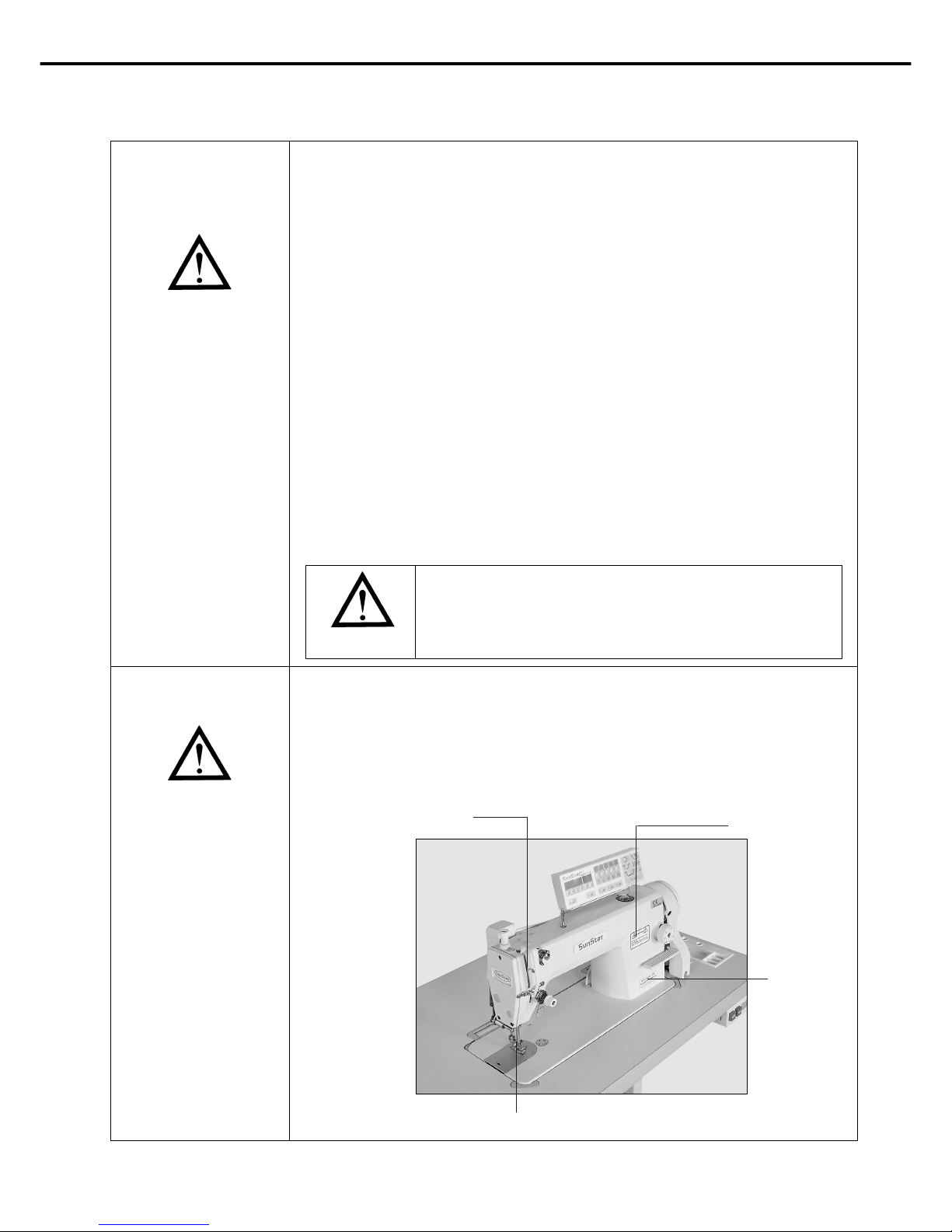
ⓐ
Safety Label: Suggestions while running the machine are stated.
ⓑ
Thread take-up spring cover: the device to prevent the human body from touching the thread
take-up spring.
ⓒ
Belt cover: the device to prevent hands, feet and clothing from getting jammed by the belt.
ⓓ
Finger guard: the device to prevent fingers from contacting the needle.
1-5) Safety Device
Warning
Always start the machine with safety covers in place since
fingers or hands could be injured or cut off by the belt. Turn off
the power switch during check-ups or adjustments.
ⓓ
ⓐ
ⓒ
ⓑ
7
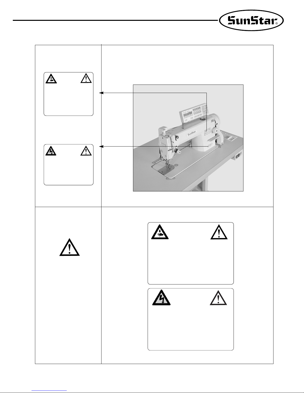
“Caution mark” is attached to the machine for safety. In case of starting to run the
machine, read the directions of “Caution mark” carefully.
1-6) Position of
Caution Mark
1-7) Content of
“Caution”
Caution
CAUTION
경고
Do not operate without finger guard and
safety devices. Before threading, changing
bobbin and needle, cleaning etc. switch off
main switch.
손가락 보호대와 안전장치 없이 작동하지
마십시오.
실, 보빈, 바늘교환시나 청소전에는 반드시
주전원의 스위치를 꺼 주십시오.
CAUTION
경고
Hazardous voltage will cause injury.
Be sure to wait at least 360 seconds before
opening this cover after turn off main switch
and unplug a power cord.
고압 전류에 의해 감전될 수 있으므로 커버를
열 때는 전원을 내리고 전원 플러그를 뽑고
나서 360초간 기다린 후 여십시오.
CAUTION
경고
Do not operate without finger guard
and safety devices. Before threading,
changing bobbin and needle, cleaning
etc. switch off main switch.
손가락 보호대와 안전장치 없이 작동하지
마십시오.
실, 보빈, 바늘교환시나 청소전에는 반드시
주전원의 스위치를 꺼 주십시오.
CAUTION
경고
Hazardous voltage will cause injury.
Be sure to wait at least 360 seconds
before opening this cover after turn
off main switch and unplug a power
cord.
고압 전류에 의해 감전될 수 있으므로 커버를
열 때는 전원을 내리고 전원 플러그를 뽑고
나서 360초간 기다린 후 여십시오.
[Position of Caution Mark]

1) Automatic thread trimming sewing machine
KM-250BL
8
1
Specification
Item
KM-250BL
KM-250BL-7S
KM-250BL-7N
Usage
Heavy Material
Heavy Material
Heavy Material
Max speed
Max 3500spm
(Average 3000spm)
Max 3500spm
(Average 3000spm)
Max 3500spm
(Average 3000spm)
Max stitch Length
0~7mm
0~7mm
0~7mm
Needle
DB 1×#20~#23
DB 1×#20~#23
DB 1×#20~#23
Presser Foot Height
Manual 5.5mm
Knee 14mm
Manual 5.5mm
Knee 14mm
Manual 5.5mm
Knee 14mm
2) Servo motor
MODEL
SC55-1A
SC55-2A
SC55-3A
VOLT
ONE PFAHSE 110V
ONE PFAHSE 220V
THREE PHASE 220V
WATT
550W
550W
550W
HERTZ
50/60 Hz
50/60 Hz
50/60 Hz
3) 470 motor
MODEL
PM470
PHASE
1 : 1
1 : 1
3 : 3
3 : 3
1 : 1
3 : 3
HERZ
5 : 50Hz
6 : 60Hz
5 : 50Hz
6 : 60Hz
5 : 50Hz
6 : 60Hz
5 : 50Hz
6 : 60Hz
5 : 50Hz
6 : 60Hz
VOLT
1 : 110V
2 : 220V
3 : 380V
4 : 110V / 220V
5 : 220V / 380V
9
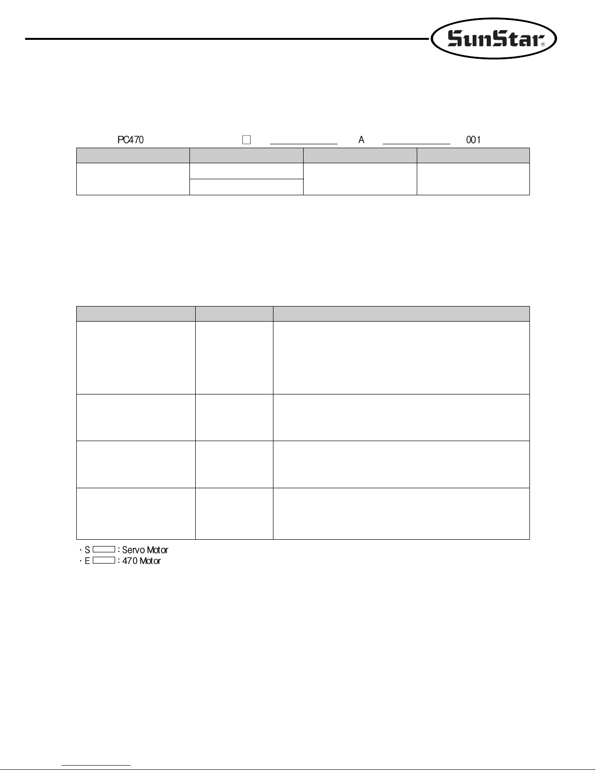
4) 470 motor control
MODEL
PC470
VOLT
1 : 110V
2 : 220V
MODEL
A
SUB CLASS
001
UsageModelOptional device
5) Peripheral automation device (optional)
AUTO KNEE LIFTING
SYSTEM
PRODUCTION COUNTER
MATERIAL EDGE SENSOR
STANDING PEDAL
SCOUN-1
SEDG-1
SEDG-2
SPDL-1
SPDL-2
A counting device which indicates the completed quantity on the
program unit panel, including added, subtracted, corrected or
remaining quantity along with other performance rates.
A device that senses the edge or thickness of the sewing material
to stop the machine without manual pedaling. Available in two
types: SEDG-1 for edge sensing type and SEDG-2 for thickness
sensing type.
An essential device when one person is operating multiple sewing
machines. Has different pedals for acceleration, thread trimming,
presser foot and ascending pedal. Types consist of SPDL-1 EDPL1 for fixed speed and SPDL-2 EDPL-2 for variable speed.
SPF-5
A solenoid operating structure where the presser foot gets lifted
automatically with pedal reverse gear stage 1 operation.
·
max. stroke: 10.3mm
·
input voltage: DC 24V (DC 24 ~ 46V)
·
induction at 10.3mm stroke: 26kg
 Loading...