

Page 1
(Over please)
24148-03A
IMPORTANT
SunStar ZX30/32 Stereo Installation Instructions
(Disregard the INSTALLATION MANUAL supplied with the stereo.)
Follow these instructions carefully. Check the serial number
label on your sunbed. The model name designates a design series,
by a letter, followed by the bed model (i.e. K-ZX32-3FH). If the first
letter is an H or J you will need to use the hole drilling template
included with this instruction sheet. If it is K or above your sunbed
already includes the needed holes and you can disregard the hole
drilling template and all instructions referring to it. The bench and
canopy have been deleted for illustration purposes only. You do
not need to disassemble your sunbed to perform this installation.
SPACER
SPEAKER
NUT
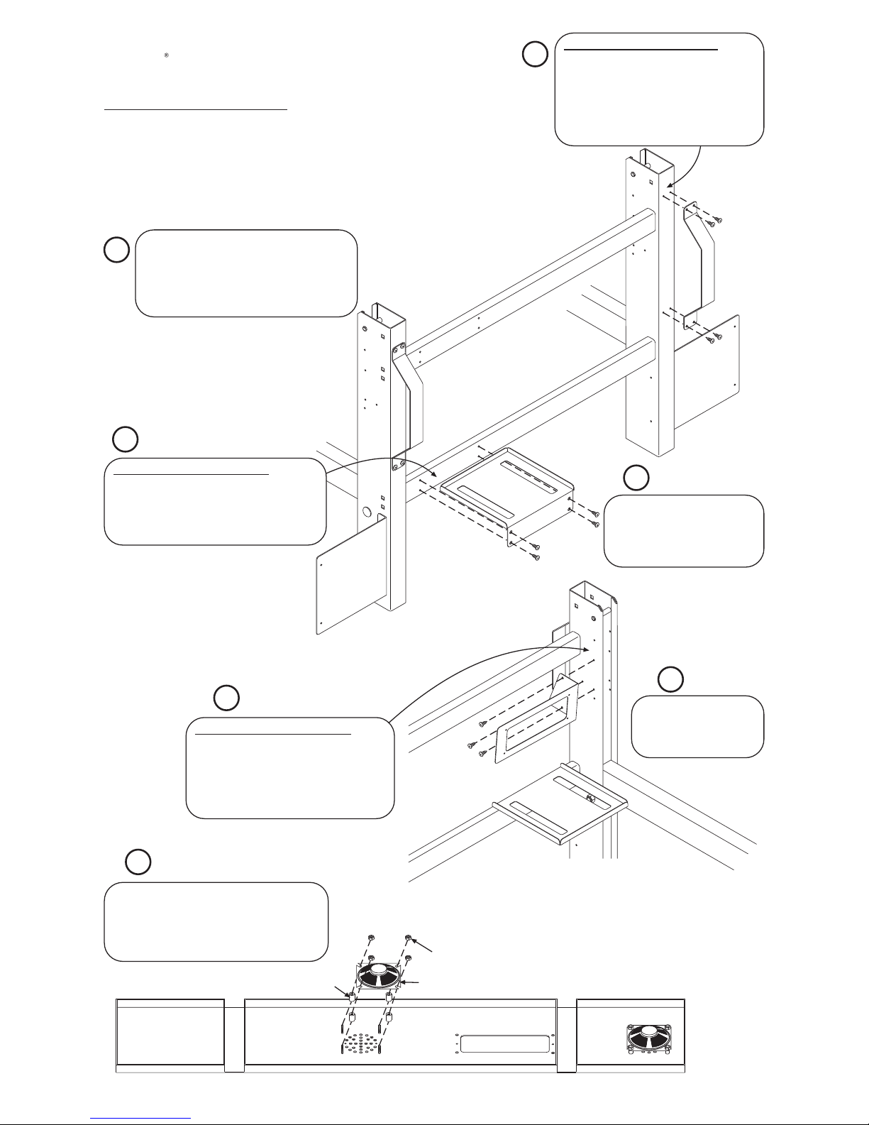
HOLE DRILLING TEMPLATE 2
Find the template labelled “Power Supply
Bracket”. Carefully cut it out on the dashed
line and apply it to the back of the cross bar
with tape. Drill the four holes with a 5/32”
drill bit where shown. Remove the template.
Pull the sunbed away from the back wall,
enough to work behind it. Remove the Gas
Spring Cover Panel and set aside. If your
Gas Spring Cover Panel does not contain
stereo and speaker holes you will need to
replace it with a new panel.
Install the Stereo Support
Bracket as shown with
(3) unpainted #10 x 1/2”
screws.
Place the Gas Spring Cover Panel face down.
Put four plastic spacers on the screw studs
around the speaker holes. Place the speaker
onto the studs and secure with four nuts, as
shown below.
Find the three brackets shown
in the kit (two Stand Spacer
Brackets and one Power Supply
Bracket). Install them with
unpainted #10 x 1/2” screws.
4
2
3
1
5
6
7
HOLE DRILLING TEMPLATE 3
Find the template labelled “Stereo Support
Bracket”. Carefully cut it out on the dashed
line and apply it to the inside of the right
stand leg with tape. Drill the three holes
with a 5/32” drill bit where shown. Remove
the template.
HOLE DRILLING TEMPLATE 1
Find the template labelled “Stand Spacer
Bracket”. Carefully cut it out on the dashed
line and apply it to the back of the stand
leg with tape. Drill the four holes with a
5/32” drill bit where shown. Use the same
template for the other stand leg. Remove
the template.
Page 2
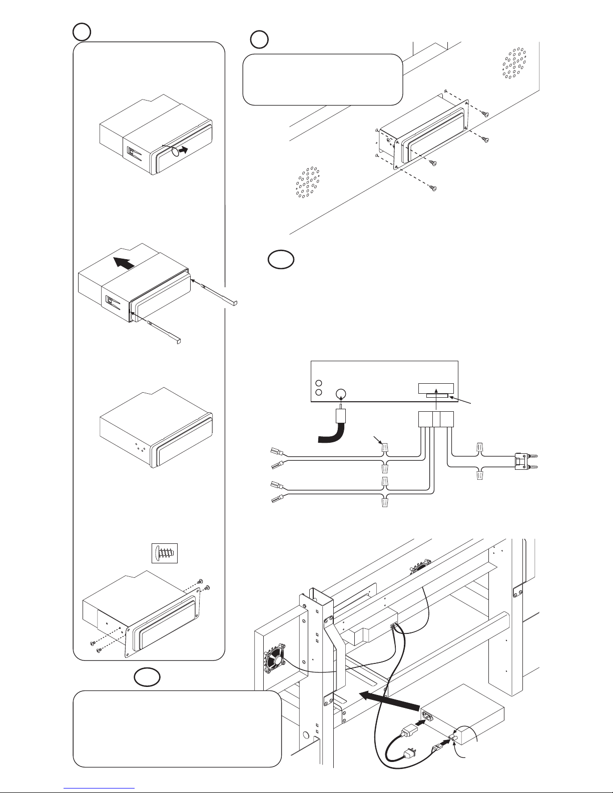
C. REPLACE THE FACEPLATE
Snap the faceplate back onto the front
of the stereo.
CONNECT THE WIRING
Included in the Stereo Installation Kit are three wire harnesses, two for the
speakers and one for the Stereo Power Supply. You will also use the wiring
harness supplied with the stereo. Plug the stereo wiring harness into the back
of the stereo. Connect the other three wire harnesses to it as described in the
illustration below. Connect the wires with wire nuts. There will be (6) wires on the
stereo wiring harness not used which should be cut off close to the connector.
Plug in the antenna, included with the Stereo Installation Kit.
D. A TTACH THE MOUNTING BRACKET
Slide the stereo into the mounting bracket
as shown. Secure it in place with four
screws supplied with the stereo. Use the
ones with rounded heads as shown in the
illustration below.
B. REMOVE THE MOUNTING SLEEVE
Slide the two pullers straight into the slots
on both sides of the stereo until they click.
Pull the mounting sleeve off of the stereo
and discard.
A. REMOVE THE FACEPLATE
Using the small wire tool, carefully pull
the face plate off. Simply hook one of the
notches and pull up and out, as shown.
Do the same at all four notches to release
the faceplate.
Grey
Grey/Black
White
White/Black
Black
Red
Antenna
Fuse
To Left
Speaker
To Right
Speaker
Striped or Ribbed Wire
Striped or Ribbed Wire
Wiring Harness
with Stereo
To Power
Supply
Back of Stereo
Black
Red
Wire
Nut
Reinstall the Gas Spring Cover Panel with the
same screws taken out earlier. Slide the stereo
assembly into the slot in the Gas Spring Cover
Panel and secure in place with four #10x1/2”
screws with blue heads.
RED WIRE
POWER SUPPLY
8
9
10
11
BLACK WIRE
Place the Power Supply on the Power Supply Bracket. Plug
its power cord into it and into a 110V wall receptacle. Plug
the two-prong wire harness, from the stereo, into the Power
Supply. A label has been supplied with this kit to remind you
how to connect the two-prong plug. Apply it on top of the
Power Supply, directly over the connection. Connect the
speaker wires to the speakers. Turn the Power Supply on.
Page 3

STAND SPACER
BRACKET
Cut this template out
along the dashed line.
T ape it to the back of the
stand leg with the top of
the template even with
the top of the stand leg.
Drill (4) holes where
shown with a 5/32” drill.
TOP
STEREO SUPPORT
BRACKET
Cut this template out
along the dashed line.
T ape it to the inside of the
right stand leg with the
top of the template even
with the top of the stand
leg. Drill (3) holes where
shown with a 5/32” drill.
TOP
CROSS MEMBER
POWER SUPPLY BRACKET
Cut this template out along the dashed line. T ape
it to the back of the lower cross member support
with the right of the template touching the stand
leg. Be careful to center the template on the
cross member from top to bottom. Drill (4) holes
where shown with a 5/32” drill.
STAND LEG
TOP
24148-03A
Sheet 2
HOLE DRILLING TEMPLATES
For Optional Stereo Installation Kit
 Loading...