

SunStar SWF Series, SWF E Series User Manual

MMMMEE--009900992299
USER
’’
S MANUAL
FOUR-HEAD AUTOMATIC
EMBROIDERY MACHINE WITH
FLAT
SIX-HEAD AUTOMATIC
EMBROIDERY MACHINE WITH
FLAT
SSuunnSSttaarr CCOO..,, LLTTDD..
SWF/E- Series

1. THIS IS AN INSTRUCTION FOR SAFE USE OF AUTOMATIC
EMBROIDERY MACHINES. READ THOROUGHLY BEFORE USE.
2. CONTENTS IN THIS INSTRUCTION MAY CHANGE, WITHOUT
PRIOR NOTICE, FOR IMPROVEMENT OF MACHINE QUALITY AND
THUS MAY NOT CORRESPOND TO THE MACHINE YOU
PURCHASED. CONTACT YOUR SALES AGENT FOR INQUIRIES.
3. THIS IS DESIGNED AND MANUFACTURED AS AN INDUSTRIAL
MACHINE. IT SHOULD NOT BE USED FOR OTHER THAN
INDUSTRIAL PURPOSE.

i
CHAPTER 1 SAFETY RULES …………………………………………………………………… 1-1
1-1) MACHINE DELIVERY ……………………………………………………………… 1-1
1-2) MACHINE INSTALLATION ………………………………………………………… 1-2
1-3) MACHINE OPERATION …………………………………………………………… 1-3
1-4) REPAIR ……………………………………………………………………………… 1-3
1-5) PLACEMENT OF WARNING STICKERS ………………………………………… 1-4
1-6) CONTENTS OF WARNING STICKERS …………………………………………… 1-5
CHAPTER 2 INSTALLATION AND MACHINE ASSEMBLY ………………………………… 2-1
2-1) ENVIRONMENT …………………………………………………………………… 2-1
2-2) ELECTRICITY ……………………………………………………………………… 2-1
2-3) LEVELING THE MACHINE ………………………………………………………… 2-2
2-4) ASSEMBLY OF PERIPHERAL DEVICES ………………………………………… 2-3
CHAPTER 3 PARTS OF THE MACHINE ………………………………………………………… 3-1
CHAPTER 4
FUNCTIONS AND FEATURES …………………………………………………… 4-1
CHAPTER 5
FUNCTIONS FOR BASIC MACHINE OPERATION ……………………………… 5-1
5-1) EMERGENCY POWER AND START/STOP/BAR SWITCH ……………………… 5-1
5-2) EMERGENCY STOP ………………………………………………………………… 5-3
5-3) LAMP ON THREAD TENSION ADJUSTMENT BOARD ………………………… 5-4
5-4) NEEDLE STOP CLUTCH …………………………………………………………… 5-5
5-5) UPPER THREADING AND TENSION ADJUSTMENT …………………………… 5-6
5-6) LOWER (BOBBIN) THREADING AND TENSION ADJUSTMENT ……………… 5-9
5-7) THREAD WINDER ………………………………………………………………… 5-10
5-8) PRECAUTIONS IN USING FLOPPY DISKS OR USB MEMORY STICKS ……… 5-12
5-9) INSERTING FLOPPY DISKS AND USB MEMORY STICKS …………………… 5-13
5-10) DELETING FLOPPY DISKS AND USB MEMORY STICK ……………………… 5-13
5-11) READING AND WRITING OF EMBROIDERY DESIGNS ……………………… 5-13
5-12) RETURN TO PREVIOUS LOCATION IN UNEXPECTED BLACKOUTS ……… 5-13
5-13) NEEDLE-HOOK TIMING CONTROL …………………………………………… 5-14
5-14) ASSEMBLY AND FUNCTIONS OF THREAD DETECTOR …………………… 5-19
CHAPTER 6 MAINTENANCE AND INSPECTION …………………………………………… 6-1
6-1) CHECK POINTS FOR REGULAR INSPECTION ………………………………… 6-1
6-2) CLEANING …………………………………………………………………………… 6-1
6-3) OIL SUPPLY ………………………………………………………………………… 6-3
6-4) DRIVE BELT TENSION …………………………………………………………… 6-7
TABLE OF CONTENTS

ii
CHAPTER 7 MACHINE ADJUSTMENTS ……………………………………………………… 7-1
7-1) ADJUSTING THE TRIMMERS ……………………………………………………… 7-1
7-2) ADJUSTING THE TRIMMER RETURN SPRING ………………………………… 7-3
7-3) PICKER ADJUSTMENT …………………………………………………………… 7-4
7-4) ADJUSTING UPPER THREAD HOLDER ………………………………………… 7-4
7-5) ADJUSTING HEIGHT OF PRESSER FOOT ……………………………………… 7-6
7-6) CORRECT POSITION OF NEEDLE ………………………………………………… 7-7
7-7) ADJUSTING HALF-TURN FILM FOR COLOR CHANGE ……………………… 7-8
7-8) ENCODER ADJUSTMENT ………………………………………………………… 7-8
7-9) JUMP SOLENOID ADJUSTMENT ………………………………………………… 7-9
CHAPTER 8 TROUBLESHOOTING ……………………………………………………………… 8-1
1-1
The following set of safety rules categorized as DANGER, WARNING, and CAUTION indicates possibilities of
physical or property damages if not fully observed.
: These safety instructions MUST be observed to be safe from danger when installing, delivering, or
repairing the machine.
: These safety instructions MUST be observed to be safe from machine injuries.
: These safety instructions MUST be observed to prevent predictable machine errors.
CAUTION
WARNING
DANGER
SAFETY RULES
CHAPTER 1
ONLY TRAINED AND EXPERIENCED PERSONS, FAMILIAR WITH THE
RELEVANT SAFETY INSTRUCTIONS, SHOULD HANDLE THE
MACHINE. MAKE SURE TO FULLY OBSERVE THE FOLLOWING
INSTRUCTIONS.
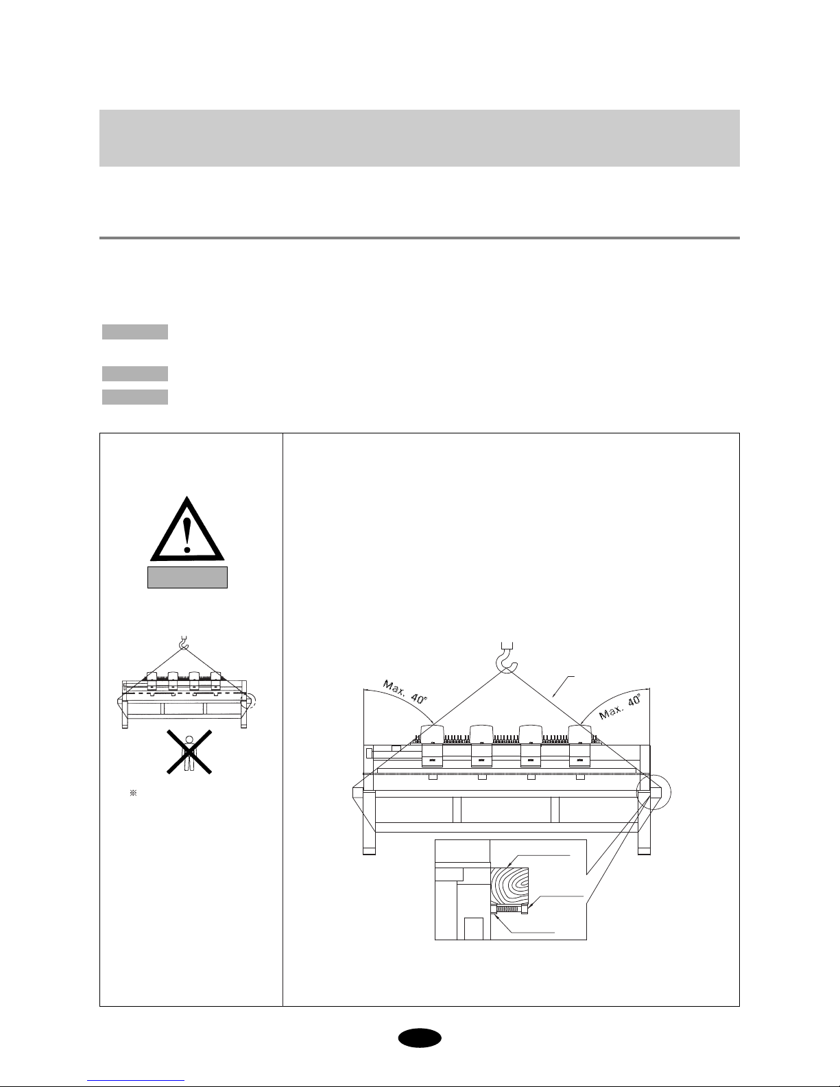
1) Using a crane
Make sure that the crane is large enough to hold the machine. Use a nylon
rope of sufficient strength. Place a wooden block at either side of the
machine before tying the rope. The angle should be 40°or less. Make sure
that the rope does not touch the table.
Make sure all persons
and obstacles are out
of the way of the
moving equipment.
[Fig.1-1]
1-1) MACHINE
DELIVERY
DANGER
Wooden block
Nylon rope
Bolt
Nut
1-2
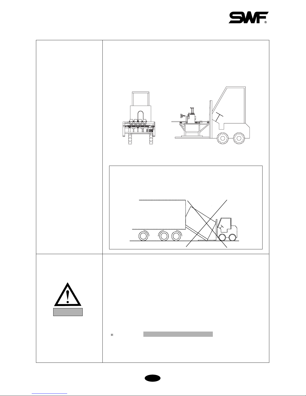
2) Using a Forklift
Make sure that size and weight of the forklift is sufficient to support the
machine. Use the pallet to place the machine so that its center is on the
forklift arm (see [Fig.1-2]). Lift the machine carefully so that the machine
does not tilt to either side.
[Fig.1-2]
Installation environment may incur machine malfunction or breakdown.
Make sure to meet the following conditions.
1) The foundation under the machine, i.e. table or desk, must be strong enough
to support the weight of the machine (approximately 1 ton).
2) Air conditioning can eliminate dust and humidity that can cause pollution
and corrosion of the machine. Make sure your machine is regularly cleaned.
3) Long exposure to direct sunlight can cause the paint of the machine to fade
or change of the machine shape.
4) Allow at least 50cm (20 inches) of space on each side of the machine for
convenient maintenance.
Please refer to for installation details.
2. Machine Installation and Assembly
1-2) MACHINE
INSTALLATION
CAUTION
[WARNING]
Make sure to maintain the weight balance in machine deliveries,
especially when unloading the machine from a forklift or crane, in
order to prevent injury or machine damages.
1-3
Only SWF-trained and selected repair engineers should do repair work.
1) Turn OFF the power before cleaning or repairing the machine. Wait for 4
minutes so the machine electricity is completely discharged.
2) Do not change the settings or any parts on the machine without
confirmation from SWF. Such change may cause safety accidents.
3) Use only SWF parts when repairing your machine.
4) Replace all safety covers when you are finished with your repair.
1-4) REPAIR
DANGER
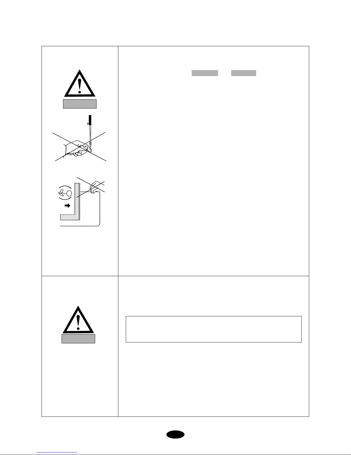
The SWF Automatic Embroidery Machine is designed for applying
embroidery to fabric and other similar materials.
Pay careful attention to the and stickers on certain
parts of the machine. Make sure to observe the following when operating
the machine:
01) Read thoroughly and fully understand the manual before operating the
machine.
02) Dress for safety. Long and unbound hair, jewelry such as necklaces,
bracelets, and wide sleeves can get caught in the machine. Wear shoes with
non-slip soles.
0
3) Clear all persons from the machine before turning on the power.
04) Keep your hands or head away from the moving parts of the machine such
as needle, hook, take-up lever, and pulley when the machine is in
operation.
05) Do not remove the safety cover on the pulley or shaft when the machine is
in operation.
06) Be sure the main power is turned off and the power switch is set to OFF
before opening the cover of any electrical component or control box.
0
7) Be sure the main switch is OFF before manually turning the main shaft.
08) Turn the machine off when threading needles or inspecting the finished
embroidery.
0
9) Do not lean against the cradle or place your fingers near the guide grooves
of the frame.
10) The machine noise may exceed 85db when it is run at a maximum speed. It
is not higher than the standard level, but you may need earplugs or soundproof facilities for the operator and other workers.
CAUTIONWARNING
1-3) MACHINE
OPERATION
[CAUTION]
It takes about 10 minutes after turning off the main switch before the
electricity is fully discharged from X/Y main shafts and the drive box.
WARNING
1-4
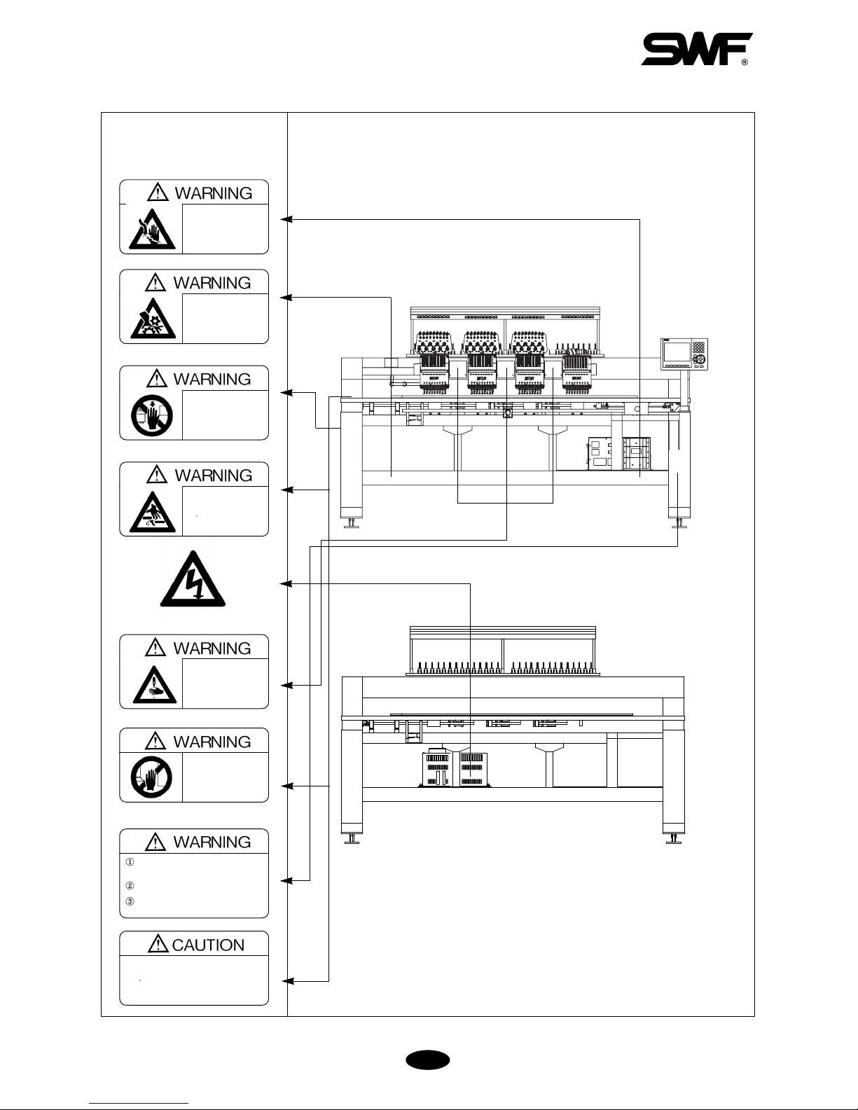
1-5)
PLACEMENT OF
WARNING STICKERS
Fire or death may be caused by
high voltage electric shock.
Don’t open the cover except for
service man assigned by SWF.
When open the cover turn off
power and wait for 6 minutes.
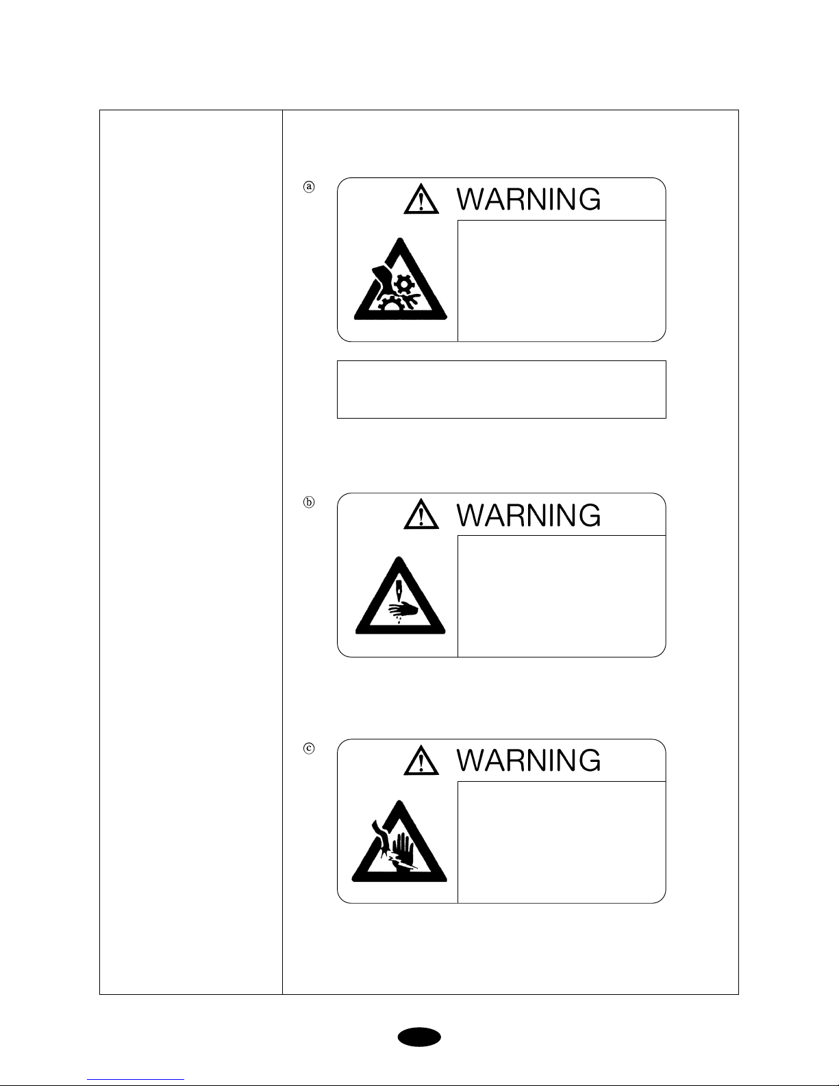
[Fig.1-4] From top
Physical damage may be caused by winding
Don t put your hands near the needle bar &
take-up lever while machine is runing.
Injury may be caused by winding.
Be sure to turn off the power
before cleaning, lubricating,
adjusting or repairing.
Physical damage may be
caused by winding.
Don’t put your hands near the
arrow while the main shaft is
rotating
Injury may be caused by moving
needle.
Ensure that the machine is in a
stop condition before changing,
threading or rethreading of
needies or changing of needles.
Turn off the main power before rotating the
main shaft by hand!
Do not remove covers during operation!
Turn off the main power before opening
electricity-related boxes!
Physical damage may be caused
by interposition.
While embroidery frame is running
according to the direction of
embroidery frame may be injured
your hands by gap between fixed
body and embroidery frame.
Physical injury may be caused
by crevice.
Don t put your finger in a groove
on the table.
[Fig.1-3] Front
Observe the directions on ALL warning stickers placed on the machine as
reminders for your safety.
1) Location of Warning Stickers
1-5
1) Warning
1-6) CONTENTS OF
WARNING
STICKERS
Injury may be caused by moving needle.
Ensure that the machine is in a stop
condition before changing, threading or
rethreading of needies or changing of
needles.
Fire or death may be caused by high
voltage electric shock.
Don’t open the cover except for service
man assigned by SWF.
When open the cover turn off power and
wait for 6 minutes.
[ Notice ]
Cover in the “WARNING” means all covers near
operating part of the machine.
Injury may be caused by winding.
Be sure to turn off the power before
cleaning, lubricating, adjusting or
repairing.

2-1
Install your machine in an appropriate environment and with adequate electrical supply. Failure to follow the
directions may result in machine malfunction.
2-1) ENVIRONMENT
1) Temperature: ① 0 ∼ 40℃ (32 ∼ 104°F) when the machine is in operation
②-25 ∼ 55℃ (-13 ∼ 131°F) when the machine is not in operation
2) Humidity: 45 ∼ 90% (relative)
3) Grounding: Ensure the electricity is properly grounded.
4) Close any doors and windows near the machine to prevent direct light, dust, and humidity.
5) Foundation under the machine must be a sufficiently strong and flat concrete to support the weight of the
machine.
2-2) ELECTRICITY
Check if the input voltage of the machine is in the right range of the voltage supply before installing or operating
the machine. The voltage required is as follows:
1) Input voltage (to be adjusted when installing): 100V, 110V, 120V, 200V, 220V, 240V
2) Allowed range of voltage: within ±10% of the voltage set
3) Electric capacity and voltage consumption: 640VA 440W
4) Insulation resistance: over 10M ohms (measured with 500V insulation tester)
INSTALLATION AND MACHINE ASSEMBLY
CHAPTER 2
WARNING
DANGER
Properly ground the machine to avoid the possibility of electric shock. Use three-wire grounding
(grounding resistance below 100 ohms).
Check the voltage supply where the machine will be installed.
Install the cable away from the operator s work space to prevent accident or injury.
[CAUTION]
Do NOT let moisture drops on the machine.
Provide air conditioning to control humidity and to prevent dust and corrosion.
2-2
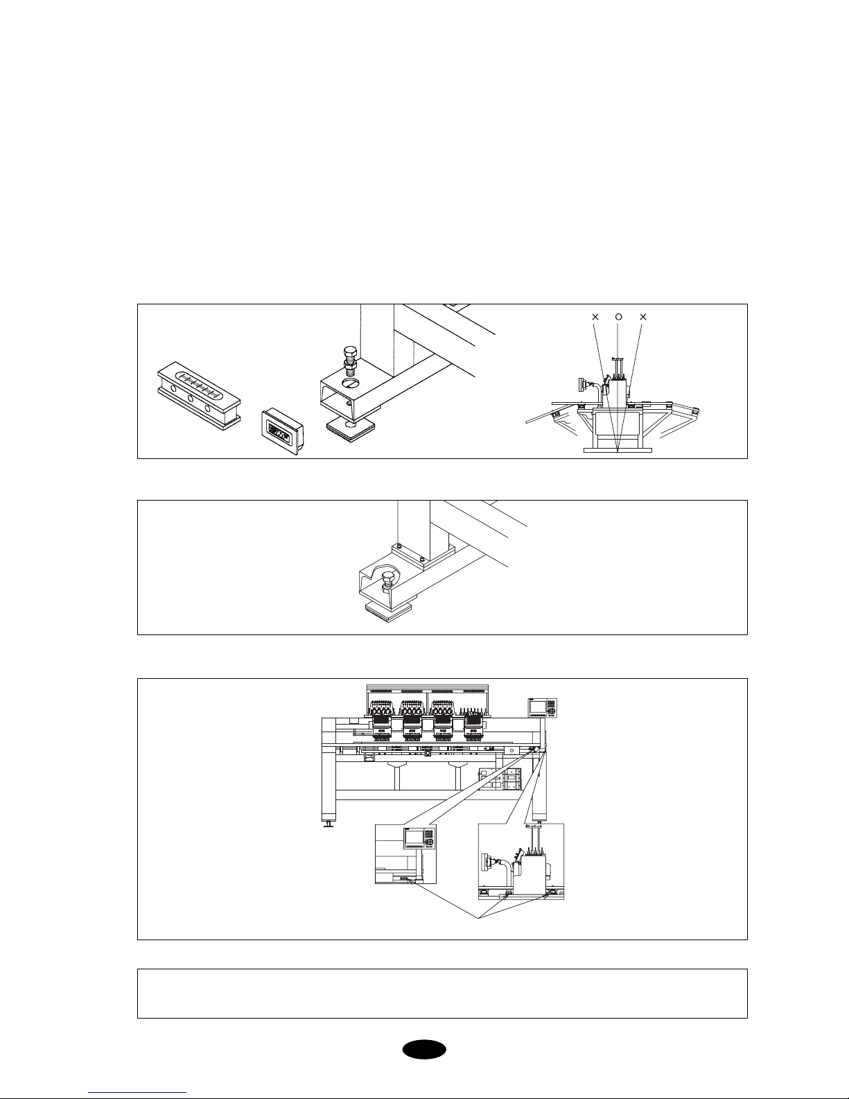
2-3) LEVELING THE MACHINE
The machine must be accurately leveled (especially front and back) to prevent the needle from moving out of
position.
1) Use the adjusting bolts installed at the four stands to level the machine (front, rear, left, and right). Use a level
gauge.
① Check the voltage supply where the machine will be installed.
② Install the cable away from the operator’s work space to prevent accident or injury.
③ If the difference in heights of the four bolts is over 10mm, place spacers beneath the lower adjusting bolts to
make the heights even.
2) Use a nut to fasten the bolts when the machine is horizontally leveled.
[CAUTION]
The level gauge does not measure accurately on a square pipe or a table.
[Fig.2-2]
3) Using the level gauge
[Fig.2-3]
[Fig.2-1]
Level gauge
Level gauge
Adjusting bolts
Level base
2-3
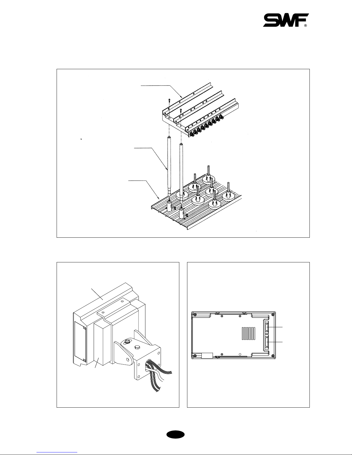
2-4) ASSEMBLY OF PERIPHERAL DEVICES
1) Assembling Upper Thread Stand
[Fig.2-4]
[Fig.2-5]
[Fig.2-6]
2) Assembling Operation Box
Spool plate
Thread holder
Operation box
FDD
Support
Power
Cable
FDD Cable
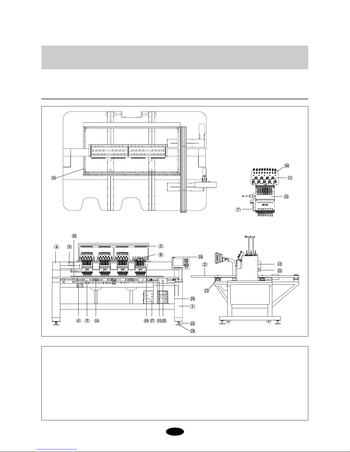
3-1
[Fig.3-1]
① Machine Body
② Table
③ Upper thread stand
④ Main shaft drive motor
⑤ Rotary hook base
⑥ Trimming cam box
⑦ Arm
⑧ Color Change
⑨ Upper thread holder
⑩ Head
⑪ Thread tension adjustment board
⑫ Sub-controller
⑬ X-axis driving system
⑭ Y-axis driving system
⑮ Bar switch
⒃ Frame
⒔ Main controller box
⒕ Operation box
⒖ Encoder
⒗ Main power switch
Lamp
Supporting bolt
Leveling base
Thread detector
Emergency power switch
PARTS OF THE MACHINE
CHAPTER 3

4-1
1) EXPANDED MEMORY SIZE
The machine can store a maximum of 100 designs. The basic memory size is 2 million stitches.
2) MIRROR IMAGE CONVERSION AND DESIGN DIRECTION
You can turn the design from 0°to 359°in the increments of 1°and also reverse the design in the X direction
(mirror image).
3) ENLARGING AND REDUCING DESIGN
You can reduce or enlarge the embroidery design in size from 50% to 200% by 1% along the X and Y axis.
4) AUTOMATIC SELECTION OF NEEDLE BAR
You can select the order of the needle bars up to the 99th bar.
5) GENERAL REPETITION WORK
The same design can be repeated up to 99 times along the X and Y axis.
6) AUTOMATIC OFFSET
The frame automatically returns to the offset point when the embroidery is finished to make it easier for you to
switch the frames. You can select AUTOMATIC OFFSET at PARAMETER SELECT MODE to move the frame
automatically to the desired point, making it easier to do appliques and to switch the frames.
7) MANUAL OFFSET
You can manually move the frame to the pre-selected point to do appliques or change the frames during embroidery
work. The frame can be moved back to its original place by simply pressing the right buttons.
8) RETURN TO START
The frame can be moved back to the start point of the design during the embroidery work.
9) NON-STITCHING
The frame and the needle bar can move back and forth by the units of 1, 100, 1000, and 10000 stitches and by color
without stitching.
10)FRAME REVERSAL
When the thread breaks or runs out of track, you can move the needle bar back to the starting point of the design in
the units of one to ten stitches.
11)AUTOMATIC TRIMMING
The automatic trimming function, determined by the design and the machine set-up, enhances work productivity and
quality of the finished product.
FEATURES AND SPECIFICATIONS
CHAPTER 4

4-2
12)AUTOMATIC DETECTION OF UPPER AND LOWER THREAD BREAKS
The machine detects when the upper thread breaks or the lower thread is out of the needle and automatically stops
the machine.
13)AUTOMATIC RETURN TO STOP POINT IN UNEXPECTED BLACKOUT
When the power fails unexpectedly, the frame moves back to the exact point where the stitching stopped. This helps
reduce the number of defects.
14)3.5'' FLOPPY DRIVE (EMBEDDED)
A 3.5'' floppy drive is embedded in the operation panel for you to read or store designs. Both 2DD and 2HD disks
can be used.
15)EDITING
You can delete, change, or insert stitch data and function codes (jump, finish, trimming).
16)INDIVIDUAL HEAD OPERATION
You can work on the specific head with a broken thread.
17)MACHINE STOPPAGE
The screen will indicate why the machine has stopped.
18)RPM
The screen indicates rpm.
19)FRAME SPEED SET-UP
You can adjust the frame speed to high, medium, or low.
20)UNUSED MEMORY
The screen indicates the memory available for use.
21)TAPE CODE COMPATIBILITY
2-binary and 3-binary tape codes can be edited.
22)CODES FROM OTHER BRANDS
The machine can automatically read designs of various formats stored in the floppy disk. These formats include
SST/ DST, DSB, DSZ/ TAP/ FMC, FDR/ ZSK/ 10O/ EXP.
23)USB memory drive
Designs can be input, output, and deleted using the USB stick.
5-1
FUNCTIONS FOR BASIC MACHINE OPERATION
CHAPTER 5
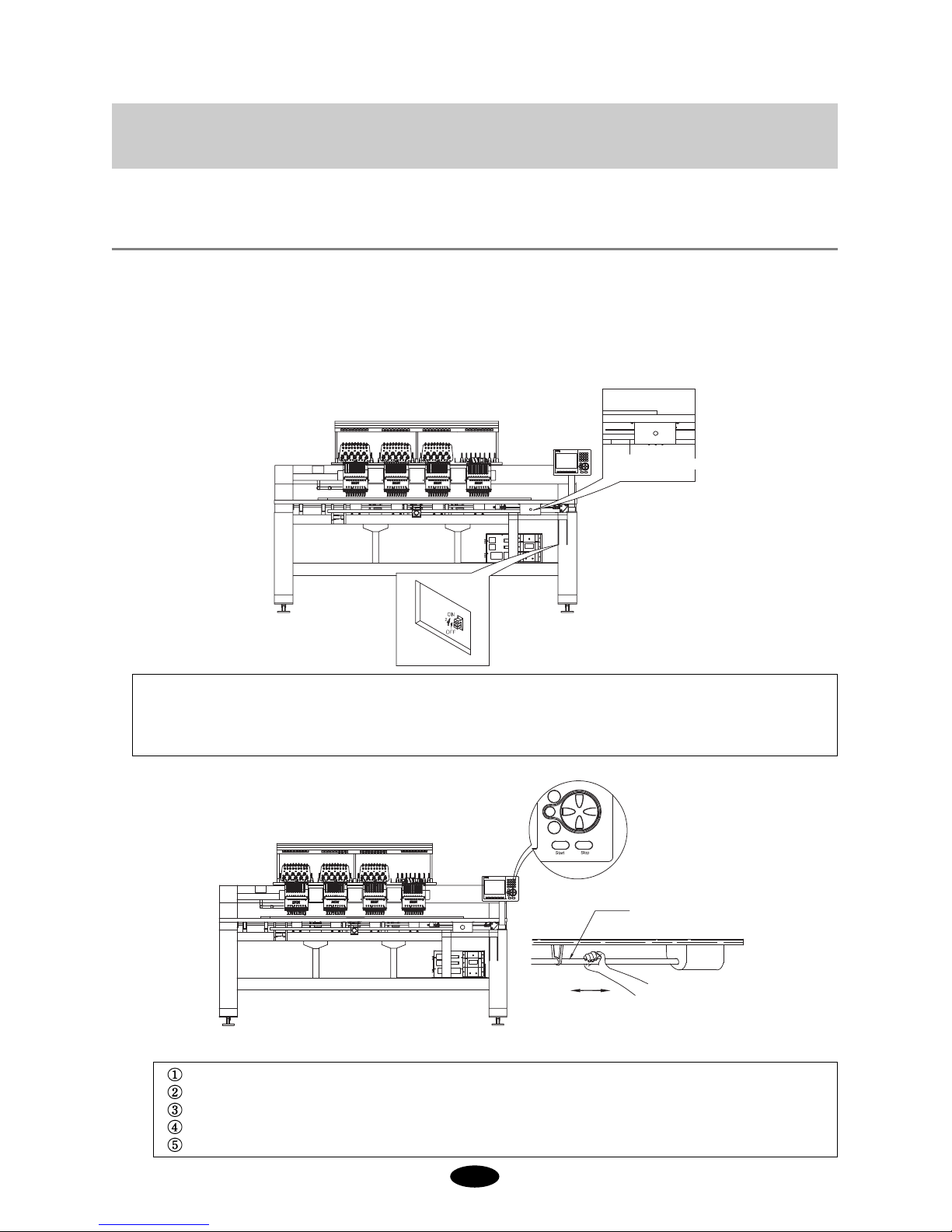
5-1) EMERGENCY POWER AND START/STOP/BAR SWITCH
5-1-1) Emergency Power Switch
Starting the machine in the initial stage
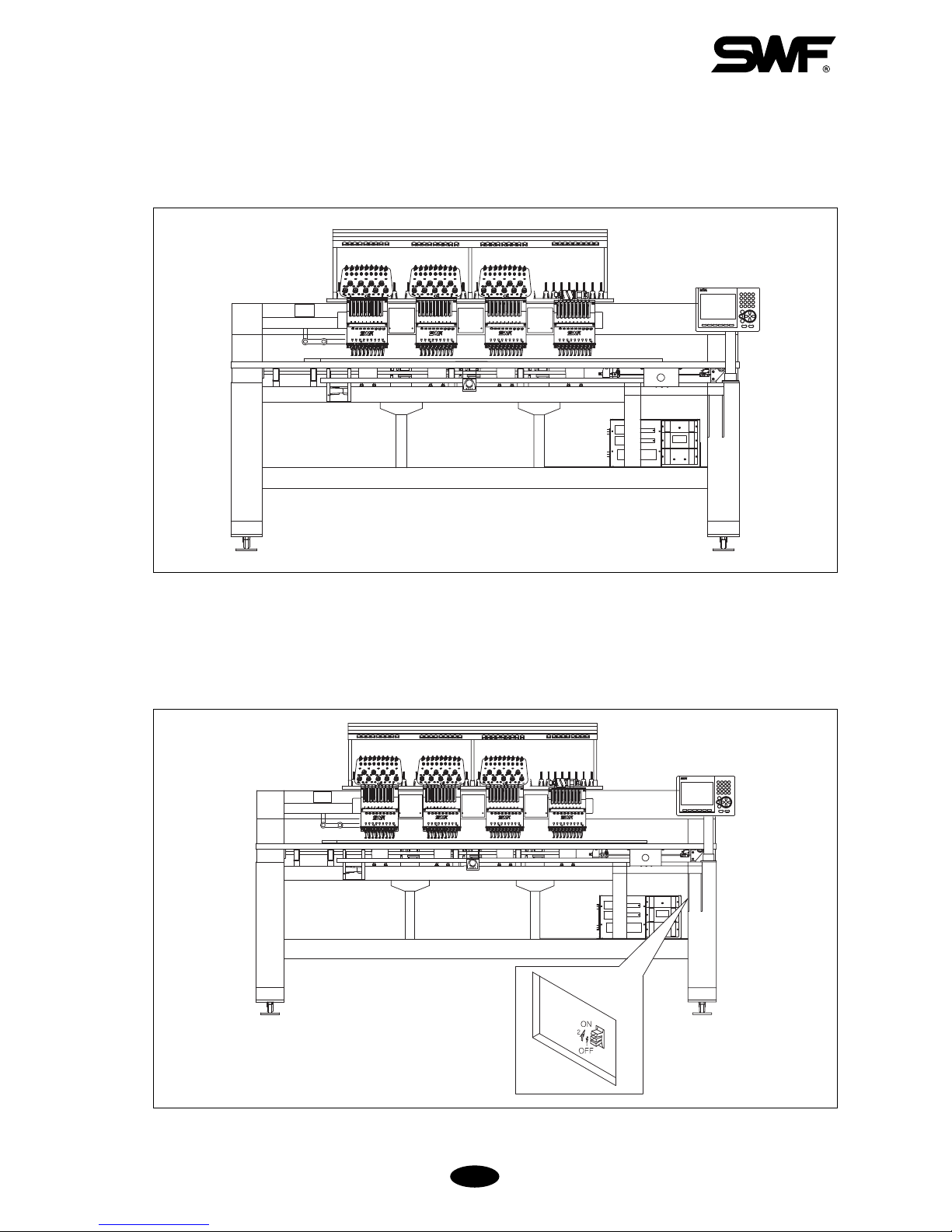
① Turn on the main power ([Fig.5-1]).
② Press the emergency power switch (green color).
③ Emergency power switch will not turn on if the main power is off.
5-1-2) Start/Stop Buttons & Bar Switch
[Fig.5-2]
Use the START/STOP buttons and Bar switch to:
Start the embroidery work or stop the machine during operation.
Move the frame back during machine stop.
Move forward in design during machine stop (non-stitching)
Move backward in design during machine stop (non-stitching)
Do work other than embroidery
Bar switch
(STOP)Left Right(START)
[Fig.5-1]
[NOTE]
Emergency power switch detects emergency stop failures and prevents accidents.
Emergency power function detects the failure of the emergency stop function and prevents the machine from
being switched on.
Emergency power switch

① START/STOP for starting embroidery and stopping the machine
5-2
Select function Press START
[NOTE 1]
Inching refers to low-speed embroidery at a 100 rpm range, performed for stable stitching when the
machine is re-started after stop.
[NOTE 2]
Frame movement unit refers to the BK STITCH UNIT in EMB FUNCTION. You can select from 1 to
10 stitches (by 1 stitch).
④ START /STOP during backward non-stitching (during machine stop)
See (2) START/STOP during machine stop.
⑤ Performing Work Other Than Embroidery
If you want to perform a solenoid test, a thread break sensor test, or manual trimming, select the function and
press START.
③ START/STOP during forward non-stitching (during machine stop)
BUTTON OPERATION
Press START
Hold START
Press START again
Frame moves forward in selected movement units (see Note 2)
Frame starts to move forward.
If you press START before the machine goes 10 of the selected stitches,
the machine will stop immediately (the machine moves back in the selected
movement units). If you press START after the machine traveled 10 of the
selected stitches, the machine will continue to move forward.
Press START one more time and the machine will stop moving forward.
MACHINE OPERATION
② START/STOP during machine stop
BUTTON OPERATION
Press STOP
Hold STOP
Press STOP again
Frame moves backward in selected movement units (see Note 2).
Frame starts to move backward.
If you press STOP before the machine goes 10 of the selected stitches,
the machine will stop immediately (the machine moves back in the
selected movement units). If you press STOP after the machine traveled
10 of the selected stitches, the machine will continue to move back.
Press STOP one more time and the machine will stop moving backward.
MACHINE OPERATION
[NOTE 1]
You cannot perform non-stitching (floating) at the start of the embroidery because the function is not in the
start menu. To perform floating at the start, press STOP to put the machine in STOP MODE. Then press
button to select the non-stitching function.
BUTTON OPERATION
Press START
Hold START
Press STOP
Machine starts and embroidery work begins.
Machine
inches (see Note1) until you release the button.
Machine stops.
MACHINE OPERATION
5-3
5-2) EMERGENCY STOP
Press EMERGENCY STOP if you have to stop the machine immediately, i.e. machine error.
① EMERGENCY STOP will turn off the machine.
② To restart the machine, rotate the main shaft to 100°.
③ Turn the EMERGENCY STOP button off and then on again.
[Fig.5-4]
[Fig.5-3]
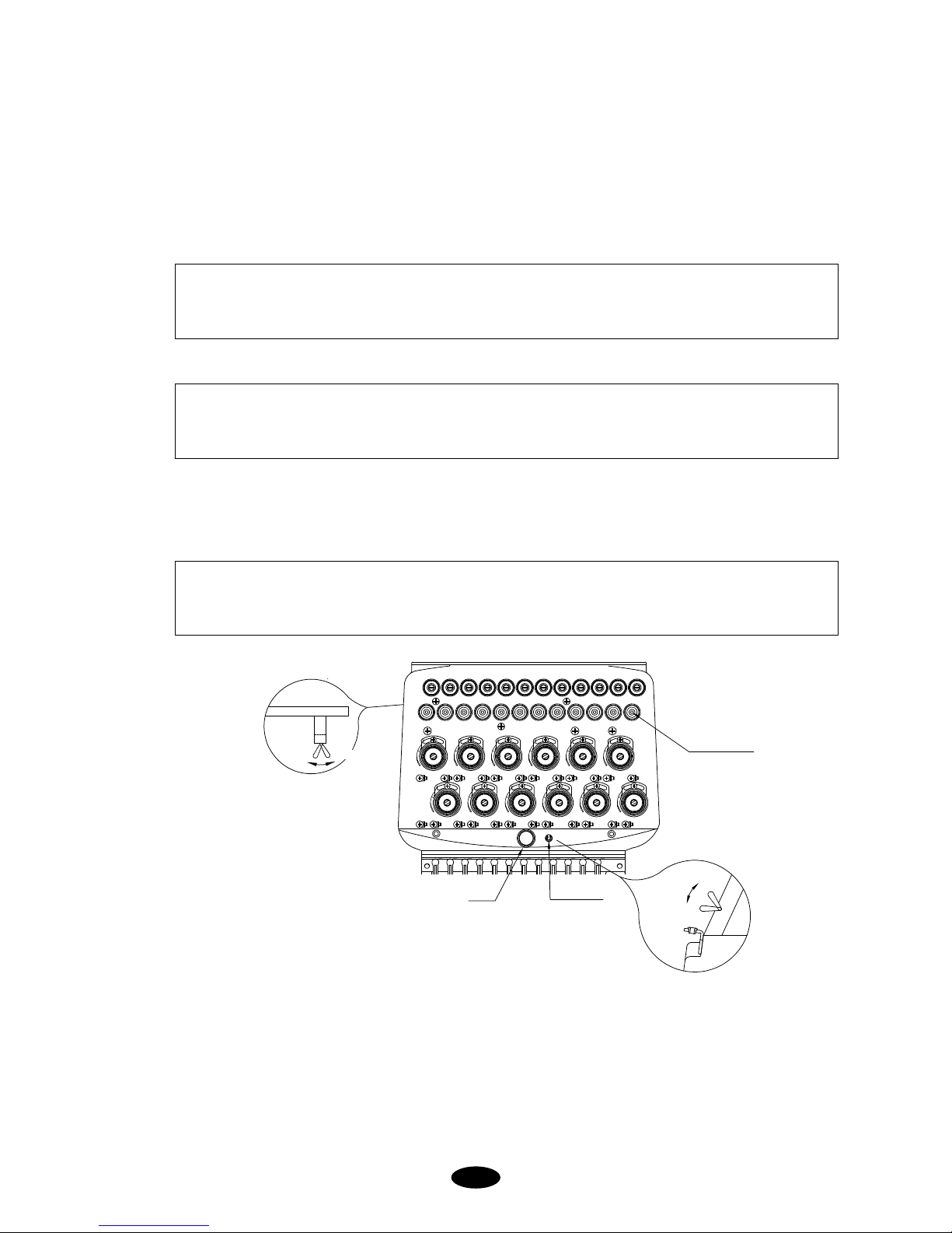
5-3) LAMP ON THREAD TENSION ADJUSTMENT BOARD
1) Switch
① For normal operation, turn the toggle switch on to turn on the indicator lamp.
② If the machine stopped after detecting a thread break, move the frame back to the location of the thread break
using STOP button and restart the machine to pick up stitching (design edit).
③ To set the needle bar so a specific head does not work, turn the toggle switch off.
2) Thread Break Detector Lamp
Lamp on a specific head will blink when thread break is detected at the head, while lamps on other heads will be
turned off. You cannot turn the lamp ON or OFF on the other heads using the toggle switch.
5-4
[Fig.5-5]
[CAUTION 2]
Foreign substances around the thread detector roller may block smooth rotation of the roller and cause
wrong detection of thread break.
[CAUTION 1]
The take-up lever continues to operate even when the head is turned off. This movement can cause the
upper thread to come out of the holder. Use a rubber magnet to fix the unused upper thread.
[NOTE]
If you want to move the frame back for any reason when a thread break has NOT occurred, press the
toggle twice (OFF and ON again).
3) Deletion of Thread-Break Detection Function
Poor function of the thread detecting roller due to foreign substances around it may result in wrong and frequent
detections, causing inefficiency of work. In this case, you can turn off the detecting function by turning off the
toggle switch at the end of the thread tension adjustment board. This will turn off the detecting function on the
head you are working with.
ON
Thread detection
delete
Lamp
Toggle switch
ON
Thread sensor roller
OFF
OFF
 Loading...